

A Coordinated Electric System Interconnection Review—the utility’s deep-dive on technical and cost impacts of your project.

GIC Mitigation and Transformer Thermal Assessment Services by Keentel Engineering

Calendar icon. D

May 15, 2025 | Blog

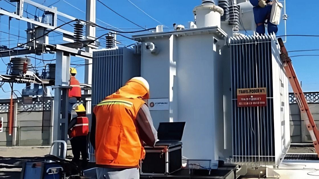
Workers in orange vests inspect a large electrical transformer outside on a sunny day.

Introduction: Understanding GIC Risk in Modern Power Systems

Geomagnetic disturbances (GMDs) caused by solar activity can induce quasi-dc currents in the power grid, known as geomagnetically-induced currents (GICs). These currents pose a significant risk to high-voltage transformers and the stability of the Bulk Electric System (BES). As a leader in GIC mitigation and thermal analysis, Keentel Engineering provides advanced GIC modeling services and transformer thermal impact assessments, ensuring full NERC TPL-007-1 compliance and long-term grid resilience.


What Are GICs and Why Do They Matter?

GICs occur when fluctuations in the Earth’s magnetic field—caused by solar storms—interact with the Earth’s conductive surface, creating electric fields. These electric fields drive quasi-dc currents into power systems, flowing through transformers and grounding paths.
Impacts of GICs include:

  • Hot spot heating and insulation degradation
  • Harmonics and voltage instability
  • Reactive power loss and system failures

NERC TPL-007-1 Compliance Requirements

The NERC TPL-007-1 standard requires utilities to:

  • Model benchmark GMD events (1-in-100-year)
  • Perform transformer thermal assessments
  • Implement mitigation strategies for at-risk assets

Keentel’s GIC Modeling Services

Keentel Engineering delivers GIC evaluations with precision using tools like PSCAD and EMTP-RV. Our modeling scope includes:

  • Geoelectric field calculations with Earth conductivity layers
  • DC network modeling of transformers and ground grids
  • Dynamic GIC(t) simulation with regional scaling

Transformer Thermal Assessment Capabilities

We assess thermal risk using:

  1. Manufacturer Curves: Comparing effective GIC to safe thermal thresholds.
  2. Thermal Response Models: Simulating hot-spot temperature rise using IEEE Std C57.91 parameters.

This data-driven method ensures safe loading limits are not exceeded during GMD events.


Engineering Judgment and Regional Risk Scaling

Keentel incorporates:

  • Latitude-dependent scaling (α)
  • Earth model variability (β)
  • Transformer type-specific behavior
  • Power System Study Solutions for scenario impact analysis

Why Choose Keentel Engineering?

Our end-to-end GIC mitigation solutions integrate:

  • Accurate transformer risk profiling
  • Thermal hotspot forecasting
  • NERC-compliant modeling and documentation

FAQs- GIC and Transformer Thermal Assessment

  • What is a GIC in power systems?

    A GIC is a quasi-dc current induced by geomagnetic disturbances that flows through transformers and ground paths in the power grid.

  • What causes GICs?

    GICs are caused by changes in the Earth’s magnetic field during solar storms, which induce electric fields that drive current in conductive structures like transmission lines.

  • How does GIC affect transformers?

    GIC can saturate transformer cores, generating harmonics, heating windings and metallic structures, and potentially damaging insulation.

  • What is the NERC TPL-007-1 standard?

    TPL-007-1 requires entities to evaluate their systems against benchmark GMD events and implement mitigation if necessary.

  • What are benchmark GMD event parameters?

    These include a peak geoelectric field magnitude of up to 20 V/km, adjusted based on geomagnetic latitude and earth conductivity.

  • What software tools are used for GIC modeling?

    Tools like PSCAD, PowerWorld, and EMTP-RV support GIC modeling. Keentel uses validated software compliant with NERC procedures.

  • What is the role of Earth conductivity in GIC modeling?

    Earth conductivity affects how electric fields propagate. A 1D or 3D conductivity model determines surface impedance and field strength.

  • How is the geoelectric field calculated?

    It’s derived from magnetic field measurements using FFT and Earth impedance models.

  • What is the skin depth in GIC studies?

    It refers to how deep magnetic fields penetrate the Earth; in GIC studies, it can range up to hundreds of kilometers.

  • What types of transformer configurations are susceptible to GIC?

    Grounded-wye windings are most susceptible. Delta windings block GIC flow due to lack of ground connection.

  • What is half-cycle saturation?

    It occurs when dc-like GIC biases the ac flux in the core, causing asymmetrical flux and increased losses.

  • What are hot spot temperatures?

    These are local high temperatures in transformer windings or structural parts due to GIC-induced losses.

  • What thresholds define GIC thermal risk?

    IEEE C57.91 suggests 180–200°C as emergency limits for metallic hot spots.

  • What is effective GIC (Idc,eq)?

    It’s a calculated value combining the GIC in different windings of an autotransformer, adjusted for turns ratio.

  • How is time series GIC(t) calculated?

    Using directionally scaled GICE and GICN values with real-time EE(t) and EN(t) electric fields.

  • Can GIC modeling ignore shield wires?

    Typically yes, as their impact on steady-state GIC is minimal.

  • What’s the difference between Rac and Rdc for conductors?

    Rdc is typically used for GIC modeling. Rac is slightly higher due to skin effects at power frequency.

  • How do ground grid resistances affect GIC flow?

    Lower resistance paths increase GIC current into substations, emphasizing accurate ground modeling.

  • What is a GIC blocking device?

    Equipment installed between transformer neutral and ground to inhibit GIC flow, often a resistor or capacitor.

  • What factors affect transformer thermal susceptibility?

    Transformer design, insulation aging, oil moisture, and cooling mode all play roles.

  • What are thermal time constants?

    Time it takes for transformer parts to heat up in response to GIC. Winding constants are typically 2–10 minutes.

  • What is the reference geoelectric field waveform?

    A standard time series profile used for simulating GIC impacts, based on historic storms.

  • Is GIC modeling performed in three phases?

    No, it’s usually single-phase with total GIC divided by three for per-phase analysis.

  • How does latitude scaling (α) affect GIC magnitude?

    Lower latitudes experience weaker GICs; scaling ensures correct geographic representation.

  • How does Keentel ensure compliance with NERC?

    By applying rigorous modeling, thermal simulations, and engineering judgment aligned with TPL-007-1 and IEEE guides.


Protect Your Transformers from GIC Damage — Partner with Keentel Today

Need GIC and transformer thermal assessments done right? Contact Keentel Engineering today. We help utilities meet NERC compliance, protect grid assets, and plan for tomorrow’s challenges.


A smiling man with glasses and a beard wearing a blue blazer stands in front of server racks in a data center.

About the Author:

Sandip "Sonny" R. Patel, P.E.

IEEE Senior Member · Founder & CEO, Keentel Engineering

In 1995, Sonny Patel earned his Electrical Engineering degree from the University of Illinois. But degrees don't build legacies — action does.

For three decades, he has worked the power industry from every side of the table: 16 years as a utility engineer at Exelon/Commonwealth Edison; generation leadership across hydroelectric, industrial steam turbine, and a 9 GW renewable fleet; NERC Regional Entity Senior Compliance Engineer and Audit Team Lead, auditing some of the nation's largest utilities; and testing and commissioning lead on equipment up to 765 kV — the very top of the North American grid.Utility. Generator. Regulator. Consultant. Few engineers have seen all four seats. Fewer still have sat in them.

His experience spans nuclear, hydro, conventional generation, renewables, oil and gas, mining — and today's data centers, where he is authoring a three-book series on data center design. He is a Licensed Professional Engineer in six states and a Licensed Electrical Contractor in Florida (Unlimited EC) — he doesn't just design the work; he's qualified to stand behind its execution.Today, as Founder and CEO of Keentel Engineering, Sonny leads a nationwide team of engineers delivering substation design, power system studies, NERC compliance, and commissioning — done right, coast to coast.Three decades. Every side of the table. One standard: accountable engineering.

Four workers in safety vests and helmets stand with arms crossed near wind turbines.

Let's Discuss Your Project

Let's book a call to discuss your electrical engineering project that we can help you with.

Man in a blazer and open shirt, looking at the camera, against a blurred background.

About the Author:

Sandip "Sonny" R. Patel, P.E.

IEEE Senior Member · Founder & CEO, Keentel Engineering

In 1995, Sonny Patel earned his Electrical Engineering degree from the University of Illinois. But degrees don't build legacies — action does.

For three decades, he has worked the power industry from every side of the table: 16 years as a utility engineer at Exelon/Commonwealth Edison; generation leadership across hydroelectric, industrial steam turbine, and a 9 GW renewable fleet; NERC Regional Entity Senior Compliance Engineer and Audit Team Lead, auditing some of the nation's largest utilities; and testing and commissioning lead on equipment up to 765 kV — the very top of the North American grid.

Utility. Generator. Regulator. Consultant. Few engineers have seen all four seats. Fewer still have sat in them.

His experience spans nuclear, hydro, conventional generation, renewables, oil and gas, mining — and today's data centers, where he is authoring a three-book series on data center design. He is a Licensed Professional Engineer in six states and a Licensed Electrical Contractor in Florida (Unlimited EC) — he doesn't just design the work; he's qualified to stand behind its execution.

Today, as Founder and CEO of Keentel Engineering, Sonny leads a nationwide team of engineers delivering substation design, power system studies, NERC compliance, and commissioning — done right, coast to coast.Three decades. Every side of the table. One standard: accountable engineering.

Leave a Comment

Related Posts

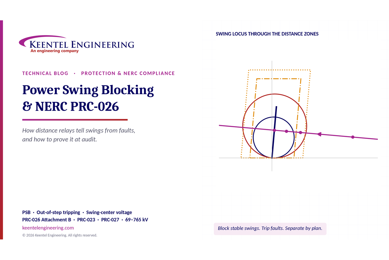
Power Swing Blocking, Out-of-Step Tripping and NERC PRC-026: How Distance Relays Tell Swings from Fa
By SANDIP R PATEL • November 14, 2026
Learn power swing blocking, out-of-step tripping, distance relay settings and NERC PRC-026 compliance with Keentel Engineering's technical guide.
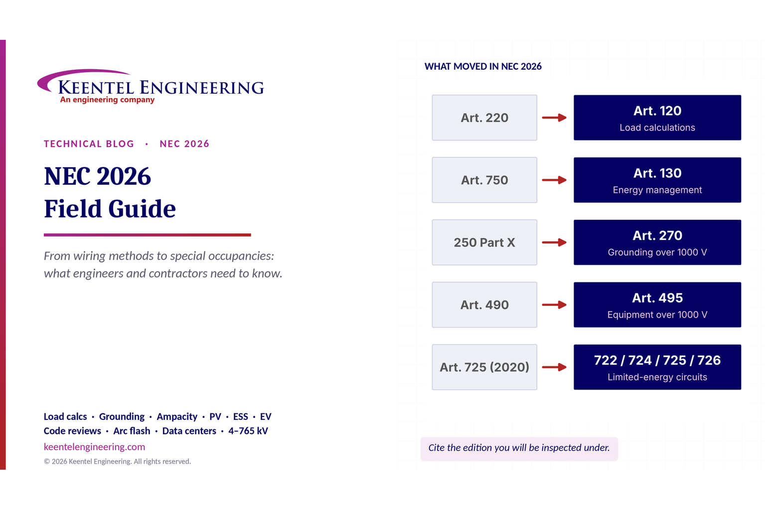
NEC 2026 Field Guide showing electrical code changes for load calculations, grounding, energy manage
By SANDIP R PATEL • November 14, 2026
Explore NEC 2026 changes to load calculations, grounding, ampacity, wiring, solar, ESS and EV systems with Keentel Engineering's practical field guide. Copy
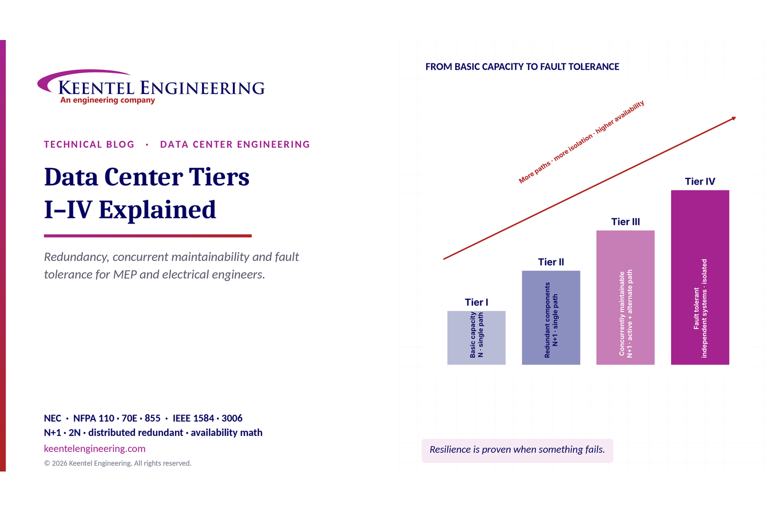
Data Center Tiers I–IV comparison showing redundancy, concurrent maintainability and fault tolerance
By SANDIP R PATEL • November 14, 2026
Explore Data Center Tiers I–IV, N+1 vs. 2N redundancy, concurrent maintainability, fault tolerance, and MEP design requirements with Keentel Engineering.
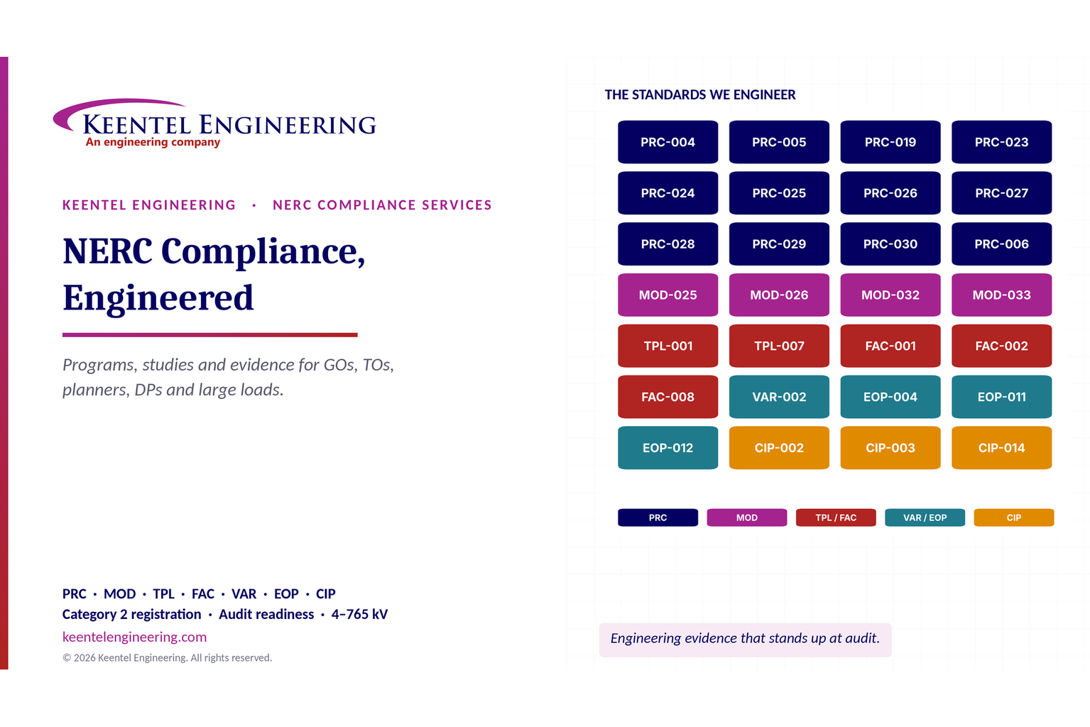
NERC compliance engineering standards covering PRC, MOD, TPL, FAC, VAR, EOP and CIP.
By SANDIP R PATEL • November 14, 2026
Explore NERC compliance engineering for generator and transmission owners, IBRs and large loads, covering PRC, MOD, TPL standards, audits and modeling.
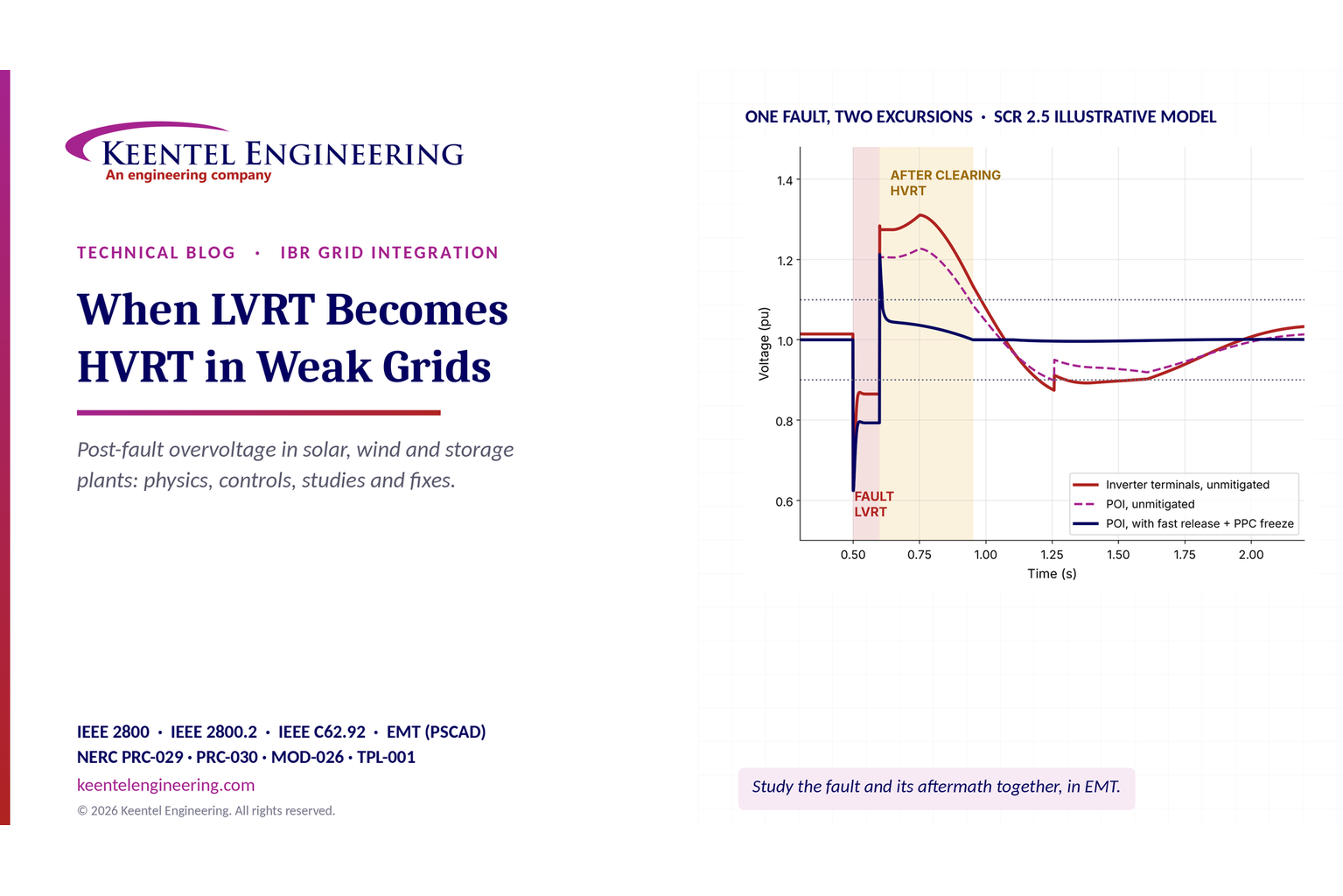
LVRT to HVRT transition in weak grids showing post-fault overvoltage and inverter voltage response.
By SANDIP R PATEL • November 14, 2026
Learn why LVRT becomes HVRT in weak grids, how post-fault overvoltage trips solar, wind and BESS plants, and how Keentel Engineering uses EMT studies.
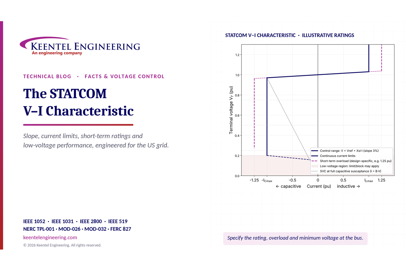
STATCOM V-I characteristic graph showing voltage regulation, current limits and short-term overload.
By SANDIP R PATEL • November 14, 2026
Explore STATCOM V-I characteristics, voltage control slope, current limits, short-term overload ratings, reactive power and low-voltage grid performance.
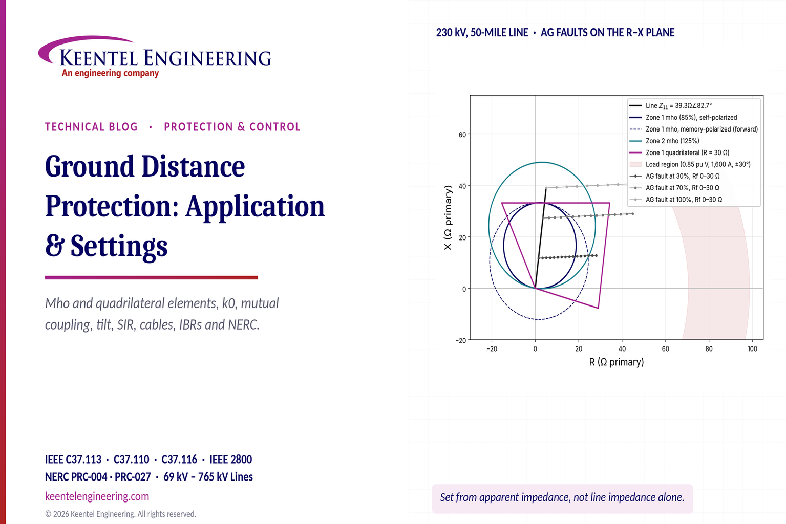
Ground distance protection R-X diagram showing mho and quadrilateral relay settings for a 230 kV lin
By SANDIP R PATEL • November 12, 2026
Learn ground distance protection settings for transmission lines: k0 compensation, mho and quadrilateral relays, mutual coupling and NERC compliance.
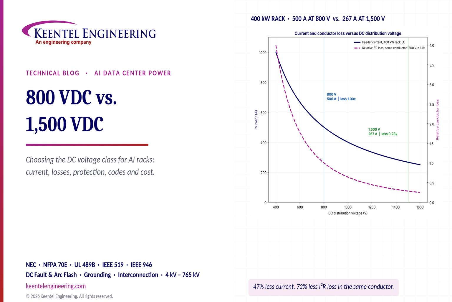
800 VDC vs. 1,500 VDC AI data center power distribution chart comparing rack current and conductor l
By SANDIP R PATEL • November 12, 2026
Compare 800 VDC vs. 1500 VDC for AI data centers. Explore efficiency, copper savings, DC protection, safety and power distribution with Keentel Engineering.
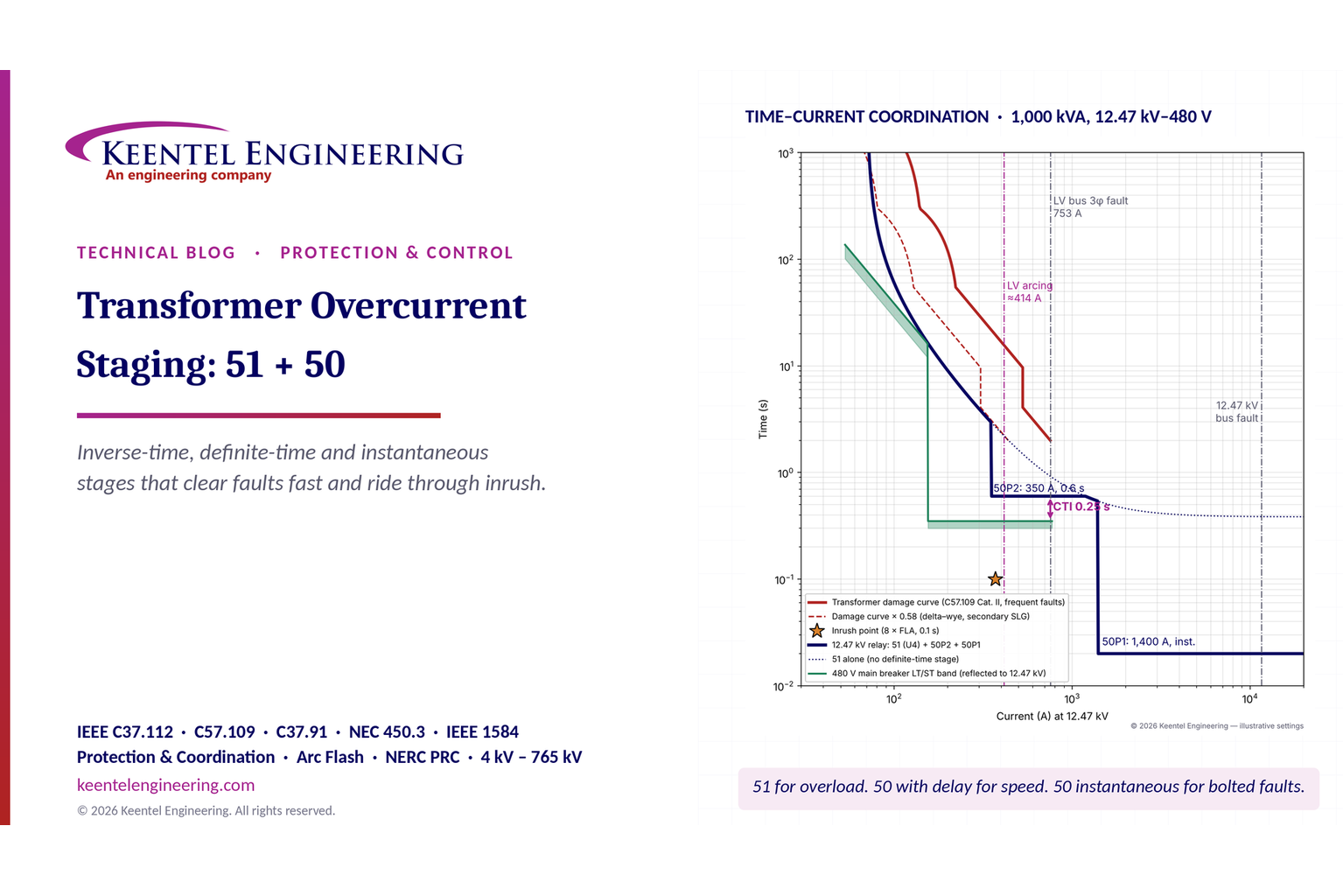
Transformer overcurrent protection 51/50 time-current coordination curves showing relay settings and
By SANDIP R PATEL • November 12, 2026
Learn transformer overcurrent protection using 50/51 relay stages, inverse-time curves, inrush checks, fault coordination and arc-flash mitigation.