


Explore essential NERC Alert 3 actions for IBRs. Learn how TOs, TPs, PCs & GOs must respond with updated models, criteria, and compliance strategies.

Explore advanced power system modeling for long-term planning. Learn about IRPs, demand forecasting, resource adequacy, resilience, and equity in energy.
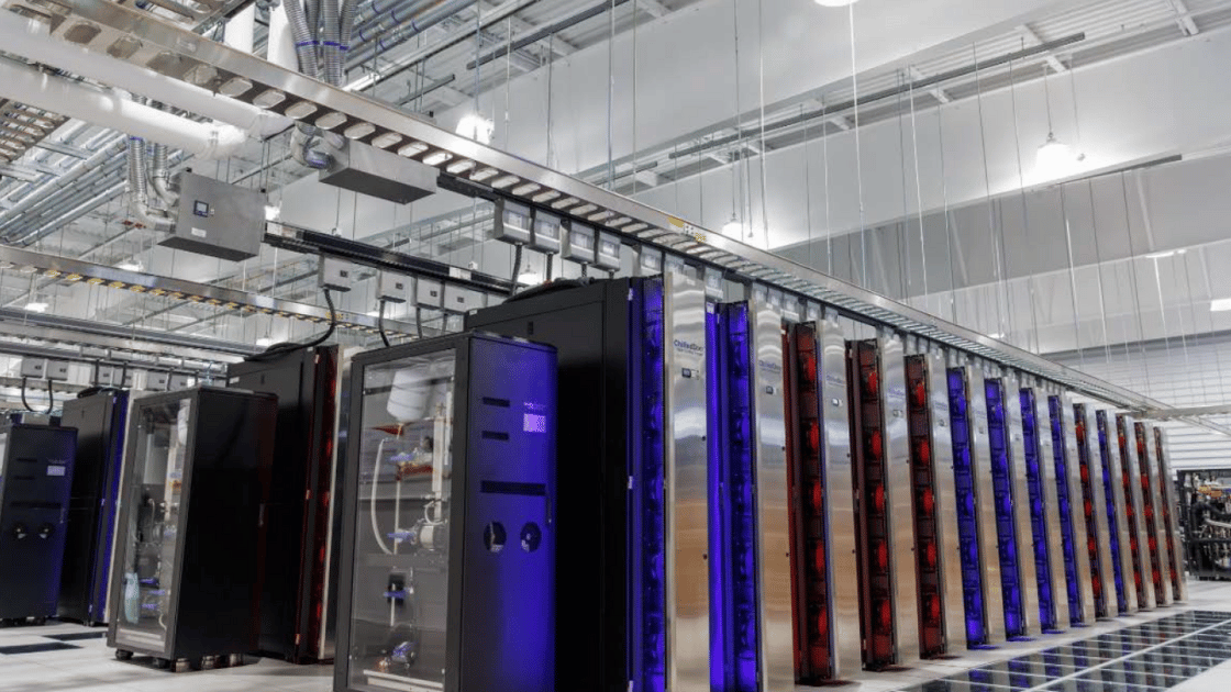
Learn how to reduce energy use, optimize cooling, and improve efficiency in data centers with the 2024 FEMP & NREL best practices guide.
Explore July 2025 grid reliability trends, IBR registration mandates, and NERC compliance updates. Stay ahead with Keentel’s future-ready engineering insights.
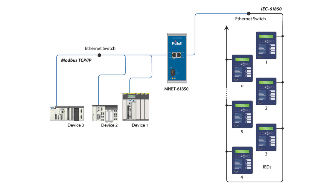
Enable seamless Modbus to IEC 61850 integration with the PLX82-MNET-61850 gateway. Achieve NERC compliance with audit-ready substation communication.
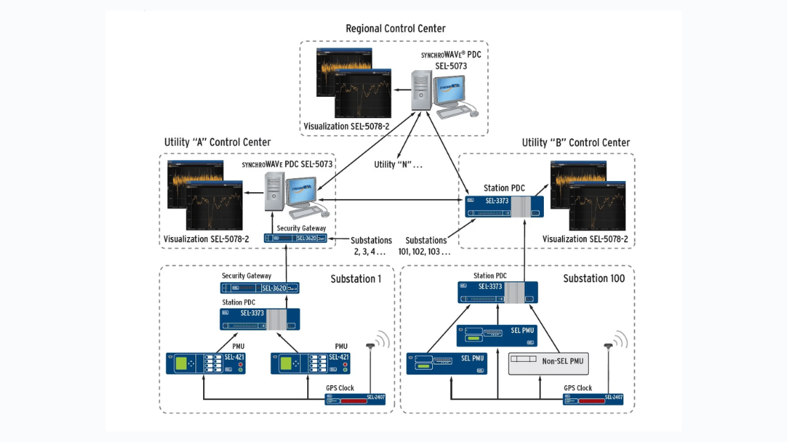
Discover how SEL synchrophasor systems, including the SEL-487E PMU, support real-time power grid monitoring and NERC PRC-002-2 compliance. Learn more with Keentel.

Explore NERC PRC-029-1 ride-through requirements for inverter-based resources (IBRs). Learn how it enhances grid reliability with FERC Order No. 901 support.
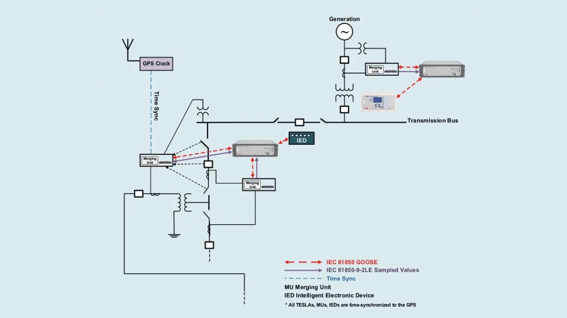
Ensure NERC PRC-028 compliance with TESLA 4000 and Keentel Engineering’s expert integration, monitoring, and audit support services for utilities and GOs.
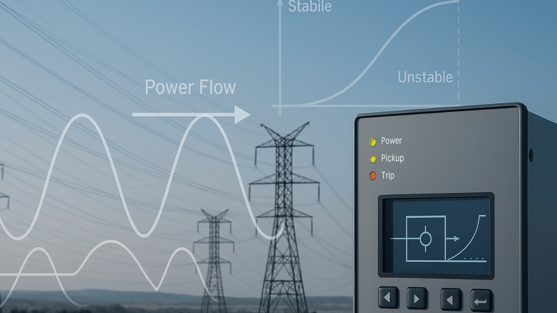
Ensure your relays don’t trip during stable power swings. Learn how PRC-026 compliance works, what relays it applies to, and how to automate your evaluations.


