A Coordinated Electric System Interconnection Review—the utility’s deep-dive on technical and cost impacts of your project.
Challenge: Frequent false tripping using conventional electromechanical relays
Solution: SEL-487E integration with multi-terminal differential protection and dynamic inrush restraint
Result: 90% reduction in false trips, saving over $250,000 in downtime
Utility Scale Battery Energy Storage Systems (BESS): A Complete Guide to Voltage and Frequency Ride-Through Analysis
October 27, 2025 | Blog
1. Introduction: The New Era of Grid Compliance
The rapid growth of renewable energy and inverter-based resources (IBRs) has transformed the power industry’s operating landscape. Today, large-scale Battery Energy Storage Systems (BESS) are no longer passive grid participants, they are active, responsive assets that must comply with stringent performance and stability standards.
At the forefront of these standards is IEEE Std 2800™-2022, which establishes the technical requirements for grid-connected inverter-based resources to ensure voltage and frequency ride-through (VRT/FRT) capabilities, dynamic reactive power support, and coordination with protection systems.
For developers, engineers, and utilities, achieving IEEE 2800 compliance isn’t just a regulatory checkbox, it’s a proof of reliability, interoperability, and system resilience.
2. Understanding IEEE 2800-2022 and NERC Standards
2.1 IEEE P2800-2022 Overview
IEEE 2800-2022 defines performance-based criteria for large-scale inverter-based generation facilities, including:
- Solar PV
- Wind
- Battery Energy Storage Systems
- Hybrid inverter systems
It specifies how these facilities should respond to voltage and frequency disturbances, ensuring stability and continuous operation during grid events.
2.2 Integration with NERC Standards
IEEE 2800 does not exist in isolation — it directly complements NERC’s compliance framework:
- NERC PRC-024-3: Defines voltage and frequency protective relay settings for generator owners.
- NERC MOD-032/033: Establishes data and model validation requirements for planning and operational studies.
By aligning with these standards, BESS owners can achieve holistic compliance while supporting Bulk Electric System (BES) reliability.
3. Why Ride-Through Compliance Matters for BESS
Voltage and frequency ride-through capabilities ensure that BESS remain online during transient events — supporting grid recovery rather than disconnecting at the first sign of disturbance.
Non-compliance risks include:
- Premature disconnection leading to cascading outages.
- FERC/NERC non-compliance penalties.
- Reduced project bankability and interconnection approval delays.
A compliant BESS can:
- Inject reactive power to support grid voltage.
- Modulate active power to counter frequency deviations.
- Enhance overall system inertia and damping, acting as a stabilizing force.
4. Voltage Ride-Through (VRT) Explained
Voltage ride-through defines how long a resource must stay connected under varying voltage magnitudes.
Key Regions (per IEEE 2800 Figure 4):
- Continuous Operation Region: 0.9–1.1 p.u. voltage.
- Mandatory Operation Region: 0.3–0.9 p.u. for specified durations (up to 20 sec).
- No Trip Zone: During transient voltage dips below 0.3 p.u. for <0.15 sec.
During VRT analysis, simulation tools (PSSE, PowerFactory, PSCAD) model fault conditions at the Point of Interconnection (POI) to confirm that the BESS controller does not trigger protection trips and responds per IEEE limits.
5. Frequency Ride-Through (FRT) Explained
Frequency ride-through specifies how long a BESS must remain in operation during frequency deviations.
Continuous Operation Range:
- 59.5 to 60.5 Hz (for 60 Hz systems).
Mandatory Ride-Through Range:
- Down to 57.0 Hz and up to 61.8 Hz for short durations.
FRT simulations apply step or ramp frequency events to verify inverter control logic, droop response, and active power modulation.
6. Interfacing IEEE 2800 with NERC PRC-024-3, MOD-032, and MOD-033
IEEE 2800 closely integrates with several key NERC standards — PRC-024-3, MOD-032, and MOD-033 — to create a unified framework for grid compliance and reliability. NERC PRC-024-3 ensures that generator protection systems do not trip during allowable voltage and frequency excursions, directly aligning relay trip curves with the ride-through windows defined by IEEE 2800.
NERC MOD-032 focuses on model data submission for planning studies, requiring the use of validated dynamic models such as REGC_A and REEC_A to represent generation resources accurately. NERC MOD-033, on the other hand, validates the correlation between actual system performance and simulation models, confirming that real event data aligns with expected model responses.
Collectively, these standards form a cohesive compliance ecosystem that ensures both operational performance and modeling accuracy for inverter-based and synchronous resources.
Read more about
Nerc Voltage Sensitive Loads
7. Step-by-Step Compliance Analysis Workflow
Step 1: Model Development
- Obtain inverter dynamic models from OEM (PSSE/PSCAD format).
- Validate parameters against IEEE 2800 Annex A requirements.
Step 2: System Integration
- Embed BESS into regional transmission models.
- Verify steady-state power flow, reactive capabilities, and POI voltage.
Step 3: Fault Simulation and Ride-Through Testing
- Conduct 3-phase and SLG faults.
- Record voltage recovery and BESS current response.
- Confirm no premature trip.
Step 4: Frequency Event Testing
- Apply frequency ramps (±2 Hz).
- Validate active power control (P–f curve) and droop functionality.
Step 5: Protection Coordination
- Verify under/over-voltage and frequency relay settings are outside IEEE 2800 mandatory ride-through zones.
Step 6: Validation & Reporting
- Document simulation plots, parameter tables, and compliance conclusions.
8. Simulation and Modeling Tools Used in Compliance Studies
A range of advanced simulation and modeling tools are used to perform compliance studies for IEEE 2800. Each software platform serves a specific function, helping engineers evaluate dynamic performance, protection coordination, and control behavior under grid disturbance scenarios.
PSSE and TSAT are primarily used for RMS simulations and transient stability analyses. These tools help verify voltage and frequency ride-through capabilities, ensuring that generation resources maintain stability during grid events.
PSCAD/EMTDC is used for electromagnetic transient (EMT) simulations. It provides detailed insights into fast inverter dynamics and low-voltage ride-through (LVRT) behavior, allowing engineers to validate the rapid response characteristics of inverter-based resources.
DigSILENT PowerFactory combines both RMS and EMT modeling capabilities, making it suitable for end-to-end compliance studies. It allows integration of system-level and component-level analyses within a single environment, ensuring comprehensive validation of IEEE 2800 requirements.
MATLAB/Simulink supports control-level analysis, enabling detailed testing of inverter control strategies such as droop control, phase-locked loop (PLL) performance, and frequency response behavior.
RTDS and HYPERSIM are real-time digital simulation platforms used for Hardware-in-the-Loop (HIL) testing. These tools allow physical validation of control logic and real-time response under simulated grid disturbances, bridging the gap between software-based studies and field performance.
ETAP and ASPEN OneLiner are employed for protection coordination studies. They help analyze relay settings, trip logic, and overall system coordination to ensure that protection systems align with IEEE 2800’s non-tripping requirements during transient events.
9. Data Validation and Model Verification Requirements
IEEE 2800 requires a demonstrated match between:
- Simulated inverter response, and
- Measured field test data or HIL test outputs.
This ensures models represent actual field behavior under transient conditions.
10. Preparing the IEEE 2800 Compliance Report
A well-structured IEEE 2800 Compliance Report is essential for demonstrating full adherence to performance, modeling, and validation requirements. It must provide traceable evidence that all simulations, test results, and equipment settings align with the standard’s technical criteria.
Modeling Methodology
Here, the report describes the modeling approach, including the simulation tools used (e.g., PSSE, PSCAD, DigSILENT), key assumptions, model parameters, and data sources. This section ensures transparency in how system dynamics and control interactions were represented.
Voltage Ride-Through Results:
This section presents the simulation cases designed to test voltage ride-through (VRT) performance under different grid disturbance conditions. Voltage profiles, event durations, and performance graphs are included to illustrate compliance with IEEE 2800’s voltage tolerance curves.
Frequency Ride-Through Results:
Detailed frequency response plots and analyses are provided here to verify the generator’s ability to remain connected during frequency deviations. This demonstrates alignment with frequency ride-through (FRT) requirements.
Control and Protection Review:
This part reviews inverter and relay settings to confirm that protection logic does not conflict with IEEE 2800 ride-through windows. It includes relay coordination results, inverter control setpoints, and logic diagrams if available.
Model Validation:
This section presents the comparison between simulated and test-based performance results. Validation charts, response curves, and measured data comparisons help demonstrate the model’s accuracy and reliability.
Compliance Summary:
A tabulated compliance matrix summarizes the findings for each IEEE 2800 requirement, indicating whether the resource meets, exceeds, or requires mitigation for specific criteria.
Engineer’s Attestation:
The final section provides a Professional Engineer (PE)-sealed statement verifying the accuracy of the study and attesting that the resource meets all applicable IEEE 2800 compliance requirements.
Together, these sections form a complete, traceable, and audit-ready compliance report — a key deliverable in ensuring that all generation resources are grid-ready and aligned with evolving interconnection standards.
11. Example: 100 MW Battery Energy Storage Compliance Case
Scenario:
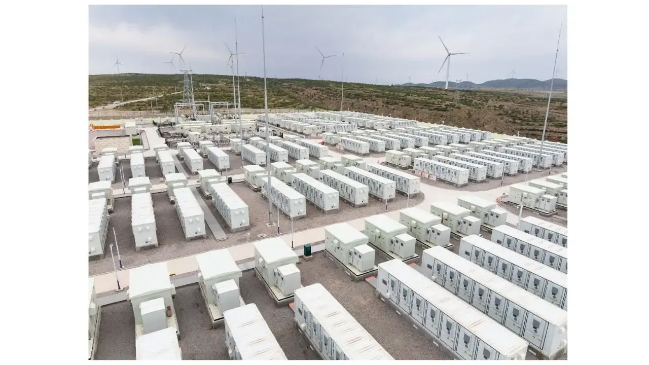
A 100 MW / 200 MWh lithium-ion BESS interconnecting to a 230 kV substation.
Findings:
- Stayed online during 0.35 p.u. voltage sag for 0.12 sec (compliant).
- Frequency dip to 58.4 Hz sustained for 5 sec — system remained connected.
- Reactive power injected within 1 cycle of disturbance detection.
- Relay coordination validated per PRC-024-3.
Result:
Fully compliant with IEEE 2800 and NERC PRC standards.
12. Common Technical Challenges in Ride-Through Analysis
- Incomplete inverter model data from OEMs.
- Misalignment between field settings and simulation assumptions.
- Relay coordination overlaps causing false trips.
- Underestimation of PLL instability in EMT-level simulations.
- Inadequate documentation for ISO submission.
Keentel Engineering mitigates these through model validation workflows, OEM coordination, and independent verification.
13. Keentel Engineering’s Approach to IEEE 2800 Compliance
At Keentel Engineering, we specialize in grid integration and compliance analysis for renewable and storage projects across North America.
Our compliance process includes:
- Full IEEE 2800 and NERC PRC analysis (PRC-024, PRC-019, PRC-026).
- Model building in PSSE, TSAT, and PSCAD.
- Hardware-in-the-loop validation.
- Relay coordination studies using ETAP and ASPEN.
- Preparation of ISO/RTO submission-ready compliance reports.
Our multidisciplinary expertise ensures your BESS project achieves technical credibility, regulatory compliance, and seamless interconnection approval.
14. Key Takeaways and Best Practices
- Always verify both VRT and FRT curves using multiple simulation platforms.
- Align all inverter and relay settings with IEEE 2800 boundaries.
- Validate models through real test or HIL data.
- Keep compliance documentation traceable and transparent.
- Engage with your ISO and transmission planner early to avoid rework.
Frequently Asked Questions
1. What is the main purpose of IEEE 2800-2022?
To ensure large-scale inverter-based resources remain connected and support grid stability during voltage and frequency disturbances.
2. Does IEEE 2800 apply to battery energy storage systems?
Yes. It applies to any inverter-based generation, including standalone and hybrid BESS installations.
3. How is voltage ride-through (VRT) tested?
By simulating voltage dips (faults) at the POI using tools like PSSE or PSCAD and observing the inverter’s response against IEEE-defined curves.
4. What are the key VRT thresholds?
Continuous: 0.9–1.1 p.u.
Mandatory: 0.3–0.9 p.u. (duration dependent).
5. How is frequency ride-through (FRT) validated?
Using frequency ramp or step events to confirm the BESS remains connected between 57–61.8 Hz as required.
6. What are typical frequency thresholds for 60 Hz systems?
Continuous operation: 59.5–60.5 Hz;
Mandatory ride-through: 57–61.8 Hz.
7. What is the relationship between IEEE 2800 and PRC-024-3?
PRC-024 ensures protective settings don’t conflict with IEEE 2800’s ride-through boundaries.
8. What software tools are used for compliance?
PSSE, TSAT, PSCAD, PowerFactory, ETAP, ASPEN, MATLAB/Simulink, and RTDS.
9. What type of models are required for submission?
Validated dynamic models such as REGC_A, REEC_A, and REPCA_A, per MOD-032.
10. What is the role of MOD-033?
It ensures that actual event data matches simulated model responses — validating model accuracy.
11. How are inverter control loops tested?
By applying small-signal disturbances and analyzing P-f and Q-V response curves.
12. How does a BESS contribute to system recovery after faults?
Through reactive power injection and active power modulation, improving voltage and frequency stability.
13. What is a typical compliance report length?
Generally 50–100 pages including simulations, tables, and validation plots.
14. How are protection settings reviewed?
All relay trip curves are compared against IEEE 2800 voltage and frequency limits.
15. What happens if BESS trips within mandatory ride-through limits?
It’s considered non-compliant and may lead to required retesting or interconnection delays.
16. What’s the advantage of EMT-level modeling?
It captures high-frequency control dynamics and converter behavior that RMS models may miss.
17. How long does a compliance study typically take?
4–8 weeks depending on data availability and simulation scope.
18. Who approves compliance results?
Typically, the Transmission Planner, Balancing Authority, or ISO/RTO (e.g., ERCOT, PJM, CAISO).
19. What if OEM data is confidential?
Keentel Engineering signs NDAs to model proprietary controls while maintaining compliance transparency.
20. How is HIL testing performed?
By connecting inverter controllers to RTDS/HYPERSIM systems and simulating real grid events.
21. How often should ride-through settings be reviewed?
Every 3–5 years or after major firmware/control updates.
22. Can IEEE 2800 replace PRC-024-3 compliance?
No — they complement each other; both must be met.
23. What are the deliverables of a Keentel compliance report?
Simulation data, compliance matrices, relay coordination summary, and a PE-sealed conclusion.
24. What’s the difference between PSSE and PSCAD analyses?
PSSE is RMS (long-term stability), while PSCAD captures EMT-level transients and fast inverter controls.
25. Why partner with Keentel Engineering for IEEE 2800 compliance?
Keentel offers multidisciplinary expertise, end-to-end simulation, model validation, and proven experience in NERC/IEEE compliance across renewable and BESS projects

About the Author:
Sonny Patel P.E. EC
IEEE Senior Member
In 1995, Sandip (Sonny) R. Patel earned his Electrical Engineering degree from the University of Illinois, specializing in Electrical Engineering . But degrees don’t build legacies—action does. For three decades, he’s been shaping the future of engineering, not just as a licensed Professional Engineer across multiple states (Florida, California, New York, West Virginia, and Minnesota), but as a doer. A builder. A leader. Not just an engineer. A Licensed Electrical Contractor in Florida with an Unlimited EC license. Not just an executive. The founder and CEO of KEENTEL LLC—where expertise meets execution. Three decades. Multiple states. Endless impact.
Services

Let's Discuss Your Project
Let's book a call to discuss your electrical engineering project that we can help you with.

About the Author:
Sonny Patel P.E. EC
IEEE Senior Member
In 1995, Sandip (Sonny) R. Patel earned his Electrical Engineering degree from the University of Illinois, specializing in Electrical Engineering . But degrees don’t build legacies—action does. For three decades, he’s been shaping the future of engineering, not just as a licensed Professional Engineer across multiple states (Florida, California, New York, West Virginia, and Minnesota), but as a doer. A builder. A leader. Not just an engineer. A Licensed Electrical Contractor in Florida with an Unlimited EC license. Not just an executive. The founder and CEO of KEENTEL LLC—where expertise meets execution. Three decades. Multiple states. Endless impact.
Leave a Comment
We will get back to you as soon as possible.
Please try again later.

