


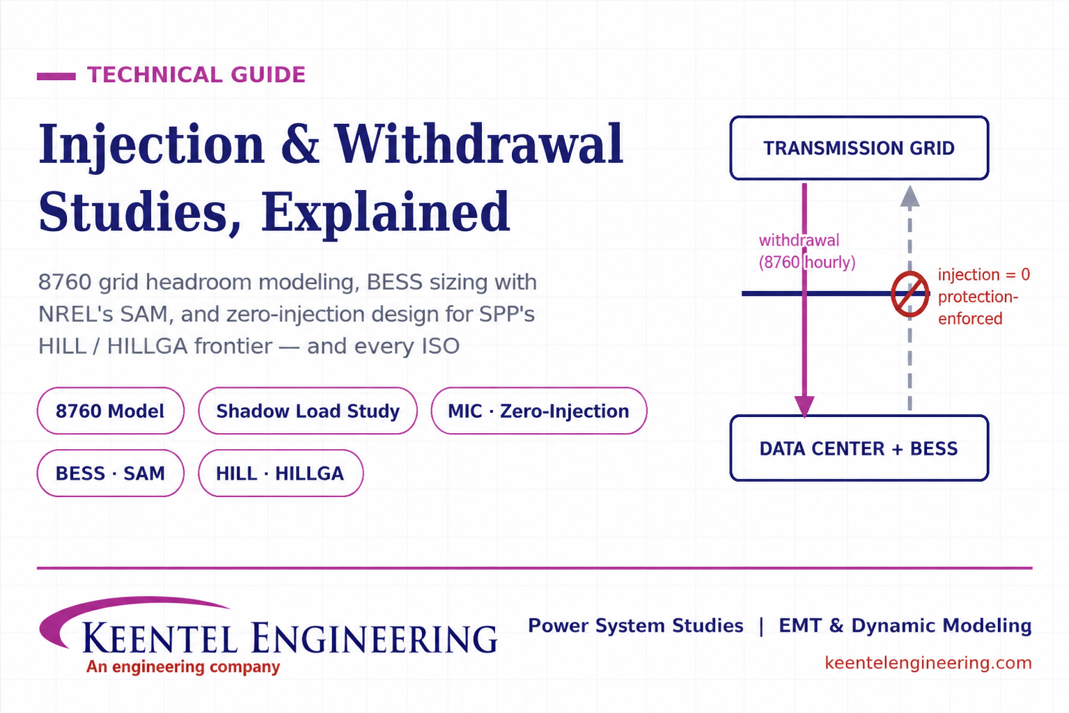
Learn how injection and withdrawal studies, 8760 headroom modeling, zero-injection engineering, and SPP HILLGA improve large load grid interconnections
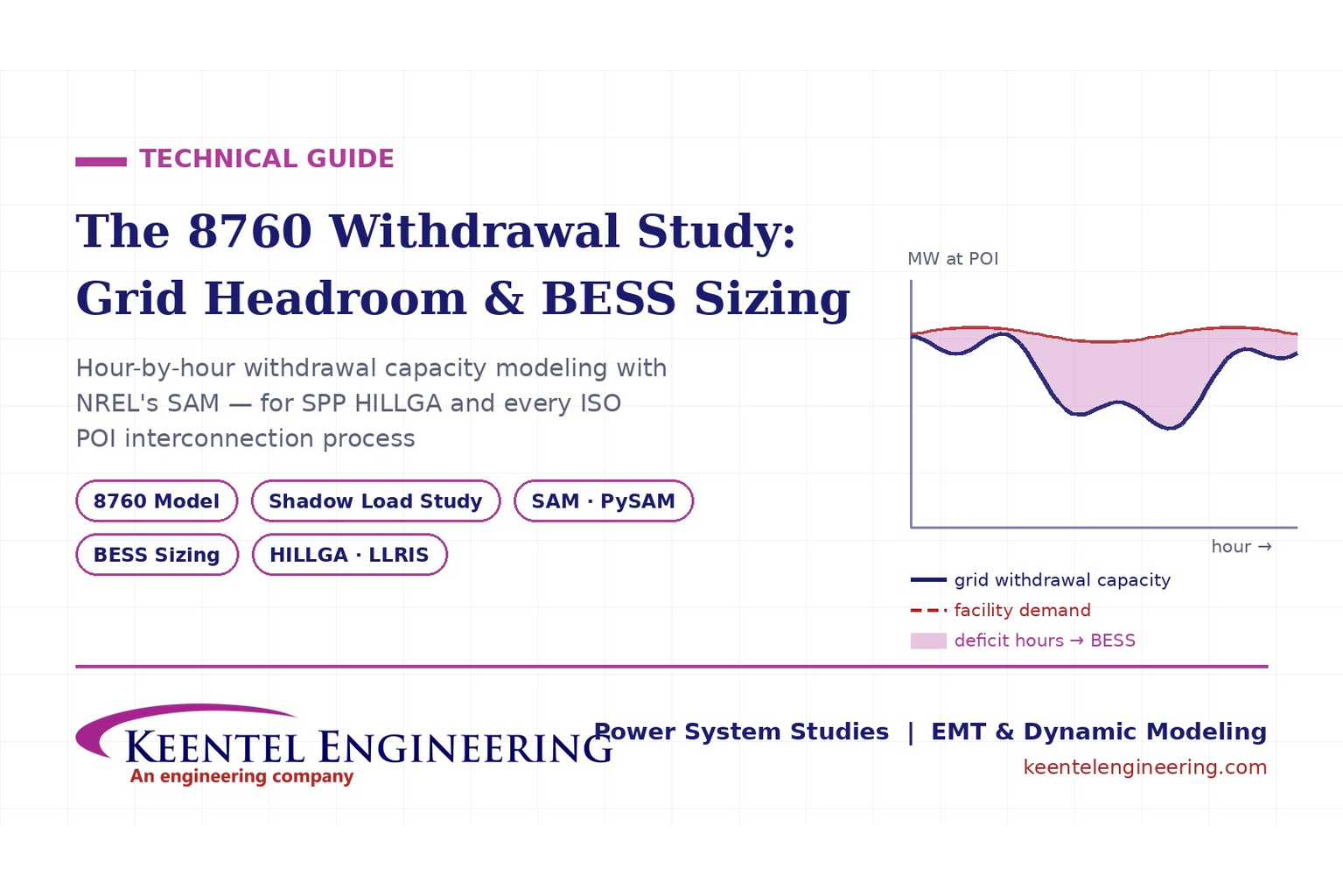
Learn how an 8760 withdrawal study models hourly grid headroom and uses SAM-based BESS sizing for large-load interconnection projects.
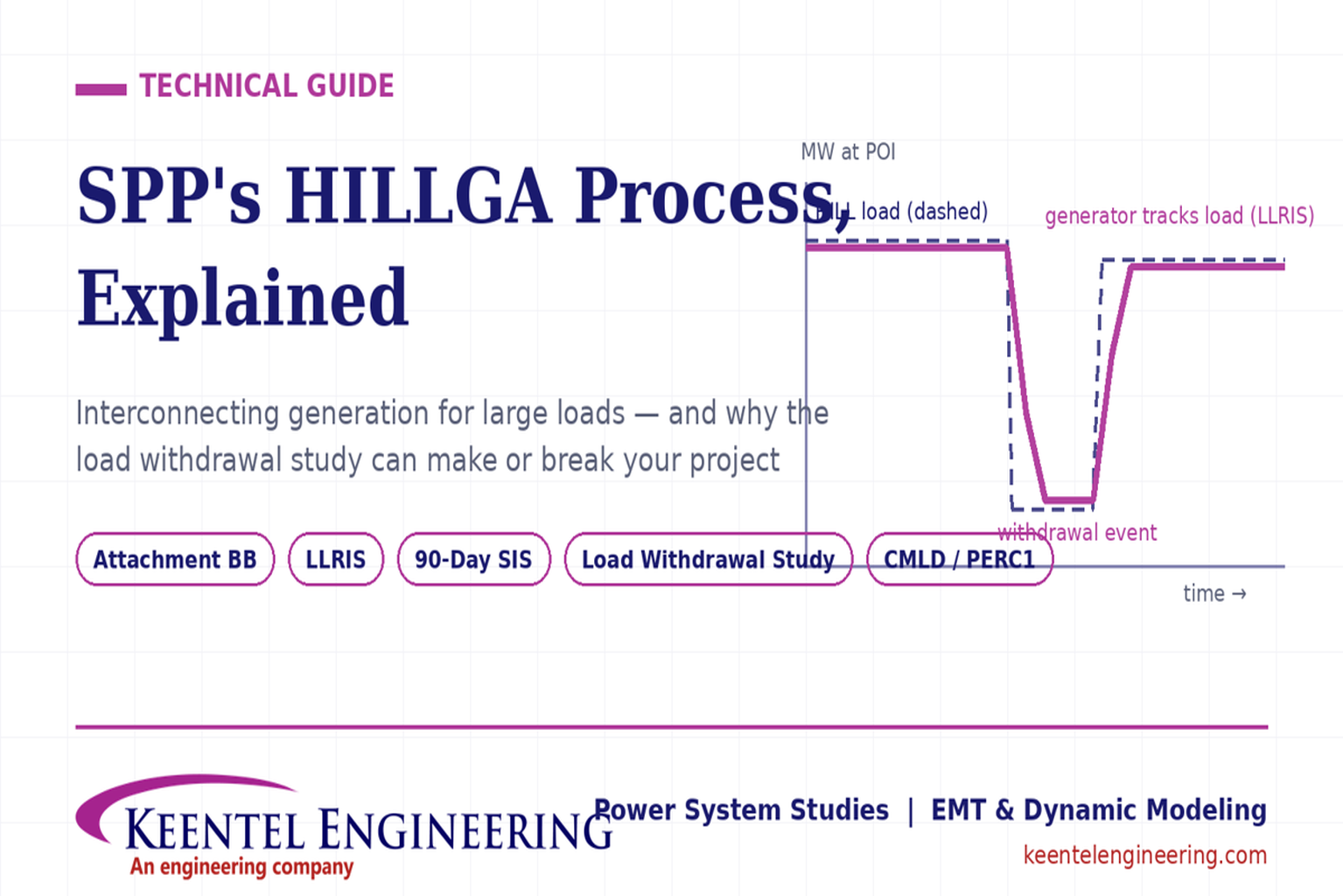
Learn how the SPP HILLGA process supports data center generation interconnection and why an 8760 withdrawal study can determine project success.
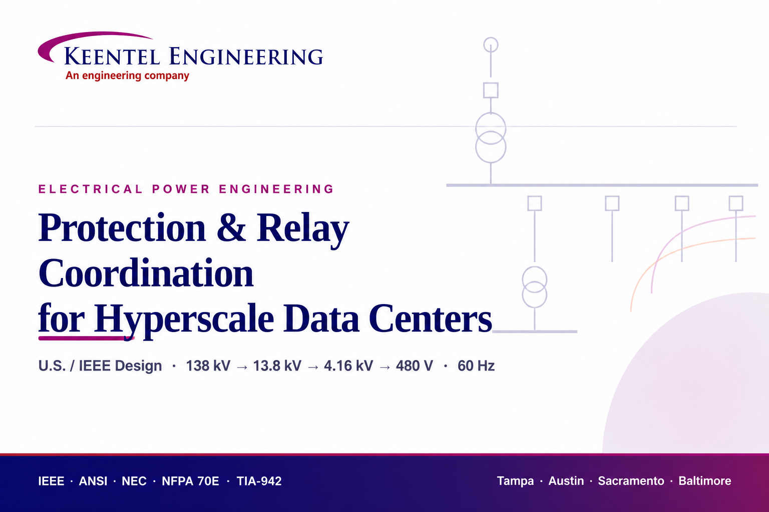
Learn electrical protection and relay coordination for hyperscale data centers with IEEE standards, short-circuit studies, arc-flash analysis, and MV protection.
Explore Battery Energy Storage System components, including cells, PCS, BMS, EMS, cooling, fire protection, sizing, safety, and grid codes.
Explore how grid-forming inverters support BESS, synthetic inertia, grid-code compliance, plant sizing, testing, and project revenue.
Learn how SEL RTAC protection monitoring supports NERC PRC-005 compliance, predictive maintenance alarms, automated reporting, and relay verification.
Explore utility-scale BESS design from the 10% package to IFC, NFPA 855 compliance, PSS®E/PSCAD models, and ERCOT interconnection.
Substation design guide, electrical substation design, substation equipment sizing, IEEE 80 grounding design, IEEE 998 lightning shielding, bus configuration design


