1. Executive Summary
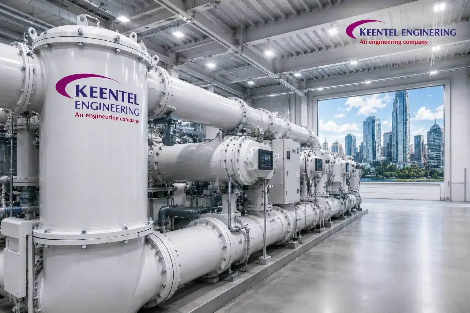
Keentel Engineering Solutions provided owner's engineering and detailed electrical design for a new 220/33 kV indoor gas-insulated switchgear (GIS) substation built on a severely constrained parcel inside a high-density commercial district. The Utility held no land reserve in the load centre, planning consent prohibited visible outdoor electrical plant, and atmospheric pollution combined with airborne salt and industrial particulate made exposed outdoor insulation an unacceptable reliability risk.
The delivered asset is a fully enclosed, building-integrated substation on three occupied levels. The 220 kV switching plant is a double busbar with bus coupler GIS arrangement rated 63 kA for 3 s, supplied by four underground 220 kV XLPE cable circuits. Three 150 MVA 220/33 kV transformers at 13.5% impedance feed 33 kV indoor metal-clad switchgear operated in three normally segregated sections. Both sides are entirely cable-connected; there is no overhead line termination and no outdoor high-voltage bus.
The governing achievement was footprint. An air-insulated (AIS) arrangement of equivalent capability was assessed at approximately 9,000 m² of net electrical yard against 1,450 m² for the delivered GIS solution — a reduction of roughly 84%, and the difference between a feasible project and no project.
Keentel's scope covered the full analytical package: load flow and N-1 / N-1-1 contingency assessment in PSS®E; short-circuit analysis to IEC 60909 supporting the 63 kA rating decision; electromagnetic transient studies in PSCAD/EMTDC covering very fast transient overvoltages (VFTO), cable energization and the zero-missing phenomenon, transformer inrush and breaker restrike; insulation coordination to IEC 60071 with arrester energy duty verification; harmonic and resonance screening; IEEE 80 grounding for a building-integrated earth mesh bonded to structural steel; IEEE 693 seismic qualification; SF6 dispersion and ventilation modelling; and boundary compliance for noise and magnetic field against ICNIRP reference levels. DIgSILENT PowerFactory and ETAP were used for cross-validation, auxiliary design and arc flash assessment.
The station meets a modelled availability of 99.994% at the 33 kV busbars, achieved 2.4 pC maximum partial discharge against a 5 pC criterion, and carries an expansion path to two further bays.
Figures presented are representative of the delivered design and have been generalized to protect client confidentiality.
Project at a Glance
| Parameter | Value |
|---|---|
| Asset type | Indoor building-integrated GIS substation, 220/33 kV |
| 220 kV configuration | Double busbar with bus coupler, 10 equipped bays, 2 spare positions |
| Transformation capacity | 3 x 150 MVA, 220/33 kV, 13.5% impedance |
| Short-circuit rating | 63 kA / 3 s at 220 kV; 31.5 kA / 3 s at 33 kV |
| Footprint | 1,450 m² GIS versus approx. 9,000 m² AIS equivalent |
| Modelled availability | 99.994%, approx. 31 minutes/year unavailability |
| Keentel role | Owner's engineer, system studies, detailed design, commissioning support |
2. Project Context and Business Drivers
District demand had grown at roughly 5.5% per annum against two 220/33 kV points of supply on the periphery. Loss of either during summer peak overloaded the surviving 33 kV feeders within twenty minutes and forced rotational shedding under an N-1-1 event. A third injection point inside the load centre was the only sound remedy; reinforcing from the periphery would have required an unbuildable number of new duct routes through congested streets.
Land governed everything that followed. The only available parcel measured approximately 38 m by 46 m with an irregular boundary, enclosed on three sides by occupied buildings. A ten-bay 220 kV double busbar AIS arrangement with three transformer bays, firewalls and oil containment could not be compressed below roughly 9,000 m². The parcel was one fifth of that.
Three further drivers reinforced the decision independently of land. Pollution surveys placed equivalent salt deposit density in the very heavy band of IEC 60815, implying specific creepage of 31 mm/kV or more, an aggressive washing regime and persistent flashover risk at first rain; gas-insulated equipment removes exposed insulation from the problem entirely. Planning consent required invisible plant, a matching façade and night-time boundary noise below 45 dB(A). And the district's concentration of data-handling, financial and healthcare load led the Owner to set an availability target better than 99.99% at the 33 kV busbars, which constrained the bus scheme selection.
The commercial case closed on land value: avoiding acquisition of approximately 7,550 m² exceeded the entire capital premium of GIS over AIS several times over.
3. Design Basis and Technical Requirements
The design basis was issued in the first eight weeks as a controlled document governing all vendor and contractor submissions.
3.1 Electrical and environmental design criteria
| Criterion | Design value |
|---|---|
| Nominal / highest system voltage (HV) | 220 kV / 245 kV |
| Nominal / highest system voltage (MV) | 33 kV / 36 kV |
| Rated frequency | 50 Hz |
| HV rated short-circuit / peak withstand | 63 kA, 3 s / 173 kA peak |
| MV rated short-circuit / peak withstand | 31.5 kA, 3 s / 82 kA peak |
| HV lightning / power-frequency withstand | 1050 kV BIL / 460 kV, 1 min |
| MV lightning / power-frequency withstand | 170 kV BIL / 70 kV, 1 min |
| System earthing | Solidly earthed at 220 kV; 33 kV via 1000 A NER |
| Ambient design temperature | 45 °C maximum; 50 °C indoor switchroom design |
| Pollution severity | IEC 60815 class e, very heavy; outdoor plant excluded |
| Seismic qualification | IEEE 693 High performance level, 0.5 g ZPA |
| SF6 leakage rate | ≤ 0.5% per compartment per year, IEC 62271-203 |
| Boundary noise limit | 45 dB(A) night-time at property line |
| Availability target | ≥ 99.99% at 33 kV busbars |
3.2 Standards register
| Standard | Application in this design |
|---|---|
| IEC 62271-203 | Gas-insulated metal-enclosed switchgear above 52 kV |
| IEC 62271-100 / -102 | Circuit breakers; disconnectors and earthing switches |
| IEC 62271-200 | Metal-enclosed switchgear 1–52 kV, internal arc classification |
| IEC 60071-1 / -2 | Insulation coordination, principles and application |
| IEC 60909-0 | Short-circuit current calculation |
| IEC 60287 / IEC 60853 | Cable current rating, steady state and cyclic |
| IEEE 835 | Power cable ampacity tables, independent cross-check |
| IEC 60270 | Partial discharge measurement |
| IEC 62271-4 | Handling procedures for SF6 and its mixtures |
| IEC 62067 / IEC 60840 | Extruded cables and accessories |
| IEEE 80 / EN 50522 | Substation grounding and earthing safety |
| IEEE 693 | Seismic design of substations |
| IEC 61850 | Substation automation communication networks |
| IEEE 1584 | Arc flash hazard calculation, auxiliary systems |
| IEEE 1115 | Sizing of nickel-cadmium batteries |
| ICNIRP | Public exposure limits, time-varying magnetic fields |
| ISO 14520 | Clean agent fire extinguishing systems |
The Owner additionally required that all high-voltage plant be maintainable without a full station outage, that expansion to two further bays be possible without cutting into energized gas sections, that no transformer oil escape the building envelope, and that SF6 inventory be tracked to the gram.
4. Substation Configuration and Single-Line Architecture
4.1 Bus scheme trade-off
Four arrangements were compared using a reliability block model, a maintainability assessment reflecting the realities of working on a sealed gas-insulated assembly, and normalized cost per bay including building volume. Failure rates came from published international GIS service surveys, with 168 hours mean time to repair for a gas-compartment failure.
| Scheme | CB per circuit | Modelled unavailability | Relative cost/bay | Assessment |
|---|---|---|---|---|
| Single busbar, sectionalized | 1.0 | 4.1 x 10⁻⁴ | 1.00 | Rejected; bus fault or maintenance removes half the station |
| Double busbar with bus coupler | 1.0 | 5.6 x 10⁻⁵ | 1.24 | Selected; best availability per unit cost and volume |
| One-and-a-half breaker | 1.5 | 3.9 x 10⁻⁵ | 1.87 | Rejected; marginal gain, 41% more building volume |
| Ring bus, 10 positions | 1.0 | 2.7 x 10⁻⁴ | 1.09 | Rejected; degrades at high bay count, expansion breaks ring |
Against single busbar, double busbar removes the dominant unavailability contributor. A sealed GIS busbar is extremely reliable, but when a compartment fails the repair is long and a single-busbar station has no redundant bus on which to continue serving load. The modelled 7:1 improvement cost a 24% premium per bay.
Against one-and-a-half breaker, the analysis produced the result that most often surprises stakeholders: the availability advantage is small. The busbar failure rate the scheme defends against is already low in GIS, while it adds 50% more circuit breakers, each itself a failure source. The modelled difference was 1.7 x 10⁻⁵, about nine minutes per year, purchased for a 51% cost increase and 41% more hall volume.
Against ring bus, the ten-position requirement was decisive. Ring reliability degrades as position count rises, because a second contingency during maintenance splits the ring into isolated arcs, and adding a bay means breaking the ring — in GIS, gas recovery from adjacent compartments and an extended outage.
4.2 Delivered arrangement
| Bay function | Quantity | Notes |
|---|---|---|
| 220 kV incoming cable feeder | 4 | Two from each of two independent grid sources |
| 220 kV transformer bay | 3 | One per 150 MVA transformer |
| 220 kV bus coupler | 1 | Independent CT sets both sides |
| 220 kV bus VT / earthing bay | 2 | One per busbar |
| 220 kV spare bay position | 2 | Bus extension terminated at blanked gas barrier |
| 33 kV incomer | 3 | Cable-connected from transformer MV terminations |
| 33 kV bus section breaker | 2 | Normally open, automatic transfer enabled |
| 33 kV outgoing feeder | 24 | Eight per section |
| 33 kV auxiliary transformer feeder | 2 | Station service, from separate sections |
Each 220 kV bay comprises three-position busbar selection, a single-break SF6 circuit breaker, line and busbar disconnectors, a maintenance earthing switch, a fast-acting earthing switch on the cable side, ring-core current transformers, an inductive voltage transformer and a cable sealing end compartment. The building stacks 33 kV switchgear and station service at ground level, the 220 kV GIS hall above with a 20 t travelling crane, and the transformers in individual fire-separated cells, with cable basements carrying the sealing end approaches and the 33 kV duct bank.
The redundancy philosophy is that no single failure and no planned maintenance activity interrupts more than one third of the 33 kV load. Each section is fed by its own transformer, with bus section breakers normally open and armed for automatic transfer on loss of incomer voltage after 3 s with synchronism check. Emergency loading is managed by the ONAF rating and a scheme shedding pre-identified interruptible feeders if loading exceeds 120% for 30 minutes.
5. System Studies and Analysis
5.1 Load flow and contingency analysis
Load flow and contingency analysis were performed in PSS®E on a reduced network equivalent retaining full detail three buses deep from the point of connection, across summer peak, winter peak, summer minimum and a ten-year forecast. Acceptance criteria were 0.95–1.05 p.u. under N-0 and N-1, 0.92 p.u. under N-1-1 with post-contingency switching, and loading within continuous ratings for N-0 and emergency ratings under N-1.
| Case | Worst 220 kV voltage | Worst element loading | Result |
|---|---|---|---|
| N-0 summer peak | 1.012 p.u. | 41% cable circuit | Compliant |
| N-1 loss of one cable circuit | 1.004 p.u. | 62% cable circuit | Compliant |
| N-1 loss of one transformer | 0.981 p.u. | 97% transformer ONAF | Compliant |
| N-1-1 cable plus transformer | 0.958 p.u. | 108% transformer, 30 min | Compliant with load transfer |
| Year-10 forecast, N-1 transformer | 0.967 p.u. | 112% transformer, 30 min | Compliant with feeder shedding |
The N-1-1 results confirmed three 150 MVA units against a 300 MVA firm requirement, and showed the fourth cable circuit to be a genuine reliability contributor rather than spare capacity: with three circuits, N-1-1 entered voltage violation.
5.2 Short-circuit analysis and rating selection
Calculations followed IEC 60909-0 with voltage factor c = 1.1 for maximum currents, cross-checked in ETAP, including aggregated motor contribution at 33 kV.
| Location | Ik" (kA) | ip peak (kA) | Selected rating |
|---|---|---|---|
| 220 kV busbar, present network | 48.2 | 128 | 63 kA / 3 s |
| 220 kV busbar, year-10 network | 56.7 | 151 | 63 kA / 3 s |
| 33 kV busbar, one transformer | 18.3 | 45 | 31.5 kA / 3 s |
| 33 kV busbar, incl. motor contribution | 19.8 | 49 | 31.5 kA / 3 s |
| 33 kV busbar, two transformers paralleled | 34.9 | 87 | Exceeds rating; parallel operation blocked |
The 63 kA selection is deliberate over-specification, justified by a property of the technology: GIS cannot be uprated in place, and raising the rating of an installed assembly means replacing it. The year-10 case already reached 56.7 kA, and the incremental cost of 63 kA over the next step below was about 4% of the switchgear package. At 33 kV the calculation drove an operating rule rather than a rating: two transformers in parallel give 34.9 kA against a 31.5 kA rating, so rather than specify 40 kA across 29 panels, parallel operation is prevented by hard interlock, with bus section breakers closing only when the corresponding incomer is open.
5.3 Insulation coordination
Insulation coordination followed IEC 60071-2, deterministic for the lightning region and statistical for switching, supported by PSCAD/EMTDC. Because the installation is wholly cable-connected, incoming lightning surges are attenuated and reflected, and the governing stresses become switching transients, VFTO and temporary overvoltage from cable charging.
| Item | 220 kV system | 33 kV system |
|---|---|---|
| Highest voltage for equipment | 245 kV | 36 kV |
| Arrester rated voltage / MCOV | 198 kV / 156 kV | 36 kV / 29 kV |
| Arrester residual voltage at 10 kA | 478 kV | 98 kV |
| Equipment BIL | 1050 kV | 170 kV |
| Lightning protective margin | 120% | 73% |
| Arrester energy duty, computed / rated | 4.8 / 10.5 kJ/kV | 2.1 / 6.0 kJ/kV |
Arresters were placed at each cable sealing end, at transformer HV terminals and at the remote ends of each circuit. The governing energy case was not lightning but re-energization of a long cable against trapped charge, giving 4.8 kJ/kV against a 10.5 kJ/kV class — comfortable, but marginal had a lower class been assumed.
5.4 Very fast transient overvoltage and transient enclosure voltage
When a GIS disconnector operates, its slow-moving contacts produce a sequence of prestrikes and restrikes. Each strike collapses the gap voltage in a few nanoseconds, launching travelling waves into the gas-insulated bus that reflect at every discontinuity and superimpose into an oscillation typically between 1 and 50 MHz. The PSCAD/EMTDC model represented the GIS as transmission line segments at the measured surge impedance of 68 Ω with bay geometry resolved to 0.2 m, a dynamic arc characteristic dependent on gap voltage and contact travel speed, and worst-case trapped charge of −1.0 p.u. against +1.0 p.u.
| Quantity | Computed | Criterion | Status |
|---|---|---|---|
| VFTO peak at transformer terminal | 1.72 p.u. | ≤ 2.0 p.u. | Compliant |
| VFTO peak across open disconnector | 2.14 p.u. | ≤ 2.5 p.u. internal | Compliant |
| Dominant oscillation frequency | 12.4 MHz | Informational | — |
| TEV at enclosure joint | 0.61 kV peak | ≤ 1.0 kV | Compliant |
| TEV rise time | 4.8 ns | Informational | — |
The transformer result matters because winding insulation does not respond to a 12 MHz transient as it does to a 1.2/50 µs impulse: the very fast front does not distribute linearly and concentrates on the first turns of the line-end disc. The response was a supplementary turn-to-turn stress verification for a 100 ns front, ferrite ring dampers at the bus duct entry, and a disconnector with high contact travel speed to reduce restrike count and severity.
Transient enclosure voltage is the companion effect: the same operation drives high-frequency current into the enclosure, and wherever the enclosure is discontinuous a nanosecond-rise potential appears against local earth, capable of shocking personnel and coupling into secondary wiring. Mitigation is an inductance problem, not a resistance problem — multi-point bonding at intervals not exceeding 4 m, flat copper strip rather than round conductor, and a low-inductance 100 mm x 3 mm mesh beneath the GIS supports.
5.5 Cable energization, zero-missing, inrush and restrike
The four circuits average 6.2 km and present approximately 83 MVAr of charging, compensated by 2 x 30 MVAr shunt reactors at the remote source ends. That raises the zero-missing phenomenon: energizing a cable with a directly connected reactor produces a decaying DC component that can exceed the peak capacitive charging current, so total current fails to cross zero. A breaker cannot interrupt without a current zero, so a protection trip in that window means failure to clear.
| Mitigation | Zero-missing duration | Assessment |
|---|---|---|
| None, worst closing instant | 420 ms | Unacceptable |
| Compensation reduced to 50% | 190 ms | Insufficient, and reactive support inadequate |
| Controlled closing at voltage peak | 62 ms | Effective but scatter-dependent |
| Controlled closing, sequential poles | 34 ms | Selected |
| Pre-insertion resistors | < 10 ms | Rejected on cost and mechanism complexity |
The selected controlled switching device closes poles sequentially at their respective voltage peaks, with operating-time scatter specified at ±1 ms and compensated for temperature and control voltage.
Transformer energization gave a first-peak sympathetic inrush of 6.4 p.u. with a 1.8 s decay time constant and a momentary 4.2% voltage depression. Second-harmonic content at first peak was 22%, above the 15% restraint threshold, validating the differential setting; controlled closing with residual flux measurement cut worst-case inrush to 1.9 p.u. Breakers were specified class C2 to IEC 62271-100, and a worst-instant restrike produces 2.6 p.u. at the cable termination, below the 3.0 p.u. screening threshold.
5.6 Harmonic and resonance assessment
A frequency scan from 50 Hz to 2500 Hz was run in DIgSILENT PowerFactory for all credible configurations, because long cables combined with transformer inductance can create a low-order parallel resonance that amplifies background distortion or inrush harmonics. The scan found a resonance at 312 Hz with 780 Ω magnitude with three circuits in service and two transformers energized — uncomfortably close to the 5th and 7th harmonics; with all four circuits it moves to 268 Hz at 410 Ω. Since that state arises only in a specific maintenance configuration, mitigation was an operating restriction limiting it to 8 hours plus a power quality monitor alarming above 3% on the 5th or 7th harmonic. Measured THD at commissioning was 1.9%.
5.7 Cable ampacity, thermal design and sheath bonding
Ratings were calculated to IEC 60287 for steady state and IEC 60853 for cyclic loading, cross-checked against IEEE 835 and validated by finite-element modelling of the duct bank section.
| Parameter | Value |
|---|---|
| Conductor | 1600 mm² copper, Milliken stranded, XLPE insulated |
| Installation | 4 circuits, trefoil, concrete-encased duct bank at 1.5 m depth |
| Backfill thermal resistivity | 1.0 K·m/W fluidized backfill; 1.2 K·m/W native soil |
| Ambient ground temperature | 30 °C at burial depth |
| Continuous rating, single circuit | 1,210 A |
| Continuous rating, 4 circuits with mutual heating | 1,050 A, 13% derating |
| Circuit capacity at rating | 400 MVA |
| Cyclic rating at load factor 0.75 | 1,180 A |
Mutual heating dominated the derating and drove the use of fluidized thermal backfill across the full duct bank envelope rather than only the cable surround: 13% derating against 21% for the partial case, and the recovered 8% across four circuits was worth far more than the incremental civil cost. Distributed temperature sensing fibre on one cable per circuit identifies hot spots that calculation can only approximate.
| Sheath design item | Value |
|---|---|
| Minor section length, typical | 520 m |
| Sheath standing voltage at rated current | 48 V per minor section |
| Design limit, continuous | 65 V |
| Sheath standing voltage under 63 kA fault | 4.1 kV per minor section |
| Sheath voltage limiter rating | 6 kV, 10 kA discharge class |
| Cross-bonding joint bays per circuit | 8 |
Three-section cross-bonding with sheath voltage limiters at each joint and solid earthing at circuit ends was essential at this conductor size: single-point bonding would have limited circuit length, and solid bonding at both ends would have cost a further 25% or more in rating through circulating sheath currents. SVL selection required care — the device must stay non-conducting at continuous and through-fault standing voltage while protecting the oversheath's 20 kV impulse withstand, so 6 kV against 4.1 kV gives the necessary separation.
Duct bank fire risk was assessed because the route passes beneath a road alongside other services: the design specified low smoke zero halogen oversheath, fire-stopping at every manhole and building penetration, 300 mm concrete separation from adjacent services, and linear heat detection reporting to the fire panel.
5.8 SF6 management, gas zoning and density monitoring
The GIS is divided into gas compartments to limit the quantity recovered for any intervention, prevent fault propagation, and allow work on one bay while adjacent bays remain energized. Each busbar is compartmentalized per bay length by gas barrier insulators, so a fault or repair affects one bay, not the whole bus.
| Gas zone | Rated pressure, abs at 20 °C | Stage 1 alarm | Stage 2 lockout |
|---|---|---|---|
| Circuit breaker interrupter | 0.70 MPa | 0.62 MPa | 0.60 MPa |
| Busbar section, per bay | 0.50 MPa | 0.45 MPa | 0.42 MPa |
| Disconnector / earthing switch | 0.50 MPa | 0.45 MPa | 0.42 MPa |
| Cable sealing end compartment | 0.50 MPa | 0.45 MPa | 0.42 MPa |
| Voltage transformer compartment | 0.45 MPa | 0.41 MPa | 0.38 MPa |
Every compartment carries a temperature-compensated density monitor with two stages. Stage 1 alarms to SCADA and starts a leak investigation without operational restriction; Stage 2 blocks breaker operation, or for the interrupter compartment initiates a lockout that opens the breaker and blocks reclosure, since interrupting capability is no longer assured.
The ≤0.5% per compartment per year requirement of IEC 62271-203 was verified by factory type test evidence and by on-site tracer gas testing of every field joint at 1 x 10⁻⁸ mbar·L/s sensitivity, with zero detectable indications required for acceptance. Handling follows IEC 62271-4: gas is never vented, compartments are evacuated below 20 mbar before opening, recovered gas is analysed for moisture, decomposition products and air content before reuse, and a gram-level mass balance register is reconciled at every operation.
The greenhouse gas question was addressed explicitly. SF6 has a global warming potential near 23,500; the inventory of approximately 3,100 kg represents about 73,000 tonnes CO₂-equivalent if fully released, and roughly 365 tonnes CO₂e per year at the permitted leak rate. At 33 kV, vacuum interruption with air insulation is mature and was specified, so the MV switchgear contains no SF6. At 245 kV the assessed alternatives were fluoronitrile and fluoroketone mixtures and clean air with vacuum interruption. Fluoronitrile mixtures were available but with a limited service reference base, a higher liquefaction temperature requiring heating or reduced filling pressure, and a short-circuit ceiling below the required 63 kA; clean air existed only in demonstration installations at this voltage. The recommendation was therefore SF6 with rigorous containment and accounting, plus provision in hall layout and foundation loading for the larger enclosures alternative-gas equipment requires — a conclusion with a short shelf life that should be re-run at specification stage on any new project.
5.9 Grounding and earthing design
The grounding design followed IEEE 80, with the complication that the electrode is a building rather than a yard. Wenner four-pin measurement gave a two-layer soil model of 45 Ω·m to 3.2 m over 120 Ω·m.
| Parameter | Value |
|---|---|
| Grid resistance, computed / measured | 0.21 Ω / 0.19 Ω |
| Maximum grid current, split factor 0.12 | 5.78 kA |
| Ground potential rise | 1,218 V |
| Allowable touch voltage, 70 kg, 0.5 s, concrete surface | 1,021 V |
| Computed maximum touch voltage | 386 V |
| Allowable step voltage, 70 kg, 0.5 s | 3,285 V |
| Computed maximum step voltage | 141 V |
The split factor of 0.12 reflects the return path through four cross-bonded circuits solidly earthed at both ends, and was derived by explicit modelling of the sheath return rather than taken from tables — an optimistic split factor is among the most common errors in urban grounding design.
The electrode is 60 mm x 6 mm copper tape on a 3 m x 3 m mesh at foundation level, bonded to every pile cap and to building reinforcement at intervals not exceeding 6 m. Structural bonding is a designed part of the electrode, not incidental, and is what brought grid resistance to 0.21 Ω. It imposes a construction requirement: every connection carrying fault current must be exothermically welded or bolted, with continuity measured before each pour.
GIS adds grounding requirements a conventional yard does not have. The enclosure carries induced current approaching 90% of conductor current in the opposite direction, beneficial for external magnetic field but requiring that enclosure earthing be rated for it. Multi-point bonding for TEV control creates enclosure current loops that must be sized. Insulating flanges at sealing ends and transformer interfaces must each be bridged by a surge protective device, making the flange a power-frequency discontinuity but a high-frequency short circuit. And fault-current earthing needs cross-section while high-frequency earthing needs low inductance; one geometry for both compromises both.
5.10 Seismic, arc flash, fire, ventilation and boundary compliance
Seismic. The GIS was qualified to IEEE 693 High performance level at 0.5 g ZPA by shake-table test on a representative bay, with dynamic analysis using the building's floor response spectrum. Floor amplification at the second occupied level was 1.8, so equipment was qualified against 0.9 g at its support interface, with ±35 mm flexible connections at every sealing end.
Arc flash. The 33 kV switchgear was specified to IEC 62271-200 classification IAC AFLR 31.5 kA 1 s, with pressure relief ducted to an external louvre and switchroom overpressure checked against the computed arc energy release. IEEE 1584 calculations in ETAP gave LV incident energies of 1.2 to 8.4 cal/cm², and arc flash detection reduces busbar arc duration from 380 ms backup clearance to 42 ms.
Fire. Each transformer occupies a cell with 4 hour fire separation, a bund sized for 110% of oil volume plus 30 minutes of sprinkler discharge, and a route to a below-ground interceptor. The GIS hall and switchroom use clean agent extinguishing to ISO 14520 with aspirating smoke detection, and Keentel supplied heat release rate inputs for transformer and cable fire scenarios to the building fire engineer's smoke model.
Ventilation and SF6 dispersion. SF6 is about five times denser than air and accumulates at low level, so CFD modelling of a worst-case rupture-disc release established accumulation depth and clearance time. The hall has 6 air changes per hour normal and 12 on emergency, extracting at floor level and at the base of every trench and pit, with oxygen depletion monitors alarming at 19.5% and SF6 detectors at 1,000 ppm, interlocked to start emergency ventilation and inhibit access.
Acoustic and EMF. Transformer sound power was specified at 78 dB(A) at ONAN rating, and predicted night-time boundary noise was 41.5 dB(A) against the 45 dB(A) limit, achieved through the building envelope, ventilation attenuators and anti-vibration mounts. Maximum computed magnetic field at the boundary was 11.8 µT against the ICNIRP public reference level of 200 µT, attributable to trefoil formation, enclosure return current cancellation and the steel structure.
6. Protection, Automation and Control Philosophy
Two fully independent protection systems, Main 1 and Main 2, serve every 220 kV circuit and transformer, from separate CT cores, VT secondaries, DC supplies and trip coils, with devices of different design lineage where practicable to reduce common-mode failure.
| Zone | Main 1 | Main 2 | Backup |
|---|---|---|---|
| 220 kV cable circuit | 87L line differential | 21 distance with 67N | 50BF, 51N |
| 220 kV busbar | 87B low impedance, per bus | 87B check zone | 50BF initiated |
| 220 kV transformer | 87T differential | 21 / 51 backup, 64REF | 50BF, 49 thermal |
| Bus coupler | 87B zone interface, 50BF | 50/51, 67N | Untripped bus trip |
| 33 kV incomer / bus section | 87T zone extension, 51/51N | 50/51, arc detection | 51 upstream |
| 33 kV feeder | 50/51, 51N, 79 | 67N sensitive earth fault | 51 at incomer |
Line differential of a cable circuit must contend with 54 A of capacitive charging current, which appears as permanent through-current and risks maloperation during energization. The scheme applies explicit charging current compensation using measured voltage at both ends and known cable capacitance, reducing residual unbalance below 4 A and permitting a 15% pickup with dual-slope restraint, supplemented by a 100 ms adaptive restraint at energization.
Low-impedance 87B was selected over high-impedance because it accommodates differing CT ratios across feeder, transformer and coupler bays without interposing CTs, supports dynamic zone selection following busbar disconnector position — essential where circuits transfer between buses — and provides a station-wide check zone. Zone selection uses disconnector auxiliary contacts with discrepancy supervision, giving 52 ms total bus fault clearance. Breaker failure protection uses a current-check element and 150 ms timer, tripping the bus zone and sending direct transfer trip to the remote end; the timer was set as short as CT and relay reset permitted, because a sustained fault inside a gas compartment causes decomposition and possible rupture.
Station automation uses IEC 61850 with a duplicated station bus in a rapid spanning tree ring, and process bus applied only at 33 kV where merging unit density justifies it. The 220 kV protection retains conventional copper CT connections — a deliberately conservative choice given the availability target and the limited cabling savings at this bay count. GOOSE carries interlocking, breaker failure initiation, bus zone selection and arc flash tripping, supervised for message loss within 2 s. Two independent 220 V DC systems supply Main 1 and Main 2 with no automatic tie, and every trip circuit is supervised in both breaker states.
7. Primary Plant, Insulation Coordination and Physical Design
| Equipment | Rating |
|---|---|
| 220 kV GIS circuit breaker | 245 kV, 4000 A, 63 kA / 3 s, C2-M2, single break |
| 220 kV busbar | 245 kV, 4000 A continuous |
| 220 kV disconnector / earthing switch | 245 kV, 4000 A, class E2 earthing switch |
| Power transformer | 150 MVA ONAN/ONAF, 220/33 kV, 13.5%, YNd11 |
| Transformer OLTC | ±10 steps, 1.25% per step, HV winding |
| 33 kV switchgear | 36 kV, 2500 A bus / 1250 A feeder, 31.5 kA / 3 s, IAC AFLR |
| 220 kV cable | 1600 mm² Cu XLPE, 127/220 kV, 1050 A installed rating |
| Gas-insulated bus duct | 245 kV, 2500 A, single-phase enclosed |
Transformers connect on the HV side through single-phase enclosed gas-insulated bus duct terminating in an oil-to-SF6 bushing at the turret, and on the MV side by 33 kV single-core cables. Single-phase enclosure was selected because it eliminates the possibility of an internal phase-to-phase fault and accommodates differential thermal expansion more readily.
The 220 kV cable interface is a dry-type plug-in sealing end to IEC 62067 entering a dedicated gas compartment with its own density monitoring and a disconnecting link. That link is not optional detail: without it the cable cannot be tested independently of the GIS, and a combined test either overstresses the GIS or under-tests the cable.
Internal clearances are governed by maintenance access rather than dielectric distance — aisle width by the longest withdrawable module plus handling allowance, hall height by the crane hook height needed to lift a breaker module clear of adjacent bays. Lightning protection follows an IEC 62305 air-termination mesh bonded to the electrode; with no outdoor plant, direct stroke shielding in the IEEE 998 sense does not apply.
8. Auxiliary Systems
Station service derives from two 1,600 kVA 33/0.415 kV auxiliary transformers on different 33 kV sections with automatic LV changeover, backed by a 1,250 kVA standby generator with 24 hours of fuel. Essential loads — DC chargers, hall ventilation, fire systems, security, control room HVAC — are generator-backed, as are transformer cooling fans at emergency-loading capacity.
| DC system parameter | Main 1 | Main 2 |
|---|---|---|
| Nominal voltage | 220 V DC | 220 V DC |
| Battery type | Vented nickel-cadmium | Vented nickel-cadmium |
| Autonomy requirement | 8 h plus final tripping duty | 8 h plus final tripping duty |
| Computed duty, IEEE 1115 method | 268 Ah | 261 Ah |
| Installed capacity | 300 Ah | 300 Ah |
| Charger rating | 60 A, dual redundant | 60 A, dual redundant |
Sizing used a duty cycle of 18 A continuous, contactor and relay inrush, a 30 s emergency lighting load and a final one-minute tripping duty of 90 A representing station-wide trip coil operation, with aging and temperature factors of 1.25 and 1.09. A separate 48 V system serves telecommunications. Oil containment is complete: each bund drains to a common interceptor with an oil-sensing shutoff valve, and no path to the storm system bypasses it. Security comprises two-stage access control, intruder detection and camera coverage reporting to the control centre.
9. Construction, Commissioning and Energization Support
Keentel supported a 26-month construction and commissioning programme, with electrical works commencing at Month 9. GIS installation demands a controlled environment: the hall had to be weathertight, dust-free, temperature-controlled and finished-floored before the first bay arrived, and Keentel enforced a formal cleanliness handover with particle count verification before installation began.
Factory testing covered GIS transport units for dielectric, mechanical operation and gas tightness; transformers with full routine tests plus very-fast-front turn insulation verification; and 33 kV switchgear with internal arc test evidence review. Protection relays were tested hardware-in-the-loop against a real-time station model before shipment. Site testing then followed a fixed sequence: assembly and alignment, gas filling, joint tightness testing, primary injection, and the dielectric programme with simultaneous partial discharge measurement.
| Test | Acceptance criterion | Result |
|---|---|---|
| GIS on-site AC withstand | 318 kV, 60 s, no breakdown | Passed |
| GIS partial discharge, IEC 60270 and UHF | ≤ 5 pC at 1.2 Uo | 2.4 pC maximum |
| Cable system AC withstand | 1.7 Uo, 60 min | Passed |
| Cable accessory partial discharge | ≤ 10 pC | 4.1 pC maximum |
| SF6 moisture content | ≤ 150 ppmv | 88 ppmv maximum |
| Field joint tightness, tracer gas | No detectable indication | Zero indications |
Partial discharge was measured by two methods in parallel. IEC 60270 measurement gives calibrated apparent charge and is the contractual basis; UHF measurement using couplers in every compartment gives far better noise immunity on an urban site and locates a source by time-of-flight to within roughly 0.5 m. During commissioning the UHF system detected a 6 pC indication the conventional measurement could not resolve against site noise, localized it to a disconnector compartment, and a 3 mm metallic particle was found on opening.
Energization proceeded in sequence: station service and DC; the first cable circuit from the remote end with the busbar earthed, then unloaded; busbar and coupler proving; each transformer in turn with inrush recording and differential stability verification; 33 kV section by section; then load transfer from the existing points of supply over four nights. Of 412 punch-list items, all Category A and B closed before takeover and the remaining 27 within 90 days.
10. Results and Value Delivered
| Outcome | Result |
|---|---|
| Footprint | 1,450 m² against 9,000 m² AIS equivalent, 84% reduction |
| Avoided land requirement | Approx. 7,550 m² in a district with no available parcel |
| Firm capacity added | 300 MVA firm, 450 MVA installed, at the load centre |
| Modelled availability at 33 kV busbars | 99.994% against a 99.99% requirement |
| Short-circuit headroom | 63 kA rating against 56.7 kA year-10 duty |
| Partial discharge at commissioning | 2.4 pC against 5 pC criterion |
| Boundary noise, night | 41.5 dB(A) against 45 dB(A) limit |
| Boundary magnetic field | 11.8 µT against 200 µT ICNIRP reference |
| Touch voltage | 386 V computed against 1,021 V allowable |
| HV switchgear major inspection interval | 12 years against 6 for AIS equivalent |
| Expansion capability | 2 spare bays without disturbing energized gas sections |
Sealed insulation eliminates the pollution problem outright, and with it the washing programme, the flashover risk and the inspection burden of exposed insulation; extending the major inspection cycle from six to twelve years is a material reduction in cost and outage exposure over a forty-year life. Operationally the Owner values the N-1-1 performance most: an event that previously forced load shedding within twenty minutes is now managed without customer interruption.
11. Challenges and Engineering Lessons Learned
The building programme governs the electrical programme, and it will slip. GIS installation cannot start until the hall is clean, dry and climate-controlled, and shells reach that condition later than optimistic programmes assume; here the handover slipped five weeks. Build the installation start into the contract as a milestone owned by the building contractor, with measurable acceptance criteria — particle count, humidity, temperature, floor finish.
Structural earthing must be verified during construction, not after. The electrode depends on continuity through reinforcement and pile caps, and once concrete is poured a missed bond is permanent. A hold-point regime requiring measured continuity before each pour caught eleven non-conforming connections; retrofitting even one would have cost more than the whole inspection regime.
VFTO is not a paper exercise, and the transformer is the exposed party. The instinct on a cable-connected station with no overhead line is that transient overvoltage is solved. It is not: disconnector operation generates a nanosecond-front stress the standard impulse test does not represent, and it lands on the line-end turns. A supplementary turn-insulation verification and high-frequency dampers cost almost nothing at specification stage; a winding failure would not have been recoverable.
Blocking parallel transformer operation needed an interlock, not a procedure. The 33 kV fault level exceeds the switchgear rating with two transformers paralleled, and the initial proposal was an operating instruction. Keentel insisted on a hard electrical interlock plus an automation blocking condition, because an instruction violated once produces a switchgear failure at 34.9 kA. A design that relies on human discipline to stay inside an equipment rating is not a design.
12. Keentel Capability Summary
- Owner's engineering and technical due diligence for transmission-connected substations
- Bus scheme trade-off analysis with quantified reliability and availability modelling
- Load flow and N-1 / N-1-1 contingency analysis in PSS®E and DIgSILENT PowerFactory
- Short-circuit analysis to IEC 60909 and equipment rating selection
- EMT studies in PSCAD/EMTDC: VFTO, TEV, cable energization, zero-missing, inrush, restrike, controlled switching
- Insulation coordination to IEC 60071 including arrester selection and energy duty
- Cable system design: ampacity to IEC 60287 and IEC 60853, duct bank thermal design, cross-bonding, SVL design, reactive compensation
- Harmonic, resonance and power quality assessment
- Grounding to IEEE 80 and EN 50522 for building-integrated electrodes, including GIS high-frequency earthing
- SF6 gas zoning, density monitoring, handling to IEC 62271-4, inventory accounting, alternative-gas evaluation
- Protection philosophy, ANSI schedules, IEC 61850 architecture and settings coordination
- Arc flash to IEEE 1584, internal arc review to IEC 62271-200, seismic review to IEEE 693
- Auxiliary systems: AC/DC distribution, battery sizing to IEEE 1115, standby generation
- Specifications, tender evaluation, FAT/SAT witnessing, commissioning and energization support
- Partial discharge oversight to IEC 60270 and UHF PD monitoring specification
13. Frequently Asked Questions
The switchgear alone is typically two to three times the AIS cost at 220 kV, so GIS never wins on equipment price. It wins when avoided land, civil works and lifetime maintenance exceed that premium, and the crossover is driven almost entirely by land value: here, avoiding roughly 7,550 m² exceeded the whole switchgear premium several times over. Severe pollution, seismic regions and planning restrictions on visible plant shift the balance further. A useful early screen is to price land per square metre, multiply by the footprint difference, and compare against the equipment delta.
It is, but by less than most people expect in GIS, and the margin did not justify the cost or the volume. Our reliability block model put the difference at about 1.7 x 10⁻⁵ unavailability, roughly nine minutes per year, because the busbar failure rate the scheme defends against is already very low in sealed equipment. Against that it needs 50% more circuit breakers, costs about 51% more per bay and consumes 41% more hall volume, and inside a building on expensive urban land volume is money. On an unconstrained transmission site we frequently do recommend it; the answer should be modelled, not inherited from precedent.
Three ways, in order. Containment: specify the IEC 62271-203 rate of 0.5% per compartment per year and verify it by tracer gas testing at every field joint on site, not by factory type test evidence alone, with two-stage density monitoring. Accounting: a gram-level mass balance register reconciled at every handling operation, so the inventory is defensible under any reporting regime. Evaluation: assess alternatives at specification stage on every project. At 33 kV and below, vacuum interruption with air insulation is mature and we specify it by default; at 245 kV and 63 kA the alternatives lacked an adequate service record when this was specified, though that is changing quickly.
Very fast transient overvoltage is generated when a GIS disconnector operates. The contacts move slowly, so the gap breaks down and restrikes repeatedly, each strike collapsing the gap voltage in nanoseconds and launching travelling waves that reflect at every discontinuity and superimpose into a 1 to 50 MHz oscillation of 1.5 to 2.5 per unit. It matters because it is not a lightning problem: it originates inside your substation. The exposed component is the transformer, because a nanosecond front concentrates on the first few turns rather than distributing across the winding, and the standard impulse test does not cover it.
Long XLPE circuits generate substantial capacitive reactive power — about 3.35 MVAr per kilometre here, roughly 83 MVAr across four circuits — which raises voltage and consumes network capacity, so shunt reactors are added. But energizing a cable with a directly connected reactor produces a decaying DC component in the reactor current that can exceed the peak charging current, so total current fails to cross zero for up to several hundred milliseconds. A breaker cannot interrupt without a current zero, so a protection trip in that window means failure to clear. Our study showed 420 ms unmitigated, reduced to 34 ms by controlled sequential pole closing.
In layers. First, component checks: each model must reproduce its analytical response, so a cable model reproduces the correct surge impedance and propagation velocity and a transformer model reproduces measured open-circuit and short-circuit test values. Second, frequency-domain verification: run a harmonic impedance scan in PSCAD and compare against an independent scan from PowerFactory, since discrepancies expose errors in cable data or source equivalents. Third, steady-state benchmarking against the PSS®E load flow to within about 0.5% on voltage. After commissioning, recorded transients are compared against predictions — the only true validation.
The charging current, 54 A per circuit here, presents as permanent unbalance to the differential element, eating sensitivity and risking maloperation at energization when the transient is many times its steady-state value. The crude treatment sets pickup above the charging current, sacrificing sensitivity to high-resistance faults. The better approach, used here, is explicit compensation: the relay measures voltage at both ends, computes capacitive current from known cable capacitance and subtracts it, reducing residual unbalance below 4 A and permitting a 15% pickup. An adaptive restraint covers the first 100 ms after energization, because steady-state compensation does not track the transient.
For a 220 kV GIS substation of this scale, expect 24 to 32 months from design basis to energization, with the long poles being planning consent, GIS manufacturing lead time and the building programme. Here the design basis issued at Month 2, detailed design completed at Month 14, GIS manufacture ran Months 6 to 20, installation Months 15 to 22, and commissioning and energization Months 23 to 26. The study package is typically 14 to 20 weeks and must complete before the switchgear specification issues, because fault rating and insulation levels cannot be changed afterwards.
We apply 5 pC at 1.2 times rated phase-to-earth voltage for GIS on site and 10 pC for cable accessories; this project achieved 2.4 pC and 4.1 pC. The two methods answer different questions. IEC 60270 measurement gives a calibrated apparent charge and is therefore the contractual basis, but it is highly susceptible to electrical noise and an urban site is noisy. UHF measurement using couplers inside the gas compartments operates in a band where site noise is largely absent, and comparing arrival times between adjacent couplers locates a source to within roughly half a metre — which tells you which compartment to open.
The electrode is the building. The mesh at foundation level bonds to every pile cap and to structural reinforcement, and that structural contribution is a designed part of the electrode rather than incidental — it is what brought grid resistance to 0.21 Ω here. Bonding connections must therefore be engineered and verified before concrete is poured, because they are unreachable afterwards, and touch and step voltage assessment uses the concrete floor as the surface layer rather than crushed rock. GIS then adds multi-point enclosure bonding for TEV control, a low-inductance mesh distinct from fault-current earthing, and bridged insulating flanges.
SF6 is about five times denser than air, so a release accumulates at low level in still air — in trenches, pits and basements, which are exactly the confined spaces people enter. We model a worst-case rupture-disc release by CFD to establish accumulation depth and clearance time, then design to it. Here the hall has 6 air changes per hour normal and 12 on emergency, extracting at floor level and at the base of every trench and pit. Oxygen depletion monitors alarm at 19.5% and SF6 detectors at 1,000 ppm. Arced decomposition products are toxic, so post-fault entry procedure matters as much as the leak case itself.
Yes, and planning-driven GIS projects are increasingly common. The engineering is essentially identical; what changes is which arguments carry the business case. Where land price drives it the case is arithmetic; where consent drives it, the case is that the project is otherwise not consentable, and the work shifts toward demonstrable compliance evidence: predicted boundary noise against the consent condition, magnetic field against ICNIRP reference levels, façade integration and absence of visible plant. Here we produced all of that within the design package, and the measured outcomes became the evidence the consent discharge required.
14. Glossary of Terms and Abbreviations
| Term | Definition |
|---|---|
| AIS | Air-insulated switchgear; conventional outdoor substation technology using air as the dielectric |
| ANSI device number | Standard numeric designation for a protective function, for example 87 differential, 50 instantaneous overcurrent |
| BIL | Basic lightning impulse insulation level; withstand voltage for a standard 1.2/50 µs impulse |
| Cross-bonding | Sheath bonding arrangement transposing cable sheaths between minor sections to cancel induced voltage and eliminate circulating current |
| DTS | Distributed temperature sensing; fibre-optic temperature measurement along a cable route |
| GIS | Gas-insulated switchgear; metal-enclosed switchgear using compressed gas as the dielectric |
| GOOSE | Generic Object Oriented Substation Event; IEC 61850 fast peer-to-peer message |
| GPR | Ground potential rise; voltage of an earthing system relative to remote earth during an earth fault |
| IAC | Internal arc classification; IEC 62271-200 rating for personnel protection against an internal arc |
| Ik" | Initial symmetrical short-circuit current per IEC 60909 |
| MCOV | Maximum continuous operating voltage of a surge arrester |
| Minor section | Length of cable between two adjacent cross-bonding joints |
| N-1 / N-1-1 | Contingency criteria for loss of one element, or of a second with the first already out of service |
| NER | Neutral earthing resistor, limiting earth fault current on the MV system |
| OLTC | On-load tap changer |
| ONAN / ONAF | Transformer cooling classes: oil natural air natural, and oil natural air forced |
| PD | Partial discharge; localized dielectric breakdown not bridging the full insulation |
| p.u. | Per unit; a quantity expressed relative to a defined base value |
| SF6 | Sulphur hexafluoride; dielectric and interrupting gas with high global warming potential |
| Split factor | Proportion of earth fault current returning through soil rather than metallic return paths |
| SVL | Sheath voltage limiter; surge arrester protecting cable sheath insulation at cross-bonding points |
| TEV | Transient enclosure voltage; nanosecond-scale potential appearing on a GIS enclosure at discontinuities |
| UHF | Ultra high frequency; band used for partial discharge detection and location in GIS |
| VFTO | Very fast transient overvoltage; MHz-band overvoltage generated by disconnector operation in GIS |
| XLPE | Cross-linked polyethylene; solid dielectric used in modern high-voltage cable |
15. Confidentiality and Use Statement
This case study has been prepared for informational purposes. All client identities, project locations, contract details, and proprietary data have been withheld or generalized. Technical parameters, study results, and figures presented are representative of work performed by Keentel Engineering Solutions and have been adapted so that no individual project, owner, or facility can be identified. Nothing in this document constitutes a design recommendation for any specific installation. Any reuse of the methodologies described requires project-specific engineering analysis by a qualified professional engineer.