
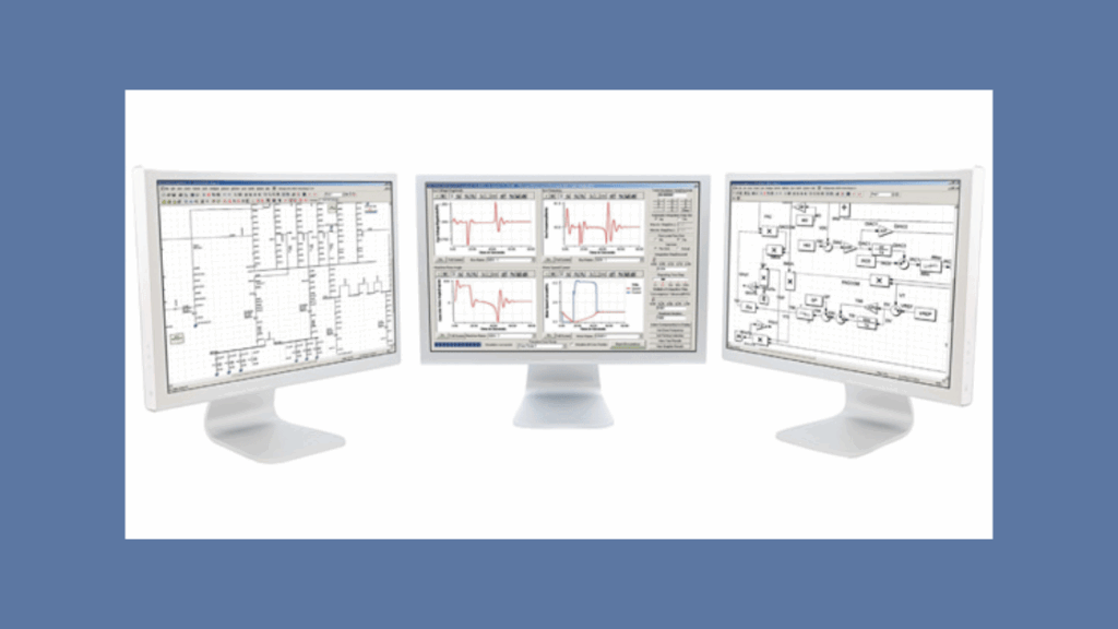
Load Flow Analysis and Studies in Electrical Power Systems

What Are Grounding System Studies?
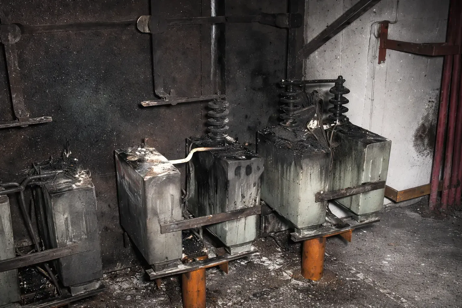
Grounding system studies analyze the electrical behavior of grounding networks during fault conditions.
Grounding studies evaluate:
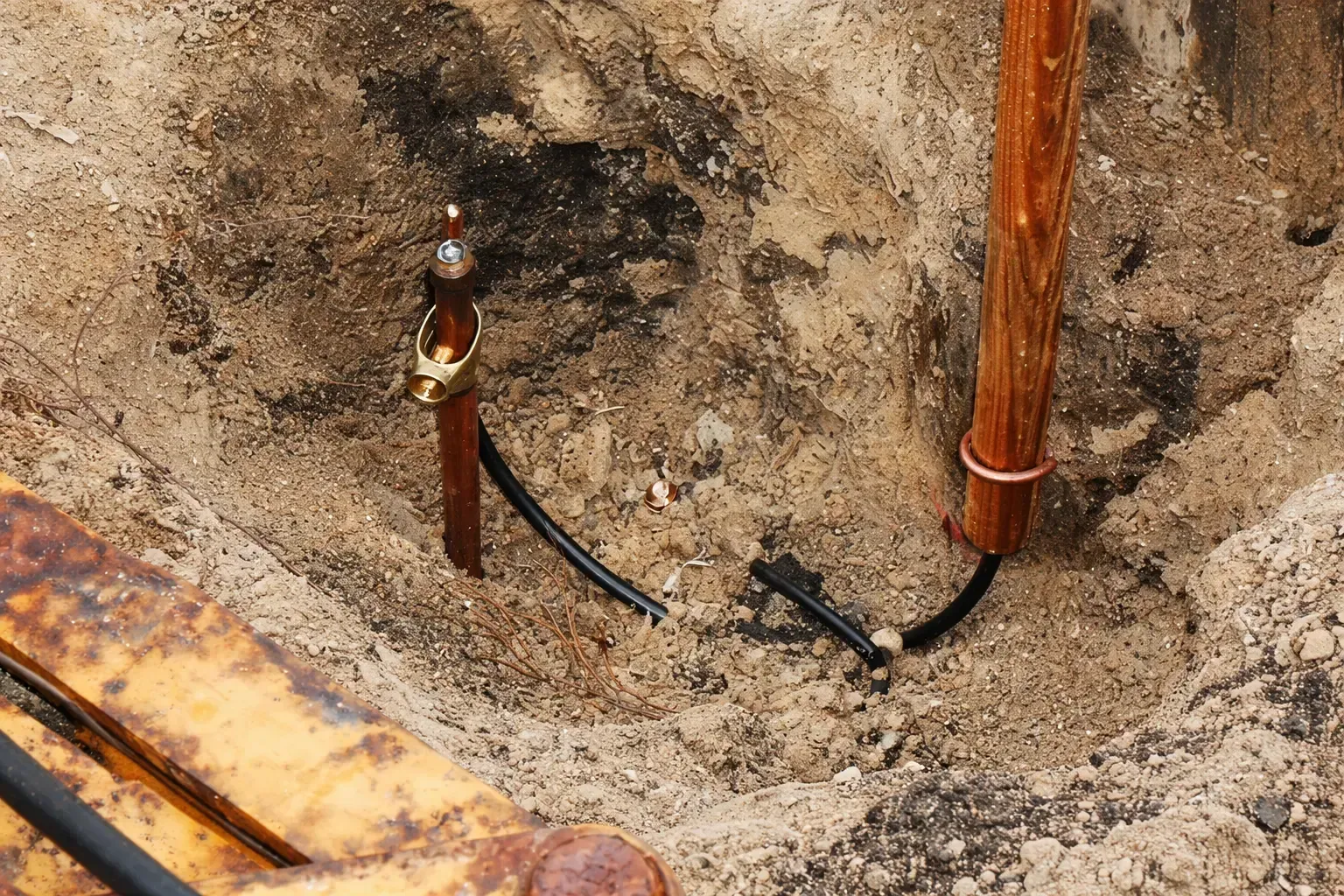
- Ground grid resistance
- Fault current dissipation
- Step voltage levels
- Touch voltage levels
- Ground potential rise (GPR)
Our Software Capabilities
 PSS®E
PSS®E
 ETAP
ETAP
 PSCAD
PSCAD
 PowerWorld
 SKM PTW
 AutoCAD Elec.
 ASPEN
ASPEN
General FAQs
What is PSS®E software?
PSS®E (Power System Simulator for Engineering) is a power system simulation software developed by Siemens for analyzing and planning electrical transmission networks. It allows engineers to model large-scale power systems and perform detailed studies related to grid reliability and system performance.
What is PSS®E used for in power system studies?
PSS®E is used for transmission planning, interconnection studies, contingency analysis, stability simulations, and grid expansion planning.
Who uses PSS®E software?
Electric utilities, transmission planners, system operators, renewable energy developers, consulting firms, and research institutions.
Can PSS®E be used for renewable energy integration?
Yes. PSS®E supports modeling of inverter‑based resources such as solar plants, wind farms, and battery storage.
Why is PSS®E widely used in transmission planning?
It supports very large power system models (up to 200,000 buses), advanced dynamic simulations, and automated workflows.
Technical FAQs
How does PSS®E perform contingency analysis?
Simulates outage scenarios (line/generator/transformer failures) and identifies voltage or thermal violations.
What dynamic simulations can be performed?
Transient stability, generator dynamics, renewable inverter response, and disturbance ride‑through.
What is PV / QV analysis?
Evaluates voltage stability margins and determines the system's ability to maintain voltage under increasing load.
How does PSS®E support large models?
Optimized numerical algorithms and sparse matrix techniques allow simulation of networks with up to 200,000 buses.
Can PSS®E simulations be automated?
Yes, via extensive Python APIs for contingency automation, batch simulations, and custom workflows.
General FAQs
What is ETAP software?
ETAP is an electrical power system engineering platform for design, simulation, analysis, and operation of industrial and utility networks.
What studies can ETAP perform?
Power flow, short circuit, arc flash, protection coordination, harmonic, and dynamic stability.
What industries use ETAP?
Utilities, renewable plants, data centers, oil & gas, industrial manufacturing, and infrastructure.
What is ETAP Electrical Digital Twin?
A virtual model that mirrors the physical network for predictive simulation and real‑time monitoring.
Why is ETAP widely used?
Integrated design, simulation, monitoring, and optimization in one platform.
Technical FAQs
How does ETAP perform short circuit analysis?
Uses ANSI/IEEE C37 and IEC 60909 standards to evaluate fault currents and equipment ratings.
What is ETAP arc flash analysis?
Calculates incident energy and safety boundaries per IEEE 1584 and NFPA 70E.
How does ETAP perform protection coordination?
Uses TCC curves to evaluate relay/breaker/fuse coordination for selective fault isolation.
Can ETAP simulate renewables?
Yes – solar PV, wind generators, battery storage, and microgrids.
What dynamic simulations are available?
Generator trips, faults, motor starting, switching events, and transient stability.
General FAQs
What is PSCAD?
Electromagnetic transient (EMT) simulation software for fast electrical phenomena in power systems.
What is PSCAD used for?
HVDC studies, converter modeling, inverter simulations, lightning surge analysis, and EMT studies.
Who uses PSCAD?
Utilities, renewable developers, manufacturers, consultants, and research institutions.
Why is PSCAD important for renewables?
Simulates inverter‑based resources and complex electromagnetic interactions.
What systems can PSCAD model?
Transmission networks, HVDC, renewable plants, power electronics, and protection systems.
Technical FAQs
What is EMT simulation?
High‑frequency analysis of switching, lightning, and converter transients.
How does PSCAD model transmission lines?
Distributed parameter models capture traveling wave behavior.
What time steps are used?
Microseconds to tens of microseconds, depending on system complexity.
Can PSCAD simulate HVDC?
Yes, detailed models for LCC and VSC HVDC systems.
How does PSCAD simulate inverters?
Uses detailed converter control models for grid‑forming/following behavior.
General FAQs
What is PowerWorld?
Power system visualization and simulation software for transmission networks.
What is PowerWorld Simulator?
Interactive tool for power flow, contingency analysis, and voltage stability.
Who uses PowerWorld?
Utilities, transmission planners, operators, consultants, universities.
What studies can be performed?
Power flow, contingency, OPF, voltage stability, fault analysis.
What makes PowerWorld unique?
Interactive animated one‑line diagrams and geographic displays.
Technical FAQs
How does contingency analysis work?
Simulates outage scenarios and flags overloads or voltage violations.
What numerical method is used?
Newton‑Raphson for efficient large‑system power flow.
What is PV/QV analysis?
Determines voltage stability margins and collapse points.
What is OPF?
Optimal Power Flow – minimizes cost while respecting constraints.
How large a system can it handle?
Up to approximately 250,000 buses.
General FAQs
What is SKM PowerTools?
Electrical engineering platform for power system design, analysis, and safety.
What studies can SKM perform?
Load flow, short circuit, arc flash, coordination, harmonics, grounding.
What industries use SKM?
Utilities, industrial plants, data centers, oil & gas, commercial buildings.
What is SKM CAPTOR?
Protective device coordination module using TCC curves.
Why is SKM widely used?
Integrated modules allow multiple studies in one platform.
Technical FAQs
How does SKM perform short circuit analysis?
Uses ANSI/IEC standards, calculates symmetrical/asymmetrical fault currents.
What is arc flash analysis in SKM?
Incident energy and boundaries per IEEE 1584 / NFPA 70E.
How does SKM perform load flow?
Calculates voltage levels, power flows, and system losses.
Can SKM simulate harmonics?
Yes, HI_WAVE module evaluates distortion from non‑linear loads.
How does SKM evaluate protection coordination?
Analyzes TCC curves to ensure selective fault isolation.
General FAQs
Difference between AutoCAD and AutoCAD Electrical?
AutoCAD Electrical provides intelligent automation: wire numbering, component tagging, error checking.
Suitable for substation design?
Yes – protection schematics, relay panels, AC/DC diagrams.
NERC compliance?
Supports traceable documentation, tagging, and QA/QC processes.
Relay protection design?
Create relay logic, trip/close circuits, CT/PT connections, custom vendor symbols.
How does it improve productivity?
Automated wire numbering, component tagging, report generation, error checking.
Technical FAQs
Automatic BOM generation?
Yes, extracts real‑time data for BOM, panel schedules, cable lists.
Useful for industrial control?
Widely used for PLC, MCC, SCADA, and factory automation.
Multi‑user collaboration?
Yes, shared project databases + Autodesk Vault integration.
Supports IEC / ANSI standards?
Built‑in symbol libraries for IEC, ANSI, JIC; switchable standards.
Which industries use it?
Power utilities, renewables, oil & gas, manufacturing, infrastructure.
General FAQs
What makes ASPEN OneLiner essential for protection engineers?
ASPEN OneLiner provides advanced short circuit analysis and relay coordination capabilities, enabling engineers to simulate faults, validate protection schemes, and ensure compliance with ANSI, IEC, and NERC standards.
How does ASPEN Power Flow support transmission planning?
It allows engineers to analyze voltage profiles, system losses, and contingency conditions, helping utilities plan system expansions and ensure operational reliability.
Why is phase-domain modeling important in DistriView?
Phase-domain modeling captures unbalanced conditions in distribution systems, providing more accurate results compared to traditional sequence-based methods.
How does the Breaker Rating Module ensure equipment safety?
It simulates worst-case faults, calculates adjusted currents using X/R ratios, and compares them against breaker ratings per ANSI/IEC standards.
What role does the Line Database play in system studies?
It provides highly accurate impedance and capacitance parameters, which are critical inputs for fault and load flow calculations.
Technical FAQs
How does Power Flow handle voltage control?
It uses automatic algorithms for generators, LTC transformers, shunts, and phase shifters.
What is the importance of X/R ratio in breaker studies?
It affects the asymmetrical current and determines the actual interrupting duty on breakers.
How does DistriView perform harmonic analysis?
It includes frequency scan and harmonic load flow capabilities to evaluate system distortion.
What is the advantage of ASPEN’s relay modeling?
It supports detailed manufacturer-specific relay logic, improving study accuracy.
How does ASPEN support renewable integration?
It models inverter-based resources such as solar, wind, and BESS systems.


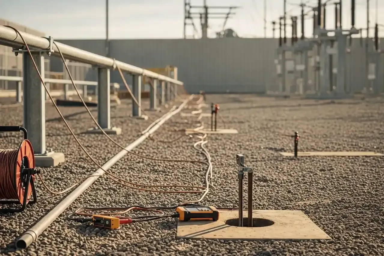
Grounding Study Methodology
Grounding system analysis follows a structured engineering approach to ensure electrical safety, system stability, and compliance with industry standards.
These studies are often performed alongside load flow analysis
01
GPR Analysis
Fault current behavior
02
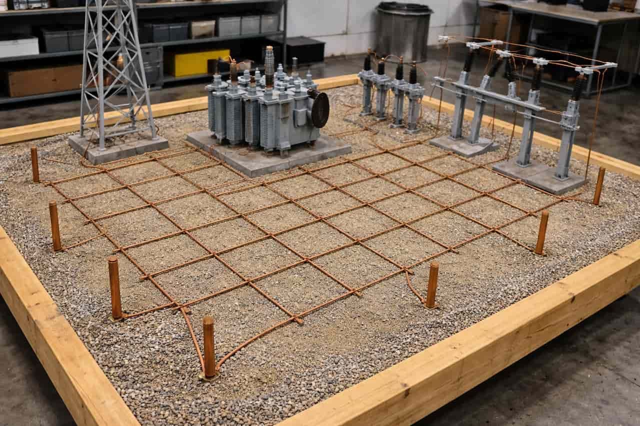
Ground Grid Modeling
System modeling
03
Soil Resistivity
Site measurement
04
Voltage Evaluation
Safety limits
Step 01
GPR Analysis
Ground Potential Rise occurs when fault current flows into the grounding system. This analysis evaluates maximum GPR levels and ensures personnel safety.
- Maximum GPR levels
- Equipment impact
- Safety evaluation
- Fault current behavior
Ensures safe operation during fault conditions.
Step 02
Ground Grid Modeling
Engineers develop a detailed model of the grounding system including conductors, rods, and equipment connections.
- Ground conductors
- Ground rods
- Structures
- Equipment grounding
- Grid layout
- System modeling
Provides accurate simulation of grounding network.

Step 03
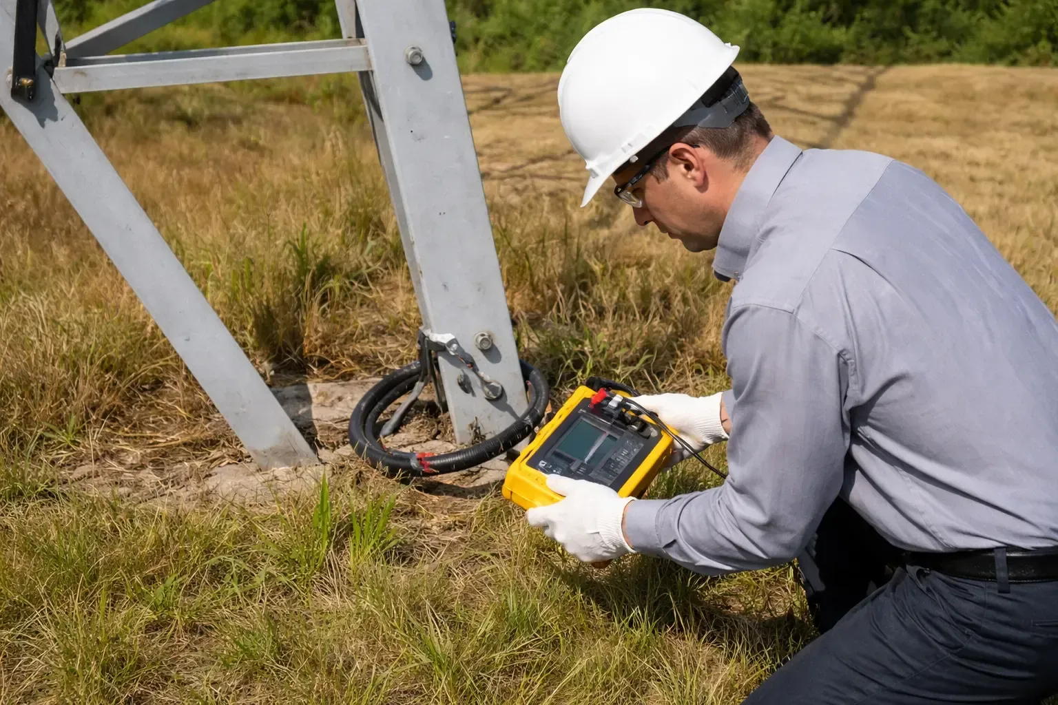
Soil Resistivity
Soil resistivity measurement determines how effectively fault currents dissipate into ground.
- Soil testing
- Site analysis
- Current dissipation
- Design input
Critical for proper grounding system design.
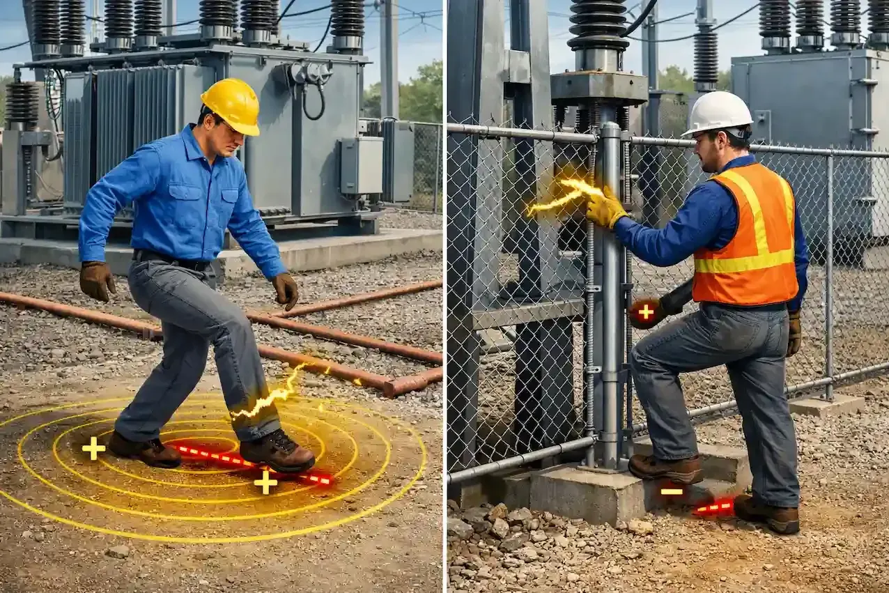
Step 04
Voltage Evaluation
Ensures that voltage levels experienced by personnel remain within safe limits during faults.
- Step voltage limits
- Touch voltage limits
- Safety checks
- Compliance verification
Ensures compliance with safety standards.
Types of Grounding Systems
Electrical power systems use different grounding configurations depending on system requirements.
Solid Grounding
Direct grounding of system neutral for fast fault clearing.
- High fault current
- Fast protection
- Low voltage systems
Resistance Grounding
Uses resistors to limit fault current and improve safety.
- Limits fault current
- Reduces damage
- Improves safety
Reactance Grounding
Uses reactance to control fault currents in high-voltage systems.
- High voltage systems
- Stable operation
- Controlled faults
Ungrounded Systems
No intentional grounding, allows continued operation during faults.
- Low fault current
- Continuous operation
- Needs monitoring
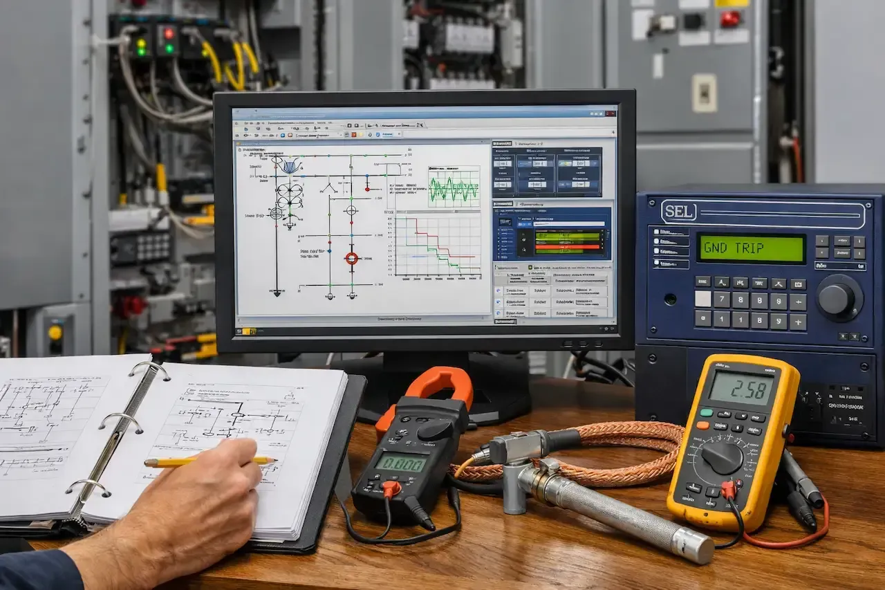
Software Tools Used for Grounding and Protection Studies
Our engineers use advanced simulation software to perform accurate fault analysis.
ETAP
Protection Analysis
DigSILENT
PowerFactory

DigSILENT
PowerFactory
PSS®E
Transmission

Who We've Served
Serving utilities, EPCs, developers, and infrastructure organizations supporting critical power systems nationwide.


Grid Code Compliance for Wind Farms: A Technical Overview for Electrical Engineers
The Importance of Electrical Power System Studies and Analysis
Substation Engineering Case Studies: Design, Protection & System Studies
Review of Large City & Metropolitan Area Power System Development Trends in 2025
Why Is Power System Analysis Important for BESS Owners?

Information Management for Inverter-Based Resources (IBRs): A Technical Guide
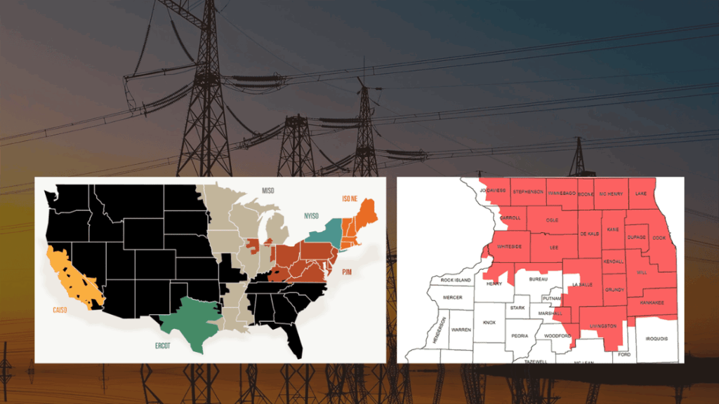
Transmission Engineering Solutions in the ComEd and PJM Territories

Power Trends 2025 — Navigating the Future of New York’s Electric Grid
Advancing Power System Design Practices with IEEE PES TR 126

Understanding Harmonic Studies in Offshore Wind Power Systems
Change Management Process in Power Systems: A Vital Link Between Operations and Planning
Comprehensive Power System Analysis – Industrial Reliability & Safety
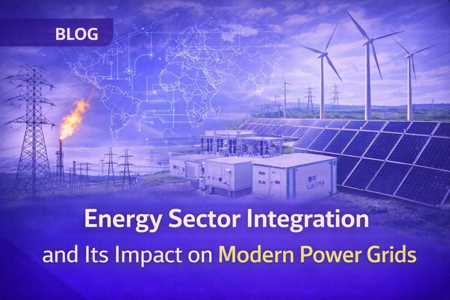
Energy Sector Integration and Its Impact on Modern Power Grids — Technical Perspective

Advanced Insights into Power System Modeling for Long-Term Resource Planning

Why Is Utility Interconnection Critical for Renewable Power Plants?

Keentel Engineering Power Pulse Newsletter – April 2025 Edition
How Can Synchrophasor Technology Be Utilized for Monitoring and Controlling Power System Stability?
How Can Renewable Power Plants Prevent Electrical Grid Failures?

Ensuring Design Stability in Power System Projects — Best Practices & NERC Deadlines
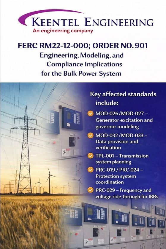
FERC RM22-12-000; Order No. 901 Explained — Engineering & Compliance Implications


