A Coordinated Electric System Interconnection Review—the utility’s deep-dive on technical and cost impacts of your project.
Challenge: Frequent false tripping using conventional electromechanical relays
Solution: SEL-487E integration with multi-terminal differential protection and dynamic inrush restraint
Result: 90% reduction in false trips, saving over $250,000 in downtime
The three operating regions you have to design to
| Device | Output vs voltage | Response | Best suited to | Main limitations |
|---|---|---|---|---|
| Mechanically switched capacitor or reactor | Proportional to voltage squared | Seconds; discrete steps; limited switching operations per day | Steady-state reactive supply, voltage profile, loss reduction | No dynamic capability; step voltage change on switching; capability collapses when most needed |
| Static var compensator | Capacitive branches proportional to voltage squared | A few cycles; continuously controllable | Continuous control where cost matters and deep voltage support is not the driver | Square-law capability loss; harmonic filters are part of the plant and interact with the network |
| STATCOM | Approximately proportional to voltage — constant current capability | One to two cycles closed loop; converter response faster still | Voltage stability margin, weak interconnections, fast disturbance recovery, flicker and unbalance compensation | Higher capital cost; converter losses; adds a converter and its control dynamics to the network |
| Synchronous condenser | Governed by machine capability and excitation | Excitation response in the hundreds of milliseconds; inherent inertial response instantaneous | System strength and inertia, short-circuit contribution, black start support | Rotating plant with maintenance and losses; slower controlled response than a converter |
| STATCOM with energy storage | Reactive as a STATCOM, plus real power within the storage rating | As STATCOM for reactive; real power limited by storage | Where a real power deficiency is part of the problem | Cost and complexity of the storage; different failure and maintenance profile |
| Stage | Keentel scope | Outcome |
|---|---|---|
| Screening | Series-compensation proximity, radial contingency review, UIF and short-circuit ratio screening, frequency scans | Early identification of which SSO types apply |
| Detailed studies | PSCAD/EMTDC EMT studies with vendor real-code models, impedance-based and frequency-scan analysis | Clear evidence of stability margins or risk |
| Model quality | EMT model review, benchmarking against positive-sequence models, model acceptance support | Models that system operators accept |
| Mitigation | Control retuning recommendations with vendors, SSDC and bypass logic requirements, protection and monitoring specifications | Practical, coordinated solutions |
| Interconnection support | SSR and SSO study reports for ISO and utility requirements, response to reviewer comments | Fewer delays in the interconnection process |
Resilience: designing CDUs to the facility Tier objective
Liquid cooling makes heat removal more critical, not less. Cold plates hold only seconds of thermal buffer. If TCS flow stops, processors throttle or shut down very quickly. Resilience design must therefore cover:
- Pump redundancy: N+1 pumps at minimum, with automatic changeover.
- CDU redundancy: N+1 CDUs on a common TCS header, or 2N CDUs serving A and B manifolds for fault-tolerant designs.
- Power to CDUs: dual-corded CDUs fed from A and B sources, with pumps and controls on UPS power so coolant keeps flowing through a utility failure and generator start. This is the liquid-cooling equivalent of continuous cooling.
- Facility water continuity: chilled water or condenser water must also continue, through thermal storage, UPS-backed pumps or a high enough FWS temperature that the TCS can coast on stored thermal mass for the transfer period.
- Concurrent maintainability: isolation valves so any CDU, pump, filter or manifold section can be serviced without stopping the others.
- Leak management: leak detection, drip trays, automatic isolation valves and procedures for fluid spills.
Electrical engineering considerations
CDUs and liquid-cooling plants are electrical loads with their own design requirements:
- Pump motors and VFDs. Large CDUs use variable-frequency drives on their pump motors. These introduce harmonic current that must be included in the facility's harmonic study and IEEE 519 evaluation.
- Critical mechanical load on UPS. Putting CDU pumps on UPS increases UPS and battery sizing. The mechanical UPS load must be included in redundancy and ride-through calculations.
- Feeder and protection design. Dual feeds, automatic transfer, selective coordination and arc-flash labelling apply to CDU power distribution just as they do to IT power.
- Generator transient response. CDU pumps restarting together after a transfer create motor inrush on the generators. Staged restarts and soft acceleration reduce the step load.
- Load dynamics. AI training loads can swing rapidly between high and low power. Cooling controls must track those swings without temperature overshoot, and electrical systems must handle both the IT and the cooling load changes.
Commissioning a liquid-cooled data hall
- Flush and clean the TCS piping and manifolds to the specified cleanliness, using high-purity flush water.
- Fill and vent with the specified coolant, verifying glycol concentration and chemistry.
- Pressure test for leaks at design and test pressures, including quick-disconnect fittings.
- Verify sensors and controls: flow meters, temperature sensors, pressure transmitters, leak detection and BMS points.
- Load test with heat load banks connected through the cold-plate interfaces or rack manifolds, across the operating range.
- Prove the heat balance on both loops at several load steps, and the approach temperature against the design.
- Test failure scenarios: pump failure, CDU failure, power transfer to generator, valve failure and loss of facility water, confirming temperatures stay within the IT vendor's limits.
How Keentel Engineering helps
Keentel Engineering supports data center owners, developers and EPCs with the electrical engineering that liquid-cooled facilities depend on, and coordinates with the mechanical engineer of record and cooling vendors on the integrated design.
Grounding System Testing: IEEE 80 & IEEE 81 Engineering Guide
October 20, 2026 | Blog
Part A — Grounding System Testing at a Glance
A grounding system is invisible once it is buried. Copper conductors, ground rods and connections lie under crushed rock, concrete and soil, and they stay there for forty years or more. Yet every time a fault occurs at a substation, a solar plant, a battery facility or a data center, that buried system decides whether people standing nearby are safe, whether protective relays operate correctly and whether equipment survives. Grounding testing is how engineers prove — before energization and throughout the life of the facility — that the system in the ground matches the system in the design.
In US practice, the term is grounding rather than earthing, and the governing references are IEEE Std 80 (safety in AC substation grounding), IEEE Std 81 (measuring soil resistivity, ground impedance and earth surface potentials), IEEE Std 142 (grounding of industrial and commercial power systems), IEEE Std 367 (ground potential rise), the National Electrical Safety Code (NESC, ANSI C2) for utility facilities, and NFPA 70 (National Electrical Code) for premises wiring. Acceptance testing typically follows ANSI/NETA ATS, and maintenance testing follows ANSI/NETA MTS.
The seven core grounding tests
| Test | What it measures | Typical US method | Primary purpose |
|---|---|---|---|
| 1. Ground resistance | Resistance of an electrode, rod bed or grid to remote earth | Fall-of-potential (three-point), clamp-on for multi-grounded systems | Confirm design resistance and calibrate GPR calculations |
| 2. Ground grid impedance | Impedance of a large grid at power frequency | Fall-of-potential with long leads, frequency-selective or high-current injection | Determine ground potential rise for large substations |
| 3. Grounding continuity (bonding) | Resistance between equipment and the grid, and between grid points | Two-point low-resistance (micro-ohmmeter) test | Find broken, corroded or missing connections |
| 4. Soil resistivity | Apparent resistivity of soil at various depths | Wenner four-pin or Schlumberger method | Provide the soil model for grounding design |
| 5. Step voltage | Voltage between two points 1 m apart on the ground surface | Current injection with surface potential measurement, scaled to fault current | Verify protection of people walking near equipment |
| 6. Touch voltage | Voltage between a grounded metal object and the ground 1 m away | Current injection with surface potential measurement, scaled to fault current | Verify protection of people touching equipment |
| 7. Protective conductor verification | Size, continuity, routing and termination of equipment grounding conductors | Inspection, NEC Article 250 and design review, continuity tests | Ensure fault current returns safely and protective devices operate |
Key engineering points
- Resistance is not safety. A low grid resistance is useful, but people are protected by limiting touch and step voltages, which depend on grid geometry, surface material and fault clearing time as much as on resistance.
- Measured voltages must be scaled. A touch or step measurement made with a few amperes of test current must be scaled to the actual ground fault current returning through the grid before it can be compared with tolerable limits.
- Test layout determines accuracy. For large grids, test leads must extend several times the grid diagonal, and mutual coupling between leads must be controlled.
- Testing is a lifecycle activity. Soil resistivity is measured before design, resistance and continuity at commissioning, and continuity and resistance again after additions, after faults and on a maintenance schedule.
Good grounding equals safe people, protected equipment and a reliable power system. The only way to know you have it is to test it — correctly.
Part B — Grounding System Testing: An Engineering Guide for US Substations, Transmission Lines, Solar and BESS Plants, and Data Centers
1. Why grounding testing matters
Ground faults are the most common fault type on US power systems. When a single-line-to-ground fault occurs at or near a substation, part of the fault current returns to its source through the earth. As that current flows into the soil from the substation grid, the grid rises in potential relative to remote earth. This ground potential rise (GPR) can reach thousands of volts at a transmission substation. Voltage gradients form on the soil surface around the grid, and anyone standing on the ground while touching grounded equipment, or walking across the surface, can be exposed to a hazardous voltage difference.
A properly designed grounding system:
- Protects people by limiting touch, step and transferred voltages to tolerable values for the expected fault clearing time.
- Protects equipment by providing a low-impedance path for fault and surge currents and limiting voltage differences between equipment.
- Supports protection by providing reliable fault current return so ground relays, fuses and breakers operate as intended.
- Controls overvoltages by establishing a system ground reference and supporting surge arrester performance.
- Reduces interference with control, communication and instrumentation circuits.
Testing verifies each of these functions. Without testing, a grounding design is only a calculation; with testing, it becomes a verified safety system.
1.1 Where testing is required in US practice
| Facility | Typical testing drivers |
|---|---|
| Utility substations (69 kV to 765 kV) | IEEE 80 design verification, NESC requirements, utility standards, NERC PRC-005 maintenance programs for protection system components that rely on grounding |
| Transmission lines | Structure footing resistance for lightning performance, shield wire continuity, NESC grounding requirements |
| Utility-scale solar and BESS plants | Collector system and substation grid design to IEEE 80, NEC Articles 250, 690, 691 and 706, interconnection requirements, owner and lender commissioning specifications |
| Wind farms | Turbine foundation grounding, collector system grounding, lightning protection |
| Data centers and industrial facilities | NEC Article 250, IEEE 142 and IEEE 1100 (powering and grounding electronic equipment), NFPA 780 lightning protection, ANSI/NETA ATS acceptance testing |
| Telecommunication sites and control buildings | Bonding networks and low-impedance grounding for electronic equipment |
2. Fundamentals: GPR, touch and step voltage
2.1 Ground potential rise
The ground potential rise of a grid is the product of the current flowing from the grid into the earth and the grid's impedance to remote earth:
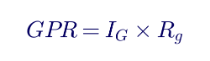
where IG is the maximum grid current and Rg is the grid resistance (or impedance). IG is not the total fault current. Much of the fault current returns through overhead shield wires, cable sheaths, neutral conductors and other metallic paths. The fraction that actually flows into the earth from the grid is the current split factor Sf:
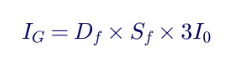
where 3I0 is the symmetrical ground fault current and Df is the decrement factor accounting for DC offset over the fault duration.
2.2 Touch voltage
Touch voltage is the potential difference between a grounded metallic structure a person is touching and the ground surface where the person is standing, normally taken at a horizontal distance of 1 m (about 3.3 ft). The worst touch voltage inside a grid typically occurs at the center of a mesh — the mesh voltage Em.
2.3 Step voltage
Step voltage is the potential difference between two points on the ground surface 1 m apart, which a person could bridge with their feet without touching any grounded object.
2.4 Transferred voltage
Transferred voltage occurs when a conductor connected to the grid — a fence, a rail, a pipe, a cable shield or a communication circuit — extends outside the grid area. A person touching that conductor remote from the substation can be exposed to nearly the full GPR. Transferred voltages are often the most dangerous and the most overlooked.
2.5 Tolerable limits under IEEE 80
IEEE 80 bases tolerable voltage on the current a human body can withstand without ventricular fibrillation, which depends on body weight and shock duration. For a 50 kg person, the tolerable touch and step voltages are:
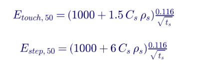
For a 70 kg person, the constant 0.116 becomes 0.157. In these equations, ts is the shock duration in seconds (normally the fault clearing time), ρs is the resistivity of the surface material in Ω·m and Cs is the surface layer derating factor:
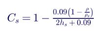
where ρ is the native soil resistivity and hs is the surface layer thickness in meters.
The 1,000 Ω term is the assumed body resistance. The surface layer, typically crushed rock, adds resistance in series with the feet, which is why a layer of clean, high-resistivity crushed rock dramatically raises the tolerable voltages.
| Region | Land-position pattern | Engineering question Keentel tests |
|---|---|---|
| PJM | Largest hyperscaler land holdings; dense AI-ready designs in Northern Virginia and new clusters in rural Virginia, Ohio and Illinois | Can 500 kV / 230 kV backbone and load-serving substations absorb multi-GW additions on the developer's schedule? |
| West (non-RTO) | Large hyperscaler positions in the Pacific Northwest, Nevada and Arizona | Which utility planning process applies, and what transmission upgrades does a new campus trigger? |
| MISO | Emerging market; large tracts in Iowa, Illinois, Louisiana and beyond, far from population centers | Is there a nearby EHV source, and how do large-load studies interact with the generator queue? |
| ERCOT | Strong co-location and "powered land" activity | How do large-load interconnection and ride-through requirements shape the design? |
| SPP and Southeast | Strategic positions by co-location developers avoiding direct hyperscaler competition | What is the realistic substation and line build needed to serve the site? |
| CAISO, NYISO, ISO-NE | Mature, near saturation; limited new land | Can existing sites be upgraded or densified? |
Crushed rock more than triples the tolerable touch voltage in this example. But crushed rock must remain clean and well-drained: rock contaminated with soil or fines loses much of its resistivity, and wet rock can have far lower resistivity than dry samples. Many utilities measure the resistivity of the rock source used on site.
2.6 Why clearing time matters
Tolerable voltage varies inversely with the square root of shock duration. Halving the clearing time from 0.5 s to 0.25 s raises the tolerable limits by about 41%. Primary relaying clearing time is often used for design, but many utilities use backup clearing time conservatively, because a person could be exposed during the slower backup operation. The choice must be documented and consistent with the protection scheme.
3. Soil resistivity testing
Soil resistivity is the single most important input to grounding design. Native soil resistivity in the US varies from below 10 Ω·m in wet clay and coastal soils to several thousand Ω·m in rock, sand and desert soils. It also varies with depth, moisture, temperature and season, so layered soil models are normally required.
3.1 The Wenner four-pin method
Four probes are driven in a straight line at equal spacing a. Current is injected between the outer probes (C1 and C2) and voltage is measured between the inner probes (P1 and P2). When probe depth is small compared to spacing, the apparent resistivity is:
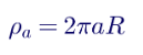
where a is the probe spacing in meters and R is the measured resistance V/I in ohms. Measurements at increasing spacings sample deeper soil, roughly to a depth comparable to the spacing.
3.2 Worked example: Wenner survey for a 138 kV substation
| Spacing a (ft) | Spacing a (m) | Measured R (Ω) | Apparent resistivity ρa (Ω·m) |
|---|---|---|---|
| 5 | 1.52 | 12.7 | 122 |
| 10 | 3.05 | 5.6 | 107 |
| 20 | 6.10 | 2.5 | 96 |
| 40 | 12.19 | 1.1 | 84 |
| 80 | 24.38 | 0.62 | 95 |
The data indicate a slightly more resistive upper layer of roughly 120 Ω·m over soil of about 85 to 95 Ω·m. For the design example that follows, a uniform resistivity of 100 Ω·m is used as a representative value; in practice, software such as SES CDEGS, ETAP or WinIGS fits a two-layer or multilayer model to the curve.
3.3 Good practice for resistivity surveys
- Survey multiple traverses across the site, normally in at least two perpendicular directions, to detect lateral variation.
- Extend spacing far enough — commonly up to the largest dimension of the planned grid — to characterize the deeper soil that controls grid resistance.
- Avoid buried metal such as pipelines, fences and existing grids, which distort readings.
- Record conditions: moisture, temperature, recent rain and frozen ground affect results.
- Check data quality: repeat questionable points and look for readings that change unreasonably between spacings.
- Use the Schlumberger method when very large spacings are needed with less probe movement.
4. Ground resistance testing
4.1 The fall-of-potential method
The fall-of-potential method in IEEE 81 is the reference method for measuring the resistance of an electrode or grid to remote earth. Current is injected between the electrode under test (E) and a remote current probe (C). A potential probe (P) is placed at various positions along the line between them, and the apparent resistance R = V/I is plotted against probe position.
- If the current probe is far enough away, the curve flattens in the middle; the flat portion represents the true resistance.
- For a hemispherical electrode in uniform soil, the true resistance is measured with the potential probe at 61.8% of the distance to the current probe. This is known as the 61.8% rule.
- For large grids, the "flat" region may not exist unless the current probe is very far away, and the 61.8% rule is only an approximation.
4.2 Worked example: fall-of-potential on a large grid
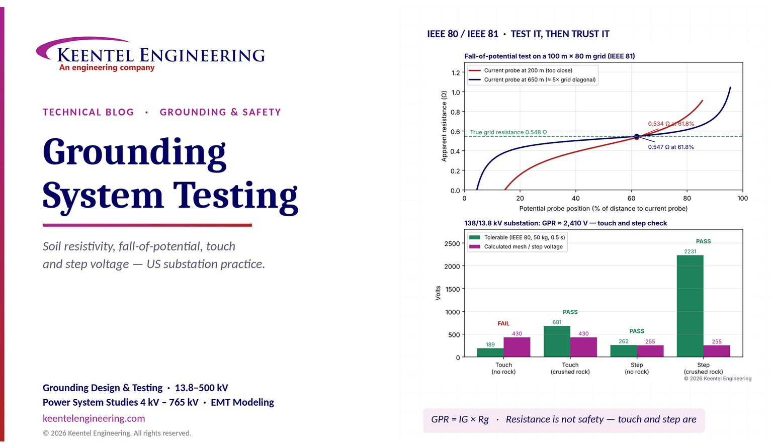
Keentel modeled a fall-of-potential test on a 100 m × 80 m substation grid with a true resistance of 0.548 Ω in 100 Ω·m soil. The grid diagonal is about 128 m.
| Current probe distance | Shape of curve | Reading at 61.8% |
|---|---|---|
| 200 m (about 1.6 × diagonal) | No flat region; resistance changes continuously | 0.534 Ω |
| 650 m (about 5 × diagonal) | Broad flat region from about 40% to 70% | 0.547 Ω |
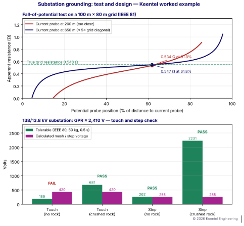
Figure 1. Top: simulated fall-of-potential curves for the same grid with two current probe distances. Bottom: touch and step voltage check for the 138/13.8 kV design example in Section 6.
In uniform soil, the 61.8% reading is still close to the true value even at 200 m, but the absence of a flat region means the engineer cannot verify the result from the data. In layered or non-uniform soil, readings with a close current probe can be badly in error. IEEE 81 guidance is to place the current probe at a distance of several times the largest grid dimension, commonly 3 to 5 times or more for large grids, and to confirm that a plateau exists.
4.3 Practical difficulties for large grids
- Long leads: for a large transmission substation, current probe distances of 600 m to 1,500 m or more may be needed, crossing roads, fences and property lines.
- Mutual coupling: current and potential leads run in parallel induce voltage in each other at power frequency, causing errors. Leads should be separated or run at an angle, and test frequencies away from 60 Hz help.
- Stray currents and noise: energized substations carry 60 Hz ground currents and harmonics. Frequency-selective instruments inject at frequencies such as 97 Hz or 128 Hz and filter out power-frequency noise.
- Metallic connections: shield wires, neutrals and cable sheaths connected to the grid make the measured value represent the whole interconnected system, not the grid alone. Some tests intentionally include these paths; others require them to be disconnected.
4.4 Clamp-on (stakeless) measurement
Clamp-on testers induce a voltage in a loop and measure the resulting current. They are fast and convenient for multi-grounded distribution poles, telecom sites and structures with a parallel ground path, but they require a loop. They do not measure an isolated electrode, and they cannot measure a substation grid connected to many parallel paths in a meaningful way.
4.5 Typical design targets
These values are targets, not proof of safety. IEEE 80 requires that touch and step voltages be within tolerable limits, regardless of resistance.
5. Ground grid impedance and high-current testing
For very large grids connected to many shield wires and cable sheaths, the relevant quantity at power frequency is impedance rather than resistance, because inductive paths carry part of the current. Ground grid impedance testing methods include:
- Fall-of-potential with very long leads, using frequency-selective instruments.
- High-current injection: injecting tens to hundreds of amperes, often from an isolated source or a remote substation through a de-energized transmission line, and measuring GPR and surface voltages directly.
- Current-split measurements: measuring the current flowing in shield wires and neutrals during a test to determine the split factor experimentally.
The measured impedance is used to calculate GPR for the design fault current:

6. Worked example: 138/13.8 kV distribution substation grid
6.1 Design data
| Parameter | Value |
|---|---|
| Substation | 138/13.8 kV distribution substation |
| Grid area | 100 m × 80 m (about 328 ft × 262 ft) |
| Conductor | 4/0 AWG bare copper, buried 0.5 m (about 20 in) |
| Mesh spacing | 10 m in both directions (9 conductors × 100 m, 11 conductors × 80 m) |
| Ground rods | Twenty 3 m (10 ft) rods around the perimeter |
| Soil resistivity | 100 Ω·m (from Section 3) |
| Surface layer | 0.1 m (4 in) clean crushed rock, 3,000 Ω·m |
| Maximum 138 kV single-line-to-ground fault | 10 kA |
| Current split factor | 0.40 (60% returns through shield wires and other paths) |
| Decrement factor | 1.10 |
| Shock duration | 0.5 s |
6.2 Step 1: conductor sizing
IEEE 80 gives the minimum conductor size for a given fault current and duration. For soft-drawn copper with a fusing temperature of 1,083°C and ambient of 40°C, the simplified form is:

With I = 11 kA (including decrement), Kf = 7.00 and tc = 0.5 s, the minimum size is about 54 kcmil. Many US utilities use 4/0 AWG (211.6 kcmil) or larger for mechanical strength, corrosion allowance and future fault growth, and limit the conductor temperature to a lower value, such as 250°C for compression and mechanical connections.
6.3 Step 2: grid resistance
The Sverak equation in IEEE 80 estimates grid resistance including the effect of depth:

With LT = 1,780 m of grid conductor plus 60 m of rods (1,840 m total) and A = 8,000 m², Rg = 0.548 Ω.
6.4 Step 3: maximum grid current and GPR
I
G = 1.10 × 0.40 × 10,000 = 4,400 A, and GPR = 4,400 × 0.548 ≈ 2,410 V.
Since the GPR exceeds the tolerable touch voltage, detailed mesh and step voltage calculations are required.
6.5 Step 4: mesh (touch) voltage
IEEE 80 gives the mesh voltage as:
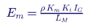
where Km is the spacing factor, Ki is the irregularity factor and LM is the effective buried length. For this grid, the effective number of parallel conductors n is about 9.9, Km ≈ 0.867, Ki ≈ 2.11 and LM ≈ 1,875 m. The mesh voltage is about 430 V.
6.6 Step 5: step voltage
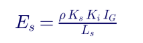
With Ks ≈ 0.380 and Ls ≈ 1,386 m, the step voltage is about 255 V.\
6.7 Step 6: comparison
| Check | Calculated | Tolerable without rock | Tolerable with crushed rock | Result |
|---|---|---|---|---|
| Touch (mesh) voltage | 430 V | 189 V | 681 V | Passes only with crushed rock |
| Step voltage | 255 V | 262 V | 2,231 V | Passes; marginal without rock |
The design is safe because of the crushed rock surface layer. If the rock were contaminated or omitted in part of the yard, the touch voltage criterion would fail. That is a strong argument for verifying surface material during commissioning and maintenance — and for considering additional measures at locations where rock cannot be maintained, such as gates, fence corners and areas outside the yard.
6.8 Step 7: the fence
The perimeter fence requires special attention. Touch voltage outside the fence, where there may be no crushed rock, can be the governing hazard. Common US practices include extending crushed rock outside the fence, bonding the fence to the grid with a perimeter conductor outside the fence line, or isolating the fence from the grid. The chosen approach must be analyzed, because each changes the outside-the-fence touch voltage.
7. Step and touch voltage testing
7.1 Test method
Direct measurement of touch and step voltages follows the method in IEEE 81:
- Inject a known test current, typically tens to hundreds of amperes for accurate surface measurements, between the grid and a remote current electrode.
- Measure the voltage between equipment and a test plate or probe on the surface 1 m away (touch), or between two plates 1 m apart (step).
- Use a load resistance representing the human body (commonly 1,000 Ω) across the measurement where the standard method specifies it, with weighted plates simulating feet.
- Scale the measured voltages to the design fault current.
7.2 Scaling measured values

For example, a touch voltage of 18 V measured with a 200 A test current represents a touch voltage of 18 × 4,400/200 = 396 V at the design grid current of 4,400 A. A single measured voltage without the test current, test frequency and scaling basis has no engineering meaning. The 18 V and 32 V values often seen on instrument displays are only useful when the test current and the design current are both stated.
7.3 Where to measure
| Location | Why it matters |
|---|---|
| Mesh centers in high-current areas | Highest touch voltage inside the grid |
| Equipment handles and operating mechanisms | Where people actually touch equipment |
| Perimeter fence, inside and outside | Outside-the-fence touch voltage often governs |
| Gates in open position | Gate swing may extend beyond rock and grid |
| Corners of the grid | Highest step voltages occur near grid edges |
| Points of transferred voltage | Rails, pipes, fences and communication cables leaving the site |
8. Grounding continuity and bonding tests
8.1 Two-point (point-to-point) testing
Continuity tests confirm that equipment is reliably connected to the grid and that the grid itself is intact. A low-resistance ohmmeter (micro-ohmmeter or ground bond tester) injects a DC or low-frequency current, typically 1 A to 10 A or more, between a reference point and the equipment ground connection.
| Test | Typical acceptance basis |
|---|---|
| Point-to-point resistance between the main grid and major equipment | ANSI/NETA ATS recommends investigating values exceeding 0.5 Ω |
| Comparison between similar connections | Values much higher than similar connections indicate a problem |
| Connection joints (exothermic and compression) | Very low milliohm values; consistent results across similar joints |
Practical tips:
- Use a known reference, such as a transformer neutral ground or a main grid riser, and measure all equipment back to it.
- Use four-wire (Kelvin) measurement to eliminate lead resistance.
- Look for trends, not just pass/fail: a connection that has doubled since the last test may be corroding.
- Test after modifications, because new construction often damages existing grid conductors.
8.2 Common defects found
- Grid conductors cut by excavation, fence post installation or conduit trenching.
- Corroded compression connections, especially in coastal and high-chloride soils.
- Missing jumpers across flexible joints, expansion fittings and gate hinges.
- Equipment grounded only through mounting bolts or painted surfaces.
- Theft of copper conductors at remote sites.
9. Protective conductor verification
In premises and plant wiring, the equipment grounding conductor (EGC) provides the low-impedance fault return path that allows overcurrent devices to operate. NEC Article 250 governs grounding and bonding for systems under 1,000 V and many medium-voltage applications. Verification includes:
- Size: the EGC meets NEC Table 250.122 based on the rating of the overcurrent device, increased proportionally where phase conductors are upsized for voltage drop.
- Continuity: a continuous path from each enclosure to the system bonding jumper and grounding electrode system.
- Installation: correct terminations, listed lugs, torque values, bonding jumpers across raceway fittings and no reliance on unlisted paths.
- Design compliance: routing and conductor type as specified, including any isolated ground circuits for sensitive electronic equipment.
- Effective ground-fault current path: NEC 250.4 requires a path capable of safely carrying the maximum fault current and facilitating overcurrent device operation.
9.1 Worked example: fault return impedance at 480 V
A 480Y/277 V feeder supplies a 400 A panel 250 ft from the switchboard, protected by a 400 A breaker. If a phase-to-enclosure fault occurs at the panel, the fault current must be high enough to trip the breaker's instantaneous element. Suppose the instantaneous pickup is set at 10 × 400 A = 4,000 A. The maximum allowable fault loop impedance is roughly:

If the phase conductors and EGC together, plus the source impedance, exceed this value, the breaker will not trip instantaneously and the fault may persist on its longer time-delay characteristic, raising touch voltage on the enclosure and arc-flash energy. Loop impedance testing or calculation confirms that the EGC and phase conductors are adequate.
10. Grounding for solar, BESS and wind plants
Renewable and storage plants present special grounding challenges:
- Large areas: solar plants cover hundreds or thousands of acres. The substation grid is designed to IEEE 80, while the array grounding is designed for equipment bonding, lightning protection and NEC compliance.
- Collector system grounding: 34.5 kV collector systems are commonly grounded through the main power transformer winding or a grounding transformer. Effective grounding affects overvoltage during ground faults.
- Inverter fault current: inverters contribute limited fault current, so the substation grid must be designed for the grid-side fault contribution.
- Battery enclosures: BESS containers require bonding, lightning protection and coordination with NFPA 855 and NEC Article 706.
- High-resistivity soils: many Southwest solar sites have sandy or rocky soils with resistivity of 1,000 Ω·m or more, requiring larger grids, deeper rods or enhanced backfill.
- Corrosion: steel piles and copper conductors in the same soil can create galvanic corrosion, which must be addressed in material selection.
11. Transmission line grounding
For transmission lines, footing resistance mainly affects lightning performance. When lightning strikes a shield wire or tower, the current flows to ground through the tower footing. High footing resistance raises the tower potential and can cause backflashover across insulators. Typical practices:
- Measure footing resistance at each structure, often with clamp-on or fall-of-potential methods with shield wires temporarily isolated where needed.
- Improve high-resistance footings with counterpoise (buried horizontal conductors), additional rods or ground enhancement material.
- Verify shield wire continuity and bonding.
At the substation, shield wires carry part of the fault current away from the grid, lowering GPR. This split must be modeled correctly, and shield wire connections must be maintained.
12. Data center grounding
Data centers combine utility-scale electrical infrastructure (often 69 kV to 345 kV substations) with dense electronic equipment requiring low-noise bonding. Key elements include:
- Substation grid designed to IEEE 80 where the campus owns its high-voltage substation.
- Grounding electrode system per NEC Article 250 for each building service.
- Mesh bonding networks within data halls per IEEE 1100 and TIA-607 telecommunications bonding standards.
- Lightning protection per NFPA 780.
- Generator and UPS grounding coordinated with the system grounding scheme to avoid circulating neutral currents and nuisance ground-fault trips.
Testing at data centers typically includes soil resistivity, electrode system resistance, point-to-point bonding resistance across the bonding network and verification of separately derived system grounding.
13. Instrumentation and test equipment
| Instrument | Use | Notes |
|---|---|---|
| Four-pole ground resistance tester | Soil resistivity and fall-of-potential | Frequency-selective models reduce noise in energized substations |
| Clamp-on ground tester | Multi-grounded systems and structures with a loop | Not for isolated electrodes or large grids |
| High-current injection set | Grid impedance, touch and step testing | Provides accurate surface voltage measurement |
| Low-resistance ohmmeter (micro-ohmmeter) | Continuity and bonding | Four-wire measurement; 10 A or more for reliable joint testing |
| Loop impedance tester | Premises fault loop impedance | Confirms overcurrent device operation |
| GPS and surveying tools | Probe locations and lead routing | Critical for repeatable tests |
All instruments should be calibrated, and test records should include instrument serial numbers, calibration dates, probe locations, weather and soil conditions.
14. Safety during testing
Grounding tests are performed at energized substations, where the grid itself may rise in potential during a system fault while test leads extend far outside the station. Safety measures include:
- Treat test leads as potentially energized: a system fault during testing can raise the grid, and therefore the leads, to the full GPR.
- Use insulated gloves and mats when connecting leads, and avoid testing during storms.
- Coordinate with system operations, including notification and, where required, switching.
- Barricade remote probes and lead routes crossing public areas.
- Follow OSHA 29 CFR 1910.269 and NFPA 70E requirements for work near energized equipment.
15. Lifecycle testing program
| Stage | Tests | Purpose |
|---|---|---|
| Site selection and design | Soil resistivity survey | Build the soil model |
| Construction | Inspection of conductors, connections and rods before backfill; photographs | Verify installation before it is buried |
| Commissioning | Grid resistance or impedance, point-to-point continuity, touch and step (for critical sites), surface layer resistivity | Confirm design performance |
| After additions or modifications | Continuity of new connections and existing grid; updated resistance and GPR analysis | Verify the system remains safe |
| After major faults | Continuity and visual inspection | Detect damage |
| Periodic maintenance | Continuity, resistance trends, surface layer condition, fence bonding | Detect corrosion, theft and degradation |
| System changes | Updated fault current and split factor analysis | GPR rises as fault levels grow |
15.1 When to re-evaluate the design
System fault current at many US substations increases over time as generation and transmission are added. A grid designed for 10 kA may later face 15 or 20 kA. Because GPR and touch voltage are proportional to grid current, a 50% increase in fault current produces a 50% increase in touch voltage. Grounding systems should be re-evaluated whenever fault studies show significant increases, when shield wires are removed or modified, when fences are moved or when surface material changes.
16. Common testing mistakes
- Current probe too close: no plateau in the fall-of-potential curve and an unreliable result.
- Ignoring parallel paths: measuring a grid still connected to shield wires and neutrals without accounting for them.
- Unscaled touch and step readings: reporting measured volts without the test current or scaling to design current.
- Testing only resistance: treating a low resistance as proof of safety without touch and step evaluation.
- Lead coupling: running current and potential leads close together and parallel.
- Testing in unrepresentative conditions: measuring resistivity only after heavy rain, which underestimates dry-season values.
- Missing the fence: not evaluating outside-the-fence touch voltage and gates.
- Poor documentation: test locations and conditions not recorded, so results cannot be compared over time.
17. Interpreting results: a decision guide
| Finding | Likely cause | Recommended action |
|---|---|---|
| Grid resistance higher than design | Deeper soil resistivity than modeled; missing grid sections | Recheck soil model; verify continuity; consider deep rods or grid extension |
| Point-to-point resistance high on one item | Broken or corroded connection | Excavate and repair; retest |
| Touch voltage near limits at fence | Fence bonding or missing outside rock | Extend rock and perimeter conductor; review fence grounding |
| Measured surface voltages far above calculated | Incorrect soil model, current split or grid damage | Detailed investigation and updated computer model |
| Resistance increasing over years | Corrosion or soil drying | Trend analysis; inspect and repair |
18. Estimating the current split factor
The current split factor often has a larger effect on GPR than the grid resistance itself, yet it is frequently assumed rather than calculated. A substation fed by overhead transmission lines with grounded shield wires sends a large share of ground fault current back to remote sources through those shield wires and the tower footings along each line. A substation fed by underground cables sends current back through the cable sheaths or concentric neutrals.
| Factor | Effect on split factor Sf |
|---|---|
| Number of transmission lines with shield wires | More lines reduce Sf (less current in the grid) |
| Shield wire type and resistance | Lower-resistance shield wires (for example, OPGW or alumoweld) carry more current |
| Tower footing resistance | Lower footing resistance along the line increases shield wire current |
| Distribution feeder neutrals | Multi-grounded neutrals provide additional return paths |
| Fault location | Faults on the low-voltage side of a delta-wye transformer may return locally through the transformer neutral, with little current in the earth |
| Grid resistance | Higher grid resistance pushes more current into parallel metallic paths |
For a fault on the 138 kV bus of the substation in Section 6, the grid current flows only from the remote 138 kV sources. For a fault on the 13.8 kV side, the fault current circulates through the transformer's grounded-wye neutral and back through the grid conductors to the faulted equipment; very little of it enters the earth, so the 13.8 kV fault rarely governs GPR even when its magnitude is higher. The governing fault for grid design is therefore often the high-voltage single-line-to-ground fault, which must be confirmed for each substation.
Detailed split factor calculation methods include the graphical approach in IEEE 80, which gives Sf as a function of the number of transmission lines and distribution feeders, and computer models that represent each shield wire span and tower footing. When the split factor is critical, it can be measured during a current injection test by recording the current in each shield wire and neutral.
19. The Schlumberger method and seasonal effects
19.1 The Schlumberger arrangement
In the Schlumberger arrangement, the two inner potential probes are kept close together while the outer current probes are moved outward. If the potential probe spacing is d and the distance from the center to each current probe is c, the apparent resistivity is approximately:
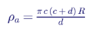
The method requires fewer probe moves for deep surveys and produces stronger potential signals at wide spacings, which makes it useful for large substations and for sites where very deep soil layers control the grid resistance.
19.2 Seasonal and moisture effects
Soil resistivity rises as soil dries and rises sharply when soil freezes. Surface layers are affected most. A grid measured shortly after heavy rain may show a resistance much lower than its dry-season or frozen-ground value. Good practice:
- Record conditions at the time of every survey and test.
- Design for the worst credible season, using conservative upper-layer resistivity in arid regions and frozen-layer models in northern states.
- Bury conductors below the frost line where practical, so the grid remains in stable soil.
- Use deep rods to reach permanently moist strata in dry regions.
20. Improving a grounding system
When testing or analysis shows that a grounding system does not meet its criteria, several remedies are available. Each acts on a different part of the problem:
| Remedy | Primary effect | Notes |
|---|---|---|
| Closer mesh spacing in critical areas | Reduces mesh (touch) voltage | Most effective where touch voltage governs |
| Grid extension beyond the fence | Reduces outside-the-fence touch voltage and grid resistance | Requires space and property rights |
| Deep ground rods | Reduces grid resistance in layered soil with low-resistivity lower layers | Effective only if lower layers are more conductive |
| Ground enhancement material around conductors | Reduces local contact resistance | Limited effect on large grid resistance; long-term stability must be confirmed |
| Thicker or higher-resistivity surface layer | Increases tolerable touch and step voltages | Must be maintained; asphalt can provide very high resistivity |
| Additional shield wires or lower-resistance shield wires | Reduces split factor and GPR | Coordinate with line design |
| Faster fault clearing | Increases tolerable voltages | Coordinate with protection design |
| Isolation of transferred-voltage paths | Removes remote hazards | Isolation devices for communication circuits, insulating sections in pipes and rails |
| Remote grids connected by conductors | Reduces overall resistance | Must consider transferred voltage and conductor routing |
The right combination depends on which criterion fails and why. Reducing resistance does not necessarily reduce touch voltage enough, while closer mesh spacing may solve touch voltage without changing resistance much. A computer model of the grid allows options to be compared quantitatively before construction.
21. Ground potential rise and communication circuits
Telecommunication and control circuits entering a substation — copper telephone lines, SCADA circuits and leased circuits — can carry dangerous voltages out of the station during a fault, or bring remote earth potential into the station. IEEE 367 provides methods for determining the zone of influence of GPR, and IEEE 487 series standards address protection of wireline communication facilities serving electric supply locations. Common solutions include:
- Fiber-optic isolation for communication circuits entering high-GPR stations.
- Isolation transformers and neutralizing transformers for metallic circuits.
- Coordination with the communication provider on the calculated GPR and zone of influence.
Increasingly, fiber-optic communication eliminates metallic circuits altogether, but legacy copper circuits remain at many older substations and must be evaluated whenever fault levels increase.
22. A practical grounding test report
A complete grounding test report allows the results to be trusted and compared over the life of the facility:
- Purpose and scope: which tests were performed and why.
- Site description: grid layout, connected shield wires, neutrals and cable sheaths, and whether they were connected during testing.
- Test equipment: instrument types, serial numbers and calibration dates.
- Test layout: probe locations with coordinates, lead routes, distances and angles.
- Conditions: weather, soil moisture, temperature and recent rainfall.
- Raw data: all readings, including fall-of-potential curves and resistivity data at every spacing.
- Analysis: soil model, interpretation of curves, scaling of touch and step voltages, and comparison with design and tolerable values.
- Deficiencies: each defect, its location, photographs and recommended corrective action.
- Conclusions: whether the system meets its criteria, and any limitations of the testing.
- Recommendations: maintenance intervals and conditions that should trigger retesting.
23. Grounding at BESS and inverter-based plants: practical test points
Battery and solar plants contain many small, distributed pieces of equipment, each with its own grounding connections. A commissioning test plan typically covers:
- Each inverter skid and pad-mount transformer: point-to-point resistance from the enclosure and transformer tank to the main grid.
- Battery containers: bonding of each container, rack frames and fire suppression equipment; continuity to the site grounding system.
- Collector system: cable shield grounding at each termination and splice, and the grounding transformer neutral connection.
- Fence and gates: bonding and outside-the-fence touch voltage near the project substation.
- Array structures: sampling of racking and pile bonding across the array, with emphasis on combiner and recombiner locations.
Because these plants cover large areas with long cable runs, Keentel's test plans prioritize locations where people work most often and where fault currents are highest, rather than attempting exhaustive testing of every structure.
24. How Keentel Engineering helps
Keentel Engineering provides grounding design, testing oversight and safety analysis for utilities, renewable and storage developers, data centers and industrial facilities, from 4 kV to 765 kV.
| Stage | Keentel scope | Outcome |
|---|---|---|
| Soil investigation | Wenner and Schlumberger survey planning, data review and multilayer soil modeling | An accurate basis for design |
| Grounding design | IEEE 80 grid design, conductor sizing, current split and GPR analysis, touch and step calculations | Safe, cost-effective grounding systems |
| Computer modeling | Detailed grid modeling for complex soils, fences, transferred voltages and large plants | Confidence where hand calculations fall short |
| Test planning and witnessing | IEEE 81 test procedures, lead routing, scaling methods and acceptance criteria | Reliable, meaningful test results |
| Commissioning review | ANSI/NETA ATS test review, deficiency identification and corrective action | Facilities that are safe on day one |
| Existing facility assessments | Fault current growth reviews, condition assessments and upgrade designs | Continued safety as systems change |
| Renewable, BESS and data center projects | Substation, collector and campus grounding coordinated with NEC, NFPA 855 and NFPA 780 | Integrated grounding across the facility |
Why clients choose Keentel Engineering
- Design and testing expertise together: we know what the measurements must prove because we design the systems they verify.
- Standards depth: IEEE 80, IEEE 81, IEEE 142, NESC, NEC and ANSI/NETA requirements applied correctly.
- Practical field experience: test plans that work on real sites with energized equipment, long leads and noisy environments.
- Licensed professional engineering: a Florida-registered firm with offices in Tampa, Austin, Sacramento and Baltimore, supporting projects nationwide.
- Clear deliverables: reports that owners, utilities and inspectors can act on.
Need grounding design, testing oversight or a safety assessment? Talk to Keentel Engineering at (813) 389-7871, contact@keentelengineering.com, or book a 15-minute scoping call at calendly.com/keentel-engineering/15min.
Part C — Case Studies
The following are illustrative scenarios based on conditions typical of US substation, renewable and data center projects. They show how Keentel Engineering approaches grounding problems; site details are generalised and figures are rounded.
Case Study 1 — 230 kV substation expansion: fault current growth and touch voltage
Situation. A utility plans to add a 230 kV line terminal and a second transformer at a substation built decades earlier. Updated fault studies show the maximum ground fault current has nearly doubled since the original design.
Analysis. Keentel reviews original drawings, performs a new soil resistivity survey and builds a multilayer computer model of the grid. With the new fault current and a revised current split that accounts for shield wire changes, mesh voltages exceed tolerable limits in two areas, and touch voltage outside the fence near a gate exceeds limits where the crushed rock has degraded.
Engineered solution. Keentel designs supplemental grid conductors in the high-voltage areas, a perimeter conductor outside the fence, extended and refreshed crushed rock and gate bonding modifications. A fall-of-potential test plan with frequency-selective instruments and long current leads is developed for commissioning.
Outcome. Calculated touch and step voltages meet IEEE 80 limits with margin for further fault growth, and commissioning tests confirm grid resistance within the modeled range.
Case Study 2 — 300 MW solar plant: high-resistivity soil at a 345 kV substation
Situation. A solar developer plans a 345 kV project substation on a desert site. Initial design assumed 300 Ω·m soil based on regional data.
Analysis. Keentel's resistivity survey finds a dry upper layer above 1,500 Ω·m over deeper soil near 400 Ω·m. With the actual soil model, the original grid design produces touch voltages above tolerable limits and a GPR high enough to create transferred voltage concerns on a nearby communication line.
Engineered solution. Keentel redesigns the grid with closer mesh spacing in the yard, deep ground rods reaching the lower-resistivity layer, a thicker high-resistivity surface layer and isolation measures for the communication circuit. Collector system grounding is coordinated with the main power transformer and grounding transformer design.
Outcome. The design meets IEEE 80 criteria, the transmission owner accepts the grounding report, and commissioning tests confirm the predicted resistance.
Case Study 3 — data center campus: bonding defects found before energization
Situation. A new data center campus with a 138 kV substation and multiple 13.8 kV buildings is approaching energization. The owner wants independent verification of grounding before commissioning.
Analysis. Keentel develops a testing scope covering fall-of-potential testing of the substation grid, point-to-point continuity of all major equipment, building grounding electrode systems and data hall bonding networks. Testing identifies several high-resistance connections: a generator enclosure grounded only through its mounting bolts, a severed grid conductor near a duct bank and missing bonding jumpers across cable tray expansion joints.
Engineered solution. Keentel documents each deficiency, recommends corrective work and witnesses retesting. The substation grid resistance and bonding results are recorded as the baseline for the campus maintenance program.
Outcome. All deficiencies are corrected before energization, and the owner receives a complete grounding verification report for its insurer and operations team.
Part D — Technical FAQ: Grounding System Testing
They describe the same function. US practice and IEEE standards use grounding; many other countries use earthing.
People are protected by keeping touch, step and transferred voltages within tolerable limits. Those voltages depend on grid geometry, surface material, current split and clearing time, not only on resistance.
GPR is the voltage of the grounding system relative to remote earth during a fault, equal to the grid current times the grid impedance.
It is the fraction of the total ground fault current that flows from the grid into the earth. The rest returns through shield wires, neutrals and cable sheaths.
IEEE 80 uses body current limits based on body weight and shock duration, a 1,000 Ω body resistance and the resistivity of the surface layer. Tolerable voltage decreases with longer shock duration.
High-resistivity crushed rock adds resistance between a person's feet and the soil, greatly increasing tolerable touch and step voltages. It must remain clean and well-drained.
A four-probe soil resistivity test with equal spacing. Current is injected between the outer probes and voltage is measured between the inner probes. Apparent resistivity equals 2π times the spacing times the measured resistance.
Roughly to a depth comparable to the probe spacing. Measurements at several spacings are used to build a layered soil model.
The IEEE 81 reference method for measuring electrode or grid resistance. Current is injected to a remote probe, and voltage is measured with a potential probe at various positions to find the true resistance.
For a hemispherical electrode in uniform soil, the true resistance is measured with the potential probe at 61.8% of the distance to the current probe. It is an approximation for large grids and non-uniform soils.
Far enough to produce a flat region in the fall-of-potential curve, typically several times the largest dimension of the grid. Large substations may need leads of hundreds of meters or more.
Not meaningfully. Clamp-on testers need a single loop and work well on multi-grounded poles or structures, but not on large grids with many parallel paths.
They must be scaled from the test current to the design grid current. A reading without the test current and scaling basis cannot be compared with tolerable limits.
ANSI/NETA ATS recommends investigating point-to-point resistance values above 0.5 Ω. Comparing similar connections and trending results is also important.
A single rod, pipe or plate electrode must be supplemented by an additional electrode unless it has a resistance to earth of 25 Ω or less.
A voltage carried outside the grid by a conductor connected to it, such as a fence, rail, pipe or communication cable. A person touching that conductor remotely can be exposed to nearly the full GPR.
Touch and step voltages scale with grid current. As system fault levels increase, an older grid may no longer meet tolerable limits.
At commissioning, after modifications or major faults, and periodically as part of maintenance, often every few years depending on utility practice, soil corrosivity and theft risk.
IEEE 80 and IEEE 81 for substations, IEEE 142 and IEEE 1100 for industrial and electronic systems, the NESC for utility facilities, NEC Article 250 for premises wiring, and ANSI/NETA ATS and MTS for acceptance and maintenance testing.
Placing the current probe too close or reporting unscaled touch and step voltages. Both produce numbers that look precise but do not represent the actual safety of the installation.
References and Further Reading
Links were current at publication (October 2026).
- IEEE Std 80, Guide for Safety in AC Substation Grounding. IEEE.
- IEEE Std 81, Guide for Measuring Earth Resistivity, Ground Impedance, and Earth Surface Potentials of a Grounding System. IEEE.
- IEEE Std 142, Recommended Practice for Grounding of Industrial and Commercial Power Systems (Green Book). IEEE.
- IEEE Std 367, Recommended Practice for Determining the Electric Power Station Ground Potential Rise and Induced Voltage from a Power Fault. IEEE.
- IEEE Std 1100, Recommended Practice for Powering and Grounding Electronic Equipment. IEEE.
- ANSI C2, National Electrical Safety Code. IEEE.
- NFPA 70, National Electrical Code, Article 250; NFPA 780, Standard for the Installation of Lightning Protection Systems; NFPA 70E. National Fire Protection Association.
- ANSI/NETA ATS, Standard for Acceptance Testing Specifications; ANSI/NETA MTS, Standard for Maintenance Testing Specifications. InterNational Electrical Testing Association.
- OSHA 29 CFR 1910.269, Electric Power Generation, Transmission, and Distribution. US Department of Labor.
Disclaimer
This article is general technical information for educational purposes. It is not engineering advice for any specific project and does not create a professional relationship. Soil data, fault currents, split factors, calculated voltages and acceptance values are illustrative; actual grounding designs and test programs must follow the current editions of applicable standards, utility requirements, equipment manufacturer instructions and project-specific engineering analysis, sealed by a licensed professional engineer where required. Grounding tests at energized facilities involve serious hazards and must be performed by qualified personnel following applicable safety rules.
Case studies are illustrative scenarios based on typical project conditions, not records of specific client projects. Figures are rounded and indicative.
IEEE, NFPA, NETA, OSHA, SES CDEGS, ETAP, WinIGS and other names are the property of their respective owners. Keentel Engineering is not affiliated with or endorsed by these organisations or any software or equipment vendor.
| Office | Address | Phone |
|---|---|---|
| Head Office — Tampa | 400 N Ashley Dr STE #2600, Tampa FL 33602 | (813) 389-7871 |
| Austin | 5900 Balcones Drive STE 100, Austin TX 78731 | (512) 591-0752 |
| Sacramento | 1401 21st St Ste R, Sacramento CA 95811 | (916) 913-4524 |
| Baltimore | 306 W Redwood St STE 200, Baltimore MD 21201 | (410) 225-2181 |

About the Author:
Sandip "Sonny" R. Patel, P.E.
IEEE Senior Member · Founder & CEO, Keentel Engineering
In 1995, Sonny Patel earned his Electrical Engineering degree from the University of Illinois. But degrees don't build legacies — action does.
For three decades, he has worked the power industry from every side of the table: 16 years as a utility engineer at Exelon/Commonwealth Edison; generation leadership across hydroelectric, industrial steam turbine, and a 9 GW renewable fleet; NERC Regional Entity Senior Compliance Engineer and Audit Team Lead, auditing some of the nation's largest utilities; and testing and commissioning lead on equipment up to 765 kV — the very top of the North American grid.Utility. Generator. Regulator. Consultant. Few engineers have seen all four seats. Fewer still have sat in them.
His experience spans nuclear, hydro, conventional generation, renewables, oil and gas, mining — and today's data centers, where he is authoring a three-book series on data center design. He is a Licensed Professional Engineer in six states and a Licensed Electrical Contractor in Florida (Unlimited EC) — he doesn't just design the work; he's qualified to stand behind its execution.Today, as Founder and CEO of Keentel Engineering, Sonny leads a nationwide team of engineers delivering substation design, power system studies, NERC compliance, and commissioning — done right, coast to coast.Three decades. Every side of the table. One standard: accountable engineering.
Services

Let's Discuss Your Project
Let's book a call to discuss your electrical engineering project that we can help you with.
About the Author:
Sandip "Sonny" R. Patel, P.E.
IEEE Senior Member · Founder & CEO, Keentel Engineering
In 1995, Sonny Patel earned his Electrical Engineering degree from the University of Illinois. But degrees don't build legacies — action does.
For three decades, he has worked the power industry from every side of the table: 16 years as a utility engineer at Exelon/Commonwealth Edison; generation leadership across hydroelectric, industrial steam turbine, and a 9 GW renewable fleet; NERC Regional Entity Senior Compliance Engineer and Audit Team Lead, auditing some of the nation's largest utilities; and testing and commissioning lead on equipment up to 765 kV — the very top of the North American grid.
Utility. Generator. Regulator. Consultant. Few engineers have seen all four seats. Fewer still have sat in them.
His experience spans nuclear, hydro, conventional generation, renewables, oil and gas, mining — and today's data centers, where he is authoring a three-book series on data center design. He is a Licensed Professional Engineer in six states and a Licensed Electrical Contractor in Florida (Unlimited EC) — he doesn't just design the work; he's qualified to stand behind its execution.
Today, as Founder and CEO of Keentel Engineering, Sonny leads a nationwide team of engineers delivering substation design, power system studies, NERC compliance, and commissioning — done right, coast to coast.Three decades. Every side of the table. One standard: accountable engineering.
Leave a Comment
Thank you for contacting us.
We will get back to you as soon as possible.
We will get back to you as soon as possible.
Oops, there was an error sending your message.
Please try again later.
Please try again later.
Related Posts
By SANDIP R PATEL
•
October 13, 2026
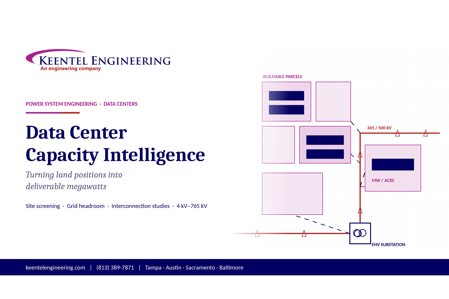
Plan data center capacity with land screening, MW-per-acre estimates, grid power availability and interconnection feasibility studies from Keentel Engineering.
By SANDIP R PATEL
•
October 11, 2026
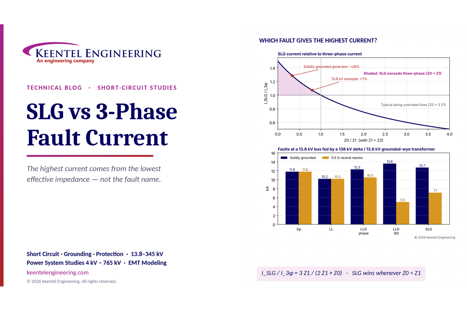
Learn which fault produces the highest current at a bus, why SLG faults can exceed three-phase faults, and how symmetrical components determine fault duty.
By SANDIP R PATEL
•
October 11, 2026
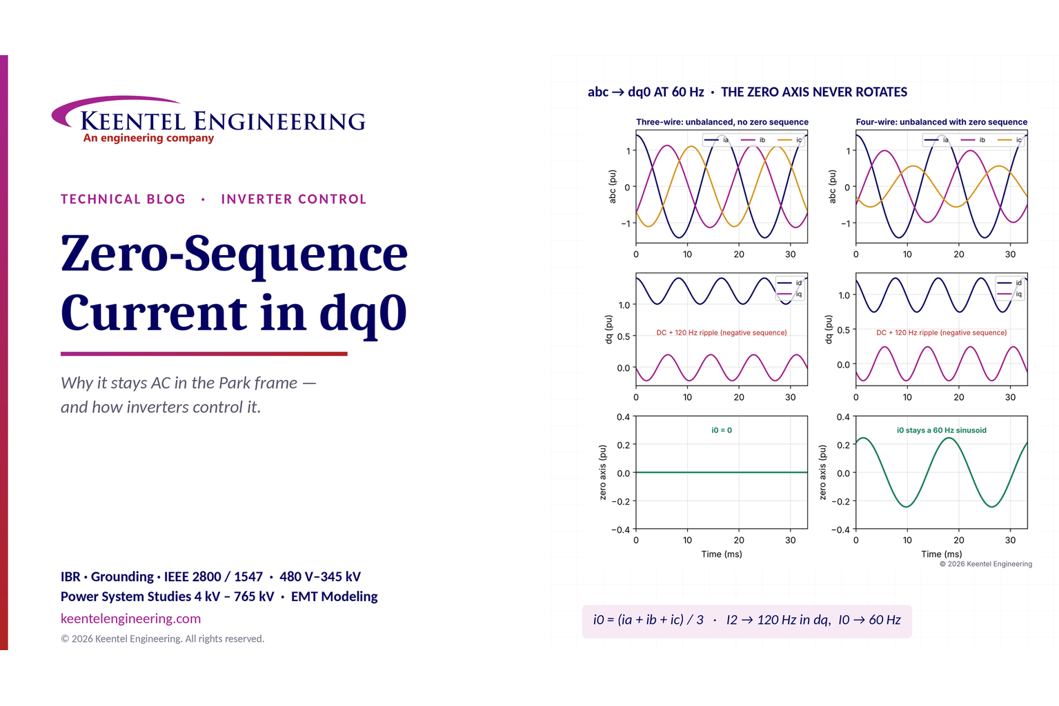
Learn why zero-sequence current pulsates in the dq0 frame, how Park's transformation works, and how inverter controls handle unbalance and ground faults.
By SANDIP R PATEL
•
October 11, 2026
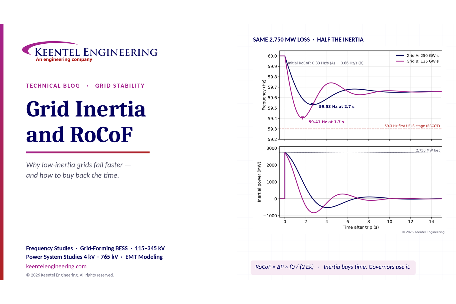
Explore grid inertia, RoCoF and frequency response, with swing equation calculations, frequency nadir analysis and US power system simulation examples.
By SANDIP R PATEL
•
October 11, 2026
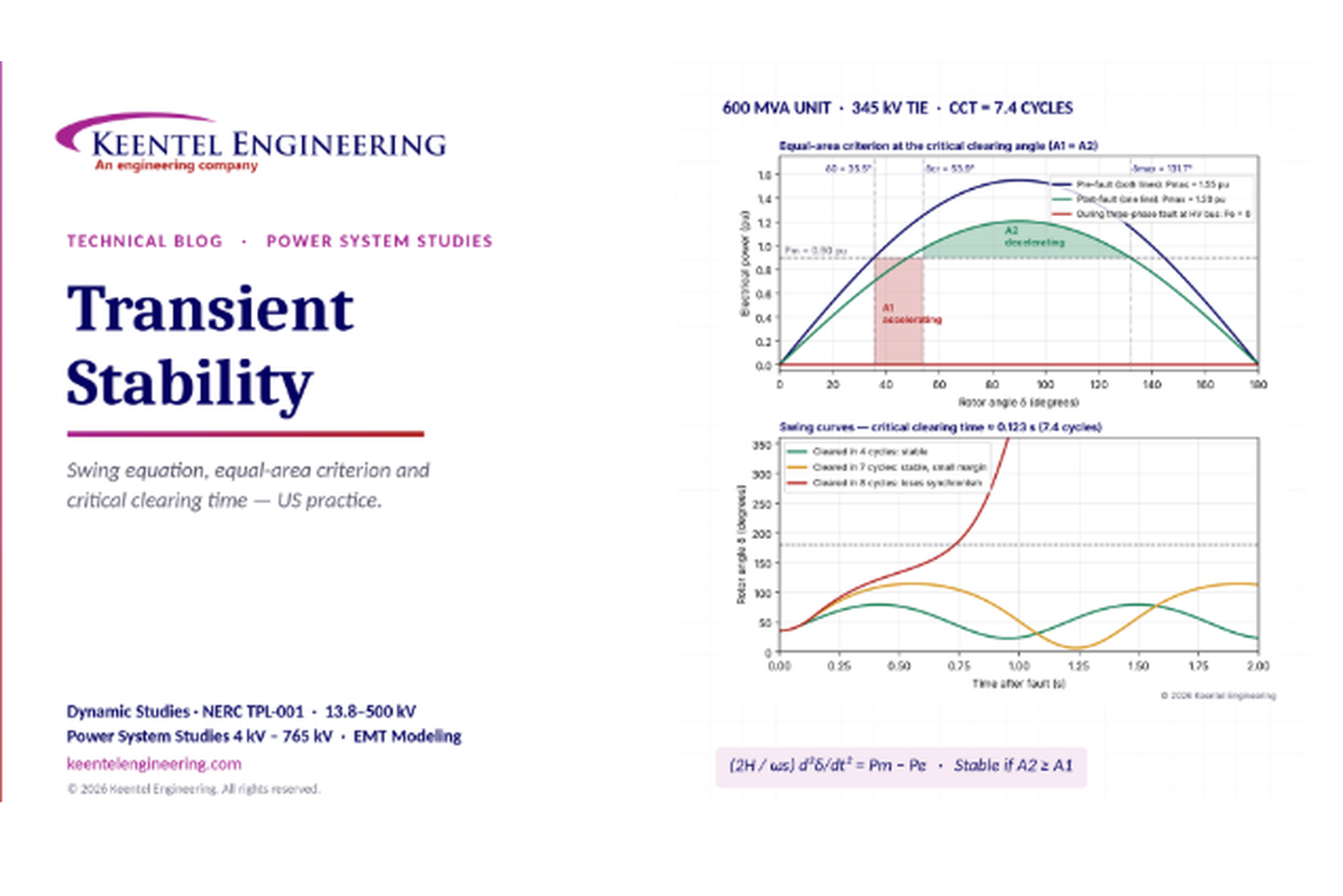
Learn transient stability analysis, swing equation, equal-area criterion and critical clearing time with a 345 kV worked example and NERC TPL-001 guidance.
By SANDIP R PATEL
•
October 11, 2026
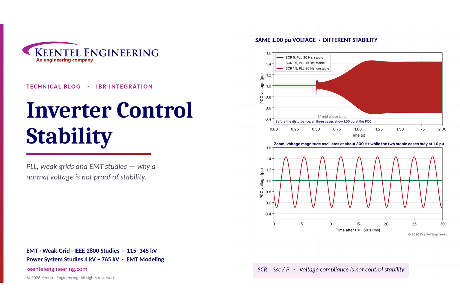
Learn why inverter controls become unstable in weak grids, how PLL bandwidth and SCR affect stability, and how PSCAD EMT studies identify and mitigate oscillations.
By SANDIP R PATEL
•
October 11, 2026
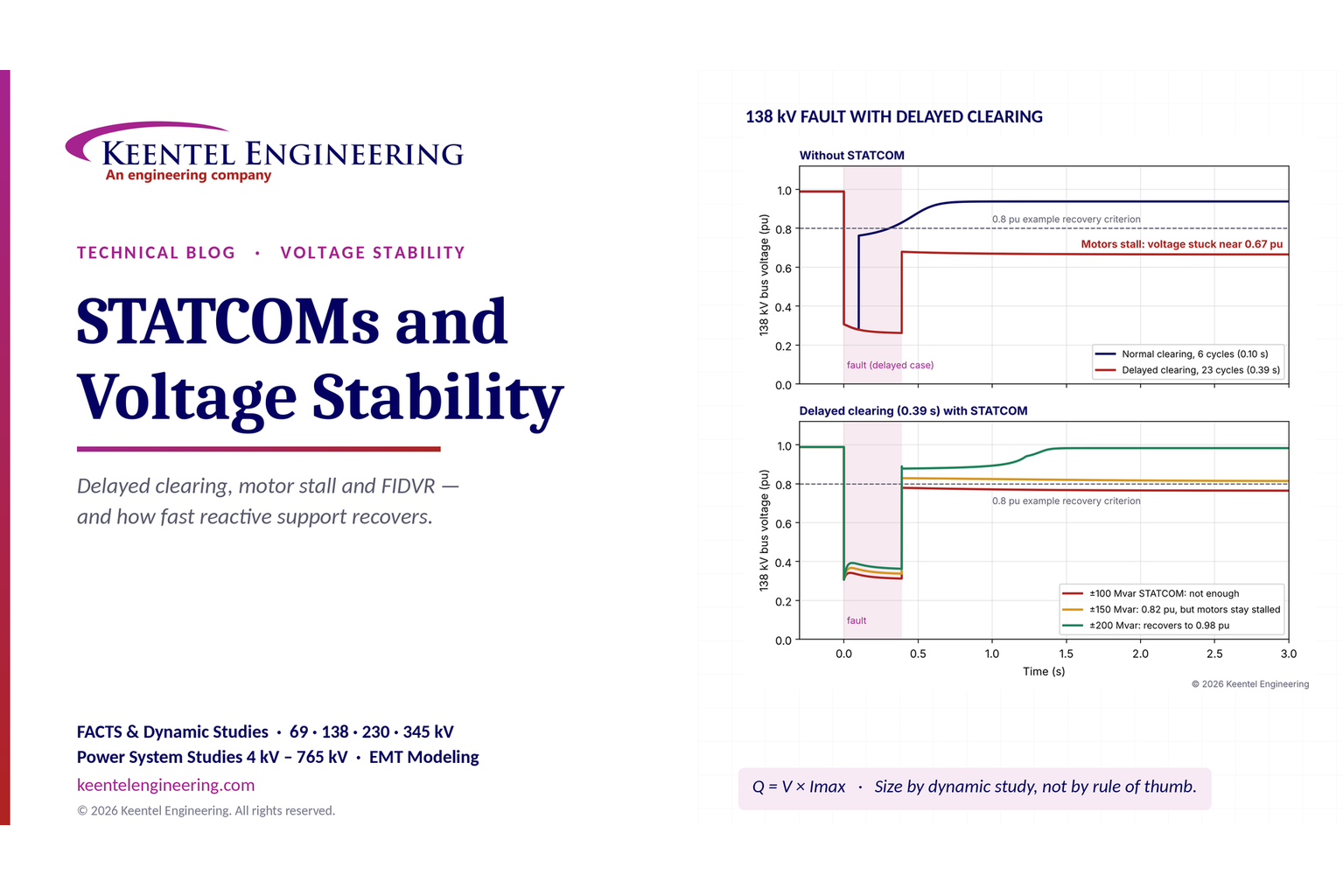
Learn how STATCOMs improve voltage stability and prevent FIDVR. Explore reactive power sizing, delayed fault clearing, NERC criteria and 138 kV simulation results.
By SANDIP R PATEL
•
October 10, 2026
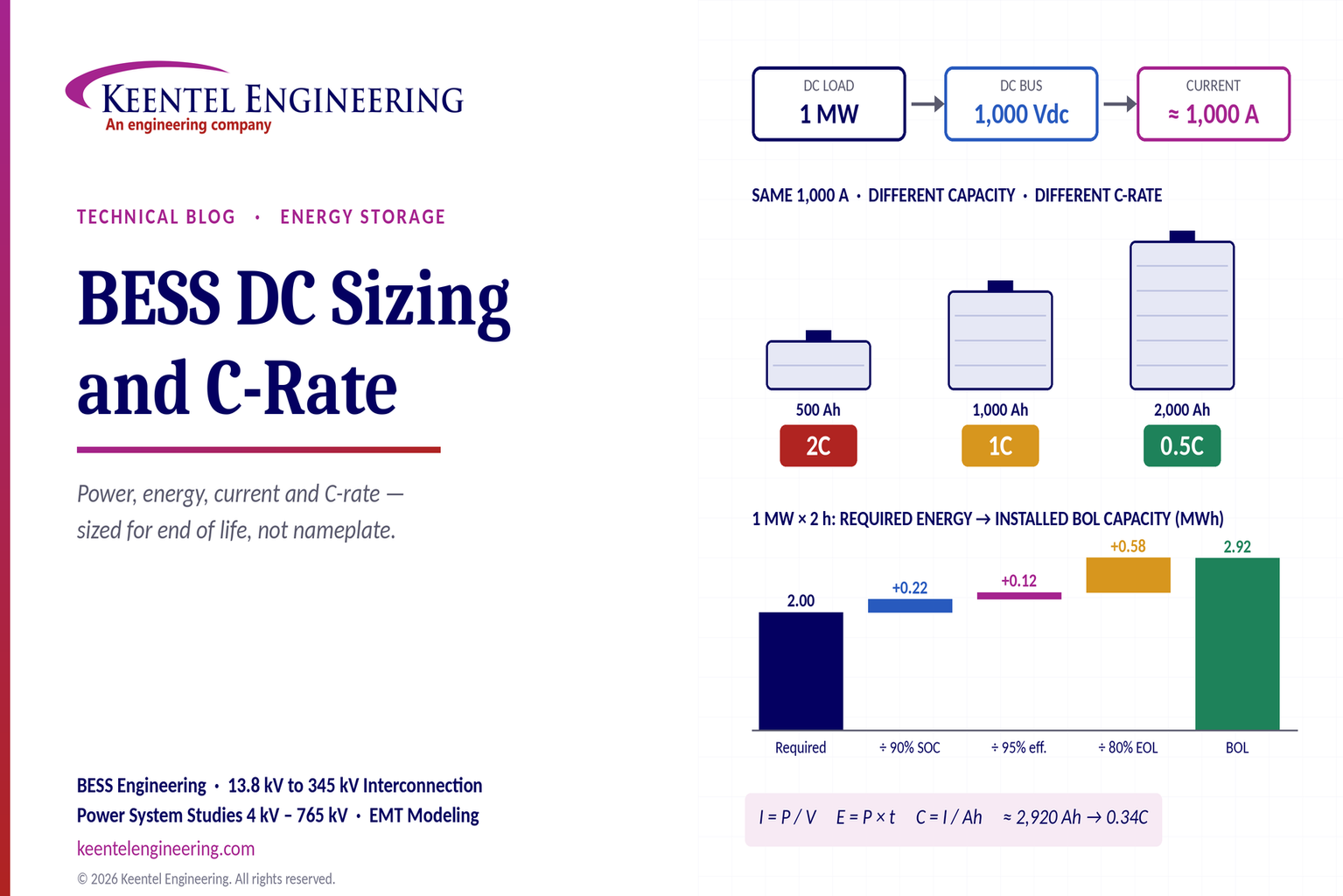
Learn BESS DC sizing with power, energy, current and C-rate calculations, battery losses, degradation and a 100 MW/400 MWh utility-scale example.
By SANDIP R PATEL
•
October 10, 2026
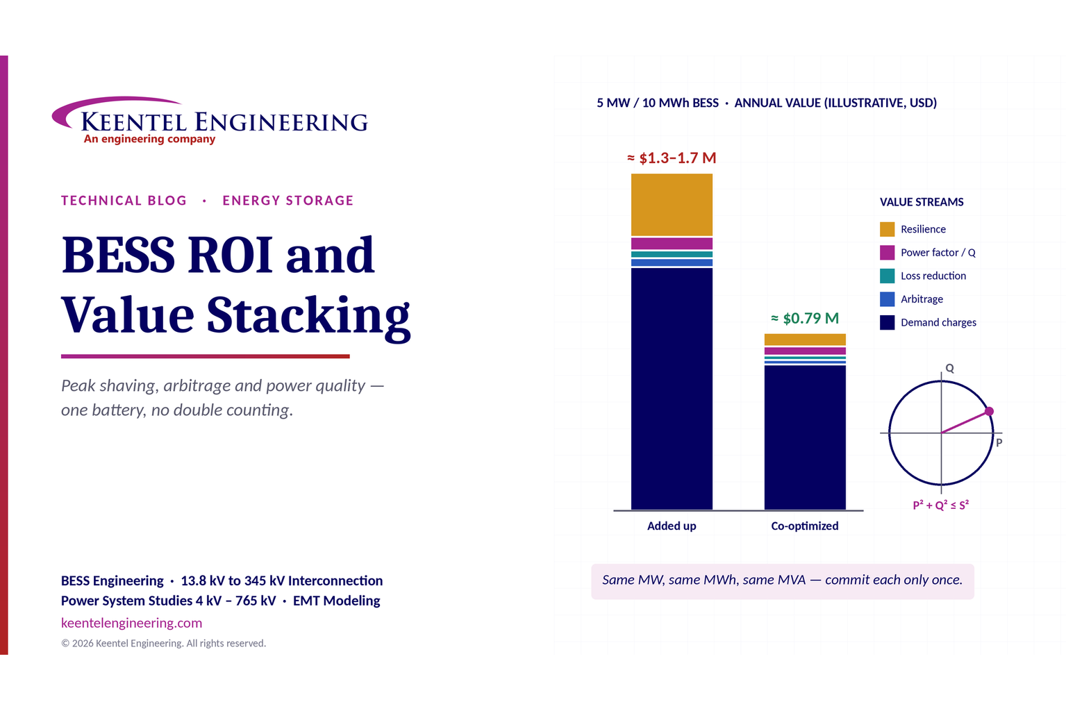
Learn how BESS ROI is calculated using peak shaving, energy arbitrage, power quality and battery storage economics, with a practical 5 MW/10 MWh example.