A Coordinated Electric System Interconnection Review—the utility’s deep-dive on technical and cost impacts of your project.
Challenge: Frequent false tripping using conventional electromechanical relays
Solution: SEL-487E integration with multi-terminal differential protection and dynamic inrush restraint
Result: 90% reduction in false trips, saving over $250,000 in downtime
The three operating regions you have to design to
| Device | Output vs voltage | Response | Best suited to | Main limitations |
|---|---|---|---|---|
| Mechanically switched capacitor or reactor | Proportional to voltage squared | Seconds; discrete steps; limited switching operations per day | Steady-state reactive supply, voltage profile, loss reduction | No dynamic capability; step voltage change on switching; capability collapses when most needed |
| Static var compensator | Capacitive branches proportional to voltage squared | A few cycles; continuously controllable | Continuous control where cost matters and deep voltage support is not the driver | Square-law capability loss; harmonic filters are part of the plant and interact with the network |
| STATCOM | Approximately proportional to voltage — constant current capability | One to two cycles closed loop; converter response faster still | Voltage stability margin, weak interconnections, fast disturbance recovery, flicker and unbalance compensation | Higher capital cost; converter losses; adds a converter and its control dynamics to the network |
| Synchronous condenser | Governed by machine capability and excitation | Excitation response in the hundreds of milliseconds; inherent inertial response instantaneous | System strength and inertia, short-circuit contribution, black start support | Rotating plant with maintenance and losses; slower controlled response than a converter |
| STATCOM with energy storage | Reactive as a STATCOM, plus real power within the storage rating | As STATCOM for reactive; real power limited by storage | Where a real power deficiency is part of the problem | Cost and complexity of the storage; different failure and maintenance profile |
| Stage | Keentel scope | Outcome |
|---|---|---|
| Screening | Series-compensation proximity, radial contingency review, UIF and short-circuit ratio screening, frequency scans | Early identification of which SSO types apply |
| Detailed studies | PSCAD/EMTDC EMT studies with vendor real-code models, impedance-based and frequency-scan analysis | Clear evidence of stability margins or risk |
| Model quality | EMT model review, benchmarking against positive-sequence models, model acceptance support | Models that system operators accept |
| Mitigation | Control retuning recommendations with vendors, SSDC and bypass logic requirements, protection and monitoring specifications | Practical, coordinated solutions |
| Interconnection support | SSR and SSO study reports for ISO and utility requirements, response to reviewer comments | Fewer delays in the interconnection process |
Resilience: designing CDUs to the facility Tier objective
Liquid cooling makes heat removal more critical, not less. Cold plates hold only seconds of thermal buffer. If TCS flow stops, processors throttle or shut down very quickly. Resilience design must therefore cover:
- Pump redundancy: N+1 pumps at minimum, with automatic changeover.
- CDU redundancy: N+1 CDUs on a common TCS header, or 2N CDUs serving A and B manifolds for fault-tolerant designs.
- Power to CDUs: dual-corded CDUs fed from A and B sources, with pumps and controls on UPS power so coolant keeps flowing through a utility failure and generator start. This is the liquid-cooling equivalent of continuous cooling.
- Facility water continuity: chilled water or condenser water must also continue, through thermal storage, UPS-backed pumps or a high enough FWS temperature that the TCS can coast on stored thermal mass for the transfer period.
- Concurrent maintainability: isolation valves so any CDU, pump, filter or manifold section can be serviced without stopping the others.
- Leak management: leak detection, drip trays, automatic isolation valves and procedures for fluid spills.
Electrical engineering considerations
CDUs and liquid-cooling plants are electrical loads with their own design requirements:
- Pump motors and VFDs. Large CDUs use variable-frequency drives on their pump motors. These introduce harmonic current that must be included in the facility's harmonic study and IEEE 519 evaluation.
- Critical mechanical load on UPS. Putting CDU pumps on UPS increases UPS and battery sizing. The mechanical UPS load must be included in redundancy and ride-through calculations.
- Feeder and protection design. Dual feeds, automatic transfer, selective coordination and arc-flash labelling apply to CDU power distribution just as they do to IT power.
- Generator transient response. CDU pumps restarting together after a transfer create motor inrush on the generators. Staged restarts and soft acceleration reduce the step load.
- Load dynamics. AI training loads can swing rapidly between high and low power. Cooling controls must track those swings without temperature overshoot, and electrical systems must handle both the IT and the cooling load changes.
Commissioning a liquid-cooled data hall
- Flush and clean the TCS piping and manifolds to the specified cleanliness, using high-purity flush water.
- Fill and vent with the specified coolant, verifying glycol concentration and chemistry.
- Pressure test for leaks at design and test pressures, including quick-disconnect fittings.
- Verify sensors and controls: flow meters, temperature sensors, pressure transmitters, leak detection and BMS points.
- Load test with heat load banks connected through the cold-plate interfaces or rack manifolds, across the operating range.
- Prove the heat balance on both loops at several load steps, and the approach temperature against the design.
- Test failure scenarios: pump failure, CDU failure, power transfer to generator, valve failure and loss of facility water, confirming temperatures stay within the IT vendor's limits.
How Keentel Engineering helps
Keentel Engineering supports data center owners, developers and EPCs with the electrical engineering that liquid-cooled facilities depend on, and coordinates with the mechanical engineer of record and cooling vendors on the integrated design.
Harmonic Resonance in Power Systems: Causes and Mitigation
October 21, 2026 | Blog
Part A — Harmonic Resonance at a Glance
A plant adds a power factor correction capacitor bank. The goal is sensible: reduce reactive power demand, avoid a utility power factor penalty, and free up transformer capacity. Weeks later, capacitor fuses start to operate. Transformers run hotter than their loading suggests. Voltage distortion climbs. A variable frequency drive that ran flawlessly for years begins to trip on DC bus overvoltage for no apparent reason.
The instinctive response is to hunt for the equipment that produces harmonics. That is only half of the investigation. The other half is the network itself. Every electrical network has a frequency-dependent impedance, set by its transformers, cables, capacitors, reactors, motors and other connected equipment. At certain frequencies, the network can amplify harmonic currents and voltages that it never created. The drive did not change. The network did.
The two mechanisms in one paragraph each
Parallel resonance. The network inductance (utility source and transformers) and a shunt capacitance (capacitor banks, cables) appear in parallel to a harmonic current source. At the resonant frequency their reactances cancel, and the impedance seen by the harmonic source rises sharply, limited only by resistance and load damping. A modest harmonic current then produces a large harmonic voltage, distorting the voltage at every load on that bus.
Series resonance. An inductance and a capacitance appear in series in one current path — classically, a distribution transformer feeding a capacitor bank on its secondary. At the resonant frequency the path impedance collapses toward its resistance. A modest harmonic voltage already present on the supply then drives a large harmonic current through the transformer and capacitor.
What Keentel's frequency scan shows
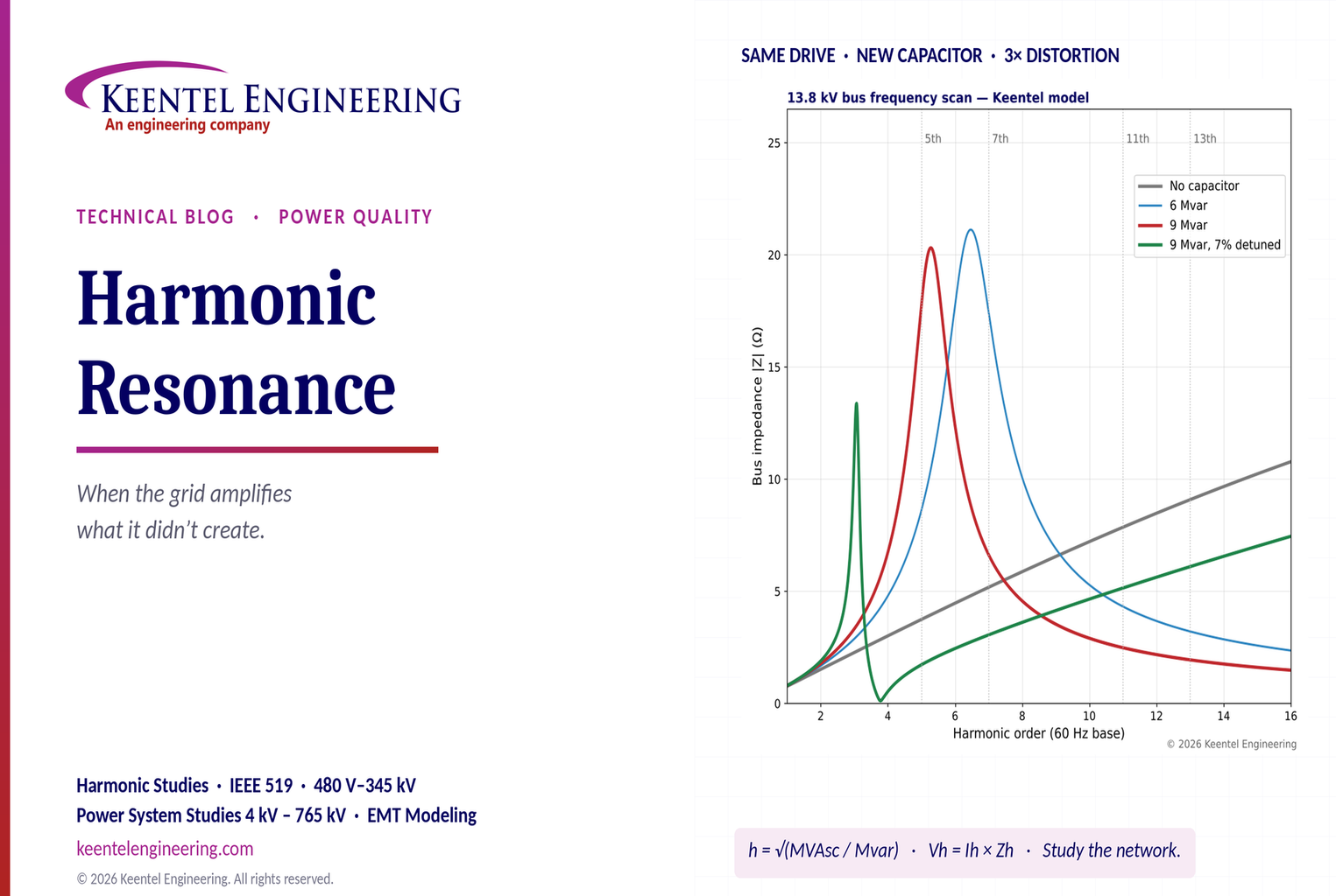
Keentel Engineering modeled a 13.8 kV industrial bus with 250 MVA of available short-circuit capacity, an 8 MW resistive and motor load, and a 4 MW six-pulse drive load injecting a typical characteristic harmonic spectrum. The drive and its harmonic currents were held constant. Only the capacitor configuration changed.
| Configuration | Parallel resonance (harmonic order) | Bus impedance at 5th (pu) | 5th harmonic voltage | Voltage THD |
|---|---|---|---|---|
| No capacitors | None | 1.75 | 1.6% | 2.8% |
| 3 Mvar | 9.2 | 5.26 | 2.2% | 4.3% |
| 6 Mvar | 6.5 | 8.62 | 3.6% | 5.7% |
| 9 Mvar | 5.3 | 17.8 | 7.5% | 7.7% |
| 9 Mvar with 7% detuning reactor | 3.1 (below tuning) | 1.72 | 0.7% | 1.7% |
| 9 Mvar with a second transformer paralleled | 6.7 | 5.23 | 2.2% | 4.9% (7th rises to 4.3%) |
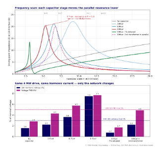
Figure 1. Top: driving-point impedance at the 13.8 kV bus for each configuration. Bottom: resulting 5th harmonic voltage and total harmonic distortion against IEEE 519-2022 limits for buses from 1 kV to 69 kV.
Three lessons from the scan
- The capacitor bank did not create a single ampere of harmonic current, yet it nearly tripled voltage distortion. With 9 Mvar in service, the 5th harmonic current flowing in the capacitor bank is about 141 A — more than four times the 33 A of 5th harmonic current the drive injects. The rest circulates between the capacitor and the utility source.
- Every switching state is a different network. Each capacitor stage moves the resonance lower. Paralleling a second transformer moves it higher — away from the 5th, but closer to the 7th. A design that is safe in one configuration can be unsafe in another.
- Detuning works, but it moves the resonance rather than removing it. A 7% reactor in a 60 Hz system tunes the capacitor branch to about 227 Hz (3.78th harmonic) and creates a new parallel resonance near the 3rd harmonic. That is acceptable only if there is little 3rd harmonic current on the bus.
Resonance is not a fault. It is a property of the network at a particular frequency. The risk arises from the interaction between harmonic sources and that frequency response — which is why the right question is not only "who is generating the harmonics?" but "what is the network doing with them?"
Engineering review of common published examples
Resonance is often explained with idealized examples. Keentel reviewed the typical published numbers and found the physics correct but several details that matter in US practice.
| Common statement | Keentel's check |
|---|---|
| Parallel RLC with L = 5 mH, C = 80 µF, R = 100 Ω resonates at 251.65 Hz with Q = 12.65 | Correct: 1 ÷ (2π√LC) = 251.6 Hz and Q = R√(C/L) = 12.65. Peak impedance equals R = 100 Ω. |
| Series RLC with L = 0.8 mH, C = 200 µF, R = 5 Ω resonates at 397.89 Hz with Q = 0.40 | Frequency is correct, but Q = 0.40 means the circuit is overdamped. Its impedance is about 5.4 Ω at 250 Hz and 5.0 Ω at 600 Hz, barely above the 5 Ω minimum, so there is no meaningful series amplification. Real power system series resonances typically have Q of 5 to 30. |
| Amplification tables (20 Ω to 100 Ω, 5% to 20% to 5 Ω, etc.) | Valid as illustrations of V = IZ, but not derived from the stated circuit parameters. Real amplification is set by the network's Q and the distance between the resonance and harmonic frequency. |
| Detuned reactor tuning frequency f = 50 ÷ √p | Correct for 50 Hz systems only. US systems operate at 60 Hz, so f = 60 ÷ √p: 5.7% tunes to 251.2 Hz (4.2nd), 7% to 227 Hz (3.78th) and 14% to 160 Hz (2.67th). |
| "A 189 Hz detuned branch mitigates 5th harmonic resonance" | In a 50 Hz system, 189 Hz is the 3.78th harmonic and sits below the 250 Hz 5th. The same 7% reactor in a 60 Hz system tunes to 227 Hz, below the 300 Hz 5th. The principle holds; the numbers must be recalculated for 60 Hz. |
| Detuning frequencies are branch frequencies, not network resonances | Correct and important. The combined network has a separate parallel resonance below the tuning frequency, which must be checked against 3rd and 2nd harmonic sources. |
Part B — Harmonic Resonance: When the Grid Amplifies What It Didn't Create. An Engineering Guide for US Industrial, Commercial and Utility Systems
1. Why resonance matters more than ever
Harmonic-producing equipment has become the normal load in US facilities. Variable frequency drives control pumps, fans and compressors in water utilities, manufacturing plants and HVAC systems. Uninterruptible power supplies and server power supplies dominate data center loads. Electric vehicle charging stations are appearing at fleet depots, retail sites and highway corridors. Solar, wind and battery inverters connect at 34.5 kV collector systems and 115 kV to 345 kV points of interconnection.
At the same time, capacitors are everywhere. Facilities install power factor correction banks to avoid utility demand charges and power factor penalties. Utilities install distribution and transmission capacitor banks for voltage support. Medium-voltage and high-voltage cable systems — in data center campuses, solar plants and urban networks — add substantial distributed capacitance. Inverter output filters add more.
Inductance from utility sources and transformers is always present. When capacitance and inductance meet, there is a resonant frequency. Whether that frequency coincides with the harmonics actually flowing on the system is often a matter of configuration — and configurations change.
2. Harmonic fundamentals
2.1 Characteristic harmonics
A converter with pulse number p produces characteristic current harmonics at orders:

| Layer | Function | Typical bandwidth |
|---|---|---|
| Phase-locked loop (PLL) | Measures the angle and frequency of the voltage at the point of measurement | 5 to 50 Hz |
| Current control | Regulates d-axis (active) and q-axis (reactive) currents through the output filter | Several hundred hertz to over 1 kHz |
| Outer loops | DC-link voltage control, active power control, reactive power or voltage control | 1 to 20 Hz |
| Plant power controller (PPC) | Regulates POI voltage, reactive power, power factor and frequency response for the whole plant | 0.1 to 2 Hz, with communication delays of tens to hundreds of milliseconds |
Six-pulse drives without input reactors can draw a 5th harmonic current of 30% to 80% of fundamental current. With a 3% to 5% line reactor or DC link choke, the 5th typically falls to about 30% to 40%, and the total current distortion to about 35% to 45%. The illustrative spectrum used in Keentel's model — 20% 5th, 12% 7th, 7% 11th and 5% 13th — represents a drive with input reactance and some load diversity.
2.2 Distortion indices
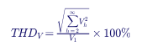
Total harmonic distortion of voltage:
Total demand distortion of current, as used in IEEE 519, is referenced to the maximum demand load current IL rather than the instantaneous fundamental:
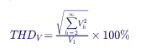
TDD avoids the misleading result where a lightly loaded drive shows a very high current THD that has little system impact.
2.3 The basic relationship
Every harmonic voltage on a bus results from harmonic current flowing through the network impedance at that frequency:

The harmonic current is usually set by the load. The harmonic impedance is set by the network. Resonance is the case where Zh becomes either very large (parallel resonance) or very small (series resonance) at a frequency where significant harmonic current or voltage exists.
3. How network components behave across frequency
| Component | Fundamental model | Behavior at harmonic h |
|---|---|---|
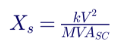
| Utility source | Xs from short-circuit capacity | Reactance rises as h·Xs; resistance rises roughly with h because of skin effect |
| Transformer | Leakage reactance XT from nameplate impedance | Reactance rises as h·XT; winding resistance increases with frequency |
| Overhead line | Series R + jX with small shunt capacitance | Series reactance rises with h; long lines need distributed models |
| Cable | Series impedance plus significant shunt capacitance | Shunt reactance falls as Xc ÷ h; long cables can resonate on their own |
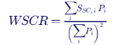
| Shunt capacitor bank | Xc = kV² ÷ Mvar | Reactance falls as Xc ÷ h |
| Induction motor | Subtransient reactance X'' | Reactance roughly h·X''; provides some damping |
| Resistive load | R | Approximately constant; provides important damping |
| Converter loads | Harmonic current sources | Modeled as current injection; modern converters also have frequency-dependent impedance |
Two implications follow. First, inductive reactance grows with frequency while capacitive reactance falls, so every combination of inductance and capacitance has a crossing point. Second, resistive load provides the damping that limits the peak. A lightly loaded plant — at night, on a weekend, or after a process shutdown — often experiences the worst resonance.
Source impedance from short-circuit capacity:
Capacitor reactance from bank rating:
4. Parallel resonance
4.1 The Norton equivalent
To a harmonic current source on a bus, the rest of the network appears as an equivalent inductance Lp (source and transformers), capacitance Cp (capacitor banks and cables) and resistance Rp (loads and losses) in parallel. The bus impedance is:
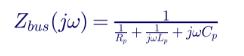
The resonant frequency is:
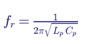
At resonance the inductive and capacitive admittances cancel and the impedance rises to Rp. The quality factor is:
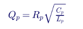
The impedance at resonance is Q times the reactance of either element at that frequency. That is the amplification factor: near resonance, the harmonic voltage is roughly Q times what the same current would produce through the inductive source alone.
4.2 The practical resonance formula
In practice engineers estimate the parallel resonance harmonic order directly from short-circuit capacity and capacitor size:
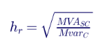
where ZT is the transformer impedance in per unit.
4.3 Worked example: 13.8 kV capacitor stages
A 13.8 kV bus has 250 MVA of available short-circuit capacity. A three-stage 9 Mvar bank is planned, 3 Mvar per stage.
| Stages in service | Capacitor rating | Resonant harmonic order | Resonant frequency |
|---|---|---|---|
| 1 | 3 Mvar | √(250 ÷ 3) = 9.13 | 548 Hz |
| 2 | 6 Mvar | √(250 ÷ 6) = 6.45 | 387 Hz |
| 3 | 9 Mvar | √(250 ÷ 9) = 5.27 | 316 Hz |
The third stage places the resonance within 6% of the 5th harmonic at 300 Hz. Keentel's frequency scan confirms the hand estimate (5.28) and shows the consequence: 5th harmonic voltage rises from 1.6% to 7.5%, and THD from 2.8% to 7.7%.
4.4 Worked example: 480 V power factor correction
A 2,000 kVA, 13.8 kV to 480 V transformer with 5.75% impedance supplies a plant with a large share of six-pulse drives. The plant considers automatic power factor correction in 300 kvar steps.
| Capacitor in service | Resonant harmonic order (transformer only) |
|---|---|
| 300 kvar | 10.8 |
| 600 kvar | 7.6 |
| 900 kvar | 6.2 |
| 1,200 kvar | 5.4 |
At 1,200 kvar, the resonance sits near the 5th harmonic, the dominant drive harmonic. At 600 kvar, it sits near the 7th. Including the utility source impedance lowers each value slightly, moving the 1,200 kvar case even closer to the 5th. An automatic controller cycling through these steps sweeps the resonance across both the 5th and 7th harmonics in the course of a normal day.
4.5 Current amplification in the capacitor
Even though parallel resonance is often described as voltage amplification, it also produces large circulating current. In Keentel's 9 Mvar case:
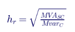
The drive injects 33.5 A of 5th harmonic current. The capacitor carries 141 A at the 5th, and the utility source supplies most of the difference in the opposite phase. A 4.2× current amplification exists inside the plant, invisible to a meter at the drive input.
5. Series resonance
5.1 The series path
When a capacitor bank is connected on the secondary of a transformer, the transformer leakage inductance and the capacitor form a series path from the primary bus to ground. Any harmonic voltage already present on the primary — from other customers, the utility system or upstream converters — drives harmonic current through this path:
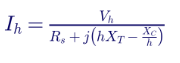
The series resonant order is the same expression as the low-voltage parallel case:
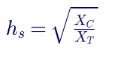
At resonance the current is limited only by resistance. The series quality factor is:
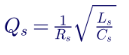
5.2 Worked example: background distortion on a 13.8 kV feeder
A 2,500 kVA, 13.8 kV to 480 V transformer with 5.75% impedance and X/R of 6 supplies a facility with a 1,500 kvar fixed capacitor bank. The 13.8 kV feeder carries 1.5% 5th harmonic voltage from other customers — well within IEEE 519 limits.
On a 2,500 kVA base:
| Quantity | Value at 5th harmonic |
|---|---|
| Transformer reactance h·XT | 5 × 0.0575 = 0.288 pu |
| Capacitor reactance XC ÷ h | (2,500 ÷ 1,500) ÷ 5 = 0.333 pu |
| Net reactance | −0.046 pu |
| Resistance (with √h rise) | ≈ 0.021 pu |
| Path impedance | ≈ 0.051 pu |
| 5th harmonic current | 0.015 ÷ 0.051 ≈ 0.30 pu ≈ 890 A |
The capacitor's fundamental current is about 1,804 A, so the 5th harmonic current is about 49% of fundamental. The facility may have no significant harmonic load of its own, yet its transformer and capacitor are heavily stressed by distortion imported from the utility system. The series resonant order is √(0.333 × 5 ÷ 0.0575) ≈ 5.4, close enough to the 5th to produce large amplification.
5.3 Why the "victim" often looks like the culprit
In series resonance, the facility with the capacitor bank draws large harmonic currents from the utility. A utility power quality meter will see that facility as a major harmonic source and may ask it to reduce emissions under IEEE 519. In reality the facility is absorbing — and amplifying — distortion from elsewhere. A frequency scan and harmonic measurements with phase angle information are needed to identify the true direction of harmonic power flow.
6. Damping and the quality factor
Resonance peaks are limited by damping. The main sources of damping are:
| Damping source | Effect |
|---|---|
| Resistive loads (heating, lighting, process loads) | Strongest damping; reduces Q significantly |
| Induction motor loads | Moderate damping; mainly inductive at harmonic frequencies |
| Transformer and line resistance | Rises with frequency; modest effect |
| Converter loads with constant-power behavior | Little or no damping; some modern converters present negative damping in specific bands |
| Damped filters (C-type, second-order high-pass) | Designed damping across a band |
This explains why resonance problems often appear when a plant is lightly loaded or when resistive loads are replaced with drive-fed loads. An LED lighting retrofit, for example, can remove resistive damping and replace it with harmonic current sources — making an existing resonance worse in two ways at once.
7. Detuned reactors
7.1 Principle
A detuned capacitor bank places a series reactor with each capacitor step so that the step behaves inductively at all characteristic harmonic frequencies. The step's own series tuning frequency is set below the lowest significant harmonic. The reactor-to-capacitor reactance ratio at fundamental frequency is:
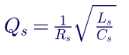
and the series tuning order of the branch is:

7.2 Detuning ratios for 60 Hz systems
| Reactor ratio p | Tuning order | Tuning frequency at 60 Hz | Tuning frequency at 50 Hz (reference only) | Typical use |
|---|---|---|---|---|
| 5.67% | 4.20 | 252 Hz | 210 Hz | Common in US practice for 5th-dominant systems; branch absorbs some 5th current |
| 7% | 3.78 | 227 Hz | 189 Hz | Conservative detuning for 5th and higher; less absorption |
| 14% | 2.67 | 160 Hz | 134 Hz | Systems with significant 3rd harmonic (single-phase loads, unbalanced loads) |
Using 50 Hz tuning frequencies in a US design is a common and costly error. A designer who looks up "7% equals 189 Hz" and compares it with 300 Hz for the 5th harmonic gets the right conclusion for the wrong reason; one who applies a 50 Hz table to select a ratio for a target frequency gets the wrong reactor.
7.3 Capacitor voltage rise
The series reactor raises the fundamental voltage across the capacitor:
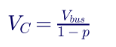
For a 480 V bus with 7% detuning, VC = 480 ÷ 0.93 = 516 V. Harmonic voltages add to this. Capacitors in detuned banks must therefore be rated above system voltage — typically 525 V or 600 V units on a 480 V system, and correspondingly higher ratings at medium voltage.
7.4 Effective kvar output
The output of a detuned step depends on the capacitor's rated voltage and the detuning ratio:

A 600 kvar, 525 V capacitor step with 7% detuning on a 480 V bus delivers about 600 × (480 ÷ 525)² ÷ 0.93 ≈ 539 kvar. Designers who specify detuned banks by nameplate capacitor kvar without this correction will under- or over-compensate.
7.5 The resonance that detuning creates
A detuned bank does not eliminate parallel resonance. It moves the combined network resonance below the branch tuning frequency. In Keentel's 13.8 kV model, the 7% detuned 9 Mvar bank produces a parallel resonance near the 3.1st harmonic. That is harmless if 3rd harmonic current is negligible — usually true on a balanced three-wire 13.8 kV bus with six-pulse drives. It can be harmful at 480 V or 208 V buses with large single-phase loads or unbalance, where 3rd harmonic current flows. In those cases a 14% ratio, tuning at 160 Hz, keeps the resonance below the 3rd.
7.6 What detuned reactors are not
Detuned reactors protect the capacitor bank and prevent it from creating a resonance at characteristic harmonics. They are not harmonic filters. A 7% detuned bank absorbs only a modest share of 5th harmonic current. If a facility must reduce harmonic current to meet IEEE 519 at the point of common coupling, a tuned filter or active harmonic filter is usually needed.
8. Tuned passive filters
8.1 Single-tuned filters
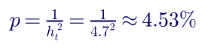
A single-tuned filter deliberately creates a low-impedance series path at a specific harmonic, slightly below it to allow for capacitor tolerance, temperature drift and aging. For the 5th harmonic, tuning near 4.7th is typical. The reactor ratio is:
8.2 Worked example: 9 Mvar, 13.8 kV 5th harmonic filter
| Quantity | Calculation | Result |
|---|---|---|
| Capacitor reactance | 13.8² ÷ 9 | 21.16 Ω |
| Reactor reactance at 60 Hz | 21.16 × 4.7% | 0.958 Ω |
| Reactor inductance | 0.958 ÷ (2π × 60) | 2.54 mH |
| Capacitor fundamental voltage | 13.8 ÷ (1 − 0.0453) | 14.45 kV line-to-line (rate capacitors accordingly) |
| Quality factor (typical) | XL at tuning ÷ R | 30 to 60 |
The filter still forms a parallel resonance with the source, now below 4.7th. The design must confirm that this resonance does not coincide with any harmonic present, including non-characteristic harmonics from unbalance and transformer inrush.
8.3 Filter duty and absorption
A tuned filter absorbs harmonic current not only from the plant's drives but from the entire utility system. A filter designed only for the plant's own harmonic load can be overloaded by background distortion. IEEE 1531 describes the design process, including background distortion, detuning, unbalance protection and ratings of each component.
8.4 Damped and high-pass filters
Second-order high-pass and C-type filters provide damping across a band rather than a single sharp notch. They are common at transmission and collector levels, where the resonant frequency may move with network configuration and a sharp notch could create new resonances. C-type filters avoid fundamental-frequency losses in the damping resistor by tuning an auxiliary branch to fundamental frequency.
9. Active harmonic filters and network impedance
Active harmonic filters (AHFs) inject harmonic currents in opposition to load harmonics, measured through current transformers. They are effective for variable loads and for multiple harmonic orders. However, they are not a substitute for understanding network impedance:
| Issue | Why it matters |
|---|---|
| Limited control bandwidth | AHFs compensate up to a maximum harmonic order, typically the 50th; resonances above that range are unaffected |
| Rating limits | At resonance, harmonic currents may exceed AHF capacity, causing the AHF to saturate and stop compensating effectively |
| CT location | Compensating load current does not address distortion imported from the supply or circulating between capacitors and the source |
| Interaction with capacitors | Capacitors downstream of AHF current measurement can create resonances the AHF cannot see or may amplify |
| Control stability | AHF controls interact with network impedance; in some cases they can excite resonances near their switching or control bandwidth |
| Switching-frequency emissions | AHFs and active front ends emit at 2 kHz to 20 kHz; cable capacitance and capacitors can resonate there |
An AHF should be specified after a frequency scan of the network, with its rating, CT location and control settings selected for the actual resonance conditions.
10. Equipment duty
10.1 Capacitor limits under IEEE 18
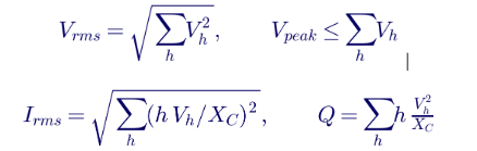
IEEE Std 18 specifies continuous operating limits for shunt power capacitors, including harmonic content:
| Quantity | IEEE 18 continuous limit |
|---|---|
| RMS voltage | 110% of rated |
| Crest (peak) voltage | 120% of rated √2 voltage |
| RMS current | 135% of nominal current at rated voltage and frequency |
| Reactive power | 135% of rated kvar |
Duty quantities are calculated by summing harmonic components:
10.2 Worked example: duty of the 9 Mvar bank in resonance
Using the harmonic voltages from Keentel's scan for the 9 Mvar case at nominal fundamental voltage:
| Quantity | Calculated value | IEEE 18 limit | Assessment |
|---|---|---|---|
| RMS voltage | 1.003 pu | 1.10 pu | Within limit |
| Peak voltage (arithmetic sum, worst case) | 1.10 pu | 1.20 pu | Within limit, small margin if fundamental voltage is high |
| RMS current | 1.075 pu | 1.35 pu | Within limit |
| Reactive power | 1.03 pu | 1.35 pu | Within limit |
This result is instructive. The capacitor bank itself is within its IEEE 18 ratings, yet the bus voltage THD of 7.7% exceeds the IEEE 519 limit of 5% for 13.8 kV buses. Equipment damage is not the only consequence of resonance; voltage quality for every load on the bus is. With operating voltage at 105% and a lighter load (less damping), the margins on peak voltage and current shrink rapidly. Capacitor fuses — sized with modest margin over fundamental current — and capacitor units with manufacturing tolerances or aging can fail long before the bank as a whole reaches its limits.
10.3 Transformers
Harmonic currents increase transformer eddy-current and stray losses, which rise roughly with the square of harmonic order. IEEE C57.110 provides the harmonic loss factor method for derating:
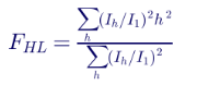
A transformer carrying amplified 5th and 7th harmonic currents in series resonance can overheat at a fundamental load well below nameplate.
10.4 Drives, UPS and electronic loads
Voltage distortion flattens or peaks the voltage waveform. Six-pulse drives charge their DC link from the voltage peaks; a peaked waveform raises DC bus voltage and can cause overvoltage trips, while a flattened waveform reduces it and can cause undervoltage trips under load. Distortion can also disturb zero-crossing detection in thyristor controls, synchronization of UPS and generator systems, and the operation of sensitive instrumentation.
10.5 Cables, motors and metering
Harmonic currents increase cable heating through skin and proximity effects. Negative-sequence harmonics (5th, 11th) create counter-rotating torque in motors, raising losses and vibration. Revenue meters and protective relays may respond differently to distorted waveforms, causing billing disputes or protection misoperation.
11. IEEE 519-2022 limits
IEEE 519-2022 sets harmonic limits at the point of common coupling (PCC) — the point where the utility serves multiple customers, or as agreed between the user and utility.
11.1 Voltage distortion limits
| Bus voltage at PCC | Individual harmonic | Voltage THD |
|---|---|---|
| 1 kV and below | 5.0% | 8.0% |
| Above 1 kV through 69 kV | 3.0% | 5.0% |
| Above 69 kV through 161 kV | 1.5% | 2.5% |
| Above 161 kV | 1.0% | 1.5% |
In US voltage classes: 480 V and 600 V buses fall in the first row; 4.16 kV, 13.8 kV, 34.5 kV and 69 kV in the second; 115 kV and 138 kV in the third; 230 kV, 345 kV, 500 kV and 765 kV in the fourth.
11.2 Current distortion limits (120 V through 69 kV)
| Isc/IL | h < 11 | 11 ≤ h < 17 | 17 ≤ h < 23 | 23 ≤ h < 35 | 35 ≤ h ≤ 50 | TDD |
|---|---|---|---|---|---|---|
| < 20 | 4.0% | 2.0% | 1.5% | 0.6% | 0.3% | 5.0% |
| 20 to < 50 | 7.0% | 3.5% | 2.5% | 1.0% | 0.5% | 8.0% |
| 50 to < 100 | 10.0% | 4.5% | 4.0% | 1.5% | 0.7% | 12.0% |
| 100 to < 1000 | 12.0% | 5.5% | 5.0% | 2.0% | 1.0% | 15.0% |
| > 1000 | 15.0% | 7.0% | 6.0% | 2.5% | 1.4% | 20.0% |
Even harmonics are limited to 25% of the odd harmonic limits. The 2022 edition also allows defined percentages of time above the limits (for example, statistical evaluation using very-short-time and short-time values) and provides adjustments for low-order harmonics in certain conditions. The current limits apply to the user's emissions; the voltage limits are the shared responsibility of user and utility.
11.3 Why resonance complicates compliance
IEEE 519 compliance is assessed at the PCC, but resonance inside a facility can cause problems that never violate PCC limits, and a utility-side resonance can cause PCC voltage limits to be exceeded even when every customer meets its current limits. Compliance and reliability are related but not the same question.
12. Credible operating configurations
Resonance studies must consider every credible configuration, not just the design case.
| Configuration change | Effect on resonance |
|---|---|
| Capacitor stages switched in or out | More capacitance lowers the resonance; automatic controllers sweep it through a range |
| Transformers paralleled or tie breakers closed | Lower source inductance raises the resonance; may move it from 5th to 7th |
| Transformers with different impedances in parallel | Changes both the resonance and the current sharing at harmonic frequencies |
| Utility source changes (alternate feed, upstream outage, generation changes) | Changes short-circuit capacity and moves the resonance |
| On-site generators running | Generator subtransient reactance changes source impedance |
| New MV cable runs | Adds distributed capacitance; long cables may create resonances on their own |
| Load level changes (night, weekend, process shutdown) | Reduces damping; peaks rise |
| New converter loads or retrofits | Adds harmonic sources; may remove resistive damping |
| Utility capacitor bank switching nearby | Changes background impedance and distortion |
13. A practical investigation and study workflow
- Collect data: one-line diagrams, transformer nameplates, cable lengths and types, capacitor banks and controls, drive and converter inventory, utility short-circuit data (maximum and minimum) and utility capacitor banks near the PCC.
- Measure: install power quality monitors at the PCC, main buses and suspected equipment, recording harmonic voltages and currents with phase angles over at least a week of representative operation. Use measurement methods consistent with IEEE 1159 and IEEE 519-2022.
- Build the harmonic model: frequency-dependent models of sources, transformers, cables, capacitors, motors, loads and harmonic sources in a harmonic analysis program.
- Run frequency scans: driving-point impedance at key buses and transfer impedances between buses for every credible configuration.
- Run harmonic load flows: calculate harmonic voltages and currents for each configuration with realistic harmonic spectra.
- Validate the model: compare calculated distortion with measurements for the configurations observed in the field. Adjust source impedance, load damping and harmonic spectra as needed.
- Check equipment duty: capacitors (IEEE 18), filters (IEEE 1531), transformers (IEEE C57.110), cables, drives and protective devices.
- Design mitigation: detuned or tuned banks, filters, AHFs, configuration limits or source changes.
- Verify after installation: measure again and confirm that distortion and duty match predictions.
13.1 Digital twins and EMT simulation
For complex systems — large data centers, inverter-based plants, facilities with many converters — frequency-domain models can be supplemented by electromagnetic transient (EMT) simulations. EMT models capture capacitor switching transients, transformer inrush, converter control behavior and nonlinear interactions that frequency-domain methods simplify. A validated model, kept current as the facility changes, becomes a digital twin that can screen future additions before they are installed.
14. Resonance in inverter-based plants and data centers
14.1 Solar, wind and storage collector systems
Utility-scale plants use long 34.5 kV collector cables, inverter step-up transformers, a main power transformer to 115 kV, 138 kV, 230 kV or 345 kV, and sometimes shunt capacitor banks or harmonic filters. Cable capacitance resonating with transformer inductance typically produces resonances in the range of several hundred hertz to a few kilohertz. Background harmonic distortion from the transmission system can be amplified into the plant, and inverter emissions can be amplified out to the POI. Transmission providers increasingly require harmonic studies demonstrating IEEE 519 compliance at the POI.
14.2 Data centers
Data centers combine large UPS and server power supply loads, MV cable networks within the campus, power factor correction (sometimes integrated in UPS systems), on-site generators, and increasingly BESS and on-site generation. Modern UPS and power supplies with active front ends produce low low-order harmonics but emit near their switching frequencies. Generator operation raises source impedance dramatically compared with utility supply, moving resonances lower and increasing distortion during generator operation — a configuration that must be studied separately.
14.3 EV charging hubs
DC fast chargers aggregate tens of megawatts of converter load at a single service. Charger designs vary, and the combination of chargers from different vendors, service transformers and any site capacitors or storage converters creates resonances that must be studied as the hub grows.
14A. Capacitor switching, inrush and resonance
Resonance is a steady-state frequency-domain concept, but the same inductance and capacitance also govern switching transients. When a capacitor bank is energized, the network rings at its natural frequency — which is the same parallel resonant frequency identified in a frequency scan. Two effects deserve attention.
Magnification of switching transients
When a utility switches a large capacitor bank on its system, an oscillatory transient at a few hundred hertz propagates down the feeder. If a customer's low-voltage capacitor bank and service transformer form a series circuit tuned near that transient frequency, the transient voltage at the customer bus can be magnified to two to four times its normal peak. Drives with diode front ends are especially vulnerable: the DC link capacitor charges through the surge and trips the drive on DC overvoltage. The classic remedy is to add input reactance (line reactors or DC chokes) to drives, convert the customer bank to a detuned bank, or ask the utility to use synchronous closing or pre-insertion devices on its bank.
Back-to-back switching inrush
When one capacitor stage is energized next to stages already in service, the inrush current is limited only by the small inductance between them. The peak inrush current and frequency for back-to-back switching are approximately:

where Ceq is the series combination of the switched and energized capacitances and Leq is the inductance between them. Inrush frequencies of several kilohertz and peaks of many times rated current are common. IEEE C37.012 and IEEE 1036 provide guidance on limiting reactors and switching device capability. A detuned reactor in each step also limits back-to-back inrush — a secondary benefit that is often overlooked.
Transformer energization and the 2nd harmonic
Transformer inrush current is rich in the 2nd harmonic and also contains odd harmonics. If a network has a parallel resonance near the 2nd or 3rd harmonic — as happens with heavily detuned banks or very large capacitance relative to source strength — energizing a transformer can excite sustained resonant overvoltage that decays slowly. This temporary overvoltage can stress surge arresters and delay relay restraint. EMT studies are the appropriate tool when a resonance below the 4th harmonic is identified at a bus where large transformers are energized.
14B. Worked example: should the plant buy an active filter or a detuned bank?
A 480 V plant has 900 kW of six-pulse drive load and a 2,000 kVA, 5.75% transformer. It wants both power factor correction (about 600 kvar) and compliance with an IEEE 519 TDD limit of 8% at its 13.8 kV PCC, where ISC/IL is about 35.
| Option | Harmonic result | Resonance risk | Approximate considerations |
|---|---|---|---|
| Plain 600 kvar automatic bank | Current TDD unchanged or worse; resonance near the 7.6th with all steps in | High: steps sweep the resonance across the 7th | Lowest cost, highest risk |
| 600 kvar bank, 7% detuned | TDD reduced modestly by partial 5th absorption | Low at characteristic harmonics; new resonance near the 3rd | Moderate cost; PF goal met; may not meet TDD alone |
| Active harmonic filter sized for drive harmonics, plus 7% detuned bank | TDD reduced below the limit | Low, provided the AHF CTs are located upstream of the detuned bank and the AHF is not asked to compensate bank currents | Higher cost; meets both goals |
| Drives replaced or retrofitted with active front ends | TDD very low at low orders | Check emissions near switching frequency | Highest cost; long-term best where drives are due for replacement |
The engineering point is that the decision depends on the resonance analysis. A plain bank — the cheapest line in the table — is the one most likely to create the problem the plant is trying to avoid. Keentel's practice is to select the option by modeling all four alternatives in every credible configuration, then confirming the chosen option with measurements after installation.
15. Common misconceptions corrected
| Misconception | Engineering reality |
|---|---|
| "Harmonics come from the equipment, so fix the equipment." | The network determines how harmonic currents become harmonic voltages and where currents flow. Fixing the source without studying the network can leave the resonance in place. |
| "Capacitors absorb harmonics, so they help." | Unfiltered capacitors often create resonances that amplify harmonics. Only tuned branches absorb harmonics in a controlled way. |
| "Detuned reactors are harmonic filters." | Detuned reactors protect the capacitor and avoid resonance at characteristic harmonics; they absorb relatively little harmonic current. |
| "An active filter makes a network study unnecessary." | AHF rating, bandwidth and CT location must suit the actual network impedance and resonances. |
| "If we met IEEE 519 at commissioning, we are done." | Configuration changes, new loads, utility changes and capacitor switching can create new resonances later. |
| "The 50 Hz detuning table applies everywhere." | US systems are 60 Hz; tuning frequencies are 20% higher for the same ratio. |
| "A meter showing high harmonic current at a facility proves the facility is the source." | Series resonance can make a facility draw large harmonic currents from upstream distortion. Phase angle analysis is needed. |
| "Resonance is a fault." | Resonance is a network property. It becomes a problem only when it coincides with harmonic sources and insufficient damping. |
16. Key takeaways
- The network matters as much as the harmonic source. Vh = Ih × Zh, and Zh is set by the network.
- Parallel resonance amplifies voltage; series resonance amplifies current. Both can occur in the same facility.
- Estimate first, then scan. hr = √(MVAsc ÷ Mvar) gives a fast warning; frequency scans and harmonic load flows confirm.
- Study every credible configuration. Capacitor stages, transformer paralleling, source changes and load levels all move the resonance.
- Use 60 Hz numbers. ft = 60 ÷ √p for detuned and tuned banks in the US.
- Check equipment duty and voltage quality. IEEE 18, IEEE 1531, IEEE C57.110 and IEEE 519-2022 each address a different part of the problem.
- Verify in the field. Measurement before and after mitigation closes the loop.
17. How Keentel Engineering helps
Keentel Engineering performs power quality and harmonic studies for industrial plants, data centers, water and wastewater utilities, EV charging hubs, solar, wind and storage plants and electric utilities, from 480 V to 765 kV.
| Stage | Keentel scope | Outcome |
|---|---|---|
| Power quality investigation | Measurement planning, monitor installation, data analysis and root cause | Clear diagnosis of the source and the network's role |
| Harmonic modeling | Frequency-dependent models of sources, transformers, cables, capacitors and loads | Accurate, validated harmonic model |
| Frequency scans and harmonic load flow | All credible configurations, including capacitor stages, transformer ties and generator operation | Identification of resonances before they cause damage |
| Equipment duty assessment | Capacitors (IEEE 18), filters (IEEE 1531), transformers (IEEE C57.110), cables and drives | Confirmation that equipment is properly rated |
| Mitigation design | Detuned banks, tuned and damped filters, AHF specification, configuration limits | Cost-effective solutions that suit the network |
| IEEE 519 compliance | PCC assessment and documentation for utilities and transmission providers | Compliance with supporting evidence |
| Inverter-based plant harmonics | Collector system and POI harmonic studies, EMT studies | Interconnection approval and reliable operation |
| Verification | Post-installation measurement and model updates | Proof that mitigation works |
Why clients choose Keentel Engineering
- System-level thinking: we study the network, not only the equipment.
- From measurement to design: field data, models and engineered solutions under one team.
- Utility and industrial experience: practical knowledge of utility requirements and facility operations.
- Inverter-based resource expertise: harmonic and EMT studies for solar, wind and storage interconnections.
- Licensed professional engineering: a Florida-registered firm with offices in Tampa, Austin, Sacramento and Baltimore, supporting projects nationwide.
Capacitor fuses operating, transformers running hot or drives tripping without explanation? Talk to Keentel Engineering at (813) 389-7871, contact@keentelengineering.com, or book a 15-minute scoping call at calendly.com/keentel-engineering/15min.
Part C — Case Studies
The following are illustrative scenarios based on conditions typical of US facilities and interconnections. They show how Keentel Engineering approaches harmonic resonance problems; site details are generalized and figures are rounded.
Case Study 1 — 480 V food processing plant: capacitor fuses and drive trips
Situation. A food processing plant supplied by a 2,000 kVA, 13.8 kV to 480 V transformer installs a 1,200 kvar automatic power factor correction bank in four 300 kvar steps. Within weeks, capacitor fuses operate repeatedly, the transformer runs hot, and several conveyor and pump drives trip on DC bus overvoltage, usually during evening shifts when process heating is off.
Analysis. Keentel installs power quality monitors on the main bus and the capacitor bank. With all four steps in service, 5th harmonic voltage reaches 9% and capacitor current reaches 140% of rated during light-load periods. Hand calculation and a frequency scan show the parallel resonance moving from the 10.8th harmonic with one step to about the 5.4th with four steps — and closer still when the utility source impedance is included. Evening loss of resistive heating load reduces damping and sharpens the peak.
Engineered solution. Keentel specifies replacement of the bank with a 7% detuned automatic bank using 525 V capacitors, sized for an effective 1,100 kvar after accounting for voltage rise and detuning. The design confirms that the new network resonance near the 3rd harmonic does not coincide with significant 3rd harmonic current, which measurements show to be small on the three-wire 480 V system.
Outcome. Voltage THD falls below 4%, capacitor fuse operations stop, drive trips cease, and the plant retains its power factor improvement.
Case Study 2 — 13.8 kV water treatment plant: the second transformer
Situation. A water treatment plant has two 13.8 kV buses, each fed by a 115 kV to 13.8 kV transformer, with a normally open tie breaker. Large pump drives and a 6 Mvar capacitor bank are on Bus A. During a planned maintenance outage, operators close the tie and run both buses from one transformer, then later parallel both transformers. Pump drives on Bus B begin tripping, and power quality alarms report high 7th harmonic distortion.
Analysis. Keentel builds a harmonic model for every credible configuration: buses split, tie closed with one transformer, and tie closed with both transformers paralleled. With buses split, Bus A resonance is near the 6.5th harmonic — high distortion but within limits because of load damping. Paralleling the transformers lowers source impedance and moves the resonance to about the 7.4th, while the tie adds Bus B's drives as additional 7th harmonic sources. Measured 7th harmonic voltage exceeds 5%.
Engineered solution. Keentel recommends converting the 6 Mvar bank to a 5th harmonic tuned filter at the 4.7th harmonic, with a reactor and capacitors rated for background distortion and both configurations, and develops an operating procedure for tie operation until the filter is installed.
Outcome. Distortion remains below IEEE 519 limits in all configurations, the plant can use its tie breaker flexibly, and maintenance outages no longer cause drive trips.
Case Study 3 — 200 MW solar plant at 138 kV: amplified background distortion
Situation. A 200 MW solar plant with a 34.5 kV collector system connects to a 138 kV substation. After the utility installs a new 138 kV capacitor bank at a nearby substation, the plant's POI meter shows 13th harmonic voltage above the IEEE 519 individual limit of 1.5% for that voltage class, and the transmission provider asks the plant to investigate.
Analysis. Keentel's measurements show 13th harmonic current flowing into the plant from the 138 kV system, not out of it. A frequency scan of the plant and surrounding network reveals a parallel resonance near the 13th harmonic formed by the collector cable capacitance, the main power transformer and the new utility capacitor bank's effect on the system impedance. The plant's inverters are minor 13th harmonic sources; the resonance is amplifying existing background distortion.
Engineered solution. Keentel presents the analysis to the transmission provider with measured harmonic power flow direction and the frequency scan. The solution combines a damped high-pass filter at the plant's 34.5 kV bus, sized for background distortion, and an adjustment to the inverters' harmonic damping settings recommended by the inverter vendor.
Outcome. 13th harmonic voltage at the POI falls below 1%, the transmission provider accepts the study, and the plant avoids curtailment while the utility updates its own capacitor bank switching practice.
Part D — Technical FAQ: Harmonic Resonance
A condition where the network's inductance and capacitance produce either very high impedance (parallel resonance) or very low impedance (series resonance) at a harmonic frequency, amplifying harmonic voltage or current.
Parallel resonance raises the impedance seen by a harmonic current source and amplifies harmonic voltage. Series resonance lowers the impedance of a specific path and amplifies harmonic current driven by an existing harmonic voltage.
Use hr = √(MVAsc ÷ Mvar) at the capacitor bus, or hr ≈ √(kVA ÷ (kvar × Z)) for a low-voltage bus fed by a transformer from a strong source. Multiply by 60 Hz to get the frequency.
The 5th is usually the largest harmonic from six-pulse drives and rectifiers. A resonance near it multiplies the most significant harmonic current into a large voltage or current.
A measure of how sharp and high the resonance peak is. For a parallel resonance Q = R√(C/L); the impedance at resonance is about Q times the reactance of each element. Higher damping gives lower Q.
Resistive loads provide damping. When they are off — at night, weekends or during shutdowns — Q rises and the resonance peak becomes larger.
Yes. A transformer and capacitor bank can form a series resonance that draws amplified harmonic current from distortion already on the utility system.
A capacitor bank with a series reactor in each step, tuned below the lowest significant harmonic so the step is inductive at characteristic harmonics and cannot resonate with the source at those frequencies.
f = 60 ÷ √0.07 ≈ 227 Hz, or the 3.78th harmonic. The often-quoted 189 Hz applies only to 50 Hz systems.
The series reactor raises the fundamental capacitor voltage by 1 ÷ (1 − p). With 7% detuning at 480 V, the capacitor sees about 516 V before harmonics are added.
No. It creates a network resonance below its tuning frequency. That resonance must not coincide with harmonics present, such as the 3rd harmonic in systems with single-phase loads.
When significant 3rd harmonic current is present, for example on 208 V or 480 V systems with large single-phase loads or unbalance. A 14% ratio tunes to 160 Hz, below the 180 Hz 3rd harmonic.
A detuned bank is tuned well below the harmonics to avoid resonance and absorbs little harmonic current. A tuned filter is tuned close to a harmonic, typically the 4.7th for the 5th, to absorb that harmonic.
Their low impedance at the tuned frequency attracts harmonic current from every source connected to the network, including the utility. Filters must be rated for background distortion.
An AHF can reduce harmonic currents from loads it measures, but its rating, control bandwidth and CT location limit its effectiveness. It should be specified after a network frequency scan.
For buses above 1 kV through 69 kV, individual harmonics must be no more than 3% and voltage THD no more than 5%, evaluated statistically at the point of common coupling.
110% rms voltage, 120% peak voltage, 135% rms current and 135% reactive power, including harmonic components.
They reduce source impedance and raise the resonant frequency, which can move resonance from one harmonic to another — for example from near the 5th to near the 7th.
Power quality monitors for measurement, harmonic analysis programs for frequency scans and harmonic load flows, and EMT simulation for switching transients and converter interactions.
Focusing only on the harmonic source and the design configuration, without frequency scans of every credible configuration and field verification.
References and Further Reading
Links were current at publication (October 2026).
- IEEE Std 519-2022, Standard for Harmonic Control in Electric Power Systems. IEEE.
- IEEE Std 18-2012, Standard for Shunt Power Capacitors. IEEE.
- IEEE Std 1531-2020, Guide for the Application and Specification of Harmonic Filters. IEEE.
- IEEE Std 1036-2020, Guide for the Application of Shunt Power Capacitors. IEEE.
- IEEE Std C57.110-2018, Recommended Practice for Establishing Liquid-Immersed and Dry-Type Power and Distribution Transformer Capability When Supplying Nonsinusoidal Load Currents. IEEE.
- IEEE Std 1159-2019, Recommended Practice for Monitoring Electric Power Quality. IEEE.
- IEEE Std 399, Recommended Practice for Industrial and Commercial Power Systems Analysis (Brown Book), harmonic analysis chapter. IEEE.
- R. C. Dugan, M. F. McGranaghan, S. Santoso and H. W. Beaty, Electrical Power Systems Quality, McGraw-Hill.
- J. Arrillaga and N. R. Watson, Power System Harmonics, Wiley.
Disclaimer
This article is general technical information for educational purposes. It is not engineering advice for any specific project and does not create a professional relationship. The frequency scan results come from Keentel Engineering's simplified illustrative model; actual resonances and distortion depend on site-specific source impedance, equipment, loads and operating configurations and must be verified by project-specific study and measurement. Designs must follow current IEEE standards, the NEC, utility and transmission provider requirements and project-specific engineering analysis, sealed by a licensed professional engineer where required.
Case studies are illustrative scenarios based on typical project conditions, not records of specific client projects. Figures are rounded and indicative.
IEEE and other names are the property of their respective owners. Keentel Engineering is not affiliated with or endorsed by these organizations or any equipment vendor.
| Office | Address | Phone |
|---|---|---|
| Head Office — Tampa | 400 N Ashley Dr STE #2600, Tampa FL 33602 | (813) 389-7871 |
| Austin | 5900 Balcones Drive STE 100, Austin TX 78731 | (512) 591-0752 |
| Sacramento | 1401 21st St Ste R, Sacramento CA 95811 | (916) 913-4524 |
| Baltimore | 306 W Redwood St STE 200, Baltimore MD 21201 | (410) 225-2181 |

About the Author:
Sandip "Sonny" R. Patel, P.E.
IEEE Senior Member · Founder & CEO, Keentel Engineering
In 1995, Sonny Patel earned his Electrical Engineering degree from the University of Illinois. But degrees don't build legacies — action does.
For three decades, he has worked the power industry from every side of the table: 16 years as a utility engineer at Exelon/Commonwealth Edison; generation leadership across hydroelectric, industrial steam turbine, and a 9 GW renewable fleet; NERC Regional Entity Senior Compliance Engineer and Audit Team Lead, auditing some of the nation's largest utilities; and testing and commissioning lead on equipment up to 765 kV — the very top of the North American grid.Utility. Generator. Regulator. Consultant. Few engineers have seen all four seats. Fewer still have sat in them.
His experience spans nuclear, hydro, conventional generation, renewables, oil and gas, mining — and today's data centers, where he is authoring a three-book series on data center design. He is a Licensed Professional Engineer in six states and a Licensed Electrical Contractor in Florida (Unlimited EC) — he doesn't just design the work; he's qualified to stand behind its execution.Today, as Founder and CEO of Keentel Engineering, Sonny leads a nationwide team of engineers delivering substation design, power system studies, NERC compliance, and commissioning — done right, coast to coast.Three decades. Every side of the table. One standard: accountable engineering.
Services

Let's Discuss Your Project
Let's book a call to discuss your electrical engineering project that we can help you with.
About the Author:
Sandip "Sonny" R. Patel, P.E.
IEEE Senior Member · Founder & CEO, Keentel Engineering
In 1995, Sonny Patel earned his Electrical Engineering degree from the University of Illinois. But degrees don't build legacies — action does.
For three decades, he has worked the power industry from every side of the table: 16 years as a utility engineer at Exelon/Commonwealth Edison; generation leadership across hydroelectric, industrial steam turbine, and a 9 GW renewable fleet; NERC Regional Entity Senior Compliance Engineer and Audit Team Lead, auditing some of the nation's largest utilities; and testing and commissioning lead on equipment up to 765 kV — the very top of the North American grid.
Utility. Generator. Regulator. Consultant. Few engineers have seen all four seats. Fewer still have sat in them.
His experience spans nuclear, hydro, conventional generation, renewables, oil and gas, mining — and today's data centers, where he is authoring a three-book series on data center design. He is a Licensed Professional Engineer in six states and a Licensed Electrical Contractor in Florida (Unlimited EC) — he doesn't just design the work; he's qualified to stand behind its execution.
Today, as Founder and CEO of Keentel Engineering, Sonny leads a nationwide team of engineers delivering substation design, power system studies, NERC compliance, and commissioning — done right, coast to coast.Three decades. Every side of the table. One standard: accountable engineering.
Leave a Comment
Thank you for contacting us.
We will get back to you as soon as possible.
We will get back to you as soon as possible.
Oops, there was an error sending your message.
Please try again later.
Please try again later.
Related Posts
By SANDIP R PATEL
•
October 21, 2026
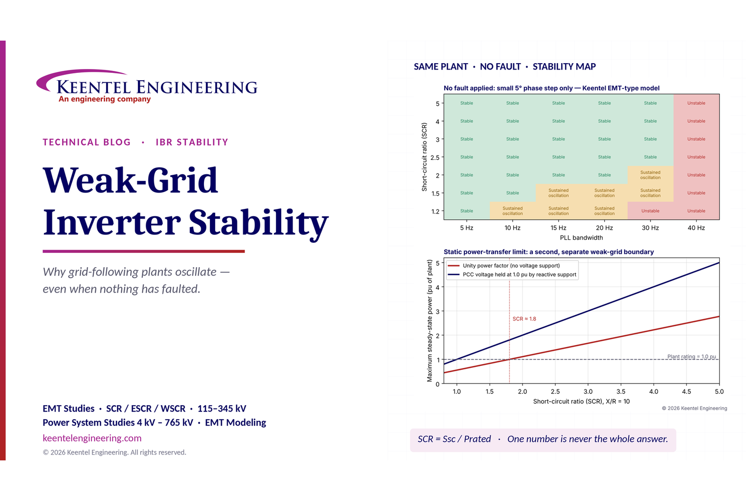
Learn why grid-following inverters become unstable without grid faults. Explore SCR, PLL interactions, EMT studies, grid strength, and mitigation.
By SANDIP R PATEL
•
October 20, 2026
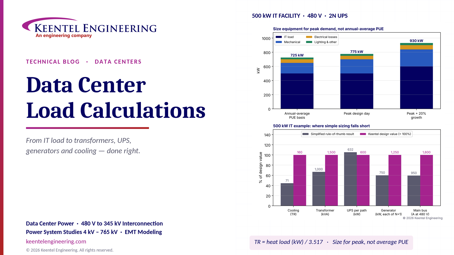
Learn data center electrical load calculations, including IT demand, PUE, UPS and generator sizing, cooling loads, redundancy, and worked US examples.
By SANDIP R PATEL
•
October 20, 2026
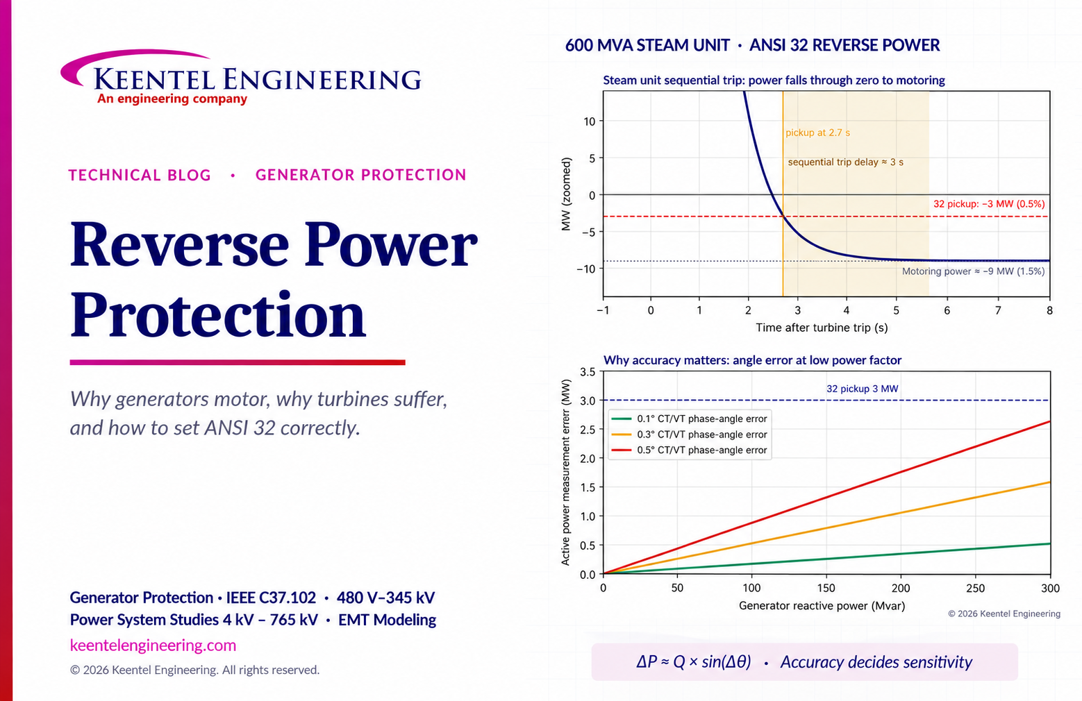
Learn reverse power protection (ANSI 32), generator motoring, relay pickup settings, time delays, sequential tripping and testing for US power plants.
Copy
By Team 2 Dexora
•
October 20, 2026
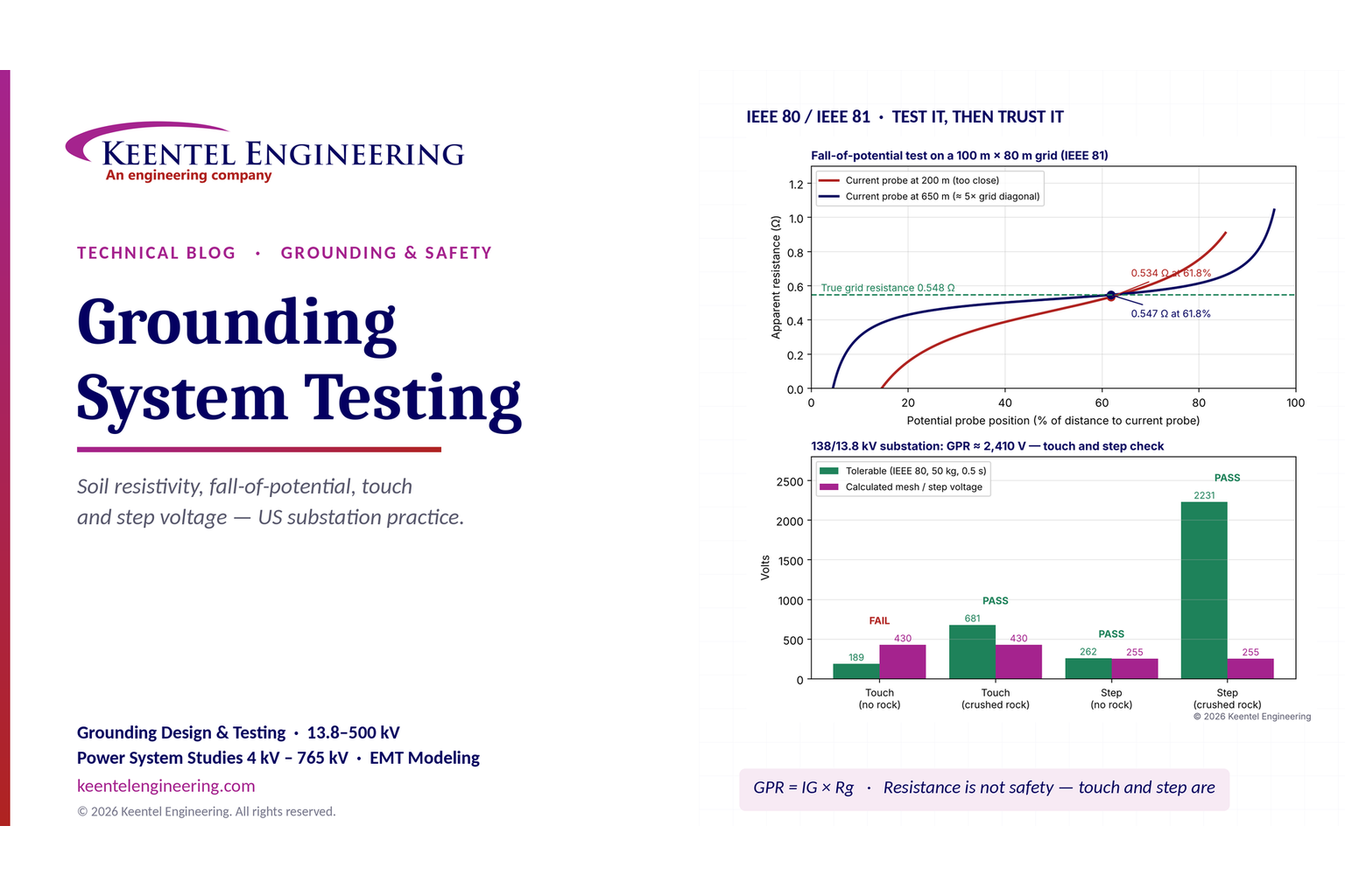
Explore grounding system testing with Keentel Engineering. Learn IEEE 80/81 methods, soil resistivity, ground resistance, and touch and step voltage safety.
By SANDIP R PATEL
•
October 13, 2026
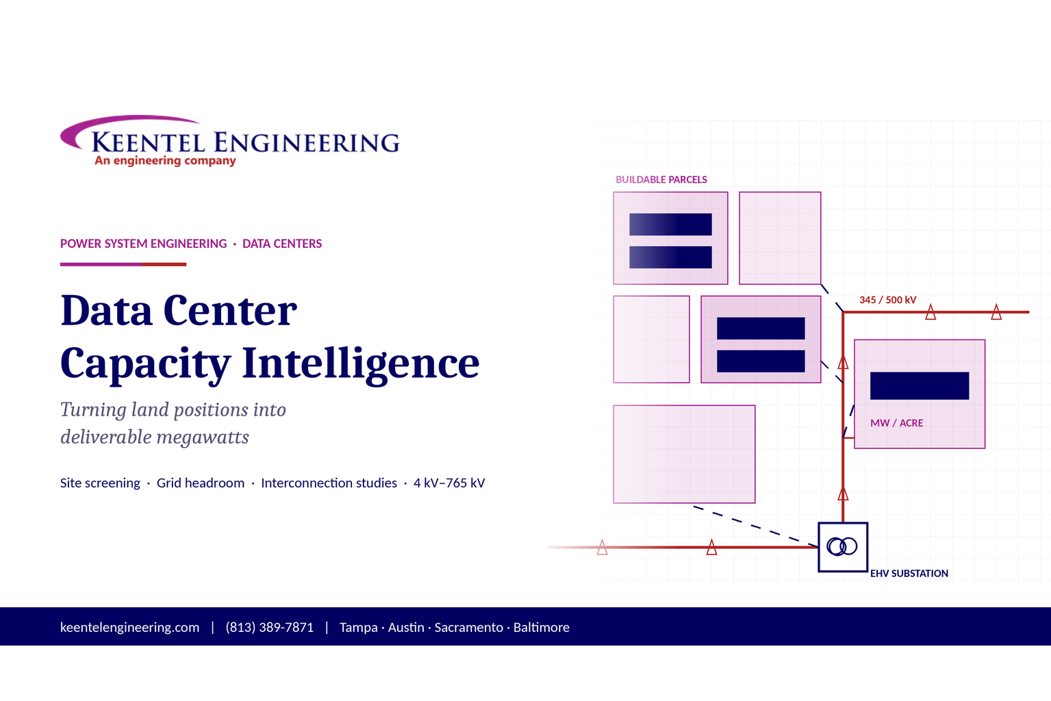
Plan data center capacity with land screening, MW-per-acre estimates, grid power availability and interconnection feasibility studies from Keentel Engineering.
By SANDIP R PATEL
•
October 11, 2026
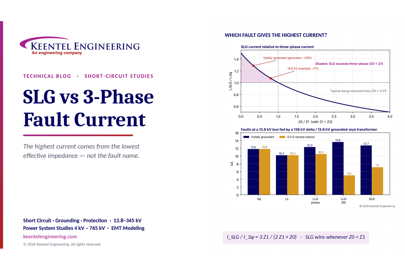
Learn which fault produces the highest current at a bus, why SLG faults can exceed three-phase faults, and how symmetrical components determine fault duty.
By SANDIP R PATEL
•
October 11, 2026
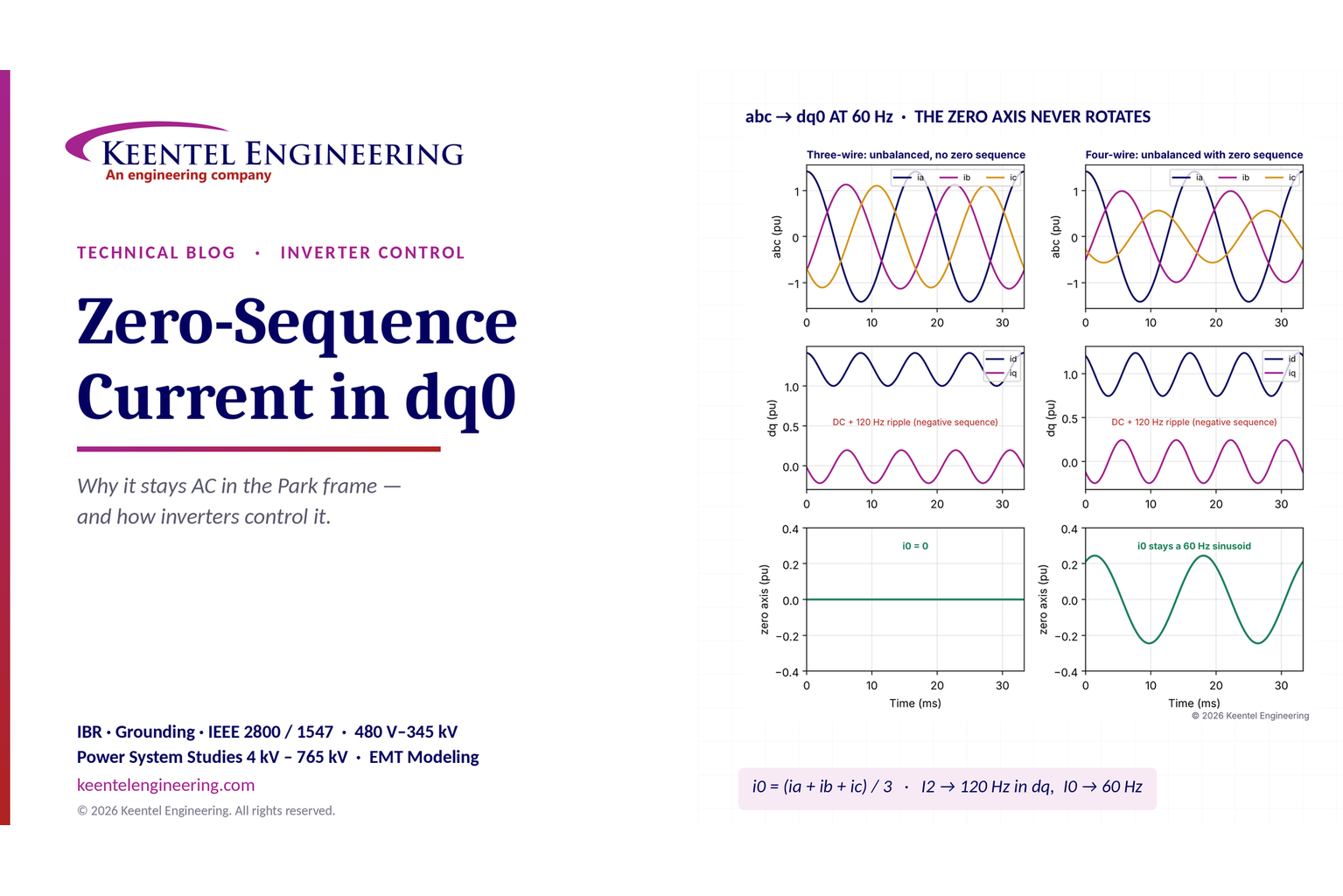
Learn why zero-sequence current pulsates in the dq0 frame, how Park's transformation works, and how inverter controls handle unbalance and ground faults.
By SANDIP R PATEL
•
October 11, 2026
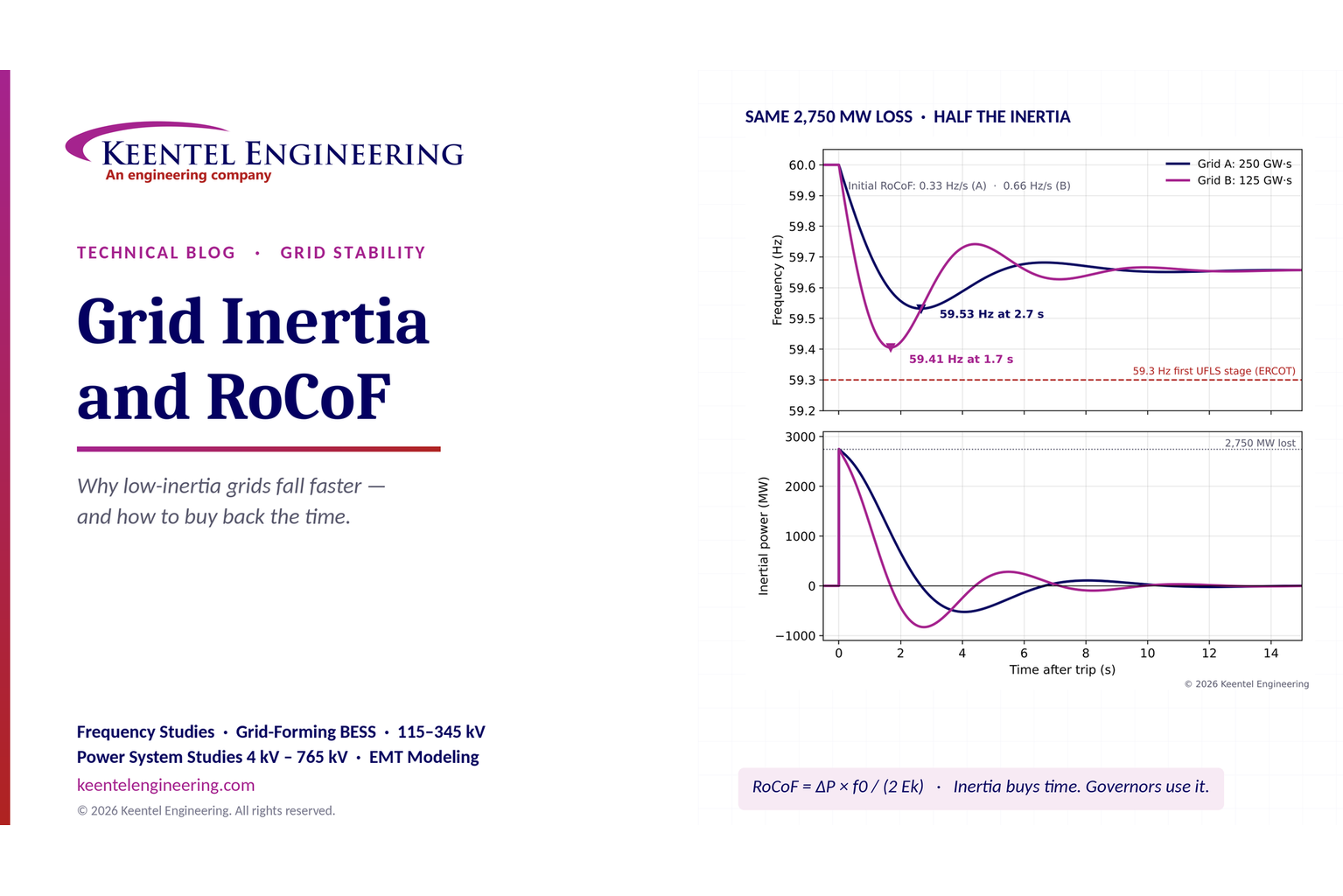
Explore grid inertia, RoCoF and frequency response, with swing equation calculations, frequency nadir analysis and US power system simulation examples.
By SANDIP R PATEL
•
October 11, 2026
Learn transient stability analysis, swing equation, equal-area criterion and critical clearing time with a 345 kV worked example and NERC TPL-001 guidance.