Part A — The SSSC at a Glance
A transmission corridor does not always need new structures to carry more power. Very often the existing network has capacity in aggregate, but power divides across parallel paths according to their impedances rather than their ratings. One line reaches its thermal limit while a neighbor carries half its rating, and the whole interface is limited by the first element to overload. Controlling how power divides between paths can release that stranded capacity.
The Static Synchronous Series Compensator (SSSC) is a power-electronic Flexible AC Transmission System (FACTS) device that does exactly this. It uses a voltage-source converter (VSC) and a series coupling transformer to inject a controllable 60 Hz voltage in series with a line. When the injected voltage is held in quadrature (90°) with the line current, the SSSC behaves like a variable series capacitor or a variable series reactor, raising or lowering the flow on that line. Because the injection is synthesized by a converter rather than produced by a physical capacitor, the SSSC has no 60 Hz resonance with the line inductance, responds within cycles, and can be modulated to damp power oscillations .
This guide explains how the SSSC works, how to calculate what it does to a real US transmission line, how it compares with the other FACTS devices and with phase-shifting transformers, and what owners must address in planning, prot NERC compliance before installing one.
The SSSC in one table
| Item | What it is | Engineering note |
|---|---|---|
| Function | Series voltage injection to control line power flow | Injected voltage nominally in quadrature with line current |
| Main components | Series coupling transformer (or transformerless modules), VSC (two-level, three-level or modular multilevel), DC capacitor, bypass breaker, thyristor or electronic bypass, MOV, controls | A true SSSC has a DC capacitor only — no energy source |
| Operating modes | Capacitive (increase flow) or inductive (decrease or reverse flow) | Range set by injected-voltage rating and line current |
| Control modes | Constant voltage, constant reactance, constant power, power oscillation damping (POD) | Constant voltage is the simplest; constant reactance mimics a series capacitor |
| Rating | S = 3·Vq·I (MVA) | Typically a few percent to about 15% of the line's thermal MVA |
| Response | Within about one to two cycles for the converter; seconds for supervisory flow control | Fast enough for transient stability support and POD |
| Resonance | None at 60 Hz; no inherent subsynchronous resonance (SSR) driver | Controls must still be checked for subsynchronous control interaction |
| Typical US voltages | 69, 115, 138, 230 and 345 kV lines; centralized units at 345 kV, modular units at 69–230 kV | Modular units hang on the line or sit in a small yard |
What Keentel's analysis shows
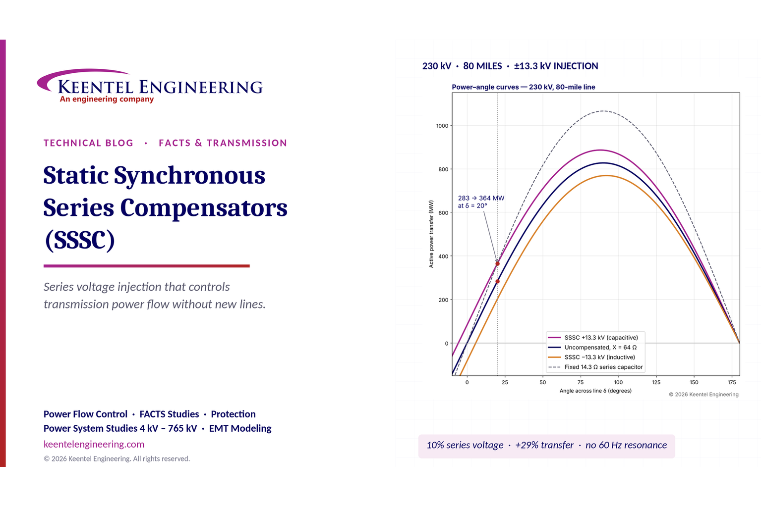
Keentel Engineering modeled an 80-mile, 230 kV line with a series reactance of 64 Ω (0.121 pu on 100 MVA), equal end voltages and a 20° angle across the line. An SSSC injects 13.3 kV per phase — about 10% of the line-to-neutral voltage.
| Quantity | Without SSSC | With SSSC (13.3 kV capacitive) |
|---|---|---|
| Active power transfer | 283 MW | 364 MW (+29%) |
| Line current | 721 A | 928 A |
| Equivalent series compensation at this load | — | 14.3 Ω (22% of line reactance) |
| Equivalent compensation at a 5° angle (light load) | — | 34.2 Ω (53%) — the same voltage looks like a larger capacitor at low current |
| SSSC loading at this operating point | — | 37 MVA (48 MVA at 1,200 A rated current) |
| Inductive injection that would reverse the flow at 20° | — | 46.1 kV per phase |
A second example shows congestion relief on two parallel 138 kV paths carrying a 300 MW interface transfer. Path A (20 Ω) carries 191 MW against a 170 MW rating; Path B (35 Ω) carries 109 MW. Adding 6.8 Ω of inductive SSSC reactance on Path A — a 4.8 kV per phase injection, about 10 MVA — pushes Path A down to its 170 MW rating and moves 21 MW onto Path B without any new line.

Figure 1. Keentel's illustrative SSSC analysis. Left: power–angle curves for the 230 kV, 80-mile line without compensation and with ±13.3 kV SSSC injection. Capacitive injection lifts the curve and produces flow even at zero angle; inductive injection lowers it and can reverse it. Right: flow on two parallel 138 kV paths as SSSC reactance is added to Path A, showing the 170 MW limit restored with about 6.8 Ω of inductive compensation.
Five lessons
Engineering review of common statements about the SSSC
| Statement often made | Keentel's check |
|---|---|
| "The SSSC injects a controllable AC voltage in series with the line through a coupling transformer." | Correct. Some modern designs are transformerless modular units that insert directly in the phase conductor; the principle is the same. |
| "The SSSC is fed by a DC source." | Oversimplified. A conventional SSSC has only a DC capacitor. In steady state it absorbs a small amount of real power from the line to cover losses and keep the capacitor charged. A real energy source or storage on the DC bus would let it exchange active power, but that is a different (and rarer) device. |
| "Line impedance" drawn as resistors | Misleading. Transmission lines are predominantly inductive. X/R is roughly 8–12 at 138–230 kV and 10–20 at 345 kV with bundled conductors. That is why reactive series injection controls flow so effectively. |
| "By controlling the magnitude and phase of the injected voltage, the SSSC can emulate capacitive or inductive series compensation." | Correct, with a nuance: in constant-voltage mode the emulated reactance is Vq/I and changes with load. In constant-reactance mode the controls scale Vq with current to mimic a fixed capacitor or reactor. |
| "It can increase power transfer capability." | Correct within limits. It raises the transfer on the compensated path and can raise interface limits, but voltage, stability and the thermal limits of other elements still apply. |
| "It helps damp power oscillations." | True only with a power oscillation damping (POD) controller, a suitable input signal and tuning verified by small-signal and EMT studies. |
| "A TCSC controls reactance; an SSSC controls voltage." | Correct but incomplete. A TCSC contains a physical capacitor, so it has resonance, SSR considerations and a limited vernier range. An SSSC has no 60 Hz resonance, can operate inductively or capacitively symmetrically, and can reverse flow — but it cannot inject when line current is near zero unless it has an independent DC supply. |
Part B — Static Synchronous Series Compensators in Technical Depth
1. Why power flow control matters again
1.1 Networks are meshed; ratings are not
In a meshed AC network, power divides among parallel paths in inverse proportion to their series reactances. The operator cannot direct it to the path with the most spare capacity. When one line reaches its thermal rating, the transfer across the whole interface is capped, even if the parallel paths are lightly loaded. Planners call this a loop flow or parallel flow problem, and it is one of the most common causes of congestion on US transmission systems.
Three trends have made the problem sharper:
1.2 The regulatory push toward advanced transmission technologies
Federal policy now asks transmission providers to consider power flow control alongside new construction.
The SSSC is one of the main "advanced power flow control" technologies these orders contemplate. Owners who can show credible engineering of SSSC alternatives are better placed in both planning and interconnection processes.
1.3 Where the SSSC sits in the FACTS family
FACTS devices fall into three groups: shunt devices that control voltage, series devices that control flow, and combined devices that do both.
| Device | Connection | Principle | Main purpose | Real power exchange | Resonance risk |
|---|---|---|---|---|---|
| Mechanically switched capacitor / reactor | Shunt | Switched passive element | Steady-state voltage | No | Harmonic resonance with the network |
| Static VAR compensator (SVC) | Shunt | Thyristor-controlled reactor plus thyristor-switched or fixed capacitors | Fast voltage control | No | Harmonic filters needed |
| STATCOM | Shunt | VSC behind a reactance | Fast voltage control, reactive current at low voltage | Only with storage | None at 60 Hz |
| Fixed series capacitor (FSC) | Series | Capacitor bank in the line, with MOV and bypass | Raise transfer and stability limits | No | Subsynchronous resonance with turbine-generators |
| Thyristor-controlled series capacitor (TCSC) | Series | Capacitor in parallel with a thyristor-controlled reactor | Variable compensation, SSR mitigation, damping | No | Internal parallel resonance; SSR must be studied |
| Static synchronous series compensator (SSSC) | Series | VSC injecting a series voltage | Flow control, damping | Only with storage or a shunt link | None at 60 Hz |
| Phase-shifting transformer (PST) | Series and shunt windings | Injects a voltage in quadrature with the bus voltage | Flow control, including reversal | Exchanges with the shunt winding | None |
| Unified power flow controller (UPFC) | Series plus shunt VSC sharing a DC bus | SSSC plus STATCOM back-to-back | Full control of P, Q and voltage | Yes, via the shunt converter | None |
| Interline power flow controller (IPFC) | Two or more series VSCs on different lines sharing a DC bus | SSSCs exchanging power between lines | Balance flows between lines | Between lines | None |
The key distinction between the SSSC and the phase-shifting transformer is the reference of the injected voltage. A PST injects a voltage in quadrature with the bus voltage, which shifts the angle and requires real power drawn from the shunt winding. An SSSC injects a voltage in quadrature with the line current, which changes the apparent reactance and needs no real power except for losses.
2. Inside the SSSC
2.1 Topology
A conventional, centralized SSSC has five main parts:
A newer class of modular SSSC uses many small, single-phase, transformerless converter modules mounted on the line structures or in a compact yard. Each module injects a fraction of a kilovolt; the modules are stacked in series on each phase to reach the required injection. They draw their operating power from the line current, bypass themselves electronically during faults, and are well suited to 69–230 kV lines where a large centralized installation would be uneconomic.
2.2 The DC side: why "DC source" is a misnomer
Many simplified diagrams show a "DC source" behind the converter. In a true SSSC there is no source — only a capacitor. The capacitor voltage is held up by drawing a small amount of real power from the line: the controls shift the injected voltage slightly away from exact quadrature so that a small in-phase component absorbs the converter and transformer losses.
The stored energy is tiny. For a converter rated 40 MVA with a DC voltage of 20 kV, an energy storage time constant of 5 ms requires:


That energy would sustain rated output for 5 ms. It smooths switching ripple; it does not supply power to the line.
If an actual energy source — a battery, a supercapacitor bank or a DC link to a shunt converter — is connected to the DC bus, the device can inject a voltage component in phase with the line current. It can then act as a negative resistance, compensating line losses, or as a phase shifter. With a shunt converter on the shared DC bus, the device becomes a UPFC; with a second series converter on another line, it becomes an IPFC. These are valuable capabilities, but they are not what a standard SSSC does, and they change the rating, cost and protection design.
2.3 Why the line drawn as a resistor misleads
Transmission line impedance is dominated by inductive reactance. Typical values:
| Voltage | Conductor (typical) | R (Ω/mi) | X (Ω/mi) | X/R |
|---|---|---|---|---|
| 69 kV | 477 kcmil ACSR | 0.19 | 0.75 | about 4 |
| 138 kV | 795 kcmil ACSR | 0.12 | 0.78 | about 6.5 |
| 230 kV | 1272 kcmil ACSR | 0.08 | 0.80 | about 10 |
| 345 kV | 2 × 954 kcmil ACSR bundle | 0.05 | 0.59 | about 12 |
| 500 kV | 3 × 1272 kcmil ACSR bundle | 0.025 | 0.55 | about 20 |
(Indicative positive-sequence values at 60 Hz and 50 °C; actual values depend on conductor, spacing and bundle geometry.)
Because X dominates, active power across a line depends mainly on the angle difference and the series reactance. A reactive series voltage changes the effective reactance and therefore the flow. If lines were resistive, a quadrature voltage would do very little and the SSSC would need real power to have any effect.
3. The physics of series voltage injection
3.1 Power transfer over an uncompensated line
For a lossless line of series reactance X between sending-end voltage V1 and receiving-end voltage V2, with angle difference δ, the three-phase active power transfer is:

where V1 and V2 are line-to-line voltages (kV), X is in ohms and P is in MW. The line current magnitude for equal end voltages V (line-to-neutral) is:

3.2 Adding a quadrature series voltage
The SSSC injects a voltage Vq that lags the line current by 90° (capacitive mode) or leads it by 90° (inductive mode). In capacitive mode the injected voltage adds to the voltage across the line reactance, so the current increases:

For equal end voltages, the per-phase quantities give the three-phase active power:

where V and Vq are line-to-neutral values. The first term is the uncompensated transfer. The second term is the SSSC's contribution. Two features stand out:
3.3 Equivalent reactance and the two control philosophies
The SSSC can be described as an equivalent series reactance:

with the degree of compensation:

Two control philosophies follow:
A third, constant-power mode adjusts Vq in a slow outer loop to hold the line flow at a scheduled value, and most practical installations operate this way, with the inner loop in either voltage or reactance form.
| Characteristic | Fixed series capacitor | SSSC, constant reactance | SSSC, constant voltage |
|---|---|---|---|
| Effective compensation k | Fixed | Fixed (within rating) | Varies as 1/I |
| P–δ curve | Scaled by 1/(1 − k) | Scaled by 1/(1 − k) | Shifted up by a constant |
| Flow at δ = 0 | Zero | Zero | Non-zero |
| Can reverse flow | No | No (unless k > 1 inductive) | Yes |
| Behavior at very low current | Passive — still works | Vq approaches zero | Cannot inject below minimum current without DC supply |
| Behavior during faults | Capacitor voltage rises; MOV and bypass operate | Converter limits; bypass | Injected voltage is small relative to fault voltage drop |
3.4 Operating range
The SSSC is limited by its maximum injected voltage Vq,max, its rated current Imax, and the converter's continuous and short-time ratings. In the Vq–I plane the operating area is a rectangle. Converted to equivalent reactance, the limit is:

so the compensation available at light load is larger than at heavy load. The MVA rating of the converter is:

3.5 Phasor view
At the sending end, V1 leads V2 by δ. The line current I lags the voltage difference (V1 − V2) by 90° because the line is inductive. In capacitive mode the SSSC voltage Vq lags I by 90°. The inductive voltage drop jXI leads I by 90°, so the SSSC voltage directly cancels part of the line's reactive drop — exactly what a series capacitor does — and for the same end voltages the current grows. In inductive mode Vq leads I by 90°, opposes the driving voltage, and the current falls. Because Vq is always perpendicular to I, the product Vq·I·cos(90°) is zero: no real power is exchanged except for the small loss component.
4. Worked example 1 — An SSSC on an 80-mile 230 kV line
4.1 The line
An 80-mile, 230 kV single-circuit line with 1272 kcmil ACSR conductor connects two strong buses. Use X = 0.80 Ω/mi and neglect resistance for the transfer calculation.

On a 100 MVA base, Zbase = 230²/100 = 529 Ω, so X = 0.121 pu. Both end voltages are 1.0 pu (132.8 kV line-to-neutral), and the angle across the line is 20°.
4.2 Uncompensated transfer


4.3 With 13.3 kV capacitive injection
The SSSC injects 13.3 kV per phase, about 10% of line-to-neutral voltage.

Total transfer becomes 364.2 MW, an increase of 29%. The current is:

4.4 Equivalent compensation and rating

The SSSC is loaded at:

If the line is rated 1,200 A, the converter must be rated 3 × 13.3 × 1.2 = 47.9 MVA to deliver full injection at full current. That is about 10% of the line's thermal MVA (√3 × 230 kV × 1.2 kA = 478 MVA).
4.5 The light-load surprise
At a 5° angle the line carries only 0.389 kA with full SSSC injection. The same 13.3 kV now represents:

A planner who models the SSSC as a fixed 22% capacitor would understate its effect at light load by more than half. If the device runs in constant-voltage mode, it must be modeled that way, and light-load voltage profiles along the line should be checked.
4.6 Flow reversal
At δ = 20°, the voltage across the line reactance is 2 × 132.8 × sin 10° = 46.1 kV. An inductive injection larger than 46.1 kV per phase would reverse the flow. That is 3.5 times the SSSC rating in this example, so reversal is not available at this angle — but at δ = 5° the threshold falls to 11.6 kV, within the 13.3 kV rating. Reversal capability therefore depends strongly on the network angle.
4.7 Comparison with an equivalent fixed series capacitor
A fixed 14.3 Ω series capacitor gives the same 364 MW at 20°. The differences appear elsewhere:
| Condition | Fixed 14.3 Ω capacitor | SSSC at 13.3 kV constant voltage |
|---|---|---|
| Transfer at δ = 20° | 364 MW | 364 MW |
| Transfer at δ = 5° | 92.8 MW | 154.8 MW |
| Transfer at δ = 0 | 0 | 82.8 MW |
| Series resonant frequency with line | 60·√(14.3/64) = 28.4 Hz | None |
| Voltage across device during a 10 kA fault | 143 kV rms before MOV limiting | Converter current-limited; bypass |
| Can be adjusted or reversed in service | No | Yes |
5. Worked example 2 — Relieving a parallel-path overload at 138 kV
5.1 The problem
Two 138 kV paths connect a generation-rich area to a load center. Path A is a short, heavy line with X = 20 Ω and a seasonal rating of 170 MW. Path B is a longer route with X = 35 Ω and a rating of 220 MW. The interface must carry 300 MW.
For small angles, flow divides in inverse proportion to reactance:


Path A is overloaded by 21 MW (112% of rating) while Path B sits at 50% of its rating. The interface limit is set by Path A at 300 × 170/190.9 = 267 MW. About 33 MW of interface capability is stranded.
The equivalent reactance of the two paths is 20 × 35/55 = 12.7 Ω, and the angle across the interface is:

5.2 Option 1 — inductive SSSC on Path A
To hold Path A at 170 MW with the interface at 300 MW:

The SSSC must add 6.8 Ω of inductive reactance. At 170 MW the Path A current is 170/(√3 × 138) = 0.711 kA, so:


5.3 Option 2 — capacitive SSSC on Path B
Alternatively, reduce the reactance of Path B so that it attracts more flow:

That requires 8.8 Ω of capacitive compensation. Path B now carries 130 MW at 0.544 kA, so Vq = 8.85 × 0.544 = 4.81 kV and S = 7.9 MVA.
5.4 Choosing between the options
| Criterion | Option 1: inductive on Path A | Option 2: capacitive on Path B |
|---|---|---|
| Converter rating at the design point | 10.3 MVA | 7.9 MVA |
| Effect on interface angle | Increases slightly (more total reactance) | Decreases slightly |
| Effect on Path B loading | 130 MW (59%) | 130 MW (59%) |
| Effect on voltage at the load end | Small increase in reactive losses | Small reduction in reactive losses |
| Headroom for future transfer growth | Path A remains the binding element | Path B can absorb more flow up to 220 MW |
| Protection impact | Path A relays see more impedance (underreach) | Path B relays see less impedance (overreach risk) |
Both injections are the same 4.81 kV per phase — not a coincidence: in both cases the SSSC must cancel the same difference in voltage drop between the two paths. In practice Keentel would test both options against the full N-1 contingency set, because the device that relieves the base case must not create a new overload when another element is out.
5.5 Modular implementation
For a 138 kV line, a modular SSSC is often the economic choice. Assume an illustrative module rated 0.5 kV injection at up to 1,500 A. Option 1 then needs:

Thirty modules in total, plus spares and margin for N-1 contingency operation. Modules are typically installed in a short section of the line, at a substation dead-end or on a few structures, with electronic bypass for faults and automatic restart after line energization. Module ratings vary by supplier; the arithmetic is the point.
6. Control modes and dynamic performance
6.1 The control hierarchy
| Layer | Function | Typical response |
|---|---|---|
| Converter switching and current loop | Synthesizes the commanded voltage; limits converter current | Sub-cycle |
| Injected-voltage / reactance loop | Holds Vq or Xq at the reference | One to a few cycles |
| Flow regulator | Adjusts Vq to hold line MW at the schedule | Seconds |
| Supplementary controls | Power oscillation damping, transient stability boost, SSR damping | 0.1–2 Hz band (POD) |
| Supervisory / EMS interface | Setpoints from the operator or a special protection scheme | Seconds to minutes |
The flow regulator must be slow enough not to fight other controllers — phase shifters, HVDC schedules, generator governors and other FACTS devices — but fast enough to respond to contingencies before thermal limits are exceeded. A common approach is a fast "post-contingency" setpoint change triggered by breaker status, followed by slow tracking.
6.2 Transient stability support
Immediately after a fault is cleared, the SSSC can switch to maximum capacitive injection, raising the post-fault power–angle curve and increasing the decelerating area in the equal-area criterion. Because the boost is a voltage rather than a fixed capacitance, it is most effective when the post-fault current is moderate. EMT and RMS studies must confirm that the converter recovers from bypass and resumes injection quickly enough to matter — typically within 50–150 ms of fault clearing.
6.3 Power oscillation damping
Inter-area oscillations in the 0.1–1.0 Hz range are a known issue on large US interconnections. An SSSC with a POD controller modulates Vq in phase with the speed deviation of the oscillating area, adding damping torque. The input signal is usually local line power or current, or a wide-area synchrophasor signal.
The benefit is easy to express. A mode at frequency fn with damping ratio ζ decays with time constant:

and halves its amplitude in this many cycles:

For a 0.5 Hz inter-area mode:
| Damping ratio ζ | Time constant τ | Cycles to halve amplitude |
|---|---|---|
| 2% (poorly damped) | 15.9 s | 5.5 |
| 5% (common planning criterion) | 6.4 s | 2.2 |
| 8% (well damped with POD) | 4.0 s | 1.4 |
Many US planning criteria require a minimum damping ratio of 3% to 5% for post-contingency oscillations. A POD function is only credible if small-signal analysis identifies the mode, the SSSC location has good controllability of that mode (high mode-shape participation in the line flow), and the tuning is verified by time-domain studies across the range of system conditions.
6.4 Interaction with other controls
Series devices interact with each other and with nearby phase shifters, HVDC links and generator excitation. Typical issues:
7. Subsynchronous resonance and why the SSSC avoids it
7.1 Fixed series capacitors and SSR
A fixed series capacitor in an inductive line forms a series resonant circuit at an electrical frequency below 60 Hz:

where XL is the total loop reactance (line, transformers and generator subtransient reactance). For a line compensated at 50%:

A turbine-generator sees this as a rotor-frame frequency of 60 − 42.4 = 17.6 Hz. If one of its shaft torsional modes is close to 17.6 Hz, torsional interaction can grow and damage the shaft. This is subsynchronous resonance (SSR). Wind turbines with doubly fed induction generators are vulnerable to a related induction-generator effect and to subsynchronous control interaction (SSCI) through their converter controls.
7.2 The SSSC's behavior
An SSSC synthesizes its voltage at 60 Hz, synchronized to the line current. It does not present a capacitive reactance at subsynchronous frequencies, so it does not create the series resonance. With suitable control design it can present a resistive (damping) characteristic at subsynchronous frequencies. That is a significant advantage in areas with large thermal units or doubly fed wind generation.
It is not a free pass. The SSSC's own control loops have bandwidths that overlap subsynchronous frequencies, and any converter can interact with other converters. An EMT frequency scan or impedance-based stability analysis at the planned location remains good practice.
8. Protection engineering
8.1 Bypass during faults
During a line fault, current may reach 10–40 kA. A converter rated for 1–2 kA cannot carry it, and the voltage across the series transformer would rise to damaging levels. The protection sequence is usually:
The series transformer must be designed for the full through-fault current and duration of the line's backup clearing time.
8.2 Distance protection
Line distance relays measure impedance. Any series device changes what they see. For a fault at a fraction m of the line beyond a series element with reactance Xq:

For the 230 kV example (ZL ≈ 64 Ω, Zone 1 at 80% = 51.2 Ω), consider a fault at 95% of the line:
| Series element during the fault | Apparent impedance | Zone 1 result |
|---|---|---|
| None | 60.8 Ω | No trip (correct) |
| Fixed 14.3 Ω capacitor, not yet bypassed | 46.5 Ω | Trips — overreach |
| SSSC at 13.3 kV injection with 10 kA fault current | 60.8 − 1.3 = 59.5 Ω | No trip (correct) |
| SSSC bypassed | 60.8 Ω | No trip (correct) |
Because the SSSC injects a voltage rather than an impedance, its apparent effect during a high-current fault is small — 13.3 kV / 10 kA = 1.3 Ω. That is a protection advantage over fixed series capacitors, which require the reduced Zone 1 reaches, voltage-inversion and current-inversion checks described in IEEE C37.116. However:
The protection engineer should obtain the vendor's fault-mode behavior, run EMT studies of relay response for faults at several locations and resistances, and consider line current differential protection (which is largely immune to series devices) as the primary scheme.
8.3 Other protection considerations
9. Power quality, insulation and losses
9.1 Harmonics
Modern MMC and multi-level converters produce low harmonic distortion, but the SSSC's injected voltage harmonics add directly to the line voltage. Design limits follow IEEE 519-2022 voltage distortion limits at the point of common coupling:
| Bus voltage | Individual harmonic | Total harmonic distortion |
|---|---|---|
| 1 kV < V ≤ 69 kV | 3.0% | 5.0% |
| 69 kV < V ≤ 161 kV | 1.5% | 2.5% |
| V > 161 kV | 1.0% | 1.5% |
Because the SSSC is a series source, its harmonic voltage drives harmonic current through the network impedance. Frequency-dependent network impedance scans are needed to confirm no resonance amplifies a characteristic converter harmonic.
9.2 Insulation coordination
The series transformer and converter float at line potential relative to ground on the line side. They must withstand lightning and switching impulses (basic impulse level, BIL, and basic switching impulse level, BSL, appropriate to the line voltage class — for example 750 kV BIL at 230 kV and 1,050–1,300 kV BIL at 345 kV, per the utility's insulation coordination). The voltage across the series element during faults and transients must be limited by MOVs and bypass equipment. For modular line-mounted devices, insulation to ground is provided by the line insulators, and the module only needs to withstand its own series voltage.
9.3 Losses
SSSC losses include converter switching and conduction losses, series transformer losses and auxiliary power (cooling, controls). Modern converters typically operate at around 1% of their rating in losses at full load. For the 48 MVA example, that is roughly 0.5 MW — small compared with the reduction in line losses and congestion cost that a well-placed device delivers, but not zero, and it must be supplied from the line through the in-phase voltage component.
10. Modeling and studies
10.1 RMS (positive-sequence) models
Planning studies in PSS®E, PSLF or PowerWorld use positive-sequence models: a controlled series voltage or impedance with limits, a flow regulator and, for dynamics, a model of the control response and POD. Many planning tools still lack a native SSSC model; a common workaround is a user-written model or a combination of a variable series impedance and a voltage source. Whatever is used must reproduce the actual control mode (constant voltage versus constant reactance) and the operating limits.
10.2 EMT models
EMT simulation in PSCAD or a similar tool is required for:
Vendors should supply a validated, unencrypted-parameter or black-box EMT model that runs at the system study time step and matches the RMS model in overlapping studies. Model validation should be repeated after commissioning using recorded disturbance data.
10.3 Study checklist
| Study | Tool | Purpose |
|---|---|---|
| Steady-state power flow, N-1 and N-1-1 | RMS | Rating, location, control setpoints, contingency performance |
| Short circuit | Short-circuit program | Fault duty for series transformer and bypass; protection settings |
| Transient stability | RMS dynamics | Post-fault boost, recovery timing, interaction with other controls |
| Small signal | Eigenvalue analysis | Mode identification, POD controllability and tuning |
| EMT fault and protection | EMT | Bypass, restart, relay response |
| Subsynchronous screening | EMT / frequency scan | SSR, SSCI with nearby generation |
| Harmonic and impedance scan | Harmonic program / EMT | IEEE 519 compliance, resonance |
| Insulation coordination | EMT | BIL/BSL, MOV energy |
11. Planning, ratings and NERC compliance
11.1 Facility ratings (FAC-008)
Under NERC FAC-008, the rating of a transmission Facility is set by its most limiting series element. An SSSC's series transformer, bypass breaker, disconnects and conductors become series elements of the line. Owners must:
A common error is to rate the line by its conductor and forget that the series transformer may be rated lower.
11.2 Planning studies (TPL-001-5.1)
Planning Coordinators and Transmission Planners must show that the system meets performance requirements under the planning events of TPL-001-5.1. When an SSSC is relied on to meet those requirements, the studies must model its control behavior, limits and failure modes — including the P2/P4/P5 events in which the device itself, its breaker or its protection fails. If the SSSC is out of service for maintenance, the planned system should still meet criteria or operating procedures must cover the outage.
11.3 Modeling data (MOD-032) and model validation
Owners submit modeling data for steady-state, dynamics and short-circuit studies under MOD-032. Accurate SSSC models — including control modes and limits — belong in that data. Disturbance recordings should be used to validate the model after commissioning.
11.4 Interconnection and new facility studies (FAC-001, FAC-002)
Adding an SSSC to an existing line is a change that requires facility interconnection and coordination studies under the Transmission Owner's FAC-001 requirements and the Planning Coordinator's FAC-002 process. Neighboring systems must be consulted, because a flow controller on one line changes flows on others.
11.5 Protection system maintenance (PRC-005-6)
Protection Systems associated with the line remain subject to PRC-005-6. The SSSC's internal protection is generally treated as equipment protection, but where it trips BES elements, the owner should define clearly whether it is part of a Protection System and maintain it accordingly.
11.6 Operations
Transmission Operators need clear operating procedures: setpoint authority, behavior on loss of communications, response to contingencies, outage coordination and real-time model representation in the EMS. Operating limits that depend on the SSSC (for example, an interface limit that assumes the device is in service) must be documented under the System Operating Limits methodology.
12. Economics and alternatives
12.1 What the SSSC competes with
| Alternative | Typical lead time | Strengths | Limitations |
|---|---|---|---|
| New line | 7–15 years | Large capacity increase; long life | Permitting, cost, right-of-way |
| Reconductoring (including advanced conductors) | 2–5 years | Increases thermal rating of the line itself | Outage needed; does not change flow split |
| Dynamic or ambient-adjusted line ratings | Months to 2 years | Low cost; uses real weather | Benefit varies with weather; no flow control |
| Phase-shifting transformer | 2–4 years | Large control range, proven | Large, heavy, mechanical tap changer, slower |
| Fixed series capacitor | 2–4 years | Low cost per Mvar; raises stability limits | Not controllable; SSR; protection complexity |
| TCSC | 3–5 years | Variable; SSR mitigation | Cost; complexity; limited range |
| Centralized SSSC | 3–5 years | Fast, flexible, no resonance | Cost per MVA; series transformer |
| Modular SSSC | 1–2 years | Scalable, relocatable, small footprint | Per-module rating; minimum line current |
| Topology optimization / transmission switching | Months | Very low cost | Limited by reliability and protection |
12.2 Indicative costs
Costs vary widely by voltage, region, site and scope. Planning-level ranges published by utilities and national laboratories suggest:
| Option | Indicative cost range |
|---|---|
| New 345 kV single-circuit line | roughly $3–6 million per mile |
| Reconductoring a 138–230 kV line | roughly $1–3 million per mile |
| Power-electronic series flow control (centralized or modular) | roughly $100–300 per kVA of converter rating, plus installation |
These ranges are indicative only and are not a basis for budgeting; Keentel prepares project-specific estimates as part of an alternatives study.
12.3 A value calculation
For the 138 kV example, a 10.3 MVA device (say 12 MVA with margin) at $200/kVA is about $2.4 million plus installation. It recovers 33 MW of stranded interface capability. If congestion on the interface costs $8/MWh for 3,000 hours per year on the recovered 33 MW, the annual value is:

A payback of a few years is plausible — but only if the congestion is persistent and the device does not simply move the constraint elsewhere. Production cost modeling across future years is essential.
13. Specifying, testing and commissioning
13.1 Key specification items
13.2 Factory and site tests
| Stage | Tests |
|---|---|
| Factory | Converter type and routine tests, series transformer tests (including short-circuit withstand), control hardware-in-the-loop tests with the system model, protection and bypass tests |
| Site, de-energized | Wiring, insulation resistance, protection functional tests, control interface and communications |
| Site, energized | Bypass and restart, step responses in each control mode, flow regulator tests, staged fault or switching tests where permitted, harmonic measurements, loss verification |
| Post-commissioning | Model validation against recorded events, POD performance verification |
14. Common misconceptions corrected
| Misconception | Reality |
|---|---|
| "An SSSC adds capacity to the line." | It changes how flow divides. The line's own thermal rating is unchanged. |
| "The SSSC's DC side is a power source." | It is a capacitor. Only an added storage system or shunt converter lets it exchange real power. |
| "Constant-voltage and constant-reactance modes are the same." | They give the same flow at one operating point but behave very differently at light load and during faults. |
| "Series compensation always causes SSR." | Fixed capacitors can; an SSSC does not create a 60 Hz-based series resonance, although its controls still need SSCI screening. |
| "It can push flow onto any line." | Only within its voltage and current rating, and only if the line carries enough current for injection. |
| "Distance relays are unaffected." | They are much less affected than with fixed capacitors, but low-current faults and inductive mode still need study. |
| "POD is built in." | POD needs a specific controller, a good input signal and studies that show the device can influence the mode. |
15. Key takeaways
16. How Keentel Engineering helps
Keentel Engineering supports transmission owners, independent transmission developers, generation developers and large-load customers with the studies and design work needed to evaluate, specify and integrate SSSCs and other advanced power flow control devices on 69 kV to 500 kV systems.
| Service | Keentel scope | Outcome |
|---|---|---|
| Congestion and alternatives studies | Power flow and contingency analysis, flow-split screening, comparison of SSSC, PST, series capacitor, reconductoring and dynamic ratings | The right technology at the right location |
| Device sizing and location | Injected voltage and current rating, control mode selection, N-1 and N-1-1 performance | A device rated for the cases that matter |
| Dynamic and small-signal studies | Transient stability, POD design and tuning, interaction with HVDC, PSTs and IBRs | Credible damping and stability benefits |
| EMT studies | PSCAD fault, bypass and restart, subsynchronous screening, harmonic and insulation coordination | Confidence before energization |
| Protection engineering | Distance, differential and directional settings, relay response studies, coordination with device protection | Secure, dependable line protection |
| Specification and owner's engineering | Technical specifications, bid evaluation, model acceptance criteria, factory and site test witnessing | A device that meets the need and the contract |
| NERC compliance integration | FAC-008 ratings, TPL-001 study documentation, MOD-032 model data, operating procedures | Clean compliance records |
| Interconnection support | Alternative transmission technology evaluations for FERC Order No. 2023 interconnection studies | Faster, lower-cost interconnection solutions |
Why clients choose Keentel Engineering
Evaluating power flow control for a congested corridor, an interconnection, or a large-load project? Talk to Keentel Engineering at (813) 389-7871, contact@keentelengineering.com, or book a 15-minute scoping call at calendly.com/keentel-engineering/15min.
Part C — Case Studies
The following are illustrative composite scenarios based on conditions typical of US transmission projects. They show how Keentel Engineering approaches power flow control work; site details are generalized and figures are rounded.
Case Study 1 — Stranded capacity on a 138 kV interface
Situation. A Midwestern transmission owner faced recurring summer congestion on a 138 kV interface between a wind-rich area and a regional load center. Two parallel 138 kV paths carried the transfer, but the shorter path reached its rating first, limiting the interface to about 270 MW while the longer path was loaded to roughly half of its rating. A new 345 kV line was in the long-term plan but at least eight years away.
Analysis. Keentel built a power flow model with seasonal cases and the full N-1 contingency list. The screening showed that about 6–8 Ω of series reactance change on either path would rebalance the flows. Inductive compensation on the short path was the more robust choice: it relieved the binding element in the base case and in the two worst contingencies, while capacitive compensation on the long path created a new overload when a parallel 69 kV line was out. Production cost modeling across three future years estimated persistent congestion of 2,500–3,500 hours per year.
Engineered solution. Keentel recommended a modular SSSC on the short 138 kV path, rated for 5.5 kV per phase injection at the line's emergency current, installed at the substation end of the line. The flow regulator holds the path at 95% of its seasonal rating, with a post-contingency setpoint change armed by breaker status. Keentel prepared the specification, reviewed the vendor's RMS and EMT models, updated Zone 1 and Zone 2 distance settings for the inductive operating range, and documented the new series elements in the owner's FAC-008 ratings.
Outcome. The interface limit rose to about 300 MW in summer conditions without new right-of-way. The installation was in service within 18 months of the decision, and the modules can be relocated to another constraint once the new 345 kV line is built.
Case Study 2 — A 345 kV corridor near a large thermal plant
Situation. A Southeastern utility needed to raise transfer capability on a 345 kV corridor serving a growing data center region. A fixed series capacitor at 40% compensation was the lowest-cost option on paper, but a large coal-to-gas converted steam unit with known torsional modes in the 15–25 Hz range sat electrically close to the corridor.
Analysis. Keentel's frequency scan showed that 40% fixed compensation would produce an electrical resonance near 38 Hz, a rotor-frame frequency of about 22 Hz, within the band of one of the unit's torsional modes. Torsional interaction studies indicated negative net damping in two contingency configurations. A TCSC could mitigate SSR, but its cost approached that of a converter-based solution. Keentel then evaluated a centralized SSSC providing equivalent compensation at peak transfer, plus a POD function for a poorly damped 0.6 Hz inter-area mode identified in the small-signal analysis.
Engineered solution. The selected solution was a centralized SSSC at an existing 345 kV substation, operating in constant-reactance mode for planning predictability, with a capacitive boost after faults and a POD controller using line power as its input. Keentel performed EMT studies confirming that the converter presents positive damping across the 5–50 Hz band, coordinated the line's current differential and distance protection with the bypass sequence, and specified a model accuracy test as part of factory acceptance.
Outcome. The corridor's transfer limit increased by about 25% with no SSR exposure for the nearby unit. Post-commissioning disturbance recordings showed the 0.6 Hz mode damping ratio rising from about 3% to about 7%, consistent with the study predictions.
Case Study 3 — An interconnection request rescued by flow control
Situation. A 250 MW solar-plus-storage developer in the Southwest received interconnection study results requiring a new 230 kV line segment and two breaker upgrades, with a cost allocation that made the project uneconomic. The binding constraint was a single 230 kV line that overloaded under one contingency.
Analysis. Under FERC Order No. 2023, the transmission provider had to evaluate alternative transmission technologies. Keentel performed an independent study for the developer showing that the overload occurred only in the contingency, with spare capacity on a parallel 230 kV path. A series flow controller with about 15 MVA of rating, operating in inductive mode only during the contingency, eliminated the overload. Keentel also verified that the controller did not degrade voltage stability or create new overloads in other contingencies, and assessed its interaction with the solar plant's inverters in an EMT model.
Engineered solution. Keentel presented the alternative to the transmission provider with study files, a protection impact assessment and an operating concept: the device stays near zero injection in normal conditions and moves to a pre-calculated inductive setpoint on loss of the critical line. The transmission provider accepted the alternative for detailed study.
Outcome. The network upgrade cost assigned to the project fell by roughly two-thirds, and the projected in-service date moved forward by more than two years. The study package became the basis for the transmission provider's own advanced-technology evaluation process.