A Coordinated Electric System Interconnection Review—the utility’s deep-dive on technical and cost impacts of your project.
Challenge: Frequent false tripping using conventional electromechanical relays
Solution: SEL-487E integration with multi-terminal differential protection and dynamic inrush restraint
Result: 90% reduction in false trips, saving over $250,000 in downtime
Load calculations are an important aspect of substation design engineering as they help determine the electrical demand of a substation and the equipment required to meet that demand. The calculations take into account various factors such as the type of load, the load density, the load duration, and the diversity factor of the load.
To perform load calculations in substation design engineering, the following steps can be followed:
Substation Design in Electrical Power System
September 1, 2023 | Blog
Abstract— The design of a substation is a critical component of the power distribution in electrical system. The primary goal of this design is to ensure reliable and efficient power transmission and distribution to end-users. The process of substation design in Power System involves various electrical and mechanical components such as transformers, switchgear, protection systems, power transformers, and control systems.
The electrical design of the substation includes the selection of equipment, protection schemes, and power system studies. The design must consider the electrical load and power flow requirements, system voltage levels, and equipment ratings. The protection systems are an important aspect of the design, as they ensure the safety of the equipment and the personnel, as well as the continuity of power supply to the end-users.
The mechanical design of the substation includes the layout of the equipment, the arrangement of the electrical and mechanical components, and the design of the structures to support the equipment. The mechanical design must consider the environmental conditions, seismic requirements, and the access requirements for maintenance and inspection.
The design of a substation requires a comprehensive understanding of the electrical power system and the equipment used in the substation. The design must also consider the cost-effectiveness, reliability, and maintainability of the equipment. This design should be carried out by experienced electrical engineers who have a deep knowledge of the electrical power system and the equipment used in substations.
Successful projects begin with experienced electrical engineers. Our team provides
electrical substation design services for utilities, renewable developers, and EPC contractors requiring reliable, compliant infrastructure.
We specializes in distribution substation design and utility substation design services tailored to support scalable, grid-compliant operations. We also prioritize substation lighting design to enhance safety and meet IEEE and IEC illumination standards.
See our Substation Design Services.
I. INTRODUCTION
Substation electrical design engineering is a specialized branch of electrical engineering that deals with the design, construction, and maintenance of electrical substations. These substations play a critical role in the electrical power system by transforming high-voltage electricity into low-voltage electricity that can be safely used by homes and businesses. A well-designed and properly functioning substation ensures a reliable and efficient distribution of electrical power.
Substation electrical design engineers are responsible for creating detailed designs and specifications for the components and systems within a substation, including transformers, switchgear, protective relays, and control systems. They must consider a wide range of factors, including protection, reliability, cost-effectiveness, and environmental impact, while creating a substation which fulfills the exact needs of the electrical power system it serves.
In addition to designing new substations, substation electrical design engineers may also be involved in upgrading and maintaining existing substations to ensure they continue to meet the demands of a rapidly changing electrical power system. Whether working on new construction or upgrades, substation electrical design engineers play a critical role in ensuring the safe, reliable, and efficient delivery of electrical power to communities around the world.
After the introduction section, this paper is structured as follow in these sections: Substation/Switchyard Equipment Selection and sizing (IEC, IS, IEEE) Standard, Substation Layouts, ACSR Conductor Sizing, Short Circuit Calculations, CT VT Sizing Calculations, Busbar sizing Calculations, HT & LT Cables and Cable tray sizing calculations and voltage drop calculations, Cable Tray Layout, Busduct sizing calculations, Load calculations, Transformer Selection and Sizing, DG sizing, Single Line Diagrams, Lighting Calculations, Lightning Protections and Layouts, Earthing Calculations and Layouts, Power System Protection and relay settings, LA sizing, HV circuit breakers sizing, Battery and Battery Charger sizing Calculations, UPS sizing calculations
II. SUBSTATION/SWITCHYARD EQUIPMENT SELECTION AND SIZING (IEC, IS, IEEE) STANDARDS
The selection and sizing of substation or switchyard equipment is governed by international and national standards. The main standards used for this purpose are:
A. Institute of Electrical and Electronics Engineers (IEEE) standards:
IEEE is a professional group responsible for developing and publishing values for electrical and electronic technologies. Some of the relevant IEEE standards for substation equipment selection and sizing include:
• IEEE 80 for guidelines for safe operation in AC substation grounding
• IEEE 141 for electric power distribution for industrial plants
• IEEE 1547 for linking electric power systems and dispersed resources
B. International Electrotechnical Commission (IEC) standards
IEC is a global organization that creates and disseminates regulations for technologies relevant to electrical, electronic, and computer systems. Some of the relevant IEC standards for substation equipment selection and sizing include:
• IEC 62271 series for high-voltage switchgear and control gear
• IEC 61850 for communication and control in substations
• IEC 60038 for standard voltages
• IEC 60354 for high-voltage bushings
C. Indian Standards (IS) standard
The national standardization body for India is called the Bureau of Indian Standards (BIS), which develops and publishes Indian Standards (IS) for various industries, including the electrical sector. Some of the relevant IS standards for substation equipment selection and sizing include:
• IS 1180 for high-voltage switchgear and control gear • IS 732 for earthing of electrical installations. • IS 8186 for high voltage bushings.
These standards provide guidelines for the selection and sizing of equipment, as well as specifications for their design, testing, and performance. They help ensure that substations are designed, built and operated in a safe and reliable manner, and promote interoperability and compatibility between different equipment and systems.
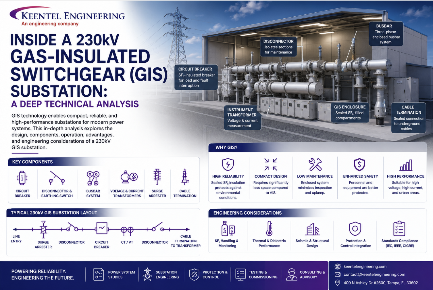
III. SUBSTATION LAYOUTS
A substation layout is the arrangement of various electrical equipment and components within a substation. The layout is designed to ensure safe and efficient operation of the substation and to meet the specific requirements of the electrical power system it serves.
Typically, a substation layout consists of the following components:
1. Power transformers – used to step up or step down the voltage of incoming electrical power.
2. Switchgear – used to control, protect, and isolate electrical equipment within the substation.
3. Busbars – conductors that transfer electrical power within the substation.
4. Circuit breakers – used to interrupt the flow of electrical current in case of a fault.
5. Protective relays – used to detect faults and trip the circuit breaker to isolate the faulted equipment.
6. Control panels – used to control and monitor the operation of the substation.
7. Instrument transformers – used to measure electrical quantities such as voltage, current, and power.
8. Lightning arresters – used to protect the substation equipment from lightning strikes.
9. Grounding system – used to ensure a safe path for electrical current in case of a fault.
The specific layout of a substation depends on the voltage levels, power capacity, and specific requirements of the electrical power system it serves. The layout must also comply with relevant electrical safety standards and regulations
IV. ACSR CONDUCTOR SIZING
ACSR (Aluminum Conductor Steel Reinforced) is a type of electrical conductor used in overhead transmission and distribution systems. It is a composite material consisting of an aluminum core surrounded by one or more steel wires. ACSR conductors are used in a variety of applications including substation power transmission and distribution.
The sizing of ACSR conductors in a substation is an important aspect of ensuring efficient and reliable power transmission. The size of the conductor determines its ability to carry electrical current without overheating and causing damage to the surrounding equipment. In this blog, we will explore the factors that need to be considered when selecting the appropriate size of ACSR conductor for a substation.
1. Load Requirements:
One of the primary considerations when selecting the size of ACSR conductor is the amount of electrical current that it will need to carry. The size of the conductor should be selected based on the load requirements of the substation, which will depend on the number of customers, the type of equipment being used, and other factors.
2. Voltage Level:
Another important factor to consider when sizing ACSR conductors is the voltage level of the substation. High voltage systems require larger conductors than low voltage systems, so it is important to take into account the voltage level when making a selection.
3. Distance of Transmission:
The distance of transmission is another important factor to consider when selecting the size of ACSR conductor. Conductors that are used over longer distances will require a larger cross-sectional area to reduce resistance and minimize energy loss.
4. Ambient Temperature:
The ambient temperature of the environment in which the ACSR conductor will be used is another important factor to consider. Conductors used in hot environments will require a larger cross-sectional area to prevent overheating and ensure efficient power transmission.
5. Safety Factors:
Finally, it is important to take into account safety factors when selecting the size of ACSR conductor. Conductors should be selected based on their ability to carry electrical current without overheating and causing damage to the surrounding equipment. This will depend on the specific requirements of the substation, and the safety factors should be determined by a licensed electrical engineer.
In conclusion, ACSR conductors play a critical role in ensuring efficient and reliable power transmission in substations. The size of the conductor should be selected based on the load requirements, voltage level, distance of transmission, ambient temperature, and safety factors. By considering these factors and working with a licensed electrical engineer, you can ensure that the ACSR conductor selected for your substation will meet your specific needs and provide reliable power transmission for years to come.
V. SHORT CIRCUIT CALCULATIONS DURING SUBSTATION DESIGN
Short circuit calculations are an important aspect of substation design, as they help to determine the maximum fault current that a substation can handle and ensure the safety of the equipment and personnel. Short circuit calculations are used to size the protective devices, such as circuit breakers and fuses, and to determine the necessary equipment ratings to ensure safe and reliable operation of the substation. Here are the steps involved in performing short circuit calculations during substation design:
1. Determine the system voltage:
The first step in performing short circuit calculations is to determine the system voltage. This will determine the maximum fault current that the system can handle and will be used in subsequent calculations.
2. Determine the short circuit current that is available:
The maximum fault is the available short circuit current that can flow in the system. This can be determined using the formula I = V / Z, where V is the system voltage and the system’s impedance is Z. The impedance of the system can be determined by analyzing the network and taking into account the resistance, inductance, and capacitance of the conductors and other components.
3. Determine the protective device ratings:
Once the available short circuit current has been determined, the protective device ratings can be calculated. The protective device rating is the maximum current that the device can handle without damaging itself or the equipment it is protecting. This will vary based on the substation’s unique needs, such as the size of the wires and the equipment in use.
4. Consider the time-current characteristics of the protective devices:
The time-current characteristics of the protective devices must also be taken into account when performing short circuit calculations. This refers to the time it takes for the protective device to operate and clear a fault, and is an important factor in ensuring the safety of the equipment and personnel.
5. Evaluate the equipment withstand capability:
Finally, it is important to evaluate the withstand capability of the equipment in the substation. This involves determining the maximum fault current that the equipment can handle without damage, and ensuring that the protective devices are rated accordingly.
In conclusion, short circuit calculations are a critical aspect of substation design, as they help to ensure the safety and reliability of the equipment and personnel. By performing accurate short circuit calculations, substation designers can determine the necessary equipment ratings and protective device ratings, and ensure that the substation is designed to meet the specific requirements of the application.
VI. CURRENT TRANSFORMER AND VOLTAGE
TRANSFORMER SIZING CALCULATIONS
When designing a substation, it is important to accurately size the current transformers (CTs) and voltage transformers (VTs) to ensure the proper operation of the protection and measurement equipment. Here are the general steps for sizing CTs and VTs:
A. Current Transformers:
- Determine the maximum current that will flow in the protected circuit. This is typically the highest short circuit current that can exist in the system.
- Select the CT rating that is appropriate for the maximum current. CTs are typically rated in terms of their secondary current, and the most common ratings are 5A or 1A.
- 3. Determine the accuracy class required for the CT. The accuracy class specifies the maximum error between the primary current and the secondary current. Common accuracy classes are 0.5, 0.2, and 0.1.
- Calculate the burden (load) on the CT secondary. The burden is the total impedance of the connected protection and measurement equipment.
- Check the CT’s knee point voltage to ensure it is suitable for the burden. The knee point voltage is the voltage that appears across the CT’s secondary winding when the primary current is equal to the CT’s rated primary current.
B. Voltage Transformers:
- Determine the voltage levels in the system, including the maximum and minimum operating voltages and the maximum transient overvoltages.
- Select the VT rating that is appropriate for the voltage levels. VTs are typically rated in terms of their secondary voltage, and the most common ratings are 110V or 120V.
- Determine the accuracy class required for the VT. The accuracy class specifies the maximum error between the primary voltage and the secondary voltage. Common accuracy classes are 0.5, 0.2, and 0.1.
- Calculate the burden (load) on the VT secondary. The burden is the total impedance of the connected protection and measurement equipment.
- Check the VT’s insulation level to ensure it is suitable for the voltage levels and burden.
- Note that these are general steps and the exact sizing calculations will depend on the specific system and equipment being used. It is always recommended to consult the manufacturer’s technical specifications and guidelines for the specific CTs and VTs being used.
VII. BUSBAR SIZING CALCULATIONS
Busbar sizing is an important aspect of substation design as it affects the electrical performance and stability of the system. The following are the general steps for busbar sizing calculations:
- Determine the maximum current that will flow through the busbar. This is typically the highest short-circuit current that can exist in the system.
- Choose the appropriate material for the busbar. Copper and aluminum are the most commonly used materials for busbars, but the choice will depend on factors such as cost, conductivity, and thermal conductivity.
- Determine the required cross-sectional area of the busbar based on the maximum current and the chosen material. The cross-sectional area determines the ampacity of the busbar, which is the maximum current it can carry without overheating.
- Consider the operating temperature and ambient temperature. The busbar must be able to operate within its temperature limits, and the ambient temperature must be taken into account when calculating the ampacity.
- Check the voltage drop across the busbar. The voltage drop should be within acceptable limits, typically 3% or less, to ensure proper operation of the equipment connected to the busbar.
6. Consider the busbar’s mechanical and thermal stability.
The busbar must be able to withstand the mechanical and thermal stresses caused by the current and temperature changes.
Note that these are general steps and the exact sizing calculations will depend on the specific system and equipment being used. It is always recommended to consult the manufacturer’s technical specifications and guidelines for the specific busbar material and installation requirements.
VIII. HT & LT CABLES AND CABLE TRAY SIZING CALCULATIONS AND VOLTAGE DROP CALCULATIONS
The sizing of high tension (HT) and low tension (LT) cables, as well as cable trays, is an important aspect of electrical design and engineering. The size of the cable and tray is determined by several factors, including the current carrying capacity, the voltage drop, and the temperature increase in the cable.
A cable’s current carrying capacity is the highest amount of current that it can safely carry without overheating. This capacity is determined by the conductor’s cross-sectional area, conductor material, and insulation type.
Voltage drop is the amount of voltage that is lost along the length of a cable as a result of resistance of the conductor. The drop in voltage is important because it affects the efficiency of the electrical system and can lead to problems such as equipment failure or reduced power output. The voltage drop is calculated using the formula:
Voltage drop = (2 * resistance * current) / 1000
where resistance is the resistance of the conductor in ohms per kilometer and current is the current flowing through the cable in amperes.
The temperature rise of a cable is the increase in temperature of the cable due to the flow of current. The temperature rise is important because it affects the durability and safety of the cable. The temperature rise is calculated using the formula:
Temperature rise = (current^2 * resistance) / (conductivity * cross-sectional area)
where conductivity is the conductivity of the conductor in Siemens per meter and cross-sectional area is the conductor’s cross-sectional area in square millimeters.
Cable tray sizing is determined by the total cross-sectional area of the cables that will be placed in the tray, as well as the type of cable tray being used (perforated, solid bottom, etc.). The cable tray must be large enough to accommodate the cables and allow for proper air circulation to dissipate heat.
In conclusion, the sizing of HT and LT cables and cable trays involves a consideration of several important factors, including current carrying capacity, voltage drop, and temperature rise. The calculations and considerations involved in sizing these components are crucial for ensuring the safe and efficient operation of an electrical system.
IX. CABLE TRAY LAYOUT
Cable tray layout in a substation is the arrangement of cable trays and their components, such as supports and conduit connections, that provide a means to support and protect electrical power cables within the substation. The layout is an important aspect of substation design as it affects the accessibility, maintenance, and safety of the electrical cables.
Here are some general guidelines for cable tray layout in a substation:
1. Cable tray routing:
Cable trays should be routed in a manner that minimizes the length of cable runs, reduces the number of bends, and provides easy access for maintenance and inspection.
2. Cable tray supports:
Cable trays should be supported at regular intervals to ensure stability and to prevent sagging. Supports should be designed to withstand the weight of the cables and any additional loads, such as wind or seismic forces.
3. Cable tray height:
Cable trays should be installed at a height that allows sufficient clearance for maintenance and inspection, while also reducing the risk of damage from equipment and vehicles.
4. Cable tray separation:
Cable trays should be separated from each other and from other equipment to prevent interference and to ensure adequate ventilation.
5. Conduit connections:
Cable trays should be connected to conduit systems to provide a transition from overhead to underground cable runs and to provide additional protection for the cables.
6. Cable tray material:
Cable trays should be made of a material that is durable, corrosion-resistant, and suitable for the operating environment of the substation.
7. Cable tray labeling:
Cable trays should be labeled to identify the type of cables they contain and their routing, which is important for maintenance and emergency response.
These guidelines are intended to provide a general overview of cable tray layout in substations. It is important to consult with electrical engineers and industry standards, such as the “National Electrical Code” (NEC) and the “International Electrotechnical Commission” (IEC), for more specific requirements and recommendations
X. BUSDUCT SIZING CALCULATIONS
Bus duct sizing calculations are an important aspect of substation design engineering, as it determines the capacity of the bus duct system to safely and efficiently transmit electrical power. The following steps can be followed to size a bus duct system:
1. Determine the load demand:
The first step is to determine the load demand, which is the total amount of electrical power that will be transmitted through the bus duct system.
2. Select the voltage level:
The next step is to select the voltage level for the bus duct system, which is usually either 11 kV or 33 kV.
3. Determine the short-circuit current:
The short-circuit current is a crucial factor in determining the size of bus ducts because it establishes the maximum current that may pass through the system in the event of a short circuit. The short-circuit current can be calculated using industry standard methods such as the symmetrical component method.
4. Select the conductor material:
The conductor material should have a high conductivity and high thermal capacity, with aluminum and copper being the most commonly used materials.
5. Determine the conductor size:
The conductor size is determined based on the load demand, voltage level, and short-circuit current, as well as the conductor material and the operating temperature of the bus duct system.
6. Select the bus duct configuration:
The bus duct configuration can be either single-phase or three phase, and can be either segregated or integral.
7. Determine the bus duct cross-sectional area:
The cross-sectional area of the bus duct is determined based on the conductor size, number of conductors, and the bus duct configuration.
8. Consider the bus duct insulation:
The bus duct insulation should be designed to withstand the electrical and thermal stresses of the bus duct system, and to provide adequate electrical insulation between the conductors.
9. Consider the bus duct cooling: The bus duct cooling system should be designed to prevent overheating of the conductors and the insulation, and to ensure safe and efficient operation of the bus duct system.
It’s important to follow industry standards and guidelines when performing bus duct sizing calculations, such as the IEEE Std 80-2013, to ensure safe and reliable operation of the bus duct system.
XI. LOAD CALCULATIONS
The breaker must have an operating mechanism that is reliable and capable of operating under the conditions of the electrical system.
In conclusion, the sizing of HV circuit breakers in substation design requires careful consideration of several technical and operational factors to guarantee the power system’s dependable and secure functioning.
1. Determine the type of load:
There are two types of loads in a substation – continuous and non continuous. Continuous loads are those that are always present, like lighting and air conditioning systems, while non-continuous loads are those that are not always present, like motors and transformers.
2. Determine the load density:
This is the amount of electrical power required per unit area. It is calculated by dividing the total power demand by the area of the substation.
3. Determine the load duration:
This is the amount of time that the load is present. It is important to consider the load duration as it affects the size of the equipment required to meet the load demand.
4. Determine the diversity factor of the load:
This is the ratio of a substation’s maximum demand to the aggregate of each load’s unique maximum needs. It takes into account the fact that not all loads will be present at the same time.
5. Calculate the load demand:
The load demand is calculated by multiplying the load density by the area of the substation and then by the diversity factor.
6. Select the equipment:
Based on the load demand calculation, the appropriate equipment such as transformers, switchgear, and circuit breakers can be selected to meet the electrical demand of the substation.
It is important to note that load calculations should be reviewed and updated regularly to ensure that the substation is equipped to handle changing electrical demands
XII. TRANSFORMER SELECTION AND SIZING
Transformer selection and sizing is a crucial step in the design of a substation. The right transformer size and type must be selected to meet the electrical requirements of the system and ensure safe, efficient, and reliable operation. The following are some of the key considerations in transformer selection and sizing:
1. Load requirements:
The transformer’s size must correspond to the system’s highest anticipated load demand. The load demand should be estimated based on the connected equipment and their power requirements.
2. Voltage levels:
The system’s voltage levels should be taken into account when selecting the transformer. Transformers are typically designed to change the voltage, either up or down in the system.
3. Efficiency:
The efficiency of the transformer should be considered when selecting and sizing the transformer. High-efficiency transformers can help reduce energy losses and lower operating costs.
4. Short-circuit capacity:
The transformer should be able to tolerate any potential short-circuit currents in the system. The short-circuit capacity of the transformer should be calculated based on the expected short-circuit currents in the system.
5. Environmental conditions:
The environmental conditions of the substation site should be taken into account when selecting the transformer. This includes temperature, humidity, altitude, and exposure to corrosive elements.
6. Safety considerations:
The safety of the transformer should be considered during the selection and sizing process. Transformers should meet relevant safety standards and certifications.
In summary, the selection and sizing of transformers in substation design is a complex process that requires careful consideration of various electrical, operational, and environmental factors. An experienced electrical engineer with knowledge of the specific requirements of the substation should be consulted to ensure the right transformer is selected and sized for the system.
XIII. DG SIZING
DG (Distributed Generation) Sizing for a Substation Design refers to the process of determining the size and capacity of a distributed generation system that needs to be installed in a substation to meet the energy needs of a specific location or distribution network.
The following are the key factors that need to be considered when sizing a DG system for a substation design:
1. Energy demand:
The first step is to determine the energy demand at the substation. This information can be obtained from energy consumption data for the area or by estimating the future energy demand based on growth projections.
2. Access to renewable energy sources:
The next step is to assess the availability of renewable energy sources such as solar, wind, or hydro power at the substation location.
3. System efficiency:
The efficiency of the DG system, including the conversion efficiency of the generators and the efficiency of the power electronics, must be taken into account when sizing the system.
4. Power quality requirements:
The power quality requirements, such as voltage and frequency stability, must be considered when sizing the DG system.
5. Grid connection requirements:
The requirements for connecting the DG system to the grid, including the voltage and frequency range, must be taken into account when sizing the system.
6. Cost considerations:
The cost of the DG system, including the initial investment and operating costs, must be considered when sizing the system.
Once all of these factors have been taken into account, the size and capacity of the DG system can be determined, and the substation design can be finalized. It is important to note that the DG sizing for a substation design is a complex process that requires a comprehensive understanding of the energy system, the available technology, and the economic and regulatory factors that impact the deployment of DG systems.
XIV. SINGLE LINE DIAGRAMS
A single line diagram (SLD) is a simplified representation of a substation, showing the main components and their connections. It is typically used during the design phase of a substation to provide a clear knowledge of the electrical equipment and their relationships.
The single line diagram will typically include the following components:
1. Power transformers:
These are utilized to increase or decrease the voltage of the incoming power.
2. Busbars:
The conductors that connect the transformers, generators, and other electrical equipment in the substation.
3. Circuit breakers:
Devices used to interrupt the flow of current in the event of an electrical fault.
4. Isolators:
Devices for isolating certain areas of the substation so they may be maintained or repaired. 5. Protective relays: Devices used to detect faults and trip the circuit breaker to isolate the faulted section. 6. Metering equipment: Devices used to measure the electrical parameters of the incoming and outgoing power.
7. Grounding system:
A network of conductors used to give fault current a low-impedance route to the earth. The single line diagram should also show the electrical connections between the components and the power flow direction. The diagram should be clear and easy to understand, with annotations and labels to explain the various components and their functions.
XV. LIGHTING CALCULATIONS
Lighting calculations are an important aspect of substation design as they ensure that the substation is well-lit, safe, and meets local regulations. The following steps are involved in lighting calculations during a substation design project:
1. Determine the lighting requirements:
This involves determining the light level (in lux or foot-candles) required for various areas within the substation such as the control room, switchyard, and other outdoor areas. The light-level requirements are usually specified in local regulations or industry standards.
2. Determine the light sources:
The next step is to determine the type of light sources to be used in the substation, such as LED lights, fluorescent lights, or high-intensity discharge (HID) lights. The choice of light source will depend on various factors such as cost, energy efficiency, and durability.
3. Calculate the number of light fixtures:
The number of light fixtures required for each area can be calculated using the formula: Number of fixtures = Total light output required / Light output per fixture
4. Determine the light distribution:
The light distribution pattern of the fixtures should be chosen to ensure uniform lighting and minimize shadows. This can be achieved by using fixtures with specific light distribution patterns or by using diffusers.
5. Perform a lighting simulation
A lighting simulation can be performed to verify that the proposed lighting design meets the required light levels. The simulation can also be used to identify any areas that may require additional lighting.
6. Review and revise the design:
The lighting design should be reviewed and revised as necessary to ensure that it meets the required light levels, is energy-efficient, and complies with local regulations.
In summary, lighting calculations during a substation design project involve determining the lighting requirements, selecting the light sources, calculating the number of light fixtures, determining the light distribution, performing a lighting simulation, and reviewing and revising the design as necessary.
XVI. LIGHTNING PROTECTIONS AND LAYOUTS
Lightning protection is an important aspect of substation design engineering as it helps to prevent damage to equipment and ensure the safety of personnel working in the substation. There are several methods for protecting a substation from lightning strikes, including the use of lightning rods, air terminals, down conductors, and earthing systems.
The layout of a substation is also important for lightning protection. The substation should be designed in such a way that there is a clear path for lightning to follow to the earth, minimizing the risk of damage to equipment and ensuring the safety of personnel. This can be achieved by ensuring that all tall structures, such as transmission towers and buildings, are equipped with air terminals, down conductors, and earthing systems. The earthing system should be designed to provide a low impedance path for lightning to follow to the earth, reducing the risk of damage to equipment and ensuring the safety of personnel.
It is also important to consider the layout of the substation with respect to surrounding structures and landscapes. For example, substations should be located away from large trees and other tall structures that could attract lightning strikes. Additionally, substations should be positioned on high ground to reduce the risk of flooding, which could compromise the effectiveness of the earthing system.
In conclusion, substation design engineers should give careful consideration to lightning protection and layout when designing a new substation. By implementing effective lightning protection measures and designing the substation layout in a way that minimizes the risk of damage to equipment and ensures the safety of personnel, engineers can help to ensure that the substation operates reliably and safely.
XVII. EARTHING CALCULATIONS AND LAYOUTS
Earthing is a critical aspect of substation design engineering as it ensures the safety of the equipment, personnel, and the public. The earthing system provides a low-resistance path to the ground for fault currents, which helps to limit the potential of electrical shock and equipment damage.
There are several steps involved in earthing calculations and layouts for a substation design:
1. Determining the earthing grid size:
The size of the earthing grid is dependent upon the fault current level and the type of soil at the substation site. To measure soil resistance, a soil resistivity test is conducted, which is then used to calculate the size of the earthing grid.
2. Earthing electrode selection:
The type of earthing electrode to be used in the substation depends on the soil resistivity and the fault current level. Common types of earthing electrodes include copper-bonded steel rods, ground plates, and earth mats.
3. Earthing grid layout:
The earthing grid layout is designed based on the earthing grid size and electrode selection. The earthing grid should be designed to provide a low-resistance path to ground and to ensure that the fault current is distributed evenly over the grid.
4. Earthing conductor sizing:
The size of the earthing conductor depends on the fault current level, the earthing electrode size, and the earthing grid layout. The earthing conductor should be sized to ensure that it can safely carry the fault current without overheating or melting.
5. Bonding and earthing connections:
All metallic parts of the substation equipment should be bonded together and connected to the earthing grid to ensure that they are at the same potential. This helps to prevent electrical shock and equipment damage.
6. Earthing resistance testing:
The earthing system should be tested after installation to ensure that it has a low resistance to ground. This can be done using a fall-of-potential test or a four-wire resistance test.
In conclusion, earthing calculations and layouts are crucial for the safe and reliable operation of a substation. Proper earthing design and installation are essential to guarantee the public’s, employees’, and equipment’s safety.
XVIII. POWER SYSTEM PROTECTION AND RELAY SETTINGS
Power system protection is a critical component of substation design and operation. It involves the use of relays, circuit breakers, and other protective devices to detect and isolate faults within the electrical power system. This helps to minimize damage and prevent widespread power outages. Relay settings are critical in determining the performance of protection systems. They control the operating characteristics of the relays and determine the conditions under which they will trip, or disconnect, the faulty section of the electrical system.
The following are some of the important aspects to consider when setting up the protection and control systems in a substation:
1. Zone of protection:
The zone of protection refers to the part of the electrical system that is monitored and protected by a particular relay. It is important to ensure that the relay settings are appropriate for the specific zone of protection in order to ensure that the relay operates as intended.
2. Time delay:
Time delay is the amount of time that a relay takes to trip after it has detected a fault. The time delay is important in order to allow the relay to differentiate between temporary and permanent faults.
3. Current settings:
The current setting of a relay determines the level of current that has to be met for the relay to trip. This setting should be appropriate for the type of fault that is expected to occur in the zone of protection.
4. Voltage settings:
The voltage setting of a relay determines the level of voltage that has to be met for the relay to trip. This setting should be appropriate for the type of fault that is expected to occur in the zone of protection.
5. Coordination:
Relays must be properly coordinated to ensure that they operate in the correct sequence during a fault. This helps to minimize the extent of the fault and prevent widespread power outages.
In conclusion, power system protection and relay settings contribute significantly to maintaining the safe and reliable functioning of substations. It is crucial to properly take into account the specific requirements of each substation and to set the protection and control systems accordingly.
XIX. LIGHTNING ARRESTER SIZING
A lightning arrester (LA) is an electrical safety device designed to protect electrical equipment, such as substations, from damage due to lightning strikes. Here is a general overview of the design of a lightning arrester in a substation:
6. Installation:
LAs are typically installed at the highest point of the substation, such as on the roof or on top of a tall structure. This allows them to be in close proximity to the lightning strikes and intercept them before they reach the electrical equipment.
7. Protection Zones:
A substation is divided into different protection zones, each of which requires a different level of protection from lightning. LAs are installed in each of these zones to provide an appropriate level of protection.
8. Surge Diverter:
The LA contains a surge diverter, which is a device that diverts the lightning current away from the electrical equipment. This is usually achieved through the use of a spark gap or a metal oxide varistor (MOV).
9. Grounding:
The LA is connected to a grounding system that creates a low-impedance conduit for lightning current to go through on its way to earth. This helps to reduce the voltage that the electrical equipment is exposed to during a lightning strike.
10. Monitoring and Testing
LAs should be regularly tested and monitored to ensure that they are functioning properly. This can be done through the use of surge generators, which simulate lightning strikes and test the performance of the LA.
In conclusion, the design of a lightning arrester in a substation involves the installation of the LA at the highest point, the division of the substation into different protection zones, the use of a surge diverter, the connection to a grounding system, and regular monitoring and testing.
XX. HV CIRCUIT BREAKERS SIZING
High voltage (HV) circuit breakers play a critical role in the protection and control of electrical power systems. The sizing of HV circuit breakers in substation design is an important aspect to guarantee the power system’s dependable and secure functioning. The following factors need to be considered when sizing HV circuit breakers:
1. Maximum continuous current:
This is the maximum current that the breaker is capable of carrying continuously without any damage to the breaker or the electrical system.
2. Maximum short-circuit current:
This is the greatest current that may pass through the breaker during a short-circuit event. The breaker must be able to interrupt the short-circuit current within a specified time.
3. Voltage level:
The breaker must be rated for the operating voltage of the electrical system.
4. System configuration:
The breaker must be selected based on the configuration of the electrical system, including the type of power transformers, generators, and other equipment connected to the breaker.
5. Short-circuit protection coordination:
The breaker must be selected to coordinate with other protective devices in the electrical system, such as fuses, reclosers, and protective relays, to ensure that the breaker operates within the specified time during a fault.
6. Breaking capacity:
The breaker must have sufficient breaking capacity to safely interrupt the maximum short-circuit current.
7. Operating mechanism:
XXI. BATTERY AND BATTERY CHARGER SIZING CALCULATIONS
In a substation design, the sizing of the battery and battery charger is an important aspect to consider ensuring proper operation of the backup power system. The following are the steps involved in calculating the size of the battery and battery charger:
1. Determine the load requirements:
The first step is to determine the load requirements, which includes the total power requirement of the equipment in the substation that needs to be powered by the backup system in the event of a power failure.
2. Calculate the battery capacity:
The next step is to calculate the battery capacity, which is the amount of energy stored in the battery. This is calculated based on the load requirements, the discharge time required, and the discharge rate of the battery.
3. Determine the battery voltage:
The voltage of the battery is measured depending on the voltage needs of the equipment in the substation.
4. Calculate the battery current:
The battery current is calculated by dividing the battery capacity by the battery voltage.
5. Determine the battery charger size:
The size of the battery charger is determined based on the battery current and the charging time required to fully charge the battery.
6. Calculate the battery charger voltage:
The voltage of the battery charger is measured depending on the voltage demand of the battery.
7. Calculate the battery charger current:
The battery charger current is calculated by dividing the battery capacity by the charging time required and the battery charger voltage.
8. Select the battery and battery charger:
Based on the calculations, a suitable battery and battery charger are selected from the available options in the market.
It is important to note that the calculations need to be done carefully to ensure that the battery and battery charger are appropriately sized for the substation requirements. A battery and battery charger that is undersized may not provide sufficient backup power during an outage, while an oversized battery and battery charger may result in unnecessary costs
XXII. UPS SIZING CALCULATIONS
UPS (Uninterruptible Power Supply) sizing during substation design engineering involves determining the amount of power required to keep the substation’s critical loads running in the event of a power outage. The calculation involves several factors, including:
1. Load Capacity:
The first step is to determine the total load capacity of all the critical loads that the UPS
needs to support. This includes all electrical equipment such as transformers, switchgear, and control systems.
2. Power Consumption:
The next step is to determine the power consumption of each critical load. This includes both the active power (measured in kilowatts) and the reactive power (measured in kilovars).
3. Operating Time:
The next step is to determine the operating time of the UPS. This is the time required to keep the critical loads running in the event of a power outage. A typical operating time is between 10 minutes and 4 hours.
4. Battery Capacity:
The next step is to determine the battery capacity required to support the critical loads during the operating time. This is calculated based on the total load capacity and the operating time.
5. Inverter Capacity:
The final step is to determine the inverter capacity needed for converting DC power to AC power from the battery to supply the critical loads. This is calculated based on the total load capacity and the operating time.
It’s important to note that UPS sizing calculations should be done by a qualified electrical engineer with experience in power system design. The calculations should take into account the specific requirements of the substation, including the location, environment, and local electrical codes and standards.
REFERENCES
[1] M. Kezunovic, Y. Guan, C. Guo, and M. Ghavami, “The 21st century substation design: Vision of the future,” in 2010 IREP Symposium Bulk Power System Dynamics and Control – VIII (IREP), Aug. 2010, pp. 1–8. doi: 10.1109/IREP.2010.5563267.
[2] J. D. McDonald, Ed., Electric Power Substations Engineering, 1st ed. CRC Press, 2003. doi: 10.1201/9780203486498.
[3] D. Atanackovic, D. T. McGillis, and F. D. Galiana, “The application of multi-criteria analysis to substation design,” IEEE Transactions on Power Systems, vol. 13, no. 3, pp. 1172–1178, Aug. 1998, doi: 10.1109/59.709116.
[4] L. Zhao, I. Brandao Machado Matsuo, Y. Zhou, and W.-J. Lee, “Design of an Industrial IoT-Based Monitoring System for Power Substations,” IEEE Transactions on Industry Applications, vol. 55, no. 6, pp. 5666–5674, Nov. 2019, doi: 10.1109/TIA.2019.2940668.
[5] M. Kezunovic and G. Latisko, “Automated monitoring functions for improved power system operation and control,” in IEEE Power Engineering Society General Meeting, 2005, Jun. 2005, pp. 2708-2711 Vol. 3. doi: 10.1109/PES.2005.1489699.
[6] Q. B. Dam, A. P. S. Meliopoulos, G. T. Heydt, and A. Bose, “A Breaker-Oriented, Three-Phase IEEE 24-Substation Test System,” IEEE Transactions on Power Systems, vol. 25,
At Keentel Engineering, our substation design expertise spans the full engineering lifecycle—from early-stage feasibility studies and electrical system layouts to advanced protection and grounding strategies. Whether you’re planning a utility substation, distribution substation, or upgrading an existing facility, we ensure every design meets global standards (IEEE, IEC, IS) for performance, safety, and compliance. Our solutions incorporate substation lighting design, busbar and cable sizing, relay coordination, and short-circuit analysis—delivered with precision and backed by decades of hands-on field experience. If you’re seeking reliable electrical substation design services that support future-ready infrastructure, Keentel is your trusted engineering partner.
For more about our Power System Studies or Utility-Scale Battery Storage Engineering, explore our full engineering services.
Reach out at www.keentelengineering.com
Email: contact@keentelengineering.com | Call: 813-389-7871

About the Author:
Sonny Patel P.E. EC
IEEE Senior Member
In 1995, Sandip (Sonny) R. Patel earned his Electrical Engineering degree from the University of Illinois, specializing in Electrical Engineering . But degrees don’t build legacies—action does. For three decades, he’s been shaping the future of engineering, not just as a licensed Professional Engineer across multiple states (Florida, California, New York, West Virginia, and Minnesota), but as a doer. A builder. A leader. Not just an engineer. A Licensed Electrical Contractor in Florida with an Unlimited EC license. Not just an executive. The founder and CEO of KEENTEL LLC—where expertise meets execution. Three decades. Multiple states. Endless impact.
Services

Let's Discuss Your Project
Let's book a call to discuss your electrical engineering project that we can help you with.
About the Author:
Sonny Patel P.E. EC
IEEE Senior Member
In 1995, Sandip (Sonny) R. Patel earned his Electrical Engineering degree from the University of Illinois, specializing in Electrical Engineering . But degrees don’t build legacies—action does. For three decades, he’s been shaping the future of engineering, not just as a licensed Professional Engineer across multiple states (Florida, California, New York, West Virginia, and Minnesota), but as a doer. A builder. A leader. Not just an engineer. A Licensed Electrical Contractor in Florida with an Unlimited EC license. Not just an executive. The founder and CEO of KEENTEL LLC—where expertise meets execution. Three decades. Multiple states. Endless impact.
Leave a Comment
We will get back to you as soon as possible.
Please try again later.
Related Posts