
Executive Summary
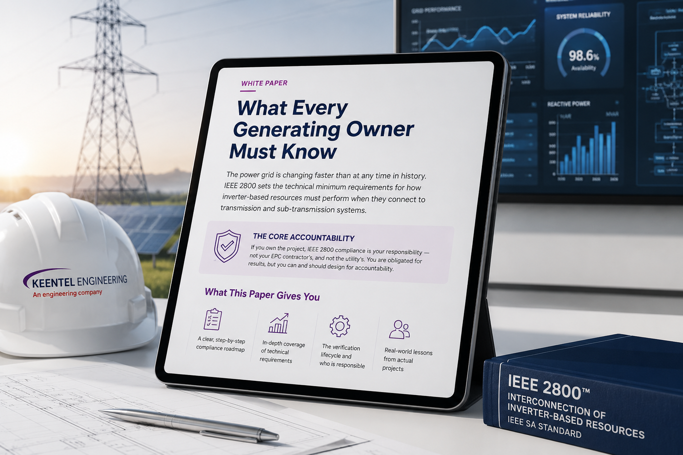
What Every Generating Owner Must Know
The power grid is changing faster than at any time in its history. Solar farms, wind plants, and battery energy storage — collectively called inverter-based resources, or IBRs — now make up a large and growing share of the generation connecting to the bulk power system. These resources behave very differently from the large spinning machines that built the grid. They have almost no physical inertia, their output is governed by software and power electronics rather than the laws of rotating mass, and when they are disturbed they can all react in the same way at the same instant.
That difference is not theoretical. Over the past decade, grid operators documented several large disturbances in which thousands of megawatts of solar generation tripped off-line almost simultaneously in response to a single, ordinary fault on the transmission system — a fault the grid should have shrugged off. Investigations traced these events to inverter settings and control behaviors that were never coordinated with the needs of the grid. IEEE 2800™-2022 is the industry's answer.
IEEE 2800 establishes uniform, technical minimum requirements for how IBRs must perform when they connect to transmission and sub-transmission systems. It covers how a plant supports voltage, how it responds to changes in frequency, how it must ride through disturbances instead of tripping, the quality of power it injects, how it coordinates protection, the models it must hand over, and — critically — how all of this must be tested, evaluated, and proven across the entire life of the plant.
The Core Accountability
If you own the project, IEEE 2800 compliance is your responsibility — not your inverter vendor's, not your EPC contractor's, and not the utility's. You can delegate the work, but you cannot delegate the accountability.
What this paper gives you
- A clear map of the players — who the Generating Owner is and how that role sits among the utility, the operator, and the regulator.
- A step-by-step compliance journey — the eight phases every GO must work through, from first study to lifetime operation.
- Plain-language deep dives — reactive power, frequency response, ride-through, power quality, protection, modeling, and monitoring, explained without losing the engineering.
- The verification lifecycle — type tests, design evaluation, commissioning, and ongoing validation, and who is on the hook for each.
- Twenty detailed FAQs and three anonymized case studies drawn from real-world interconnection challenges.
The recurring theme is simple: IEEE 2800 is a performance standard, not a checklist. It does not tell you which equipment to buy or how to wire it. It tells you how the finished plant must behave at a specific point on the grid — and then requires you to prove it, on paper and in the field. Meeting it demands the kind of cross-disciplinary judgment that only comes from deep, hands-on transmission and distribution experience.
Background
Why IEEE 2800 Exists
The grid was built for spinning machines
For a century, electricity came from large synchronous generators — massive rotating machines in coal, gas, nuclear, and hydro plants. These machines store energy physically in their spinning mass. When something goes wrong on the grid, that stored inertia buys the system precious seconds, and the machines' natural physics push back against voltage and frequency swings without anyone telling them to. The grid's protection schemes, planning studies, and operating habits were all built around this behavior.
Inverter-based resources are fundamentally different
An inverter-based resource — a solar PV plant, a modern wind farm, or a battery storage system — connects to the grid through power-electronic inverters. There is no large spinning mass directly tied to grid frequency. Everything the resource does in response to a disturbance is a decision made by control software in milliseconds. This brings real advantages (speed, precision, flexibility) but also real risks:
- Correlated behavior: thousands of inverters running similar firmware can all react identically to the same event, turning a local problem into a system-wide loss of generation.
- Hidden trip settings: default factory protection settings, if left uncoordinated, can cause a plant to disconnect during a disturbance it was perfectly capable of withstanding.
- Low inertia: as inverter-based generation displaces spinning machines, the grid has less natural cushioning, so the way IBRs respond to frequency events matters more than ever.
- Weak-grid interactions: in remote areas with a low short-circuit ratio, inverter controls can interact with the network and with each other in unstable ways that simple models never reveal.
Real disturbances drove the standard
Following several widely studied disturbances in which large blocks of solar generation unexpectedly reduced or tripped after routine transmission faults, the North American Electric Reliability Corporation (NERC) published reliability guidelines recommending firm, uniform interconnection requirements for IBRs. IEEE 2800 grew directly out of that work, developed by a broad working group of utilities, manufacturers, consultants, researchers, and regulators, and approved in 2022. It converts hard-won lessons into enforceable, measurable performance requirements.
The Core Idea in One Sentence
IEEE 2800 makes sure that when the grid has a bad day, inverter-based resources help hold it together instead of making the problem worse.
▶ Video — Understanding IEEE 2800 Requirements
Roles & Responsibilities
Who's Who: The Generating Owner and Everyone Else
IEEE 2800 carefully separates the different roles in an interconnection so that each requirement lands on the right party. The standard uses the term IBR owner; in the North American reliability framework this maps to the registered Generator Owner (GO), which throughout this paper we call the Generating Owner.
Generating Owner (GO) / IBR owner
Owns the resource and is responsible for its design conformance and maintenance. In IEEE 2800, this is the entity that requests the interconnection. The standard does not separate the owner from the developer.
You. You own the asset, you request to connect, and the buck stops with you for proving the plant meets the standard.
Generating Operator (GOP) / IBR operator
Monitors and operates the resource through its local control interface; implements setting and mode changes.
The team — sometimes the same company, sometimes a third party — that runs the plant day to day.
Transmission System (TS) Owner
Designs, builds, and owns the transmission facilities the plant connects to; specifies many local requirements.
The wires company that owns the grid you plug into.
TS Operator
Operates the transmission system in real time; directs the plant, approves test procedures, and sets many default values.
The control room that tells the grid (and you) what to do moment to moment.
AGIR
Authority Governing Interconnection Requirements — the body that decides whether and how IEEE 2800 applies in a given region.
The rule-maker that adopts the standard and decides which voltages and projects it covers.
Verification Entity
Performs or witnesses type tests, evaluations, and commissioning tests.
The independent expert that signs off that the proof is real.
The Single Most Important Takeaway
IEEE 2800 explicitly makes the IBR owner — the Generating Owner — the entity that requests interconnection and carries responsibility for conformance. Inverter manufacturers supply capable equipment and type-test data. EPC contractors build to a design. But it is the GO who must pull every piece together and demonstrate, at the agreed point on the grid, that the whole plant performs. Expertise on your side of the table is not optional.
Core Concepts
The Big Picture: Three Ideas That Unlock the Whole Standard
Before the step-by-step requirements make sense, three concepts have to be clear. Get these, and the rest of IEEE 2800 falls into place.
1. It is a performance standard, not a design standard
IEEE 2800 almost never says "install this device" or "use that setting." Instead it says "the plant shall behave this way at this point on the grid." How you achieve that behavior — which inverters, which plant controller, whether you add a STATCOM or capacitor banks or rely on the inverters alone — is left to you. This freedom is powerful, but it shifts the burden of proof squarely onto the Generating Owner.
2. Everything is measured at the Reference Point of Applicability (RPA)
Requirements do not apply "at the inverter" or "somewhere in the plant." They apply at a defined electrical location called the Reference Point of Applicability (RPA). By default this is the Point of Measurement (POM), often at or near the Point of Interconnection (POI). Compliance is judged on the aggregate plant at the RPA — not on any single piece of equipment.
3. The obligation lasts the entire life of the plant
IEEE 2800 is not a one-time gate you clear at energization. Its requirements are intended to apply over the lifetime of the plant. If you change firmware, swap hardware, or adjust protection settings, you may re-trigger verification. Compliance is a program you run for decades, not a certificate you frame on the wall.
Compliance Journey
Speak to an Engineer →
Step by Step: What the Generating Owner Must Do
Here is the whole journey, organized into eight phases. Each phase lists the GO's obligations in plain terms and flags where deep engineering judgment makes or breaks the outcome.
1
Understand the Rules That Actually Apply to You
▾
IEEE 2800 is adopted and tailored by your regional authority (the AGIR) and refined by the TS owner and TS operator. Many values in the standard are defaults the utility can tighten. Your first job is to assemble the real, project-specific rulebook.
- Confirm with the AGIR / utility that IEEE 2800 applies to your project and at what voltage.
- Obtain the TS owner/operator's specific settings, default values, and any stricter local requirements.
- Identify the agreed RPA (usually the POM) for each requirement family.
- Map IEEE 2800 obligations against any overlapping NERC standards (e.g., the MOD, PRC, and VAR families).
Why expertise matters:
Getting the wrong rulebook means designing to the wrong target. The defaults in the standard are starting points; the binding numbers come from your interconnection agreement and the utility's specifications.
2
Register the Plant and Its Ratings
▾
During the interconnection process the GO registers the plant's key ratings with the TS operator or AGIR so the utility can study the grid impact.
- Register the IBR Continuous Rating (ICR), and the short-term rating (ISR) if applicable.
- For storage, also register the IBR Continuous Absorption Rating (ICAR) — how much the plant can charge.
- Provide any additional registration data the TS operator requests.
Why expertise matters:
These ratings anchor nearly every capability requirement in the standard. Register them carelessly and every downstream study — and your obligations — are built on sand.
3
Design the Plant to Deliver the Required Capabilities
▾
This is where the standard's performance requirements become engineering decisions. The plant must be designed — inverters, plant controller, transformers, and any supplemental devices — so that the aggregate behavior at the RPA meets every applicable requirement.
- Reactive power & voltage control: size the plant to inject and absorb reactive power across the voltage band, and implement voltage-control, power-factor, and reactive-power modes.
- Frequency response: implement primary frequency response (adjustable droop and deadbands) and, where required, fast frequency response.
- Ride-through: configure inverter and plant protection so the plant stays connected through voltage and frequency disturbances inside the defined envelopes.
- Dynamic support: ensure the plant injects reactive (and negative-sequence) current during faults to support voltage.
- Power quality: design so flicker and harmonic emissions stay within limits at the RPA.
- Protection coordination: ensure every protective function is coordinated with the grid and never defeats ride-through.
Why expertise matters:
A pile of individually capable inverters does not guarantee a compliant plant. Capability has to be engineered, aggregated, and tuned to land correctly at the RPA — the central challenge of IEEE 2800 design.
4
Prove It on Paper — The Design Evaluation
▾
Before anything is built, the GO must demonstrate through engineering study (a "desk study") that the design will meet the requirements. This is modeling and simulation — no field testing yet — and it is the linchpin of the whole verification framework.
- Develop and validate plant-level models: power-flow, positive-sequence dynamic (stability), electromagnetic transient (EMT), short-circuit, and harmonic models.
- Run the studies that show ride-through, reactive capability, frequency response, and power quality are met at the RPA.
- Determine which requirements need commissioning tests or extra monitoring based on the study results.
- Document every model, assumption, and result for the utility's interconnection review.
Why expertise matters:
Many plant-level requirements simply cannot be proven by testing a single inverter — they only emerge in simulation of the whole plant against the grid. EMT studies for weak grids in particular separate projects that energize smoothly from those that stall in re-studies for months.
5
Build It to Match the Design
▾
The plant as constructed must match the plant as evaluated. An as-built installation evaluation confirms that the inverters, collector system, supplemental devices, and protective functions delivered to site meet or exceed the evaluated design.
- Verify installed equipment, firmware versions, and settings against the design basis.
- Capture and reconcile any field changes back into the models and documentation.
Why expertise matters:
A last-minute inverter substitution or a firmware update on the loading dock can silently break compliance. Disciplined configuration control is an engineering function, not a paperwork formality.
6
Demonstrate It in the Field — Commissioning Tests
▾
With the plant built, field tests on units and/or the whole plant verify that it performs as designed and installed. All tests follow written procedures, approved by the TS operator as required.
- Prepare written commissioning test procedures and obtain utility approval.
- Execute operability and functional performance tests (e.g., reactive capability, control modes, enter-service behavior).
- Document results formally and resolve any deviations.
Why expertise matters:
Commissioning is where design assumptions meet reality. Tests must be designed to actually exercise the requirement at the RPA — a poorly scoped test plan passes a non-compliant plant or fails a compliant one.
7
Validate the Models Against Reality
▾
After commissioning, the GO must validate that the models handed to the utility actually predict how the real plant behaves — the post-commissioning model validation step.
- Compare model predictions against commissioning and early-operation measurements.
- Refine and re-submit verified "as-built" models and documentation.
Why expertise matters:
Utilities plan the grid using your models. A model that does not match the plant is a liability for the whole system — and a frequent source of post-energization disputes.
8
Operate, Monitor, and Maintain Compliance for Life
▾
Compliance continues for the operating life of the plant. The GO/GOP must monitor performance, record disturbances, support event analysis, and re-verify after material changes.
- Maintain measurement and recording capability for performance monitoring, event analysis, and disturbance-based model validation.
- Re-trigger verification after firmware changes, hardware swaps, or protection-setting changes.
- Coordinate remedial measures with the utility if grid conditions change materially.
- Keep formal documentation current and audit-ready.
Why expertise matters:
Most compliance failures are discovered years after energization — in an event report — when it is most expensive to fix. A lifetime monitoring and configuration-control program is the only real protection.
Need Help With Your Design Evaluation?
Keentel's engineers have cleared design evaluations for solar, wind, and storage projects across weak and strong grid interconnections.
Technical Requirements
The Technical Requirements, Explained Simply
This section unpacks each major requirement family. The goal is to make the engineering understandable without watering it down. Values shown are the standard's defaults or ranges; your utility may specify stricter numbers.
6.1 — Reactive Power and Voltage Control
Reactive power is the part of electricity that does not do useful work but is essential for holding voltage steady. Too little and voltage sags; too much and it climbs. IEEE 2800 requires every plant to be a good voltage citizen at the RPA.
- Capability: the plant must inject and absorb reactive power equal to at least about 33% of its rating (roughly a 0.95 power factor) while delivering full active power, across the normal voltage band.
- Control modes: voltage-regulation mode (droop up to 0.3 p.u.), power-factor mode, and reactive-power mode — switchable on the utility's instruction.
- Dynamic response: start responding within 200 ms of a voltage step; settle with a damping ratio of at least 0.3. Stability wins over raw speed.
- Storage: batteries must provide reactive support whether charging or discharging, including through the transition.
Why It's Hard
Reactive capability measured at the inverter is eaten away by transformers and collector cables before it reaches the RPA. Delivering the required reactive range at the POM — economically — often calls for careful trade-offs between oversizing inverters, plant-controller tuning, and adding supplemental devices.
6.2 — Frequency Response
Grid frequency (60 Hz in North America) reflects the instant-by-instant balance between generation and load. When frequency drifts, resources are expected to push it back.
- Primary Frequency Response (PFR): automatic droop-based active-power adjustment (commonly ~5% droop) with adjustable deadbands for under- and over-frequency.
- Fast Frequency Response (FFR): where required, an even faster response that exploits inverter speed — something traditional machines cannot easily provide.
- Storage advantage: batteries can respond in both directions (charge or discharge), making them especially valuable for frequency support.
6.3 — Ride-Through: The Heart of the Standard
Ride-through means staying connected and supporting the grid through a disturbance instead of tripping off. The standard is blunt: if a plant trips because of its own protection while inside a defined ride-through envelope, that is non-compliance — full stop.
| Voltage at RPA | Required Behavior | Min. Time (with aux. limits) | Min. Time (without) |
|---|---|---|---|
| Above 1.20 p.u. | May ride through or may trip | — | — |
| 1.10 – 1.20 p.u. | Mandatory operation | 1.0 s | 1.0 s |
| 0.90 – 1.05 p.u. | Continuous operation | Continuous | Continuous |
| Below 0.90 p.u. | Mandatory operation | 3.0 s | 6.0 s |
Dynamic voltage support during faults: during a voltage dip the plant must actively inject reactive current to prop up voltage, and during a swell it must absorb. For unbalanced faults, inverters must also inject negative-sequence current to help the grid's protection detect and clear the fault.
Why Ride-Through Is Hard
Ride-through is governed by the interaction of inverter firmware, plant-controller logic, and dozens of protection settings across the plant. A single mis-set relay or aggressive self-protection threshold can trip a plant that was fully capable of riding through. Proving ride-through at the RPA requires EMT-level study and meticulous protection coordination.
▶ Video — PSCAD Modeling Explained: EMT Simulations for Modern Power Systems
6.4 — Power Quality
Inverters switch at high speed and can inject distortion. IEEE 2800 caps what the plant may emit at the RPA:
- Flicker: short-term (Pst) limited to 0.35; long-term (Plt) to 0.25.
- Harmonics: current-distortion limits per the IEEE 519 framework.
- Overvoltage: limits on the temporary overvoltage the plant may contribute.
Verification
How Compliance Is Proven: The Verification Lifecycle
IEEE 2800 does not take your word for it. It defines a sequence of verification methods, and a matrix specifying which methods apply to which requirement.
Notice Where the Weight Falls
Manufacturers own the type tests, but the design evaluation, as-built check, commissioning, model validation, and lifetime monitoring all sit with the Generating Owner and its operator. That is the majority of the work, and the part that demands the deepest engineering. Good engineering early reduces your obligations later.
▶ Video — Grid Reliability in the 2030s: Resource Adequacy in Decarbonizing Power Systems
Engineering Expertise
Why a Generating Owner Needs Deep Engineering Expertise
IEEE 2800 hands the Generating Owner a performance target, freedom in how to hit it, and full accountability for proving it — across modeling, controls, protection, power systems, and testing, over the entire life of the plant.
Where Projects Go Wrong
- Assuming certified inverters equal a compliant plant. Equipment certification is a building block, not a finished building.
- Treating the design evaluation as a formality. Weak-grid and ride-through problems surface in EMT study — and if you find them late, you re-study, re-design, and miss your energization date.
- Under-scoping models. Models that do not match the plant trigger utility rejections.
- Poor protection coordination. The leading cause of the very disturbances IEEE 2800 was written to prevent.
- No configuration control. A firmware update or setting change quietly breaks compliance.
How Keentel Engineering Helps
Keentel Engineering was built to carry exactly these obligations alongside the Generating Owner — from the first feasibility study to lifetime compliance support. We combine utility-side, developer-side, manufacturer-side, and regulator-side experience.
Know the Real Rulebook
Requirement mapping across IEEE 2800, the interconnection agreement, and overlapping NERC standards.
Compliant, Cost-Effective Design
Reactive-capability, control-mode, and protection design optimized to land at the RPA.
Pass the Design Evaluation
Power-flow, dynamic, EMT, short-circuit, and harmonic studies — including weak-grid analysis.
Build and Commission Cleanly
As-built evaluation, written commissioning procedures, test witnessing, and deviation resolution.
Models the Utility Will Accept
Verified, validated model packages with full documentation.
Stay Compliant for Decades
Monitoring strategy, event analysis, configuration control, and re-verification after changes.
The Keentel Difference
We have sat on every side of the interconnection table — at a major utility and generation owner, at developers, and at a regional reliability entity. That breadth means we anticipate the utility's questions before they are asked, design to pass the first time, and keep your asset compliant for its full life.
▶ Video — Inverter-Based Resources Modeling: DER Grid Studies, T&D Co-Simulation & EMT Explained
Real-World Experience
Three Anonymized Case Studies
The following engagements are anonymized and are representative of the interconnection challenges Generating Owners routinely face under IEEE 2800-style requirements.
Case Study 1 · Solar PV · Weak Grid
The Weak-Grid Solar Plant That Failed Ride-Through on Paper
The Challenge
A several-hundred-megawatt solar project was interconnecting at a remote point with a very low short-circuit ratio. When the utility required an EMT-based design evaluation, the plant model showed sustained oscillations during recovery from faults.
Keentel's Approach
Built a validated EMT model from actual inverter control data. Reproduced the oscillatory behavior, isolated it to plant-controller interactions. Re-tuned control parameters and defined a supplemental reactive device.
The Outcome
The re-engineered design rode through the full fault set with well-damped recovery. The project cleared the utility's design evaluation without entering the re-study queue.
Lesson:
On weak grids, EMT study quality is the project. Generic models cannot reveal these interactions.
Case Study 2 · Battery Storage · Reactive Shortfall
The Battery Plant That Could Not Deliver Reactive Power Where It Counted
The Challenge
A battery storage plant's design fell short of the required reactive injection and absorption range at the Point of Measurement after losses were accounted for.
Keentel's Approach
Quantified the reactive shrinkage from inverter terminals to the RPA. Evaluated options and implemented a coordinated plant-controller and tap solution.
The Outcome
The plant met its reactive-power obligations with a solution cheaper than inverter oversizing, and passed commissioning tests without rework.
Lesson:
Reactive capability is a plant-level property. Designing to inverter nameplate alone is one of the most costly mistakes — entirely avoidable with early analysis.
Case Study 3 · Operating Plant · Protection Failure
The Post-Energization Trip That Should Never Have Happened
The Challenge
An already-operating plant tripped off-line during a routine, distant transmission fault — a ride-through event. The utility flagged the trip as a potential compliance failure.
Keentel's Approach
Pulled high-resolution disturbance recordings. Traced the trip to an aggressive inverter-level self-protection threshold never coordinated with plant protection. Re-coordinated settings across units and plant.
The Outcome
The corrected settings demonstrated ride-through capability. The event analysis satisfied the utility and a configuration-control process was put in place to prevent recurrence.
Lesson:
Most compliance failures are discovered in the field, at the worst possible time. Disciplined protection coordination up front is the cheapest insurance.
Frequently Asked Questions
Get a Free Assessment →
Twenty Frequently Asked Questions
Detailed answers, written in plain language. Where the standard gives default values, your utility may set stricter ones.
1. What exactly is IEEE 2800, and is it mandatory?
IEEE 2800-2022 is the industry standard defining the technical minimum performance requirements for inverter-based resources. By itself, an IEEE standard is voluntary. It becomes mandatory when a regulator adopts it or a utility writes it into interconnection requirements. In practice, across North America it is rapidly becoming the de facto requirement for new transmission-connected IBRs.
2. How do I know if it applies to my project?
Applicability is set by your regional authority and utility. Confirm in writing with your interconnecting utility early, because the answer drives your entire design basis.
3. Who is actually responsible for compliance — me, my inverter vendor, or my EPC?
You, the Generating Owner. IEEE 2800 names the IBR owner as responsible for conformance. Vendors provide capable equipment; your EPC builds to a design. But assembling the proof that the whole plant performs — and maintaining it for life — is your responsibility.
4. My inverters are UL 1741-certified. Doesn't that make my plant compliant?
No. Equipment certification is explicitly outside the scope of IEEE 2800 compliance. Certification tells you an inverter behaves a certain way at its terminals. IEEE 2800 is judged on the aggregate plant at the reference point — after transformers, cables, losses, and the plant controller have all had their effect. Certified equipment is necessary, not sufficient.
5. What is the "RPA" and why does it keep coming up?
The Reference Point of Applicability is the specific electrical location where a requirement is measured — by default the Point of Measurement, usually near the Point of Interconnection. It matters because performance at an inverter's terminals is very different from performance at the plant boundary.
6. What does "ride-through" actually require my plant to do?
It requires the plant to stay connected and keep supporting the grid through voltage and frequency disturbances that fall inside defined envelopes. During faults it must inject reactive current to support voltage. If it trips inside these envelopes, that is non-compliance.
7. What is reactive power capability, and how much do I need?
Reactive power holds voltage steady. IEEE 2800 requires your plant to supply and absorb reactive power equal to at least about a third of its rating while producing full active power — all measured at the RPA. Reactive capability erodes between inverters and the RPA, so the plant must be engineered to deliver it where it is measured.
8. Do I really need an EMT model? They are expensive.
Often, yes — especially for weak-grid interconnections and for verifying ride-through. EMT models capture fast, detailed interactions that simpler models miss entirely. The expense of a good EMT model is small next to the cost of a failed design evaluation or a re-study delay.
9. What is a "weak grid" and why does it complicate everything?
A weak grid is one with a low short-circuit ratio — common at remote, high-renewable locations. On weak grids, inverter controls can interact with the network in unstable ways. These plants demand the most careful EMT modeling, control tuning, and sometimes supplemental equipment.
10. How early should I bring in an engineering firm?
As early as feasibility and interconnection-application stage — before the design is locked. The cost of expertise early is small next to the cost of waiting: failed design evaluations, re-study delays, missed energization dates, financing delays, and expensive redesigns.
Ready to Start Your IEEE 2800 Compliance Journey?
From feasibility through lifetime compliance — Keentel carries the technical weight alongside you.
About the Author
Sonny Patel, PE
Sonny Patel, PE is the Chief Executive Officer of Keentel Engineering and a licensed Professional Engineer in multiple states. He brings more than three decades of transmission and distribution engineering experience and was a contributing member of the IEEE 2800 working group.
His career spans every vantage point of the interconnection process: 17 years with Exelon; approximately 4 years supporting Alco hydropower; approximately 3.5 years with EDF Power Solutions; about 1.5 years with SERC Reliability Corporation — a NERC Regional Entity — giving him a regulator's perspective; and about 3 years in the mining sector on heavy industrial power systems.
This combination — utility, generation owner, renewable developer, and regional reliability entity — is rare, and it is precisely the breadth IEEE 2800 compliance demands.
Disclaimer.
This white paper is an educational summary prepared for general information. It paraphrases and interprets concepts from IEEE Std 2800™-2022 in plain language and is not a substitute for the standard itself, for your interconnection agreement, or for the requirements of your authority governing interconnection requirements. Specific values cited are the standard's defaults or ranges and may be superseded by stricter utility or regulatory requirements. The case studies are anonymized and representative. For project-specific advice, consult qualified engineers. IEEE and IEEE 2800 are trademarks of The Institute of Electrical and Electronics Engineers, Inc.
© 2026 Keentel Engineering. Authored by Sonny Patel, PE. All rights reserved.
© 2026 Keentel Engineering. Authored by Sonny Patel, PE. All rights reserved.


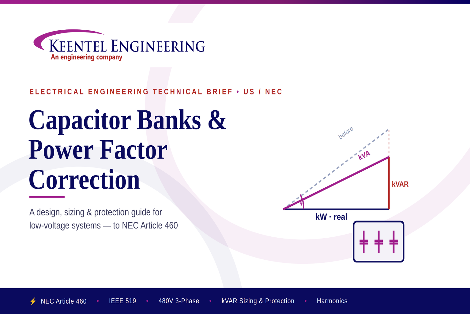
Learn capacitor bank sizing, power factor correction, NEC Article 460 requirements, harmonic mitigation, protection, and installation for industrial power systems.
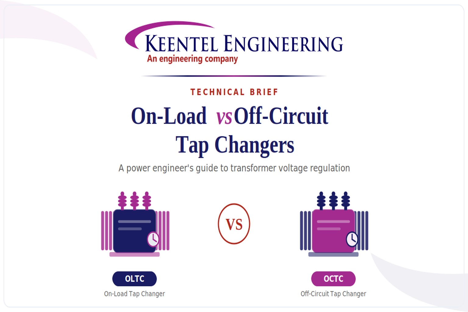
Learn the differences between On-Load and Off-Circuit Tap Changers, including OLTC vs OCTC operation, voltage regulation, IEEE standards, maintenance, and transformer selection.
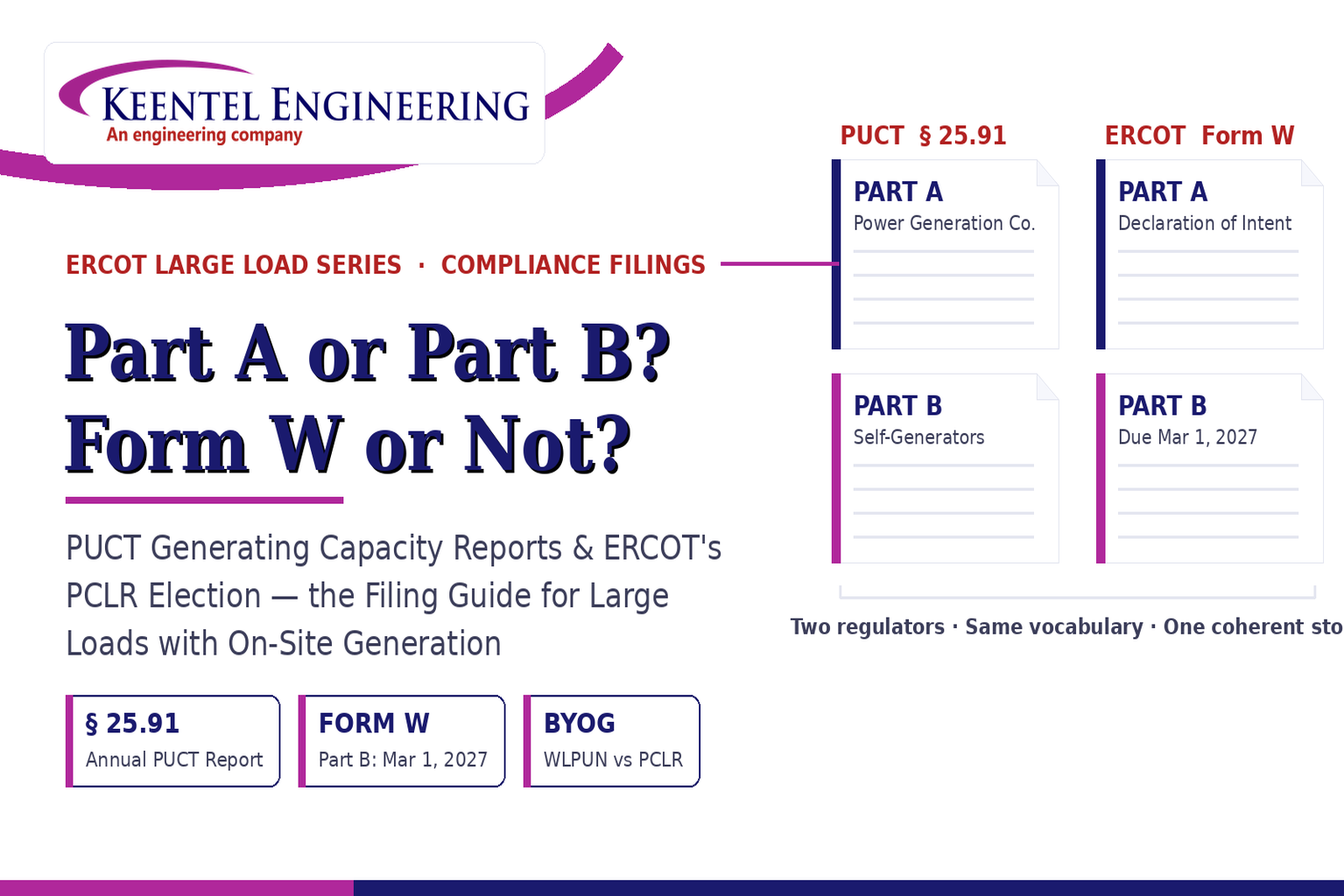
Learn the differences between the PUCT Generating Capacity Report and ERCOT Form W, including Part A vs Part B, PCLR, WLPUN, BYOG projects, and Batch Zero compliance.
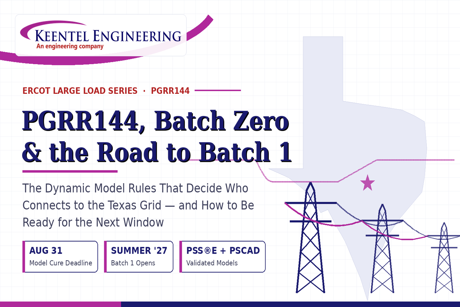
Learn how PGRR144, Batch Zero, and Batch 1 affect ERCOT large-load interconnections, dynamic model requirements, MQT testing, PERC1, and project readiness.
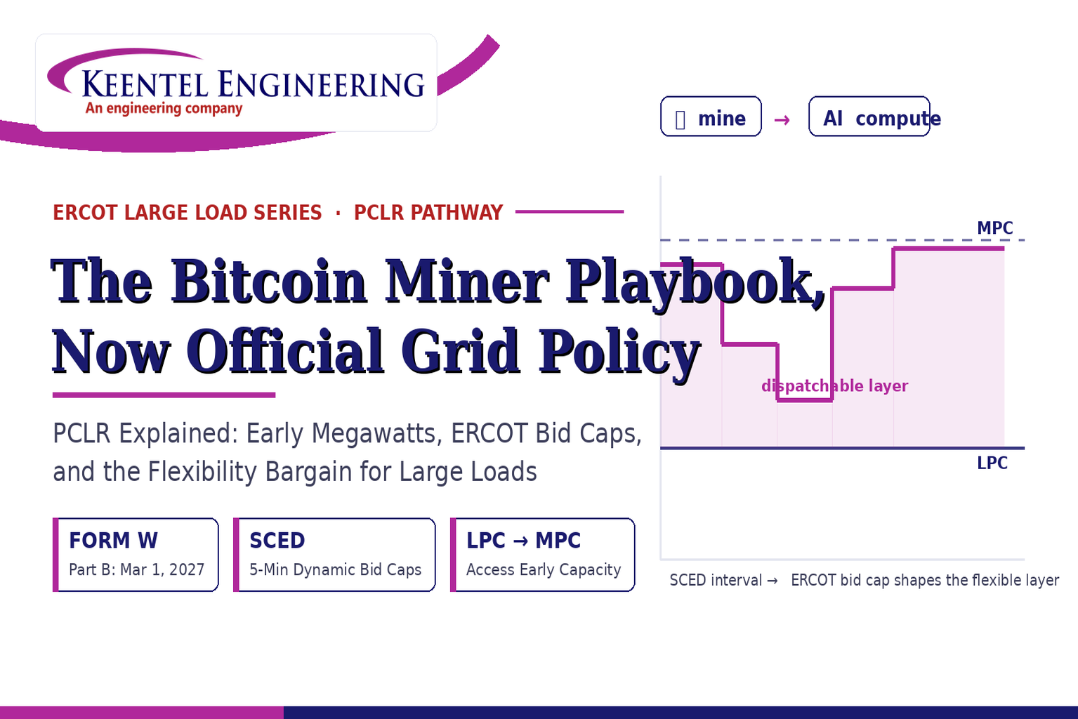
ERCOT PCLR Batch Zero large-load interconnection pathway
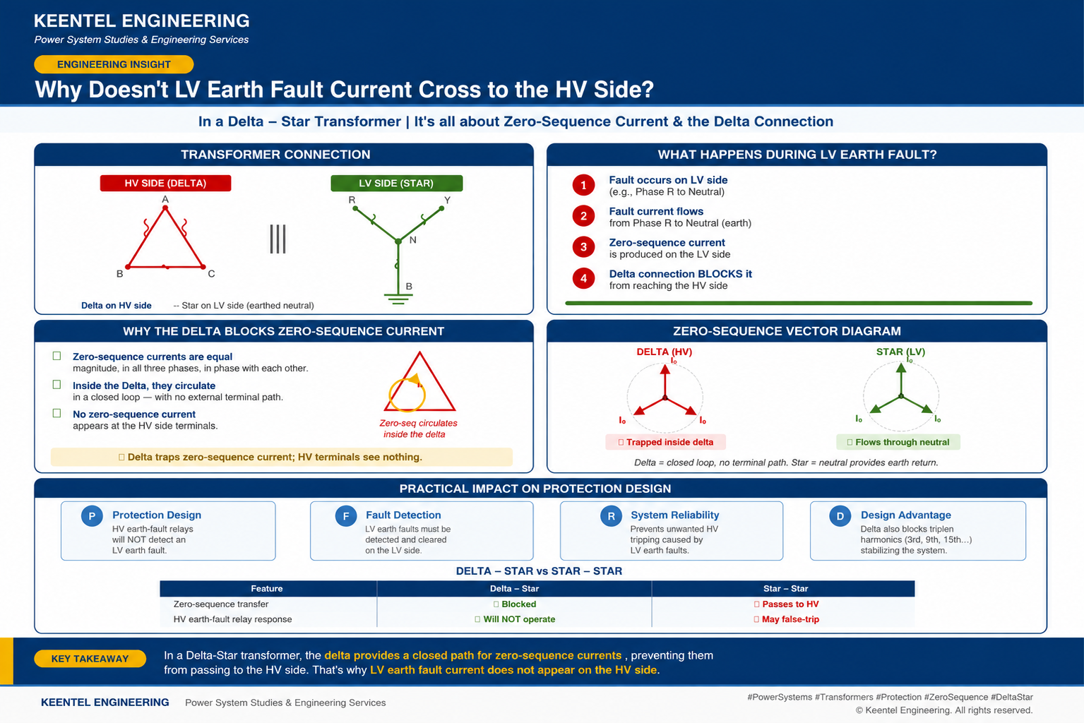
Learn why LV earth-fault current cannot cross a Delta-Star transformer, how zero-sequence current behaves, and what it means for protection design.

Learn how gas-insulated substations (GIS) improve safety, reliability, and space efficiency with 138 kV design, protection, insulation coordination, and real-world case studies.
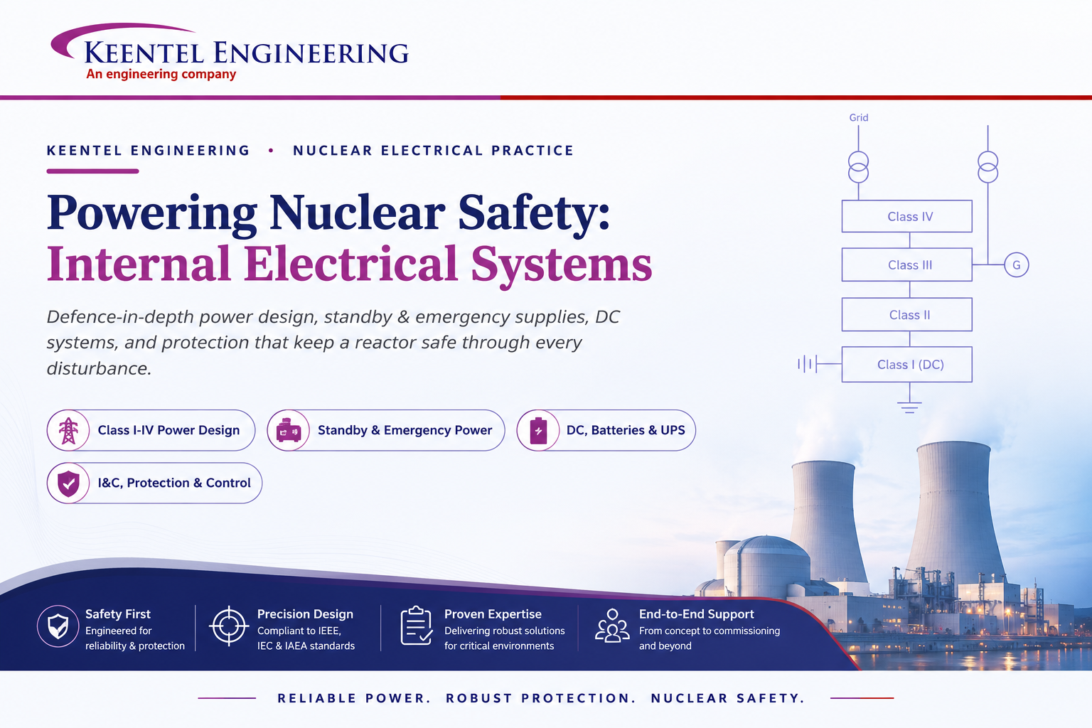
Learn how Class I–IV electrical systems, defence-in-depth, standby and emergency power, DC systems, protection, and load transfer ensure nuclear power plant safety.
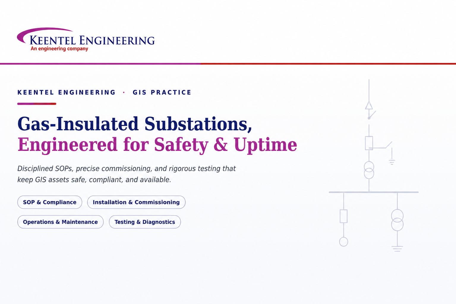
Learn GIS substation safety best practices, SOPs, commissioning, maintenance, interlocking, earthing, and testing to improve grid reliability and uptime.