A Coordinated Electric System Interconnection Review—the utility’s deep-dive on technical and cost impacts of your project.
Challenge: Frequent false tripping using conventional electromechanical relays
Solution: SEL-487E integration with multi-terminal differential protection and dynamic inrush restraint
Result: 90% reduction in false trips, saving over $250,000 in downtime
ERCOT enforces all of the above through simulation, which means your model is your compliance case. The bar is now high:
- Whole-facility scope. The model must represent everything the IT load, the UPS and power conversion, the cooling plant, the protection and control systems in formats compatible with ERCOT's study platforms (PSS/E, PSCAD, TSAT).
- Real control loops, not approximations. Generic textbook representations are unacceptable. The model must capture the actual inner control behavior of your power electronics.
- Hardware-validated converter models. For electronic loads, the PSCAD model must be benchmarked against actual hardware testing including voltage ride-through and subsynchronous response. A model assembled from standard PSCAD library blocks fails by definition, because a generic block has never been tested against your vendor's hardware. The good news: validation is a hardware-type test, so results for a given converter product are reusable across every facility that uses it.
- Format migration. Facilities that previously submitted the older composite load model (CMLD) format must transition to EPRI's PERC1 format.
- Three checkpoints. Models are reviewed before the stability study begins (no model, no study), before each quarterly stability assessment, and for electronic loads one final time before energization, when you must submit as-built models with a documented comparison against the previously studied data and a sworn attestation that the model matches actual field settings. ERCOT's review takes 10 business days, extendable by 20 put it on your critical path.
- A living obligation. Change your technology, controls, or relay settings in a way that affects ride-through including converting a crypto mining site to an AI data center — and you've triggered a new interconnection study, even if your megawatts don't change.
| Parameter | Detail |
|---|---|
| System | 230 kV / 138 kV transmission corridors, wind and wet-snow icing exposure |
| Data basis | 15 years of minute-resolution forced-outage records + regional weather observations |
| Core methods | Event grouping, MVA performance curves, time-to-95%-restore, area outage rate curves, fragility modeling, rerun-history benefits, exceedance and log-domain risk metrics |
| Headline result | ≈85% of maximum resilience benefit at 60% of original capital; worst-event restoration window cut from 11 days to 5 in rerun-history terms |
| Decision supported | Capital portfolio selection; resilience plan filing; post-investment verification framework |
| System / Topic | Governing Standard(s) | What It Controls |
|---|---|---|
| Overall plant electrical distribution | IEEE 141 (Red Book); IEEE 666 | Distribution architecture, voltage selection, design of generating station auxiliary service systems |
| Power system studies | IEEE 399 (Brown Book); IEEE 551 | Load flow, symmetrical/asymmetrical short circuit, motor starting methodologies down to the lowest LV panelboard |
| Protection & coordination | IEEE 242 (Buff Book); IEEE 3004.5; IEEE C37 series | Generator relaying (21, 59N, 87G), time-current coordination, selective clearing between LV and MV tiers |
| GSU / UAT / SST transformers | IEEE C57.12.00 and C57 family | Transformer ratings, impedance, testing, loading |
| HV switchyard breakers | IEEE C37.06 | AC high-voltage circuit breaker preferred ratings |
| MV switchgear (13.8 kV) | IEEE C37.20.2; IEEE C37.20.7 | Metal-clad construction, compartmentalization, vacuum breakers; arc-resistant design with plenum venting |
| MV cable | UL 1072; ICEA S-93-639 (NEMA WC 74) | Type MV-105 shielded cable, 133% insulation level for HRG systems |
| LV switchgear (480 V) | IEEE C37.13; UL 1558 | Metal-enclosed LV power circuit breaker switchgear to 635 V, draw-out ACBs with electronic trip units |
| Motor control centers | UL 845; NEMA ICS 18 | LV-MCC construction, MCCB/MCP protection for motors under ~200 HP |
| Motors | NEMA MG-1 | Motor performance, starting characteristics, service factors |
| DC & battery systems | IEEE 485; IEEE 946 | Lead-acid battery sizing (125/250 VDC), DC auxiliary system design |
| Grounding | IEEE 80; IEEE 142 (Green Book) | Ground grid step/touch potential limits; system grounding including high-resistance grounding |
| Lightning protection | IEEE 998 | Direct-stroke shielding of switchyard and outdoor generator structures |
| Arc flash & electrical safety | IEEE 1584; NFPA 70E | Incident energy calculation; worker safety boundaries and PPE |
| Fire protection | NFPA 850 | Fire protection and risk management for combustion turbine generating plants |
| Installation code | NEC (NFPA 70); NESC | Wiring methods inside the plant fence; overhead/outdoor clearances at the switchyard |
| Interconnection & compliance | FERC LGIP; NERC MOD-025/026/027, PRC-019/024/029, FAC-008 | Interconnection process, model validation, protection/ride-through coordination, facility ratings |
| IFC / Construction Deliverable | Purpose |
|---|---|
| Stamped IFC packages | Legal basis for construction; P.E. responsible charge |
| Final relay settings & TCCs | Protection as-installed matches the coordination study |
| Calculation archive | Owner records; NERC audit evidence trail |
| Commissioning procedures | Safe, sequenced energization; MOD field testing |
| Construction support | RFIs, field changes, FAT/SAT witness |
| As-builts & model handoff | Operating baseline; future study currency |
| Metric | Outcome |
|---|---|
| Defects found pre-occupancy | Three topology defects and one settings-mismatch family corrected before load migration; the shared-switchboard defect alone would have invalidated the concurrently-maintainable claim on day one |
| IST findings | Fourteen additional discrepancies surfaced under scenario testing (control logic, alarm mapping, one generator sequencing fault) — all closed before handover instead of during operations |
| Black-building test | Passed on second execution; the first attempt exposed the generator sequencing fault under true block load, exactly the failure the compressed plan would never have found |
| Handover quality | Operations team certified on the actual failure scenarios; corrected EOPs and settings documentation delivered as controlled documents |
| Business outcome | Occupancy proceeded three weeks behind the original date — against an independent estimate that the uncorrected sequencing fault carried a high probability of a full facility outage within the first year |
Part 2 — Frequently Asked Questions: Large Load Interconnection
An electric grid must remain in continuous balance — generation onto the grid must equal consumption from it at every instant. PJM achieves this balance, and prices it, through a layered market architecture. Each layer operates on a different time horizon, and each one touches project economics differently.
Substation Primary Design: A Complete Guide for Electrical Engineers
Jul 17, 2026 | Blog
1. What Is Substation Primary Design?
Substation primary design is the discipline responsible for the physical, high-voltage side of a substation: selecting, sizing, and arranging the heavy electrical equipment that actually carries power. It answers the questions that determine whether a substation is safe, reliable, constructible, and economical — which transformer, which breakers, what bus configuration, how much space between phases, how the ground grid dissipates fault current, and how the station survives lightning, wind, ice, and seismic events.
Every substation exists for one fundamental reason: voltage transformation and switching. Power is generated at medium voltage, stepped up for efficient long-distance transmission, and stepped down in stages for subtransmission, distribution, and finally utilization. Substations are the nodes where those transitions happen, and where utilities gain the ability to isolate equipment, reroute power, and protect the grid during faults. Primary design defines the hardware that makes all of that physically possible.
The primary design engineer owns the general arrangement (plan and elevation views), major equipment specifications, bus and insulator sizing, structural loading, grounding grid, lightning shielding, insulation coordination, and the clearances that keep energized parts safely separated from each other, from ground, and from people. Done well, primary design produces a station that passes every safety study, fits the site, accommodates future expansion, and minimizes installed cost. Done poorly, it produces change orders, failed studies, schedule slips, and — in the worst case — real safety hazards.
Keentel Insight
Primary design decisions are leverage decisions. A bus configuration chosen in week one drives breaker count, structure count, foundation quantities, protection schemes, and O&M flexibility for the next 40+ years. The cheapest time to optimize a substation is before the first drawing is issued.
2. Primary vs. Secondary Design: Brawn and Brains
A complete substation engineering package has two halves. Primary design is the “brawn” — the high voltage hardware and the mechanical and electrical physics that govern it. Secondary design is the “brains” — the protective relays, control circuits, SCADA, communications, and the AC/DC auxiliary systems that tell the primary equipment when to operate and keep the station alive during outages. The two disciplines are deeply interdependent: the primary one-line determines what must be protected; instrument transformer selection feeds relay settings; the DC battery must be sized to trip the very breakers the primary engineer selected.
| Scope | HV equipment, bus, structures, layout | Relays, controls, SCADA, communications |
|---|---|---|
| Key drawings | One-line, general arrangement, elevations, grounding plan, lightning shielding overlay | Three-lines, schematics, wiring diagrams, panel layouts, points lists |
| Governing physics | IEEE 80, IEEE 605, IEEE 998, IEEE 1427, ANSI C29, NESC, ANSI C84.1 | IEEE C37 series, IEEE 485, IEEE 1818, IEC 61850, DNP3, NERC PRC/CIP |
| Typical equipment | Transformers, breakers, switches, bus, arresters, CTs/CCVTs, steel structures | Relay panels, RTU/RTAC, batteries & chargers, HMI, network gear |
| Capacity Market (RPM) | Three years forward (tariff design) | Base Residual Auction plus incremental auctions procure committed capacity by location, with penalties for non-performance |
| Failure consequence | Flashover, structural failure, unsafe touch/step voltage | Misoperation, failure to trip, loss of visibility |
This guide focuses on the primary side, but it flags the interface points — instrument transformers, station service, and DC tripping capacity — where primary decisions constrain the secondary package. Coordinating both under one engineering roof eliminates the most common source of substation rework: primary and secondary packages that were developed in isolation and don’t reconcile.
3. U.S. Voltage Classes Every Substation Engineer Must Know
U.S. substations are designed around standardized nominal system voltages (ANSI C84.1 for systems up to 230 kV and companion practice for EHV). Each nominal voltage carries a maximum system voltage that equipment must withstand continuously, plus standardized insulation levels (BIL). Primary design starts by locating the project on this ladder, because voltage class drives clearances, insulator selection, bus sizing, structure heights, and cost.
| Low voltage (LV) | 0.120/0.240, 0.208, 0.480, 0.600 | ≤ 0.635 | Station service, auxiliary power, control buildings |
|---|---|---|---|
| Medium voltage / distribution | 2.4, 4.16, 4.8, 6.9, 12.47, 13.2, 13.8, 20.8, 22.9, 24.94, 27.6, 34.5 | up to 36.5 | Distribution feeders, collector systems for solar/wind/BESS, industrial plants |
| Subtransmission | 34.5, 46, 69 | 36.5 / 48.3 / 72.5 | Regional delivery, large industrial and municipal supply |
| High voltage (HV) | 115, 138, 161, 230 | 121 / 145 / 169 / 242 | Bulk transmission, generator interconnection, large load service |
| Extra-high voltage (EHV) | 345, 500, 765 | 362 / 550 / 800 | Backbone bulk power transfer across regions |
| Ultra-high voltage (UHV) | 1,100 (studied) | 1,200 | Not in commercial U.S. service; research and long-term |
A few practical notes. Distribution substations most commonly transform 69–138 kV down to 12.47, 13.2, 13.8, 24.94, or 34.5 kV. Renewable collector substations typically step 34.5 kV collector voltage up to 115, 138, 230, or 345 kV at the point of interconnection. The 161 kV class is regionally concentrated; 115 vs. 138 kV prevalence also varies by utility footprint. EHV work at 345/500/765 kV introduces additional considerations — corona and audible noise, switching surge control, shield wire and insulation coordination refinements — that materially change the primary design approach.
Keentel Insight
Design to maximum system voltage, not nominal. A “138 kV” substation is really a 145 kV substation for insulation, clearance, and arrester duty purposes. Treating nominal voltage as the design voltage is one of the most common errors we correct in third-party design reviews.
4. Bus Configurations: Reliability vs. Cost
The bus configuration is the single most consequential primary design decision. It sets breaker count, physical footprint, operating flexibility, and the outage consequences of any single failure. The five arrangements below cover the vast majority of U.S. practice.
4.1 Single Breaker, Single Bus
The simplest arrangement: one common bus, one breaker per circuit. It is inexpensive and compact, but a bus fault or breaker maintenance takes the entire station out of service. Widely used at distribution voltage; limited use at HV except for small or radial stations. Adding a bus sectionalizing breaker improves flexibility at modest added cost.
4.2 Main and Transfer Bus
A normally de-energized transfer bus parallels the main bus, allowing any one breaker to be bypassed for maintenance while its circuit stays in service through a transfer scheme. Common in outdoor distribution and legacy subtransmission stations. Protection complexity increases because relaying must follow the transferred circuit.
4.3 Ring Bus
Breakers are connected in a closed loop with circuits tapped between breakers; there is no bus section per se. Every circuit is served by two breakers, so any single breaker can be maintained without a circuit outage, and a bus-section fault removes only the adjacent elements. The ring is a popular HV choice for four-to-six-terminal stations and converts naturally into a breaker-and-a-half arrangement as the station grows — which is why many utilities specify a ring “with B&AH expansion provisions” on day one.
4.4 Breaker-and-a-Half
Two main buses with three breakers per two circuits (“a breaker and a half” per circuit). Any breaker or either bus can be removed from service without dropping a circuit, and the arrangement tolerates certain double contingencies. It is the workhorse of U.S. EHV and critical HV stations, generator interconnections, and large load-serving hubs.
4.5 Double Breaker, Double Bus
Two breakers and two buses per circuit; all breakers normally closed. Maximum operating flexibility and security — and maximum cost. Reserved for the most critical nodes: major generating plant switchyards and system-critical EHV hubs.
4.6 Relative Installed Cost
Industry benchmarking places the arrangements on a consistent relative cost scale (single breaker/single bus = 100%):
| Single breaker – single bus | 100% (120% with sectionalizing breaker) | Bus fault or breaker work drops the whole station |
|---|---|---|
| Ring bus | 125% | No circuit outage for breaker maintenance; degraded ring during work |
| Main and transfer bus | 140% | Breaker bypass without circuit outage; bus fault drops station |
| Breaker-and-a-half | 145% | No circuit outage for any breaker or single bus outage |
| Double breaker – double bus | 190% | Highest security; tolerates bus + breaker contingencies |
The right choice balances the criticality of the connected circuits against capital budget and site area. For a typical HV interconnection with four terminals, a ring bus captures most of the reliability benefit at a fraction of the breaker-and-a-half cost — provided the layout genuinely reserves space, foundations, and bus geometry for the future conversion.
5. AIS vs. GIS: Choosing the Insulation Medium
Air-insulated substations (AIS) use atmospheric air as the primary insulation between phases and to ground, which makes clearances — and therefore land area — the dominant layout driver. Gas-insulated switchgear (GIS) encloses bus, breakers, and switches in grounded metal enclosures filled with an insulating gas, compressing an entire switchyard into a fraction of the footprint, indoors or out.
| Footprint | Large; driven by phase spacing and clearances | Roughly 10–25% of equivalent AIS area |
|---|---|---|
| Capital cost | Lower equipment cost | Higher equipment cost; often offset by land and civil savings |
| Environment | Exposed to contamination, wildlife, weather | Sealed; suited to coastal, desert, urban, and seismic sites |
| Maintenance | More frequent; components individually accessible | Low frequency; specialized skills and OEM support required |
| Expansion / repair | Straightforward bay additions | Requires gas handling and longer lead planning |
| Typical use | Rural and suburban HV/EHV yards with available land | Urban infill, data center campuses, constrained or harsh sites |
Hybrid solutions (mixed-technology switchgear, or GIS at one voltage level and AIS at another) are increasingly common where land is tight but budgets do not support full GIS. The decision should be made early — it changes civil scope, structural scope, and the entire general arrangement.
6. The Core Primary Design Tasks
What follows is the working sequence Keentel applies on substation primary design engagements, with the governing standards and representative calculations an electrical engineer should be able to reproduce.
6.1 Major Equipment Sizing
Equipment sizing begins with the power transformer, because everything else — breaker ratings, bus ampacity, fault duty, foundation loads — cascades from it.
Transformer MVA
For a three-phase transformer, apparent power follows S = √3 × VL × IL. As a representative example: a 115 kV circuit expected to carry 600 A requires √3 × 115 kV × 600 A ≈ 119.5 MVA of capacity. Modern power transformers carry staged nameplate ratings — for example 95/127/158 MVA — corresponding to self-cooled operation (ONAN) and one or two stages of forced-air cooling (ONAF). The base (ONAN) rating anchors impedance and fault calculations; the top forced-cooled rating defines maximum continuous loading and drives the ratings of everything downstream.
Circuit Breaker and Switch Continuous Ratings
Breakers and disconnect switches are selected for the maximum load they must carry with margin. A common utility practice applies a 125% factor to the maximum transformer rating: I = 1.25 × S / (√3 ×
Interrupting Capacity (kAIC)
Every breaker must interrupt the maximum fault current at its location. A first-pass screen uses the infinite-bus approximation through the transformer impedance: ISC = Sbase / (√3 × VL × Z%). For a 95 MVA base transformer at 10% impedance feeding a 34.5 kV secondary: 95 / (√3 × 34.5 × 0.10) ≈ 15.9 kA — specify the next standard interrupting class (25 kA) with margin for system contribution and future growth. The infinite-bus screen is conservative on the transformer contribution but ignores source impedance and motor/inverter contribution; a proper short-circuit study (which Keentel performs in every engagement) supersedes it before equipment is purchased.
Instrument Transformers
Current transformers are sized with the primary winding at or above full load current and a 5 A secondary in U.S. practice (typical ratios 600/5, 1200/5, 2000/5, 3000/5), then verified with the protection engineer for burden, accuracy class, and saturation under maximum fault. Potential transformers and CCVTs use line-to-ground primary ratings with a 115 V-class secondary; at HV, CCVTs
dominate for economy and double as carrier coupling points. Ratio and BIL selections must match the system voltage class table in Section 3.
Surge Arresters
Arrester selection starts from maximum continuous operating voltage (MCOV): the arrester must continuously withstand the maximum line-to-ground voltage for the system grounding configuration. Effectively grounded (multi-grounded) systems permit lower MCOV values than impedance-grounded, ungrounded, or delta systems, where temporary overvoltages during ground faults approach line-to-line voltage. Station-class arresters located at line entrances and at the transformer are the first line of the insulation coordination strategy in Section 6.5.
6.2 General Arrangement, Phase Spacing, and Clearances
The general arrangement (GA) is the master document of primary design: a dimensioned plan view locating every major piece of equipment, the control building, bus runs, structures, and the perimeter fence, with elevation sections cut through each significant axis. Clearance requirements govern the geometry: phase-to-phase and phase-to-ground spacing per voltage class, safety working clearances, and equipment access. The governing references are the NESC, IEEE 1427 (electrical clearances in substations), ANSI C29 insulator standards, NFPA 70E for working spaces, and — critically — the owner’s own standards, which frequently exceed code minimums. Representative HV practice: on the order of 8- foot phase centers at 138 kV rigid bus versus 6-foot at 69 kV, with clearances re-verified against elevation changes, equipment bushing geometry, and conductor movement.
Good GA practice that separates a professional layout from a code-minimum one: centralize the control building to shorten every cable run while honoring minimum standoff from the transformer (a common utility rule is 60 feet or a fire barrier, so a transformer failure cannot disable station controls); orient equipment terminal boxes toward the cable trench; place dead-end (termination) structures near
6.3 Bus Design: Rigid, Strain, and Short-Circuit Forces
Substations use two bus constructions. Rigid bus — typically schedule aluminum pipe on station post insulators (representative practice: 4-inch Schedule 80 at 138 kV, 3-inch Schedule 40 at 69 kV) — offers clean phase spacing, low sag, and easy equipment connections. Strain bus — flexible conductor strung between dead-end structures — spans long distances economically and connects termination towers into the yard. Most stations combine both.
Bus and insulator sizing per IEEE 605 must satisfy three simultaneous demands: ampacity (continuous current with allowable temperature rise), short-circuit mechanical forces (electromagnetic forces between phases during faults scale with the square of current and inversely with spacing, loading both the bus and the insulator cantilever ratings), and structural loading (wind, ice, and where applicable seismic per the owner’s criteria and ASCE guidance). Span lengths, fitting selection, and aeolian vibration dampers fall out of the same calculation set. Undersized insulator cantilever strength under fault forces is a classic review finding.
6.4 Structural and Civil Interface
Primary design defines the loading trees that structural engineers use to design steel and foundations: dead-end structure tensions from incoming spans, equipment weights and operating loads, bus short circuit reactions, and wind/ice/seismic combinations. H-frame termination structures deserve early attention — they carry full line tension as dead-ends, need substantial foundations, and their placement fixes the line approach geometry for the life of the station. Oil containment for the transformer, drainage, roads for transformer delivery (a 158 MVA unit is a superload), and fence grounding integration complete the civil interface.
6.5 Insulation Coordination
Insulation coordination matches the withstand strength of every insulation element — bushings, insulators, air gaps, transformer windings — against the overvoltage stresses the station will see: lightning surges, switching surges (dominant at EHV), and temporary overvoltages. The toolkit: standardized BIL selection per voltage class, station-class surge arresters at line entrances and transformer terminals positioned within protective distance limits, shield wires and masts to intercept direct strokes (Section 6.7), and at EHV, closing resistors or controlled switching. The deliverable is a coordinated set of BILs and arrester ratings demonstrating protective margins per IEEE C62 practice.
6.6 Grounding Grid Design (IEEE 80)
The grounding system is a life-safety system. During a ground fault, thousands of amperes flow into the earth through the grid, elevating the station ground potential. IEEE 80 defines the two human exposure limits the design must satisfy: touch voltage (hand on grounded structure, feet on soil) and step voltage (one-meter stride on the surface). The workflow:
• Soil resistivity measurement. The Wenner four-point method — four equally spaced electrodes, outer pair injecting current, inner pair measuring voltage — produces apparent resistivity versus probe spacing. Representative sites show strong layering: e.g., ~125 Ω·m near the surface dropping to ~22 Ω·m in a mid-layer, rising again at depth.
• Soil modeling. Field data is fit to a multi-layer soil model in specialized software. The layer structure tells the designer which stratum should collect fault current — grid depth and ground rod length are chosen to reach the low-resistivity layer (e.g., grid at 18 inches with 10-foot rods penetrating a conductive second layer).
• Conductor sizing. Minimum conductor area follows the IEEE 80 fusing equation from maximum grid fault current and clearing time. A representative case — 21 kA single-phase-to-ground, 0.5 s clearing, soft-drawn copper — yields roughly 104 kcmil minimum; 4/0 AWG stranded copper (211.6 kcmil) is the common conservative selection.
• Safety limits. Tolerable touch and step voltages are computed from body mass criteria, fault duration, and the surface layer. A 4-inch crushed-rock layer at ~3,000 Ω·m dramatically raises tolerable limits (representative values: ~672 V touch, ~2,220 V step) by increasing foot contact resistance.
• Iterative optimization. The grid is modeled, checked against limits, and the mesh spacing widened (or tightened) iteratively. Starting from a conservative 30-foot mesh and relaxing in 10-foot steps until the first failure brackets the optimum — a representative design passed at 70-foot spacing and failed at 80 — converts directly into copper savings without sacrificing safety.
• System checks. The grid extends about 3 feet beyond the fence (which is bonded), every structure and equipment tank ties to the grid, and total grid impedance is verified — well under the common 2 Ω industry threshold for transmission stations (representative result: 0.19 Ω).
Keentel Insight
Optimization is where grounding engagements pay for themselves. Widening a compliant grid from 30- foot to 70-foot mesh across a 400 × 400-foot yard removes miles of buried copper and hundreds of exothermic connections from the bill of materials — routinely a six-figure construction saving on a study that costs a small fraction of that.
6.7 Lightning Shielding (IEEE 998)
Direct strokes to unshielded equipment are among the few events that can destroy a transformer outright. IEEE 998 provides the design methods — the electrogeometric model (EGM) and the empirical curves method — for placing shield wires and lightning masts so every critical component sits inside a zone of protection. In the empirical-curves workflow, the designer computes the ratio of protected equipment height (d) to mast height (h), enters the exposure curve (typically the 0.1% curve for station work), reads the x/h ratio, and solves for the protective radius x of each mast. A second family of curves gives s/h — the maximum separation at which adjacent zones of protection reinforce
6.8 The Auxiliary System Interface
Two auxiliary systems sit at the boundary between primary and secondary design, and the primary engineer must leave room — physically and electrically — for both. The 125 V DC system (station battery and charger, sized per IEEE 485) must trip and close the breakers the primary engineer selected: trip coils, close coils, and spring-charging motors define the momentary duty; relays, annunciators, and DC lighting define the continuous duty. Correct practice sizes the battery against a worst-case fault scenario duty cycle — a first-minute momentary block, a continuous block, and an end-of-duty momentary block — not a naive sum of every load. The AC station service system (per IEEE 1818, the industry guide for low-voltage auxiliary systems) supplies transformer cooling, breaker and CT/PT heaters, HVAC, lighting, receptacles, and battery charging, tabulated with load and demand factors. Station service transformer sizing, redundancy philosophy, and control building space for panels and batteries are all reserved during primary layout.
7. The Design Milestone Progression: 30% → 60% → 90% → IFC
U.S. substation projects advance through standardized review gates. Each gate has an expected content level, and disciplined milestone management is what keeps a substation package reviewable, biddable, and buildable.
| 30% (Preliminary) | One-line, preliminary GA plan, equipment list, bus configuration decision, site sizing, preliminary grounding & lightning concepts | Lock the big decisions: configuration, footprint, major equipment |
|---|---|---|
| 60% (Detailed) | Dimensioned GA and elevations, grounding study & plan, lightning shielding study, bus calcs, structural loading trees, equipment specifications issued | Enable long-lead procurement and structural/civil design |
| 90% (Check) | All drawings essentially complete, calculations finalized, vendor data incorporated, interdisciplinary check complete | Constructability and owner review; only comments remain |
| IFC (Issued for Construction) | Stamped drawing package, final calculations, bill of materials, construction notes | Build it |
Peer review is embedded at every gate: drafter, independent checker, and reviewing engineer, with revision clouding so every change between milestones is visible. First drafts fail review — that is the point of the process. Representative first-pass findings on real projects include incorrect phase spacing carried between voltage levels, missing surge arresters at line entrances, missing bus transitionstructures between elevation levels, and extra or missing CCVTs — all inexpensive to fix on paper and expensive to fix in steel.
8. Governing Standards Quick Reference
| ANSI C84.1 | Standard nominal and maximum system voltages (through 230 kV) and voltage ranges |
|---|---|
| IEEE 80 | AC substation grounding — touch/step limits, conductor sizing, grid design |
| IEEE 81 | Measurement of earth resistivity and ground impedance |
| IEEE 605 | Rigid bus structural and electrical design, short-circuit forces |
| IEEE 998 | Direct lightning stroke shielding of substations (EGM / empirical curves) |
| IEEE 1427 | Electrical clearances in substations |
| IEEE 1818 | Design of AC/DC low-voltage auxiliary systems for substations |
| IEEE 485 | Sizing lead-acid station batteries |
| IEEE C57 series | Power transformers — ratings, testing, loading |
| IEEE C37 series | Circuit breakers, switchgear, and protective relaying |
| IEEE C62 series | Surge arresters and insulation coordination application |
| ANSI C29.8 / C29.9 | Wet-process porcelain and toughened glass insulators |
| NESC (ANSI C2) | National Electrical Safety Code — clearances, grounding, safety rules |
| NFPA 70E | Electrical safety in the workplace — working clearances and arc flash |
| ASCE 113 | Substation structure design guide (loading, deflection) |
9. How Keentel Engineering Assists
Keentel Engineering LLC is a U.S. power systems and grid interconnection consulting firm delivering substation primary design as an integrated package with the studies that validate it. Our engineers hold P.E. licensure and IEEE senior membership, and our deliverables are built to utility review standards from the first submittal.
Full-Scope Substation Primary Design
• One-line and three-line development; bus configuration selection studies with cost/reliability tradeoff analysis
• General arrangement plans, elevation sections, and clearance verification at every U.S. voltage class — distribution (2.4–34.5 kV), subtransmission (34.5–69 kV), HV (115–230 kV), and EHV (345– 765 kV)
• Major equipment sizing and specification: transformers, breakers, switches, instrument transformers, arresters
• Rigid and strain bus design with IEEE 605 ampacity and short-circuit force calculations • Structural loading trees, dead-end structure coordination, and civil interface packages
Safety and Performance Studies
• IEEE 80 grounding studies with soil modeling, touch/step analysis, and copper-optimized grid design
• IEEE 998 lightning shielding studies with mast/shield-wire optimization
• Short-circuit, load flow, insulation coordination, cable ampacity, and arc flash studies • AC/DC auxiliary system design: IEEE 485 battery sizing, IEEE 1818 station service design
Program-Level Support
• 30/60/90/IFC milestone management with embedded QA/QC and independent checking • Owner’s engineer and third-party design review for utilities, developers, and EPCs
• Grid interconnection engineering — POI selection, interconnection studies, EMT modeling, and NERC compliance — so the substation and its interconnection requirements are engineered together, not sequentially
10. Conclusion
Substation primary design is where electrical physics, mechanical engineering, safety science, and construction economics converge on a single set of drawings. The engineer who masters the sequence — voltage class, bus configuration, equipment sizing, general arrangement, bus and structural design, insulation coordination, grounding, and lightning shielding — controls the cost, safety, and 40-year flexibility of the asset. The engineer who treats those tasks as isolated checklist items inherits the change orders.
Keentel Engineering brings the full sequence under one roof, backed by the
power system studies that validate every selection. If you are planning a substation at any U.S. voltage class — or inheriting one that needs a second set of eyes — we would welcome the conversation.
Case Study 1: Grounding and Lightning Optimization for a 138/69 kV Renewable Interconnection Substation
| Facility type | Greenfield ring bus interconnection substation for utility-scale wind generation |
|---|---|
| Voltage class | 138/69 kV (HV / subtransmission) |
| Configuration | Three-breaker 138 kV ring bus, 138/69 kV power transformer, single 69 kV line exit; breaker-and-a-half expansion provisions |
| Keentel scope | IEEE 80 grounding study and grid design, IEEE 998 lightning shielding study, physical design support |
The Challenge
A renewable energy client required a new interconnection substation delivering wind generation into the transmission system. The site was fixed at 400 × 400 feet to accommodate future expansion, and the owner’s mandate was explicit: full IEEE 80 safety compliance and complete IEEE 998 lightning coverage at the minimum installed cost. Layered soil conditions complicated the grounding problem — field resistivity ranged from roughly 125 Ω·m near the surface down to the low 20s in a mid-layer before rising again at depth — and the worst-case single-phase grid fault was established at 21 kA with 0.5- second clearing.
Keentel’s Approach
Grounding came first, because the grid boundary defines the buildable area. Wenner four-point field data was fit to a multi-layer soil model, which showed the second stratum offering the lowest resistivity path. The grid was therefore set 18 inches below grade with 10-foot ground rods driven to terminate inside that conductive layer — deliberately steering fault current where the earth dissipates it best.
Conductor sizing per the IEEE 80 fusing equation returned a minimum of roughly 104 kcmil for soft drawn copper at the design fault; 4/0 stranded copper was selected for conservatism and mechanical durability, extended 3 feet beyond the fence line with the fence bonded to the grid. Tolerable limits were then established with a 4-inch, 3,000 Ω·m crushed rock surface layer: approximately 672 V touch and 2,220 V step.
The optimization was systematic. A deliberately conservative 30-foot mesh established the safe baseline — and also demonstrated, in a no-surface-layer sensitivity run, that the crushed rock layer was essential (localized touch potentials exceeded limits without it). Mesh spacing was then relaxed in 10-foot increments with full touch/step re-analysis at each step. The design passed at 70-foot spacing with the touch result inside 30 V of the limit — a precisely engineered margin — and failed at 80 feet, bracketing the optimum. Final grid impedance computed at 0.19 Ω against the 2 Ω industry threshold.
The Outcome
- Mesh optimization from 30-foot to 70-foot spacing removed more than half the buried copper runs and associated exothermic connections from the bill of materials — a six-figure construction saving — with every configuration verified compliant
- Grid impedance of 0.19 Ω, an order of magnitude inside the 2 Ω threshold
- Lightning mast count reduced through zone-interaction analysis with full IEEE 998 coverage documented
- Grounding boundary and mast placement coordinated with the dashed-in future breaker-and-a half bay, so the expansion inherits a compliant foundation rather than a retrofit
Case Study 2: General Arrangement and Bus Design for a 345/138 kV Breaker-and-a-Half Transmission
| Facility type | Greenfield ring bus interconnection substation for utility-scale wind generation |
| Voltage class | 138/69 kV (HV / subtransmission) |
| Configuration | Three-breaker 138 kV ring bus, 138/69 kV power transformer, single 69 kV line exit; breaker-and-a-half expansion provisions |
| Keentel scope | IEEE 80 grounding study and grid design, IEEE 998 lightning shielding study, physical design support |
The Challenge
A transmission owner needed a new EHV station where reliability requirements ruled out any configuration that could drop a circuit for breaker maintenance — driving the 345 kV yard to a breaker and-a-half arrangement, at roughly 145% of single-bus relative cost, with every dollar of that premium requiring justification through layout efficiency. High available fault duty stressed bus short-circuit forces; the corridor’s wind and ice loading criteria stressed structures; and the owner’s standards exceeded code-minimum clearances at both voltage levels. The station also had to accept two future 345 kV line terminals without rework.
Keentel’s Approach
The 30% package locked the decisions with the longest shadows: bay ordering that placed the autotransformers on adjacent diameters (limiting bus runs between them), a centralized control building honoring the transformer standoff rule, and dead-end structures positioned so both existing and future line approaches never cross major equipment. The future terminals were drawn dashed with their foundations, bus stubs, and ground grid extensions fully dimensioned — reserved in steel-ready detail, not as a note.
Bus design proceeded under IEEE 605. At 345 kV, ampacity was straightforward; short-circuit mechanical force governed. Phase-to-phase electromagnetic forces at the design fault were computed against candidate spans and schedules, iterating span length, pipe schedule, and insulator cantilever class together until the system carried fault forces with the owner’s required margin — including the simultaneous wind case. Strain bus tensions into the dead-end structures fed the structural loading trees along with wind, ice, and equipment operating loads, giving the structural discipline a complete, revision-controlled loading basis at 60%.
Insulation coordination matched arrester MCOV to the effectively grounded system at both voltage levels, verified protective margins between arrester protective levels and equipment BIL (including separation-distance effects for equipment remote from arresters), and documented switching-surge considerations appropriate to the 345 kV class. Elevation sections were cut through every distinct bus
substation-design Technical Guide
level, with transition structures resolving the height changes between the 345 kV and 138 kV work — the detail most often missed in first-pass elevation drafting.
The package moved through 30/60/90/IFC with independent checking at each gate and clouded revisions between submittals. Owner review comments at 60% — principally vendor-data-driven bushing geometry updates and a request to lengthen one maintenance access corridor — were incorporated and re-checked without milestone slip.
The Outcome
- IFC package delivered on schedule with zero clearance or spacing comments at the 90% owner review
- Breaker-and-a-half premium partially recovered through layout efficiency: compact bay ordering and shared lightning masts on dead-end structures reduced steel and foundation count versus the owner’s reference layout
- Future line terminals fully reserved — foundations, bus geometry, grounding — enabling later expansion with no rework of the energized yard
- Complete structural loading trees accepted by the structural engineer of record without a single reissue cycle
Case Study 3: Fast-Track Equipment Sizing and Auxiliary Design for a 115/34.5 kV Solar-Plus-Storage Collector Substation
| Facility type | Collector step-up substation for a utility-scale solar and battery energy storage facility |
| Voltage class | 115/34.5 kV (HV / medium-voltage collector) |
| Configuration | Single 115 kV line terminal, main power transformer with staged cooling, 34.5 kV collector bus |
| Keentel scope | Major equipment sizing, one-line development, arrester and instrument transformer selection, IEEE 485 DC and IEEE 1818 AC auxiliary system design, IFC support on a compressed schedule |
The Challenge
A renewable developer faced a contractual energization date that left no float for sequential engineering. Transformer and breaker specifications had to be issued for procurement before the layout was complete, meaning every rating had to be right the first time — in an inverter-based-resource environment where fault contribution behaves differently than conventional generation and auxiliary reliability directly affects revenue.
Keentel’s Approach
Equipment sizing was executed as a front-loaded calculation package. The main transformer was sized from interconnection capacity using S = √3 × VL × IL and specified with staged ONAN/ONAF/ONAF ratings so the base rating anchored fault and impedance studies while the top rating carried maximum plant output with margin. The 115 kV breaker continuous rating applied the 125% practice to the transformer’s top rating and selected the next standard class; interrupting duty was screened with the infinite-bus method through the transformer impedance, then confirmed with a short-circuit study incorporating utility source data and documented inverter fault contribution — the screen and the study were both filed, giving the owner a defensible margin narrative.
Arresters were selected by MCOV for the effectively grounded 115 kV system and the collector-side grounding configuration, coordinated against equipment BIL per voltage class. CTs were specified at full load-plus-margin primary ratings with 5 A secondaries, ratio-verified with the protection engineer for burden and saturation; the 115 kV terminal used CCVTs, ratio-matched to the line-to-ground system voltage with a 115 V-class secondary.
The auxiliary systems were engineered in parallel rather than as an afterthought. DC loads were inventoried from vendor catalog data — trip and close coils, breaker spring-charging motors, lockout relays, protective relays, annunciators, and DC emergency lighting — and the battery was sized per IEEE 485 against a worst-case fault scenario duty cycle: a first-minute momentary block capturing the fault event, an eight-hour continuous block for the station-service-outage case, and an end-of-duty momentary block proving the battery could still charge springs and operate breakers at the end of discharge. Charging motors were conservatively modeled at a two-minute run to envelope starting current. The AC station service load tabulation per IEEE 1818 applied load and demand factors across yard, power distribution center, and control building loads — transformer cooling, equipment heaters, HVAC, lighting, receptacles, fire alarm, and battery charging — sizing the station service supply with documented diversity rather than raw connected load.
The Outcome
- Long-lead transformer and breaker specifications issued weeks ahead of layout completion with zero subsequent rating revisions
- Battery sizing withstood owner’s-engineer review without modification — the duty-cycle methodology and simulation-backed voltage profile answered every question in the first response cycle
- Documented kAIC margin narrative (screen plus full study) accepted by the interconnecting utility without follow-up data requests
- Substation energized on the contractual date; the auxiliary design basis was reused by the developer as a fleet template for subsequent collector stations
Frequently Asked Questions
1. What exactly does “primary design” include, and where does it stop?
Primary design covers the high-voltage power path and its physical world: one-lines, general arrangement, major equipment selection and sizing, bus design, clearances, structures interface, grounding, lightning shielding, and insulation coordination. It hands off to secondary design at the instrument transformer secondaries and the control building door — relaying, control wiring, SCADA, and communications are secondary scope, though the two must be coordinated continuously.
2. How is the bus configuration chosen for a new substation?
By balancing circuit criticality, outage tolerance, budget, and site area. A radial distribution station may justify only a single bus; a four-terminal HV interconnection typically lands on a ring bus with breaker and-a-half expansion provisions; critical EHV hubs and plant switchyards justify breaker-and-a-half or double-breaker/double-bus. Relative installed cost runs from 100% (single bus) to roughly 190% (double breaker), so the configuration decision is also the single largest cost lever in the station.
3. What U.S. voltage classes apply to substation work?
Distribution/medium voltage (2.4, 4.16, 12.47, 13.2, 13.8, 24.94, and 34.5 kV among others), subtransmission (34.5, 46, 69 kV), high voltage (115, 138, 161, 230 kV), and extra-high voltage (345, 500, 765 kV). Equipment is designed to the corresponding maximum system voltage (e.g., 145 kV for a nominal 138 kV system) per ANSI C84.1 and companion practice.
4. How do I size the power transformer?
Start from forecast load or interconnection capacity: S = √3 × VL × IL. Select a standard staged rating (ONAN/ONAF/ONAF) whose top rating covers maximum loading with margin and whose base rating sets your impedance and fault calculations. Then verify impedance against both fault duty (higher Z limits fault current) and voltage regulation (lower Z limits drop) — the two pull in opposite directions.
5. What is kAIC and why does it matter?
Kiloampere interrupting capacity — the maximum fault current a breaker can safely interrupt. Applying a breaker beyond its interrupting rating risks catastrophic failure. A quick infinite-bus screen (MVA base / (√3 × VL × Z%)) bounds the transformer contribution, but a full short-circuit study including source impedance and all contributions is required before purchase.
6. Why is the 125% factor applied to breaker continuous ratings?
It provides margin for emergency loading, unbalance, ambient temperature, and future growth, and it aligns the selection with standard rating steps (1,200 A, 2,000 A, 3,000 A). Individual utilities may specify different margins; the owner’s standard governs.
7. What determines phase spacing and clearances?
Voltage class (specifically maximum system voltage and BIL), governed by NESC, IEEE 1427, ANSI C29 insulator dimensions, NFPA 70E working space, and the owner’s standards — which frequently exceed code. Clearances must be verified in three dimensions, including conductor movement, equipment bushing geometry, and maintenance access, not just in plan view.
8. Why is grounding design iterative instead of formula-based?
Because the governing variables — layered soil resistivity, grid geometry, fault current division, and surface treatment — interact nonlinearly. Practice is to build a compliant conservative grid, then relax mesh spacing in steps until the touch/step limits bracket the optimum. The iteration converts directly into copper savings while every configuration is verified against IEEE 80 limits.
9. Does the crushed rock layer in a substation actually matter?
Enormously. A 4-inch layer of ~3,000 Ω·m crushed rock raises foot-to-earth contact resistance, which raises the tolerable touch and step voltages by hundreds of volts. Designs that fail without a surface layer routinely pass with one — it is one of the cheapest safety measures in the yard, and it must be maintained over the station’s life.
10. What is a zone of protection in lightning design?
The volume around a shield mast or wire inside which a direct lightning stroke is intercepted before reaching equipment, computed per IEEE 998 from mast height and protected equipment height. Adjacent zones interact: where masts are close enough, the combined protected area exceeds the sum of the individual circles, which is why optimized designs frequently need fewer masts than a first-pass layout.
11. AIS or GIS — how do we decide?
Land, environment, and lifecycle cost. If the site has room and a benign environment, AIS is usually cheapest. If land is constrained, the environment is coastal/contaminated/urban, or reliability requirements are extreme, GIS pays for itself in footprint and maintenance. Hybrid arrangements are common. Decide early — the choice restructures the entire layout and civil scope.
12. What does a complete primary design deliverable package contain?
One-line diagram, general arrangement plan and elevation sections, grounding study and grounding plan, lightning shielding study and overlay, bus and insulator calculations, structural loading trees, equipment specifications and data sheets, conduit/raceway plan interface, bill of materials, and construction notes — progressed through 30/60/90/IFC gates with independent checking at each.
13. How long does substation primary design take?
Scope-dependent, but representative durations for a straightforward HV station run several months from kickoff to IFC, with long-lead equipment specifications (transformer, breakers) issued at or before 60% to protect the schedule. Fast-track collector substations compress this by paralleling studies and layout; complex EHV stations extend it.
14. What information does Keentel need to start a primary design engagement?
The interconnection or load basis (MW/MVA, voltage class, terminal count), site survey and geotechnical/soil resistivity data if available (we can specify and coordinate the testing if not), the owner’s design standards, fault duty data or system model access, and any existing drawings for brownfield work. From that basis we produce a 30% package that locks the decisions everything else depends on.
About Keentel Engineering
Keentel Engineering LLC is a power systems and grid interconnection consulting firm headquartered in Tampa, Florida, with offices in Austin, Sacramento, and Baltimore. Our practice spans POI and grid interconnection engineering, power system studies at EHV/HV/MV, substation and transmission design, EMT modeling, utility-scale renewables and BESS engineering, NERC compliance, and owner’s engineer services. Deliverables are prepared under the responsible charge of licensed Professional Engineers.

About the Author:
Sonny Patel P.E. EC
IEEE Senior Member
In 1995, Sandip (Sonny) R. Patel earned his Electrical Engineering degree from the University of Illinois, specializing in Electrical Engineering . But degrees don’t build legacies—action does. For three decades, he’s been shaping the future of engineering, not just as a licensed Professional Engineer across multiple states (Florida, California, New York, West Virginia, and Minnesota), but as a doer. A builder. A leader. Not just an engineer. A Licensed Electrical Contractor in Florida with an Unlimited EC license. Not just an executive. The founder and CEO of KEENTEL LLC—where expertise meets execution. Three decades. Multiple states. Endless impact.
Services

Let's Discuss Your Project
Let's book a call to discuss your electrical engineering project that we can help you with.
About the Author:
Sonny Patel P.E. EC
IEEE Senior Member
In 1995, Sandip (Sonny) R. Patel earned his Electrical Engineering degree from the University of Illinois, specializing in Electrical Engineering . But degrees don’t build legacies—action does. For three decades, he’s been shaping the future of engineering, not just as a licensed Professional Engineer across multiple states (Florida, California, New York, West Virginia, and Minnesota), but as a doer. A builder. A leader. Not just an engineer. A Licensed Electrical Contractor in Florida with an Unlimited EC license. Not just an executive. The founder and CEO of KEENTEL LLC—where expertise meets execution. Three decades. Multiple states. Endless impact.
Leave a Comment
Thank you for contacting us.
We will get back to you as soon as possible.
We will get back to you as soon as possible.
Oops, there was an error sending your message.
Please try again later.
Please try again later.
Related Posts
By SANDIP R PATEL
•
July 18, 2026
Explore Battery Energy Storage System components, including cells, PCS, BMS, EMS, cooling, fire protection, sizing, safety, and grid codes.

By SANDIP R PATEL
•
July 18, 2026
Explore how grid-forming inverters support BESS, synthetic inertia, grid-code compliance, plant sizing, testing, and project revenue.
By SANDIP R PATEL
•
July 17, 2026
Explore utility-scale BESS design from the 10% package to IFC, NFPA 855 compliance, PSS®E/PSCAD models, and ERCOT interconnection.
By SANDIP R PATEL
•
July 15, 2026
Learn how medium-voltage switchgear improves data center reliability with expert guidance on MV architecture, protection, redundancy, commissioning, and maintenance.
By SANDIP R PATEL
•
July 15, 2026
Learn the complete ERCOT generator interconnection process in Texas, from application and studies to commissioning, SGIA, QSE, POI, telemetry, and commercial operation.
By SANDIP R PATEL
•
July 15, 2026
Learn how PJM markets, governance, stakeholder processes, and interconnection rules shape generation, storage, and large-load projects across North America.
By SANDIP R PATEL
•
July 14, 2026
Learn how AI data centers, cryptocurrency mining, and hydrogen electrolysis impact grid interconnection, EMT modeling, power quality, and system reliability.

By SANDIP R PATEL
•
July 13, 2026
Learn the complete ERCOT BESS interconnection process for TNMP and AEP Texas, including GINR, studies, SGIA, commissioning, fees, and project timelines.
By SANDIP R PATEL
•
July 13, 2026
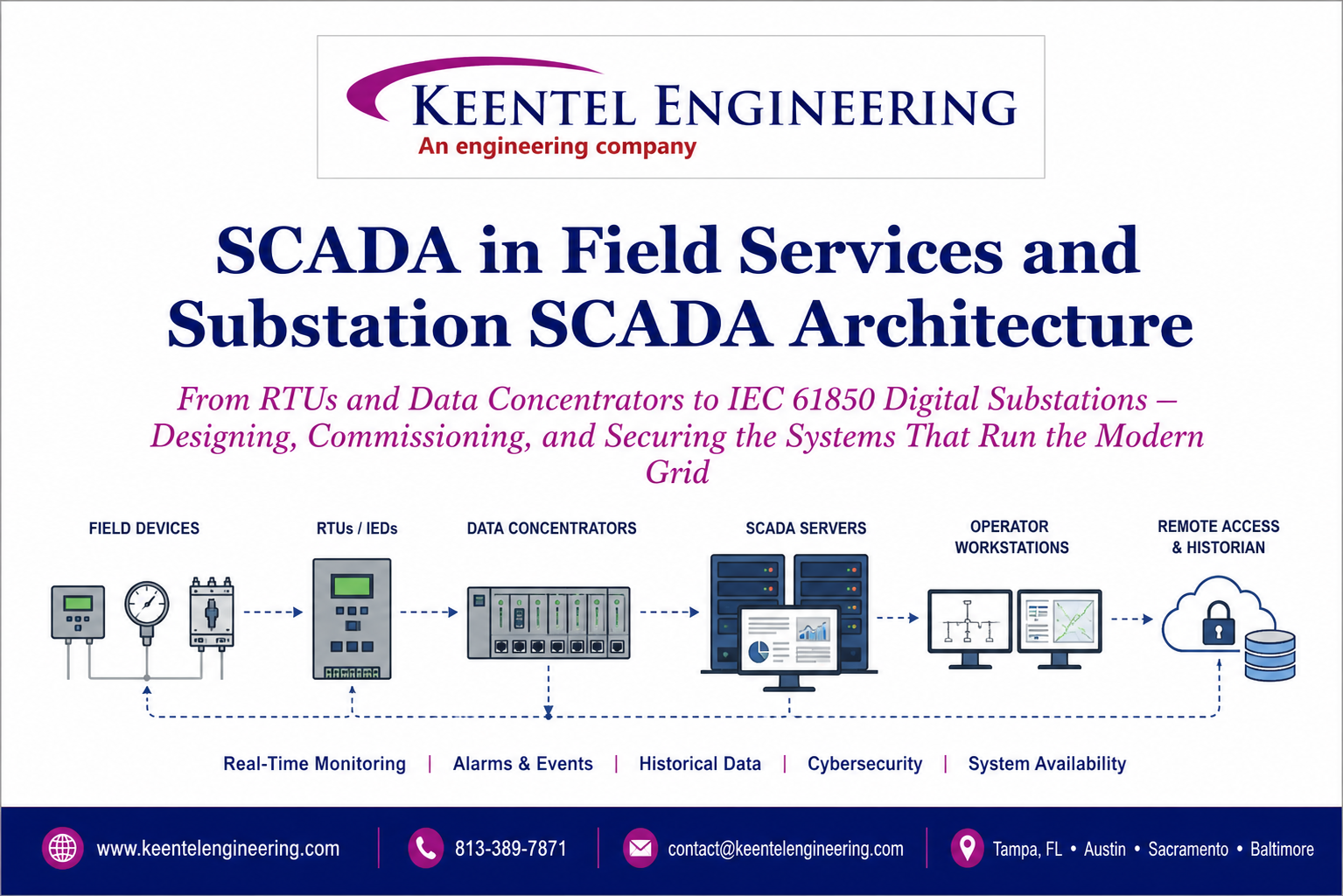
Learn SCADA architecture, IEC 61850, RTUs, IEDs, DNP3, digital substations, commissioning, cybersecurity, and field services for modern power systems.