
A Coordinated Electric System Interconnection Review—the utility’s deep-dive on technical and cost impacts of your project.
Challenge: Frequent false tripping using conventional electromechanical relays
Solution: SEL-487E integration with multi-terminal differential protection and dynamic inrush restraint
Result: 90% reduction in false trips, saving over $250,000 in downtime
ERCOT enforces all of the above through simulation, which means your model is your compliance case. The bar is now high:
- Whole-facility scope. The model must represent everything the IT load, the UPS and power conversion, the cooling plant, the protection and control systems in formats compatible with ERCOT's study platforms (PSS/E, PSCAD, TSAT).
- Real control loops, not approximations. Generic textbook representations are unacceptable. The model must capture the actual inner control behavior of your power electronics.
- Hardware-validated converter models. For electronic loads, the PSCAD model must be benchmarked against actual hardware testing including voltage ride-through and subsynchronous response. A model assembled from standard PSCAD library blocks fails by definition, because a generic block has never been tested against your vendor's hardware. The good news: validation is a hardware-type test, so results for a given converter product are reusable across every facility that uses it.
- Format migration. Facilities that previously submitted the older composite load model (CMLD) format must transition to EPRI's PERC1 format.
- Three checkpoints. Models are reviewed before the stability study begins (no model, no study), before each quarterly stability assessment, and for electronic loads one final time before energization, when you must submit as-built models with a documented comparison against the previously studied data and a sworn attestation that the model matches actual field settings. ERCOT's review takes 10 business days, extendable by 20 put it on your critical path.
- A living obligation. Change your technology, controls, or relay settings in a way that affects ride-through including converting a crypto mining site to an AI data center — and you've triggered a new interconnection study, even if your megawatts don't change.
| Parameter | Detail |
|---|---|
| System | 230 kV / 138 kV transmission corridors, wind and wet-snow icing exposure |
| Data basis | 15 years of minute-resolution forced-outage records + regional weather observations |
| Core methods | Event grouping, MVA performance curves, time-to-95%-restore, area outage rate curves, fragility modeling, rerun-history benefits, exceedance and log-domain risk metrics |
| Headline result | ≈85% of maximum resilience benefit at 60% of original capital; worst-event restoration window cut from 11 days to 5 in rerun-history terms |
| Decision supported | Capital portfolio selection; resilience plan filing; post-investment verification framework |
| System / Topic | Governing Standard(s) | What It Controls |
|---|---|---|
| Overall plant electrical distribution | IEEE 141 (Red Book); IEEE 666 | Distribution architecture, voltage selection, design of generating station auxiliary service systems |
| Power system studies | IEEE 399 (Brown Book); IEEE 551 | Load flow, symmetrical/asymmetrical short circuit, motor starting methodologies down to the lowest LV panelboard |
| Protection & coordination | IEEE 242 (Buff Book); IEEE 3004.5; IEEE C37 series | Generator relaying (21, 59N, 87G), time-current coordination, selective clearing between LV and MV tiers |
| GSU / UAT / SST transformers | IEEE C57.12.00 and C57 family | Transformer ratings, impedance, testing, loading |
| HV switchyard breakers | IEEE C37.06 | AC high-voltage circuit breaker preferred ratings |
| MV switchgear (13.8 kV) | IEEE C37.20.2; IEEE C37.20.7 | Metal-clad construction, compartmentalization, vacuum breakers; arc-resistant design with plenum venting |
| MV cable | UL 1072; ICEA S-93-639 (NEMA WC 74) | Type MV-105 shielded cable, 133% insulation level for HRG systems |
| LV switchgear (480 V) | IEEE C37.13; UL 1558 | Metal-enclosed LV power circuit breaker switchgear to 635 V, draw-out ACBs with electronic trip units |
| Motor control centers | UL 845; NEMA ICS 18 | LV-MCC construction, MCCB/MCP protection for motors under ~200 HP |
| Motors | NEMA MG-1 | Motor performance, starting characteristics, service factors |
| DC & battery systems | IEEE 485; IEEE 946 | Lead-acid battery sizing (125/250 VDC), DC auxiliary system design |
| Grounding | IEEE 80; IEEE 142 (Green Book) | Ground grid step/touch potential limits; system grounding including high-resistance grounding |
| Lightning protection | IEEE 998 | Direct-stroke shielding of switchyard and outdoor generator structures |
| Arc flash & electrical safety | IEEE 1584; NFPA 70E | Incident energy calculation; worker safety boundaries and PPE |
| Fire protection | NFPA 850 | Fire protection and risk management for combustion turbine generating plants |
| Installation code | NEC (NFPA 70); NESC | Wiring methods inside the plant fence; overhead/outdoor clearances at the switchyard |
| Interconnection & compliance | FERC LGIP; NERC MOD-025/026/027, PRC-019/024/029, FAC-008 | Interconnection process, model validation, protection/ride-through coordination, facility ratings |
| IFC / Construction Deliverable | Purpose |
|---|---|
| Stamped IFC packages | Legal basis for construction; P.E. responsible charge |
| Final relay settings & TCCs | Protection as-installed matches the coordination study |
| Calculation archive | Owner records; NERC audit evidence trail |
| Commissioning procedures | Safe, sequenced energization; MOD field testing |
| Construction support | RFIs, field changes, FAT/SAT witness |
| As-builts & model handoff | Operating baseline; future study currency |
| Metric | Outcome |
|---|---|
| Defects found pre-occupancy | Three topology defects and one settings-mismatch family corrected before load migration; the shared-switchboard defect alone would have invalidated the concurrently-maintainable claim on day one |
| IST findings | Fourteen additional discrepancies surfaced under scenario testing (control logic, alarm mapping, one generator sequencing fault) — all closed before handover instead of during operations |
| Black-building test | Passed on second execution; the first attempt exposed the generator sequencing fault under true block load, exactly the failure the compressed plan would never have found |
| Handover quality | Operations team certified on the actual failure scenarios; corrected EOPs and settings documentation delivered as controlled documents |
| Business outcome | Occupancy proceeded three weeks behind the original date — against an independent estimate that the uncorrected sequencing fault carried a high probability of a full facility outage within the first year |
Part 2 — Frequently Asked Questions: Large Load Interconnection
An electric grid must remain in continuous balance — generation onto the grid must equal consumption from it at every instant. PJM achieves this balance, and prices it, through a layered market architecture. Each layer operates on a different time horizon, and each one touches project economics differently.
Inside a Battery Energy Storage System
Jul 18, 2026 | Blog
1. Introduction: The Grid Was Never Built for This
The power grid was engineered around a simple premise: large, dispatchable, synchronous generators producing steady, predictable power, scheduled by a central operator. Renewable energy breaks every clause of that premise. Solar output collapses at sunset and swings with every passing cloud; wind rises and falls with the weather; both connect through power electronics rather than rotating machines. Yet national policy worldwide is pushing renewable penetration relentlessly higher — with individual country targets measured in the hundreds of gigawatts by 2030 — and there is no going back to a fossil-dominated fleet.
So the defining question of the modern grid is blunt: how do you keep the lights on when the sun sets and the wind stops? A single containerized battery unit of the kind now rolling off production lines can power on the order of a hundred homes simultaneously — and, more importantly, can help stabilize the entire grid around it. That technology is the Battery Energy Storage System, or BESS. It is often dismissed as 'a giant battery box.' It is not. A grid-scale BESS is a highly engineered system of systems — electrochemical, power-electronic, thermal, protective, and digital — and every one of those subsystems has to be designed, integrated, studied, and commissioned correctly for the asset to be safe, bankable, and grid-compliant. This article walks through why BESS exists, what it does for the grid, and — component by component — what is actually inside the box.
2. Four Problems Renewables Create for the Grid
2.1 Fluctuating, Uncontrollable Output
Renewable output is dictated by nature, not by dispatch instructions. A solar plant produces only while the sun shines; output falls to zero at dusk and fluctuates continuously under cloud cover during the day. Wind output varies with wind speed on timescales from seconds to seasons. The legacy grid was designed for steady, schedulable generation, and it has no inherent mechanism for absorbing rapid, frequent, weather-driven power swings while holding frequency and voltage within limits.
2.2 Declining System Inertia
Conventional plants use large synchronous generators whose heavy rotating masses store kinetic energy — inertia. The intuition is a bicycle wheel: once spinning, it keeps rotating even after you stop pedaling. When a generator trips or load steps suddenly, that stored rotational energy resists the frequency change instantly, slowing the rate of change of frequency (RoCoF) and buying time for slower controls to respond. Inverter-based renewables have no rotating parts; every synchronous megawatt they displace removes inertia from the system. As penetration rises, frequency control becomes harder and the risk of fast, deep frequency excursions grows. (For a full treatment of how grid-forming inverters restore synthetic inertia, see our companion publication on grid-forming technology.)
2.3 Loss of Visibility and Controllability
Operators once enjoyed near-total visibility and centralized control: thermal, hydro, and nuclear output could be scheduled and adjusted on command. Renewable generation is inherently uncertain — accurate forecasting of solar and wind, short-term and long-term, remains difficult — and renewable plants are geographically dispersed, frequently connected at weak points in the network. Centralized dispatch gives way to a coordination problem of far higher dimensionality.
2.4 Erosion of Reactive Power Control
Reactive power is sometimes dismissed as 'useless power.' In reality it is the currency of voltage control: shunt reactors, capacitor banks, and generator excitation systems all regulate voltage by managing reactive power. As conventional plants retire and simple grid-following solar inverters proliferate — many historically operated at unity power factor with no reactive contribution — the system's reactive resources thin out precisely as its need for dynamic voltage support grows.
KEENTEL INSIGHT
These Are Interconnection Problems, Not Abstractions
Every one of these four problems shows up concretely in interconnection studies: ramp-rate and curtailment provisions, RoCoF and frequency ride-through requirements, forecasting and telemetry obligations, and reactive capability ranges specified at the point of interconnection. A BESS that is engineered against the grid code from day one clears these hurdles; one specified as a commodity 'battery box' does not.
3. Why Batteries Won the Storage Race
Battery storage is not the only storage technology, and it did not win by default. Pumped hydro stores enormous energy but demands specific geography and offers limited flexibility for fast grid services. Flywheels respond in milliseconds but store energy for only short durations. Thermal storage is application-specific. Hydrogen holds long-duration promise but still faces round-trip efficiency and cost hurdles. Each serves a purpose; none serves every purpose.
| Technology | Strength | Limitation |
|---|---|---|
| Pumped hydro | Very large energy capacity; proven at scale | Geography-dependent; slow to site and permit; limited fast-service flexibility |
| Flywheel | Millisecond response; high cycle life | Seconds-to-minutes duration only |
| Hydrogen | Long-duration and seasonal potential | Low round-trip efficiency; developing cost base |
| Battery (BESS) | Fast response, siting flexibility, modular scaling, multi-service capability | Duration economics; degradation management; fire safety engineering |
BESS is the one technology that can plausibly address the full stack of grid needs: it responds in milliseconds, sites almost anywhere, scales modularly — need more capacity, add another enclosure — and serves many applications from one asset: energy shifting and arbitrage, peak shaving, frequency regulation and fast frequency response, renewable output smoothing, reactive power and voltage support, transmission and distribution deferral, resource adequacy capacity, and even black start. Think of it as a power bank for the entire grid — but one that also talks back to the grid in real time.
4. Inside the Box: The Anatomy of a BESS
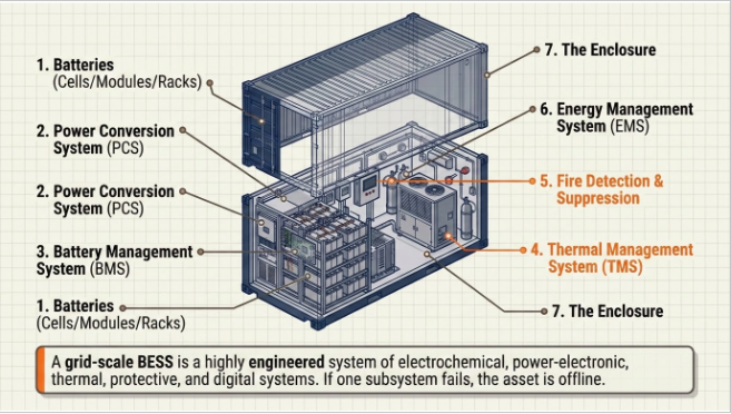
A representative modern outdoor cabinet packs on the order of 250 kWh into a single weatherproof enclosure; utility-scale sites parallel hundreds of such units or larger containers into plants of hundreds of megawatt-hours. Whatever the scale, the same subsystems appear, and each deserves engineering attention.
4.1 The Battery: Cells, Modules, and Racks
There is no single giant battery inside. The energy store is built hierarchically: individual electrochemical cells are assembled into modules; modules are connected — typically in series — into racks or packs; racks are paralleled to form the DC block. The hierarchy is deliberate. Modularity localizes both failure and maintenance: a faulty module can be isolated, extracted, and replaced without disturbing the rest of the system.
Today's grid-scale market is dominated by lithium-ion chemistry, and within lithium-ion, lithium iron phosphate (LFP) has become the workhorse for stationary storage. The reasons are practical: competitive cost per kilowatt-hour, high energy density in a compact footprint, long cycle life, and — critically for stationary applications — better thermal stability and a higher thermal-runaway onset threshold than nickel-rich chemistries. Chemistry selection still matters at the project level: cycle-life warranties, calendar aging, temperature sensitivity, and end-of-life augmentation strategy all trace back to the cell.
4.2 Power Conversion System (PCS): The Translator
Batteries speak DC; the grid speaks AC. The Power Conversion System is the bidirectional translator between the two. Charging, it operates as a rectifier — converting grid AC to DC at the battery bus voltage. Discharging, it operates as an inverter — converting the battery's DC back to grid-compatible AC. In a representative cabinet-scale system, the PCS converts a low-voltage AC connection (on the order of 400 V) to a DC bus in the 800+ V range and back again; utility-scale PCS units operate at higher powers with medium-voltage step-up transformers immediately downstream.
PCS packaging follows two patterns: integrated within the same cabinet as the batteries, or housed in dedicated PCS cabinets or containers — the norm on large projects. Either way, the PCS is a single point of consequence: if it fails, the unit can neither charge nor discharge, and the asset is offline. PCS selection also determines far more than power rating — grid-support capability (reactive power range, ride-through behavior, and increasingly grid-forming capability), harmonic performance, efficiency curves, and overload headroom are all set here. On the modern grid, the PCS is where a battery stops being a load/source and becomes a grid asset.
4.3 Battery Management System (BMS): The Watchdog
Hundreds of cells sharing current raises an obvious question: who ensures no individual cell is over-stressed — over-temperature, over-voltage, over-current — while the fleet charges and discharges? Unmanaged, cell-level abuse is the road to thermal runaway. The Battery Management System is the embedded watchdog that prevents it. 'Embedded' is the operative word: unlike a general-purpose computer, a BMS is purpose-built firmware doing one job — the way a washing machine controller runs wash cycles and nothing else. Its four core functions:
- Monitoring. Continuous measurement of cell and module temperatures, voltages, and currents, published to every other stakeholder in the control chain.
- Protection. On detecting an out-of-limit condition, the BMS commands the distribution/disconnection hardware to isolate the affected module before a local fault escalates.
- Performance optimization. The BMS maintains state-of-charge (SOC) and state-of-health estimates and performs cell balancing, so the energy management layer can make accurate charge/discharge decisions and the plant delivers its rated capacity over life.
- Communication.
The BMS is in constant dialogue with the PCS and the plant EMS; every protective action and every dispatch decision depends on the data it streams.
KEENTEL INSIGHT
SOC Accuracy Is a Revenue Issue
SOC estimation quality is commonly treated as a battery-health topic. It is equally a market topic: available-energy misreporting flows straight into dispatch errors, availability penalties, and settlement disputes. Duty cycles with sustained low-magnitude currents — frequency response and inertial services in particular — sit exactly where current sensing is least accurate, so BMS measurement architecture should be evaluated against the intended service stack, not just against nameplate cycling.
4.4 Thermal Management System (TMS): Keeping Chemistry Comfortable
Even the smartest electronics cannot help a battery that is running hot. A useful rule of thumb: if the temperature is uncomfortable for a human, it is probably uncomfortable for a lithium-ion cell. Performance is best in roughly the 20–40 °C band. Run colder and performance and available capacity drop; run hotter and electrolyte heating accelerates degradation and, at the extreme, initiates thermal runaway. Packing hundreds of kilowatt-hours into a compact enclosure guarantees heat, so heat must be actively removed.
Two architectures dominate. HVAC (forced-air) systems suit lower energy densities and some site conditions; liquid cooling — coolant pumped through module-level cold plates from pumps at the base of the enclosure — has become the default for compact, high-density products because it removes heat where it is generated and holds tighter cell-to-cell temperature uniformity. Uniformity matters as much as absolute temperature: thermal gradients across a rack drive uneven aging, which erodes usable capacity years before warranty end.
4.5 Fire Detection and Suppression: Engineering for the Bad Day
A BESS concentrates an enormous amount of stored energy, and the honest engineering position is that a fully developed lithium-ion battery fire is extraordinarily difficult to extinguish. The design objective is therefore early detection and escalation prevention, not heroic firefighting. A modern enclosure carries a layered sensor suite — smoke, off-gas, temperature, and humidity detection — monitoring conditions continuously and feeding the suppression controller. Off-gas detection deserves emphasis: cells vent characteristic gases before thermal runaway fully develops, so gas sensing provides the earliest actionable warning in the sequence.
Suppression architecture scales with the enclosure. At module level, aerosol-based suppression is common in cabinet-class products: a heat-activated tube ruptures and floods the affected module, containing the event within that module. Larger 20-foot containers employ different schemes — clean-agent flooding, water-based systems, dedicated deflagration venting — selected against the specific enclosure volume and energy. In all cases, suppression is one layer of a defense-in-depth stack that includes cell chemistry selection, BMS protective action, thermal management, enclosure-level gas management, spacing and separation, and emergency response planning — the framework codified in NFPA 855 and validated through UL 9540A large-scale fire testing.
4.6 Energy Management System (EMS): The Brain
With storage, conversion, and safety in place, one question remains: when should the plant charge, and when should it discharge? Get it backwards — charging at peak prices and discharging into the trough — and an arbitrage asset loses money on every cycle. The Energy Management System is the software layer that makes those decisions automatically. It sits in constant communication with the BMS (state of charge, available capacity, health) and commands the PCS (charge, discharge, setpoints), executing whatever application logic the owner programs: arbitrage, peak shaving, frequency response stacking, renewable smoothing, or coordinated multi-service dispatch.
It is fair to say the EMS decides whether a BESS is a good investment or merely a functioning one: two identical hardware plants with different EMS strategies produce very different revenue. On utility-scale sites the EMS also integrates upward — into plant SCADA, operator telemetry, and market bidding systems — which makes cybersecurity, protocol compliance, and dispatch-latency performance genuine engineering requirements rather than IT afterthoughts.
4.7 The Enclosure: More Than a Metal Box
Everything above lives inside an enclosure engineered for decades outdoors. Cabinet-class products carry ingress protection ratings on the order of IP55 — sealed against dust and water jets, suitable for harsh environments — with corrosion-rated construction for coastal and industrial atmospheres. The enclosure is also where modular scaling happens: additional capacity means placing and paralleling another cabinet, not redesigning the plant. At utility scale, the same role is played by purpose-built containers with integrated thermal, fire, and access systems.
4.8 Beyond the Box: Balance of Plant
The container is where the product ends and the project begins. A grid-connected BESS still requires: medium-voltage step-up transformers and switchgear; AC collection design; protective relaying coordinated across the PCS, feeders, and point of interconnection; grounding and lightning protection; auxiliary power for cooling and controls (a real and often underestimated load); SCADA and metering; and civil works. Interconnection itself brings power system studies — load flow, short circuit, protection coordination, harmonics, and increasingly EMT-level dynamic studies as grid codes tighten for inverter-based resources. This balance-of-plant and studies scope is where projects most often stall — and where disciplined engineering pays for itself.
5. Sizing, Augmentation, and Life-Cycle Design
Correct sizing is a system exercise, not a datasheet lookup. Power (MW) and energy (MWh) ratings must be derived from the application stack — a frequency-response asset and a four-hour capacity asset are different machines. Usable energy differs from nameplate: depth-of-discharge windows, temperature derating, auxiliary consumption, and conversion losses all subtract. And batteries degrade: a plant sized exactly to its day-one requirement fails its requirement in year three. Life-cycle design therefore builds in either initial oversizing or a planned augmentation program — physical space, DC architecture, and interconnection headroom reserved for adding modules as capacity fades. The modular cabinet architecture makes augmentation practical, but only if the plant was engineered for it from the start.
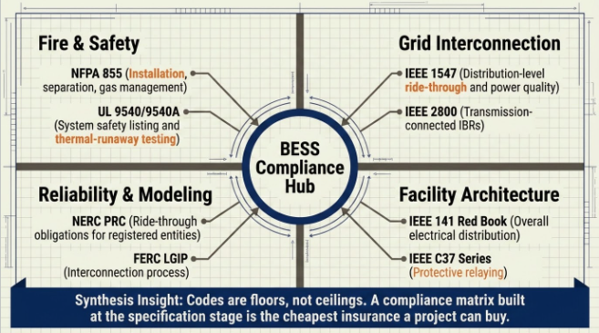
6. Standards and Codes Every BESS Project Must Satisfy
| Domain | Key Standards / Codes | What They Govern |
|---|---|---|
| Fire safety | NFPA 855; UL 9540 / UL 9540A | Installation requirements, separation, gas management; system safety listing and thermal-runaway fire testing |
| Grid interconnection | IEEE 1547 (distribution); IEEE 2800 (transmission IBRs) | Ride-through, reactive capability, power quality, and performance at the point of interconnection |
| Power quality | IEEE 519 | Harmonic distortion limits at the PCC |
| Protection & grounding | IEEE 80 / 81 / 142; C37 series | Grounding system design and testing; protective relaying |
| Reliability compliance | NERC standards (incl. PRC ride-through requirements) | Registered-entity obligations for grid-connected storage |
Codes are floors, not ceilings. Utility-specific interconnection requirements, insurer expectations, and local AHJ interpretations routinely exceed the published minimums — and they change. A compliance matrix assembled at the specification stage, and maintained through commissioning, is the cheapest insurance a BESS project can buy.
7. How Keentel Engineering Supports BESS Projects
Keentel Engineering LLC provides independent, vendor-neutral engineering across the full BESS life cycle:
- Concept & Sizing. Feasibility, application-stack definition, MW/MWh sizing, usable-energy and degradation modeling, and augmentation planning.
- Grid Interconnection & Studies. Interconnection applications and studies — load flow, short circuit, protection coordination, harmonics, and EMT dynamic modeling for IBR grid-code compliance.
- Technology Procurement Support. Specification and bid evaluation of batteries, PCS, BMS, TMS, fire protection, and EMS; factory and site test witnessing; vendor claim verification.
- Balance-of-Plant Design. Substation and MV collection design, protective relaying, grounding (IEEE 80/81), auxiliary systems, and SCADA integration.
- Safety & Code Compliance. NFPA 855 / UL 9540A compliance review, hazard mitigation analysis, and coordination with AHJs and insurers.
- Owner's Engineer & Compliance.
Owner's engineer services from contract through commissioning, plus NERC compliance program development for operating assets.
Case Studies
The following case studies are drawn from representative engagements. All client, project, personnel,
and location identifiers have been removed or generalized to protect confidentiality.
Case Study 1: Utility-Scale Standalone BESS — Interconnection and
Grid-Code Compliance
Challenge
A developer advancing a 100 MW / 400 MWh standalone BESS faced a transmission
interconnection process with tightening inverter-based resource requirements, including EMT model
submission and demonstrated ride-through compliance. The originally proposed equipment package
had been selected on price, and its PCS dynamic models were incomplete against the interconnecting
utility's requirements — putting the queue position at risk of restudy delays.
Approach
Keentel built a requirement-by-requirement compliance matrix from the applicable grid code
and utility technical standards, then benchmarked the vendor's EMT models against it. Gaps were
documented and driven back to the supplier for model correction and, where hardware capability was
the constraint, reflected in a revised PCS specification. Keentel executed the supporting study suite —
load flow, short circuit, protection coordination, harmonic screening against IEEE 519, and EMT dynamic
verification of ride-through and reactive capability at the point of interconnection — and prepared
submission-ready documentation.
Outcome
The project cleared its interconnection study cycle without a restudy loop, the equipment
specification was corrected before purchase orders were placed, and the developer retained its queue
position and financing timeline. The compliance matrix remained in service through commissioning as
the master verification document.
Case Study 2: Industrial Peak Shaving BESS — Sizing, Protection, and
Savings Verification
Challenge
A large industrial facility with sharp demand peaks sought a behind-the-meter BESS to reduce
demand charges. Vendor proposals ranged widely in power and energy ratings, and the facility's aging
medium-voltage distribution raised protection coordination and power quality questions that no bidder
had addressed.
Approach
Keentel analyzed a full year of interval load data to characterize peak frequency, magnitude,
and duration, then sized the system against the facility's actual tariff structure — accounting for usable-
energy deratings, auxiliary consumption, round-trip efficiency, and end-of-warranty degradation rather
than nameplate figures. The engagement included protection coordination across the new PCS and
existing switchgear, harmonic assessment of the converter against facility power quality limits, thermal
and fire-code review of the proposed indoor-adjacent siting per NFPA 855, and a revised siting
recommendation to an outdoor pad with code-compliant separation.
Outcome
The right-sized system came in materially smaller than the leading vendor proposal while
capturing effectively the same demand-charge savings, the protection scheme was coordinated before
Inside a Battery Energy Storage System — All Components Explained
keentelengineering.com | © 2026 Keentel Engineering LLC Page 15 of 1
installation rather than patched after, and first-year measured savings tracked the engineering model
within a few percent — supporting the facility's internal capital case for a second phase.
Case Study 3: Operating BESS Fleet — Safety Compliance and
Augmentation Roadmap
Challenge
An asset owner operating multiple cabinet-based BESS installations commissioned in earlier
code cycles needed a portfolio review: authorities and insurers were signaling alignment with current
NFPA 855 expectations, and measured capacity fade across the fleet was outpacing the original revenue
model.
Approach
Keentel performed site-by-site gap assessments against current fire-safety expectations —
detection coverage (including off-gas sensing), suppression architecture, separation distances, gas
management, signage, and emergency response documentation — and prioritized findings by risk and
cost. In parallel, Keentel analyzed BMS-recorded operating data to model degradation trajectories per
site, then developed an augmentation roadmap: which sites could accept additional cabinets within
existing electrical and spatial headroom, which required interconnection amendments, and the optimal
sequencing of augmentation capital against contracted revenue obligations.
Outcome
The owner received a defensible, prioritized compliance program accepted by its insurer,
avoided a blanket retrofit by targeting only the genuinely deficient sites, and adopted a staged
augmentation plan that restored contracted capacity at the lowest net present cost — converting a
looming portfolio problem into a scheduled maintenance program.
Frequently Asked Questions
Q1. What exactly is a BESS?
A Battery Energy Storage System is an integrated, grid-connected system — not just a battery —
comprising electrochemical storage (cells, modules, racks), a bidirectional power conversion system
(PCS), a battery management system (BMS), thermal management, fire detection and suppression, an
energy management system (EMS), and a weatherproof enclosure, all supported by balance-of-plant
equipment. It stores surplus electrical energy and dispatches it back to the grid on command, while also
providing real-time grid services.
Q2. Why does the grid suddenly need storage?
Because renewables broke four assumptions the grid was built on: output is now fluctuating and
weather-driven rather than schedulable; system inertia falls as synchronous machines are displaced by
inverters; operator visibility and centralized control diminish as generation disperses; and reactive
power resources for voltage control thin out. Storage is the one technology that addresses all four while
remaining fast, siteable, and modular.
Q3. What is inertia, in plain terms?
The kinetic energy stored in the heavy rotating shafts of conventional generators — like a bicycle wheel
that keeps spinning after you stop pedaling. When a disturbance hits, that stored energy resists the
frequency change instantly, slowing the rate of change of frequency and buying time for controls to act.
Inverter-based renewables carry none, which is why declining inertia is a defining challenge of high-
renewables grids — and why grid-forming BESS, which emulates inertia in software, is increasingly
required by grid codes.
Q4. Why did lithium-ion — and LFP specifically — come to dominate grid storage?
Cost-effectiveness and packaging: high energy in a small footprint at a competitive price, with strong
cycle life. Within lithium-ion, LFP won the stationary market on thermal stability — a higher thermal-
runaway onset threshold and more forgiving abuse tolerance than nickel-rich chemistries — traded
against somewhat lower energy density, which matters less when the asset sits on the ground rather
than in a vehicle.
Q5. What does the PCS do, and why is it so critical?
The PCS is the bidirectional AC/DC translator: rectifier when charging, inverter when discharging. It is a
single point of consequence — if the PCS fails, the plant can neither charge nor discharge. It also defines
the plant's grid personality: reactive capability, ride-through behavior, harmonic performance, overload
headroom, and grid-forming capability all live in the PCS.
Q6. What are the four functions of a BMS?
Monitoring (continuous cell/module temperature, voltage, and current measurement), protection
(isolating a module when limits are violated, before escalation), performance optimization (SOC/state-
of-health estimation and cell balancing so dispatch decisions are accurate), and communication
(constant data exchange with the PCS and EMS). It is an embedded, single-purpose system — the
watchdog of the battery.
Q7. What temperature range do lithium-ion batteries want, and what happens outside it?
Roughly 20–40 °C for best performance. Colder, and available capacity and performance drop. Hotter,
and degradation accelerates; at the extreme, electrolyte heating can initiate thermal runaway — a self-
sustaining exothermic failure. That is why active thermal management is mandatory, not optional.
Q8. Liquid cooling or HVAC — which is better?
It depends on energy density and application. Forced-air HVAC remains viable for lower-density layouts.
Liquid cooling — pumped coolant through module-level cold plates — has become the default for
compact, high-density cabinets because it removes heat at the source and holds tighter cell-to-cell
temperature uniformity, which slows uneven aging. Uniformity is as important as the absolute setpoint.
Q9. How is fire risk actually managed in a BESS?
Through defense in depth, because a developed lithium-ion fire is extremely difficult to extinguish.
Layers include: stable chemistry selection (LFP), BMS protective isolation, thermal management, early
detection (smoke, temperature, humidity, and especially off-gas sensors, which detect venting before
runaway fully develops), suppression scaled to the enclosure (module-level aerosol in cabinets; clean-
agent, water-based, or deflagration-vented schemes in large containers), physical separation, and
emergency response planning — the framework of NFPA 855, validated by UL 9540A testing.
Q10. What does the EMS actually decide?
When to charge, when to discharge, and in service of which application — arbitrage, peak shaving,
frequency response, smoothing, or a stacked combination. It reads state of charge from the BMS and
commands the PCS accordingly. Two identical hardware plants with different EMS strategies deliver very
different revenue; the EMS is, in a real sense, the profitability layer of the asset.
Q11. How does modular scaling work?
Capacity grows by paralleling additional cabinets or containers rather than redesigning the plant — one
more enclosure, double the energy at that node. The same modularity applies inside: a failed module is
isolated and swapped without disturbing the rack. But scaling headroom must be engineered up front:
space, DC architecture, transformer and interconnection capacity all have to anticipate it.
Q12. What is augmentation and why plan for it at day one?
Batteries fade; a plant sized exactly to its requirement at commissioning falls short within a few years.
Augmentation is the planned addition of modules or cabinets over the asset's life to restore capacity.
Doing it economically requires reserved space, compatible DC architecture, and interconnection
headroom — decisions that can only be made cheaply at the design stage.
Q13. What studies does a BESS interconnection require?
Typically load flow, short circuit, and protection coordination as a baseline; harmonic analysis against
IEEE 519; and, increasingly, EMT-level dynamic studies as grid codes for inverter-based resources tighten
(IEEE 2800 at transmission, IEEE 1547 at distribution). Grid-forming requirements add validation layers
— benchmarked EMT models, hardware-in-the-loop testing, and staged site tests.
Q14. Is a BESS just for storing solar energy overnight?
No. Energy shifting is one application among many: peak shaving, arbitrage, frequency regulation and
fast frequency response, renewable output smoothing, reactive power and voltage support,
transmission and distribution investment deferral, resource adequacy capacity, and black start. The
most valuable plants stack several services on one asset — which is precisely why EMS strategy and PCS
capability matter so much.
Q15. What most often goes wrong on BESS projects?
Rarely the battery itself. The recurring failure points are system-level: sizing that ignored degradation
and auxiliary loads; PCS capability mismatched to grid-code requirements; SOC accuracy problems under
real service duty; thermal non-uniformity driving early capacity fade; fire-code and AHJ requirements
addressed too late; and interconnection studies started after equipment was purchased. All are
preventable with independent engineering early in the project.
Disclaimer
This publication is provided by Keentel Engineering LLC for general informational purposes only and does not constitute engineering, legal, financial, or investment advice for any specific project. Descriptions of equipment, ratings, and performance characteristics are illustrative and vary by product and application. Case studies are representative and anonymized; identifying details have been removed or generalized. Keentel Engineering LLC is not affiliated with, endorsed by, or acting on behalf of any equipment manufacturer, system operator, standards organization, or other entity referenced directly or indirectly herein.
Readers should obtain project-specific engineering analysis before making design, procurement, or investment decisions. ©
2026 Keentel Engineering LLC. All rights reserved.

About the Author:
Sandip "Sonny" R. Patel, P.E.
IEEE Senior Member · Founder & CEO, Keentel Engineering
In 1995, Sonny Patel earned his Electrical Engineering degree from the University of Illinois. But degrees don't build legacies — action does.
For three decades, he has worked the power industry from every side of the table: 16 years as a utility engineer at Exelon/Commonwealth Edison; generation leadership across hydroelectric, industrial steam turbine, and a 9 GW renewable fleet; NERC Regional Entity Senior Compliance Engineer and Audit Team Lead, auditing some of the nation's largest utilities; and testing and commissioning lead on equipment up to 765 kV — the very top of the North American grid.Utility. Generator. Regulator. Consultant. Few engineers have seen all four seats. Fewer still have sat in them.
His experience spans nuclear, hydro, conventional generation, renewables, oil and gas, mining — and today's data centers, where he is authoring a three-book series on data center design. He is a Licensed Professional Engineer in six states and a Licensed Electrical Contractor in Florida (Unlimited EC) — he doesn't just design the work; he's qualified to stand behind its execution.Today, as Founder and CEO of Keentel Engineering, Sonny leads a nationwide team of engineers delivering substation design, power system studies, NERC compliance, and commissioning — done right, coast to coast.Three decades. Every side of the table. One standard: accountable engineering.
Services

Let's Discuss Your Project
Let's book a call to discuss your electrical engineering project that we can help you with.
About the Author:
Sandip "Sonny" R. Patel, P.E.
IEEE Senior Member · Founder & CEO, Keentel Engineering
In 1995, Sonny Patel earned his Electrical Engineering degree from the University of Illinois. But degrees don't build legacies — action does.
For three decades, he has worked the power industry from every side of the table: 16 years as a utility engineer at Exelon/Commonwealth Edison; generation leadership across hydroelectric, industrial steam turbine, and a 9 GW renewable fleet; NERC Regional Entity Senior Compliance Engineer and Audit Team Lead, auditing some of the nation's largest utilities; and testing and commissioning lead on equipment up to 765 kV — the very top of the North American grid.
Utility. Generator. Regulator. Consultant. Few engineers have seen all four seats. Fewer still have sat in them.
His experience spans nuclear, hydro, conventional generation, renewables, oil and gas, mining — and today's data centers, where he is authoring a three-book series on data center design. He is a Licensed Professional Engineer in six states and a Licensed Electrical Contractor in Florida (Unlimited EC) — he doesn't just design the work; he's qualified to stand behind its execution.
Today, as Founder and CEO of Keentel Engineering, Sonny leads a nationwide team of engineers delivering substation design, power system studies, NERC compliance, and commissioning — done right, coast to coast.Three decades. Every side of the table. One standard: accountable engineering.
Leave a Comment
Thank you for contacting us.
We will get back to you as soon as possible.
We will get back to you as soon as possible.
Oops, there was an error sending your message.
Please try again later.
Please try again later.
Related Posts

By SANDIP R PATEL
•
October 3, 2026
Engineering guide to PRC-028 disturbance recording, PRC-029 ride-through and PRC-030 event detection for inverter-based resources.

By SANDIP R PATEL
•
October 3, 2026
A practical guide to SSO classification, SSR, PEDI, Wind-SSCI, EMT analysis, mitigation and protection based on CIGRE TB 909.

By SANDIP R PATEL
•
October 3, 2026
Learn ERCOT generator testing for PFR, MOD-025 and MOD-026/027, including staged tests, capability verification, dynamic models and field testing.

By SANDIP R PATEL
•
October 3, 2026
Learn how PV string I-V curve testing identifies hidden solar performance losses, including soiling, shading, mismatch, degradation, and wiring faults.

By SANDIP R PATEL
•
October 3, 2026
Learn how active harmonic filters work, how to size AHF systems, reduce VFD harmonics, calculate losses, and meet IEEE 519 TDD limits at the PCC.
By SANDIP R PATEL
•
October 3, 2026
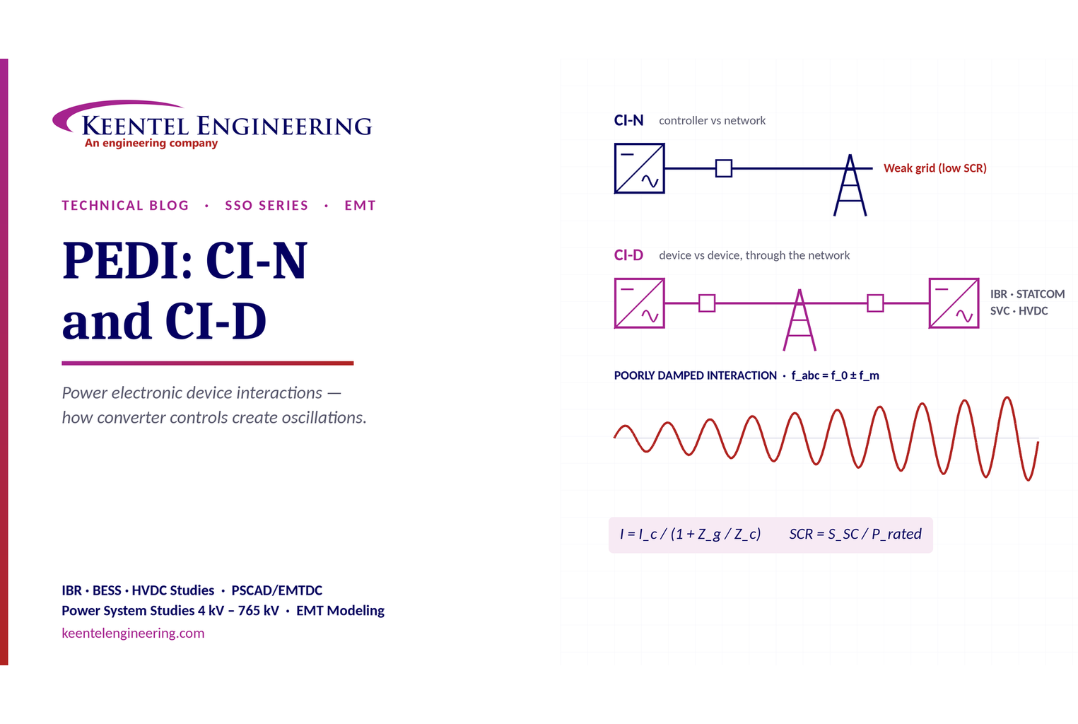
Learn power electronic device interactions (PEDI), including CI-N and CI-D, weak-grid stability, SCR, EMT studies, impedance analysis and mitigation for IBRs.
By SANDIP R PATEL
•
October 3, 2026
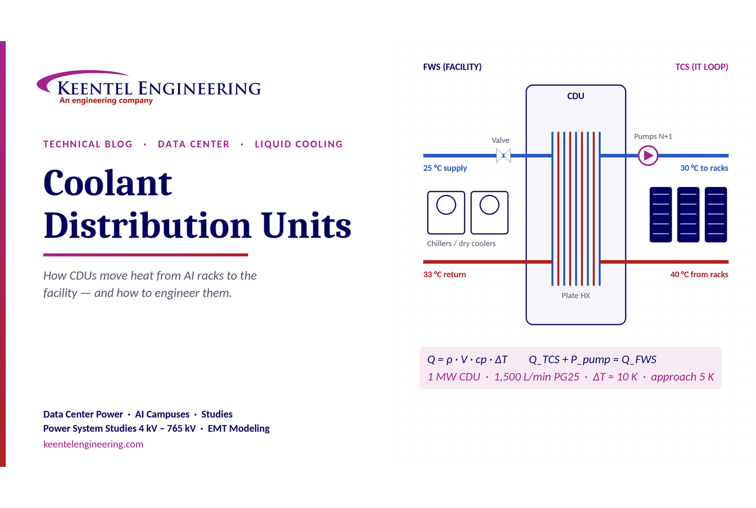
Learn how data center coolant distribution units (CDUs) work, including FWS and TCS loops, heat transfer, sizing, redundancy and liquid cooling for AI data centers.
By SANDIP R PATEL
•
October 3, 2026
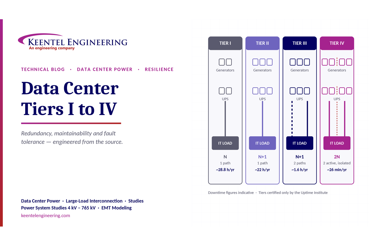
Compare Data Center Tiers I–IV, including redundancy, uptime, Tier III concurrent maintainability, Tier IV fault tolerance, UPS, generators and power design.

By SANDIP R PATEL
•
October 3, 2026
Learn how BESS supports grid stability through fast frequency response, voltage support, oscillation damping, black start, grid-forming controls and EMT studies.





