Part A — AIS vs. GIS at a Glance
Every high-voltage substation must do the same five things: carry load current continuously, interrupt fault current safely, isolate equipment for maintenance, measure current and voltage for protection and metering, and keep energized conductors safely apart from each other and from people. The difference between an air-insulated substation (AIS) and a gas-insulated substation (GIS) is how the second-to-last item — insulation — is achieved, and that one choice ripples through land, cost, construction schedule, maintenance, outage risk, environmental compliance and physical security for the next 40 to 60 years.
In an AIS, conductors are spaced apart in open air and supported on porcelain or polymer insulators. Air is free, self-restoring and easy to inspect, but it is a relatively weak insulator, so the clearances are large. In a GIS, every live part — bus, circuit breakers, disconnect and ground switches, current and voltage transformers — sits inside grounded metal enclosures filled with pressurized sulfur hexafluoride (SF6) or an SF6-free alternative gas. Pressurized SF6 insulates many times better than air at atmospheric pressure, so the same 230 kV station can shrink from several acres to a building the size of a large warehouse bay.
Neither technology is universally "better". The right answer depends on land, environment, reliability targets, outage tolerance, maintenance capability, regulatory exposure and life-cycle cost. This guide gives Keentel Engineering's engineering view of the trade-off for US projects: utility transmission substations, data center and large-load campuses, and renewable and storage interconnections from 69 kV to 500 kV.
The comparison in one table
| Attribute | Air-insulated substation (AIS) | Gas-insulated substation (GIS) |
|---|---|---|
| Insulating medium | Atmospheric air plus porcelain or polymer insulators | SF6 (typically 0.4–0.7 MPa absolute) or SF6-free gas mixtures inside grounded enclosures |
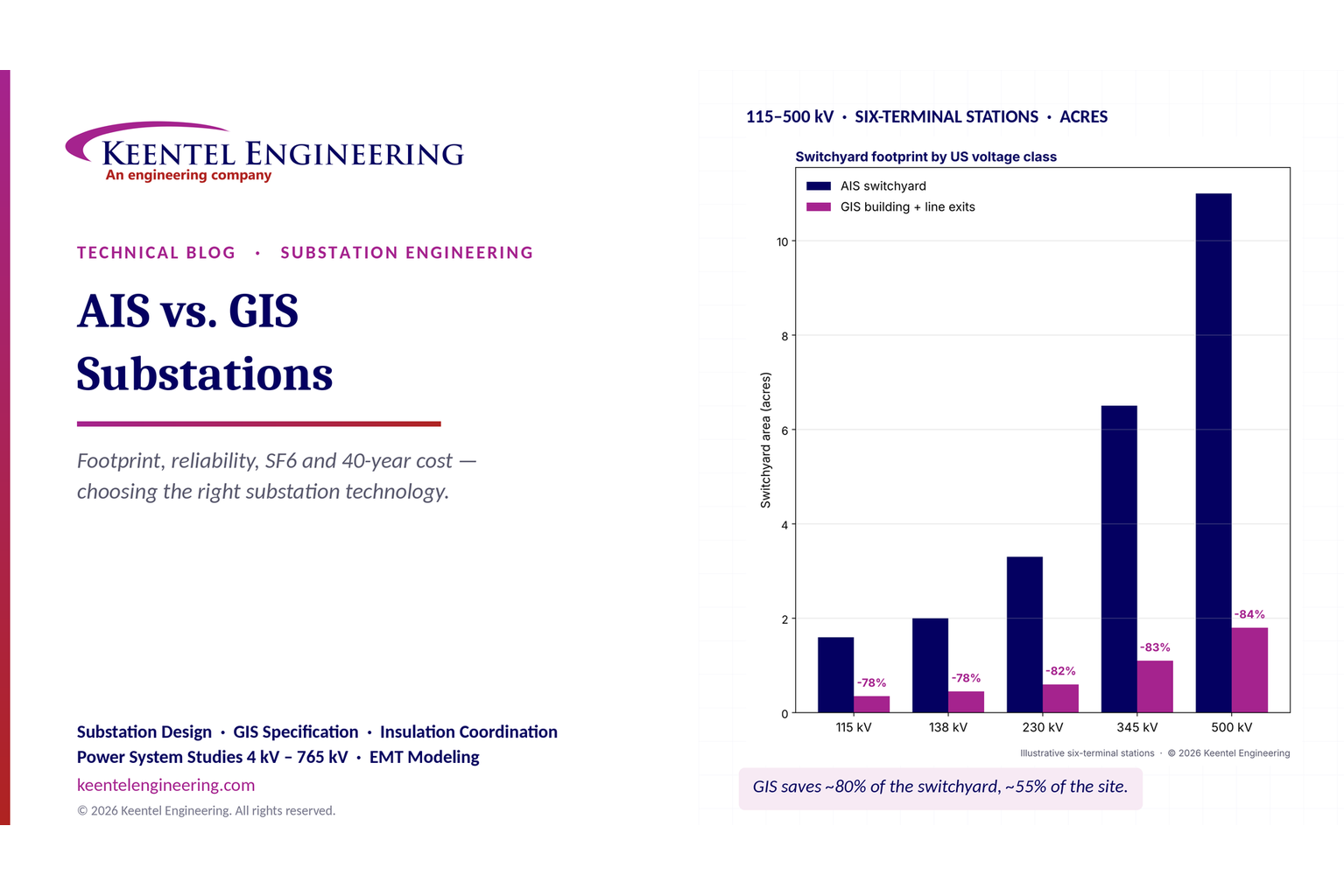
| Switchyard footprint (230 kV, six terminals) | About 3–3.5 acres inside the fence | About 0.5–0.7 acre (building plus line exits) — roughly 80% less switchyard area |
| Whole-site footprint | Reference | Typically 40–60% less, because transformers, roads, control house, stormwater and setbacks remain |
| Installed equipment cost | Lower (reference) | Typically 1.3–2× AIS for the switchgear, before land |
| Exposure to weather, contamination, wildlife | High; mitigated by creepage, coatings, washing and animal guards | Low for live parts; bushings, cable terminations and control cabinets remain exposed |
| Routine maintenance | Frequent, simple, visual, done by utility crews | Infrequent; gas monitoring, partial-discharge checks, specialized internal work |
| Major-failure frequency | Higher per bay | Lower per bay |
| Repair time after a major failure | Typically days (swap a breaker or insulator) | Typically weeks to months (gas handling, factory parts, specialist crews) |
| Expansion | Easy if land is reserved | Must be planned (extension flanges, matching vendor interfaces) |
| Environmental issue | Visual and noise impact, larger land disturbance | SF6 greenhouse-gas emissions and reporting; state phase-out rules for new equipment |
| Physical security | Large perimeter, visible equipment | Indoors, smaller perimeter; supports CIP-014 strategies |
| Typical US applications | Rural and suburban transmission substations, generation and renewable collector stations, most interconnection switchyards | Dense urban areas, data center campuses with constrained land, coastal or industrial contamination, underground cable terminations, offshore platforms |
What Keentel's analysis shows
Keentel Engineering compared an illustrative 230 kV, six-terminal breaker-and-a-half station built both ways. The numbers below are illustrative planning values, not quotes; every project needs a site-specific layout and estimate.
| Quantity | AIS | GIS |
|---|---|---|
| Switchyard area | 13,500 m² (3.3 acres) | 2,400 m² (0.6 acre) — 82% less |
| Whole site, including transformers, control house, roads, stormwater and setbacks | 20,300 m² (5.0 acres) | 9,200 m² (2.3 acres) — 55% less |
| Installed cost (illustrative) | $18 million | $30 million |
| Annual O&M (illustrative) | $150,000 | $90,000 |
| 40-year present value at 7%, rural land ($20,000/acre) | $20.1 million | $31.2 million |
| 40-year present value at 7%, urban land ($5 million/acre) | $45.1 million | $42.6 million |
| Land price at which the two break even | About $4.1 million per acre | |
| SF6 inventory and leakage CO2e at 0.5%/yr | — | 3,000 kg; about 350 t CO2e per year |

Figure 1. Keentel's illustrative comparison. Left: switchyard area for six-terminal stations by US voltage class, AIS versus GIS. Right: cumulative 40-year present value of a 230 kV six-terminal station for rural and urban land prices.
Five lessons
- GIS saves switchyard area, not the whole site. An 80% reduction in switchyard area becomes roughly a 50–60% reduction in total site area once transformers, roads, setbacks and stormwater are counted.
- Land price usually decides. In rural areas AIS wins by a wide margin on life-cycle cost. GIS wins when land is scarce, expensive or simply unavailable, and when the alternative is no substation at all.
- Reliability is two numbers. GIS fails less often, but takes much longer to repair. Design for restoration — spare parts, bay segregation, gas-compartment layout — matters as much as failure rate.
- Environment is now a design input. SF6 reporting, leak-rate limits and state phase-out schedules for new equipment can change the technology choice, particularly in California and northeastern states.
- Hybrid options fill the middle. Dead-tank breakers and mixed-technology switchgear modules can capture much of the GIS footprint benefit at lower cost, especially at 115–230 kV.
Engineering review of common statements about AIS and GIS
Many comparisons of the two technologies circulate in simplified form. Keentel's review of the most common claims:
| Common statement | Keentel's check |
|---|---|
| "GIS needs up to 90% less space than AIS." | Reasonable for the switchgear itself at 230 kV and above. It is not true for the whole site: power transformers, reactors, capacitor banks, the control house, access roads, stormwater ponds and property setbacks do not shrink. A 50–60% total-site saving is more typical. |
| "Example 230 kV substation: AIS about 200 m long, GIS about 40 m; GIS land requirement 10–20% of AIS." | The numbers are internally inconsistent. If both length and width scale by 40/200, the area ratio is (40/200)² = 4%, not 10–20%. Realistic values for a six-terminal 230 kV station are about 18% for the switchyard and about 45% for the whole site. |
| "AIS: easier inspection and maintenance" and "AIS: higher maintenance requirements." | Both are true but describe different things. AIS needs more frequent maintenance (insulator cleaning, connector thermography, breaker and switch servicing), but each task is simple and visible. GIS needs less frequent maintenance, but internal work requires gas handling, clean conditions and specialist crews. |
| "GIS: high reliability." | GIS has a lower major-failure frequency per bay, but its mean time to repair is much longer. Availability depends on both, and on how the station is arranged for restoration. |
| "AIS: lower reliability in harsh environments." | Only if contamination is ignored. Specific creepage distance, silicone rubber insulators, room-temperature vulcanizing (RTV) coatings, washing programs and animal mitigation give AIS good performance in most coastal, desert and industrial sites. GIS is preferred where contamination is extreme or salt fog is persistent. |
| "GIS uses SF6 gas, which has high greenhouse-gas potential." | Correct. SF6 has a 100-year global warming potential of about 23,500. In the US, emissions are reported under EPA's Greenhouse Gas Reporting Program (Subpart DD) above a nameplate threshold, and several states regulate leakage and are phasing out SF6 in new equipment. SF6-free GIS is commercially available at some US voltage classes and expanding. |
| "Typical GIS applications include renewable energy collector stations." | Uncommon in the US. Most US wind, solar and storage collector substations (34.5 kV collection stepping up to 115–345 kV) are AIS on inexpensive land. GIS is used where land, contamination, visual impact or underground cable interfaces dictate. |
| "GIS applications: offshore platforms." | Correct worldwide; offshore substations use compact GIS. In the US, offshore wind has a small number of projects and the pipeline is uncertain, so this is a niche application. |
Part B — AIS vs. GIS in Technical Depth
1. What a substation must do, and why insulation drives layout
A transmission substation is an assembly of switching and transformation equipment arranged around buses. At its core are a few equipment types that appear in both AIS and GIS:
| Function | Equipment | Notes for AIS | Notes for GIS |
|---|---|---|---|
| Carry current | Bus (rigid tubular or strain), connectors, bus supports | Aluminum tube on station post insulators or strain bus between structures | Coaxial aluminum conductor inside a grounded enclosure, supported on cast-epoxy spacers |
| Interrupt faults | Circuit breaker | Live-tank or dead-tank SF6 breakers, or vacuum at lower voltages | Enclosed SF6 or SF6-free breaker module |
| Isolate | Disconnect switches | Vertical-break, center-break, double-break or pantograph switches with visible air gap | Enclosed disconnectors with position indication or viewing windows |
| Ground for safety | Ground switches, portable grounds | Portable personal protective grounds or switch-mounted grounding blades | Maintenance ground switches and fast-acting (make-proof) ground switches |
| Measure | Current and voltage transformers | Free-standing CTs and CCVTs; bushing CTs on dead-tank breakers | Toroidal CTs around the conductor; inductive VTs; low-power instrument transformers available |
| Limit overvoltage | Surge arresters | Station-class arresters near transformers and line entrances | Enclosed arresters, plus outdoor arresters at gas-to-air bushings |
| Connect to lines and cables | Line dead-ends, cable terminations | Overhead line dead-end structures and cable terminations | Gas-to-air bushings or direct cable connections inside the enclosure |
The arrangement of this equipment — the bus configuration — sets reliability, operating flexibility and land use. Insulation sets the spacing. In AIS, minimum air clearances between phases and to ground, plus working clearances for people and vehicles, make each bay large. In GIS, the same function fits inside enclosures a fraction of a meter to about a meter in diameter.
2. Bus arrangements and what they mean for each technology
Bus arrangement is chosen for reliability and operability first, and the insulation technology second. Both AIS and GIS can implement any arrangement, but the footprint cost of adding breakers is very different.
| Arrangement | Breakers per circuit | Strengths | Weaknesses | Typical US use |
|---|---|---|---|---|
| Single bus | 1 | Simple, least cost | A bus fault or bus maintenance takes out every circuit | Distribution substations, small generator tie stations |
| Main and transfer bus | About 1 | Breaker maintenance without circuit outage (via transfer breaker) | A bus fault still drops everything; complex switching | Older 69–138 kV stations |
| Ring bus | 1 | Every circuit has two breakers; no bus to fault; economical | Opening the ring for maintenance reduces security; difficult to expand beyond about six terminals | 115–345 kV switching stations and renewable interconnections |
| Breaker-and-a-half | 1.5 | High reliability, flexible maintenance, expandable | More breakers and land | 230–500 kV transmission substations |
| Double bus, double breaker | 2 | Highest reliability; any breaker or bus can be maintained | Highest cost | Critical 345–765 kV stations, large generating stations |
Many US interconnection switchyards start as a three- or four-breaker ring and are designed for future conversion to breaker-and-a-half. With AIS, that conversion needs reserved land. With GIS, it needs reserved building space and planned extension interfaces, because GIS bays from different manufacturers do not connect without an adapter.
Reliability of arrangements is evaluated with the methods of the reliability guide for industrial and commercial power systems (IEEE 493) and utility practice: count the circuits lost for each single contingency (fault, breaker failure, stuck breaker during maintenance) and weight by frequency and duration. The arrangement often matters more than the insulation technology.
3. How GIS is built
A GIS is a modular system of grounded metal enclosures, typically cast or welded aluminum, joined by bolted flanges. Inside, conductors are held concentrically by cast-epoxy insulators.
Enclosure types. At 69 to 145 kV, three-phase-in-one-enclosure designs are common and compact. At 230 kV and above, most designs use single-phase enclosures, which eliminate phase-to-phase faults inside the enclosure and simplify the dielectric design. Some manufacturers offer three-phase designs at 230 kV.
Gas compartments. The GIS is divided into separate gas compartments by gas-tight barrier insulators. Compartment boundaries are chosen so that an internal failure or a maintenance opening affects as little of the station as possible. A well-planned layout lets a failed breaker compartment be repaired while adjacent bus sections stay in service. A poorly planned layout can force a whole bus out of service to work on a single disconnect.
Support insulators. Non-barrier (perforated) insulators support the conductor without separating gas compartments. Insulator surfaces are the most electrically stressed parts of a GIS and the most sensitive to particles and moisture.
Density monitoring. Because dielectric strength depends on gas density, not pressure alone, each compartment has a temperature-compensated density monitor with at least two stages: an alarm (refill) and a lockout or trip (block operation or isolate) level. Many modern installations add online density trending to catch slow leaks.
Interfaces. A GIS connects to the outside world through gas-to-air bushings (for overhead lines), direct cable terminations (for underground transmission cables, per the cable connection guide IEEE 1300) and direct transformer connections (oil-to-gas bushings). These interfaces are where AIS-style exposure returns: outdoor bushings still need clearances, arresters and lightning shielding.
Local control cabinets. Each bay has a local control cabinet with interlocking, position indication, density alarms and often bay control units. These cabinets carry the station's control logic and are part of the protection and control design.
Hybrid and mixed-technology switchgear. Between full AIS and full GIS sit several intermediate options:
- Dead-tank breakers with bushing CTs, which remove free-standing CTs and shrink AIS bays.
- Mixed-technology switchgear (MTS) modules, often called hybrid switchgear, which put a breaker, disconnects, ground switches and CTs for one bay into a compact gas-insulated module with air-insulated connections to the bus.
- Indoor or outdoor GIS bays added to an existing AIS, often for a new line terminal in a congested yard.
For 115–230 kV stations where land is tight but not scarce, these options can capture much of the footprint benefit at a lower cost than a complete GIS.
4. Dielectric fundamentals: why SF6 is so compact
The breakdown voltage of a gas gap depends on the product of pressure p and gap distance d (Paschen's law). For the uniform and quasi-uniform fields used in GIS, the critical reduced field strength of SF6 is about 89 kV per centimeter per bar, roughly three times that of air:

Because the critical field scales roughly linearly with pressure, filling a GIS to 4–6 bar absolute multiplies the allowable stress again. In practice, designers cannot use the full theoretical value. Field non-uniformity, conductor surface roughness, free conducting particles and insulator surfaces reduce the usable stress, so a utilization factor η of about 0.5 to 0.7 is applied:

| Absolute pressure (bar) | Theoretical critical field, SF6 (kV/mm) | Usable design stress at η = 0.6 (kV/mm) |
|---|---|---|
| 1 | 8.9 | 5.3 |
| 3 | 26.7 | 16.0 |
| 4 | 35.6 | 21.4 |
| 5 | 44.5 | 26.7 |
| 6 | 53.4 | 32.0 |
Worked example 1 — sizing a 230 kV coaxial bus
A GIS bus is a coaxial cylinder: an inner conductor of radius r1 inside a grounded enclosure of radius r2. The maximum field is at the conductor surface:

For a fixed enclosure size, the maximum field is lowest when r2/r1 = e (about 2.72). Design for the 230 kV lightning impulse withstand level of 900 kV with r1 = 81 mm:


At 5 bar absolute and η = 0.6, the usable stress is 26.7 kV/mm, giving a margin of about 2.4. The enclosure is therefore about 440 mm in diameter.
For the same 900 kV impulse in air at atmospheric pressure, with a usable stress of only about 1.8 kV/mm (3 kV/mm × 0.6), the conductor radius would need to be about 500 mm and the enclosure about 1.36 m in radius. That is not practical; AIS instead relies on large open-air gaps measured in meters. This calculation is the physics behind GIS compactness.
Moisture, particles and partial discharge
The dielectric strength of a GIS depends on cleanliness. Free metallic particles left from assembly can lift and move in the field, triggering breakdown well below the design withstand level. Moisture can condense on insulator surfaces at low temperatures and reduce surface withstand. GIS standards and specifications therefore require factory and site high-voltage tests, moisture limits (dew point) on gas fill, and partial-discharge measurement.
Ultra-high-frequency (UHF) partial-discharge monitoring, using sensors on the enclosure or barrier insulators, detects the 300 MHz to 3 GHz signals produced by discharges from particles, protrusions and floating electrodes. It is the most effective early-warning tool for internal GIS defects and is commonly specified for 230 kV and above.
5. Insulation levels for US voltage classes
Insulation coordination for both technologies follows the insulation coordination standard (IEEE 1313.1) and the arrester application guide (IEEE C62.22). The basic lightning impulse insulation level (BIL) and, at 345 kV and above, the basic switching impulse insulation level (BSL) are selected from standard values. Typical US selections:
| Nominal system voltage | Maximum system voltage | Typical AIS BIL | Typical GIS rated lightning impulse withstand | BSL (switching) |
|---|---|---|---|---|
| 69 kV | 72.5 kV | 350 kV | 325–350 kV | — |
| 115 kV | 121 kV | 550 kV | 550 kV | — |
| 138 kV | 145 kV | 650 kV | 650 kV | — |
| 230 kV | 242 kV | 900 kV (1,050 kV in high-lightning or contaminated areas) | 900–1,050 kV | — |
| 345 kV | 362 kV | 1,300 kV (1,050 kV with close arrester protection) | 1,050–1,175 kV | 825–950 kV |
| 500 kV | 550 kV | 1,800 kV (1,550 kV with close arrester protection) | 1,550 kV | 1,175 kV |
GIS is often specified at a lower impulse level than AIS for the same voltage class, because the arresters are close to protected equipment and the enclosed design is not exposed to direct strokes. However, GIS adds a phenomenon AIS does not have: very fast transient overvoltages (Section 9).
Values vary by utility standard, altitude and lightning exposure; confirm against the purchasing utility's specification and an insulation coordination study.
6. AIS design essentials
Electrical clearances
AIS clearances are set by the insulation level, altitude, and safety requirements. The National Electrical Safety Code (NESC) sets minimum clearances from energized parts to fences and to working areas (Rule 124 and associated tables), and the AIS clearance guide (IEEE 1427) gives recommended phase-to-ground and phase-to-phase electrical clearances for each BIL.
Worked example 2 — checking a 230 kV phase-to-ground clearance
Start from the required BIL of 900 kV. BIL is defined as a withstand with 10% probability of flashover, which is about 1.28 standard deviations below the 50% critical flashover voltage (CFO). With a lightning impulse standard deviation of about 3%:

For a conductor-to-structure gap under positive lightning impulse, the CFO gradient is roughly 540 to 605 kV per meter, depending on gap geometry:

That is about 61 to 68 inches before adding construction tolerances, conductor movement and altitude correction above 1,000 m (3,300 ft). Utility standards for 900 kV BIL typically land in the range of about 1.8 to 2.0 m phase-to-ground and more phase-to-phase, with rigid-bus phase spacing commonly around 4 to 4.5 m (13 to 15 ft) to allow for switch operation and maintenance access. Always confirm against IEEE 1427, the NESC and the owner's design standard.
These meter-scale gaps, multiplied across three phases, multiple bays and safe working aisles, explain why a 230 kV AIS bay is often 15 to 20 m wide and 80 to 150 m deep.
Rigid bus design
AIS rigid bus design follows the substation rigid-bus guide (IEEE 605): ampacity from a heat balance, short-circuit electromagnetic forces, wind and ice loading, vibration, thermal expansion and connector design.
Worked example 3 — ampacity of a tubular aluminum bus
The steady-state heat balance for an outdoor bus is:

so:

Take a 4-inch Schedule 40 tube in 6063-T6 aluminum (53% IACS), 40 °C ambient, 30 °C allowable rise (70 °C conductor), 0.61 m/s (2 ft/s) crosswind, emissivity and solar absorptivity of 0.5 and full sun of 1,000 W/m².
| Quantity | Value |
|---|---|
| Outside diameter | 114.3 mm |
| Conductor cross-section | 2,048 mm² |
| AC resistance at 70 °C (including about 2% skin effect) | 1.90 × 10⁻⁵ Ω/m |
| Forced convection loss qc | 76 W/m |
| Radiation loss qr | 43 W/m |
| Solar gain qs | 57 W/m |
| Ampacity | about 1,810 A |
A 5-inch Schedule 40 tube carries about 2,200 A and a 6-inch Schedule 40 tube about 2,640 A under the same assumptions. To reach 3,000 A, the designer would move to a heavier wall, a higher-conductivity alloy (6101), a higher allowable temperature where permitted, or paralleled conductors.
A GIS bay at 230 kV is commonly rated 3,000 A or 4,000 A continuous in an enclosure the size worked out above. The rating is a type-tested value that already accounts for enclosure currents, which in single-phase designs carry induced currents nearly equal to the conductor current.
Lightning shielding
AIS equipment must be shielded from direct lightning strokes by shield wires and masts, designed with the rolling-sphere or empirical methods of the direct-stroke shielding guide (IEEE 998). In GIS, the enclosure itself is the shield; only outdoor bushings, line entrances and transformer connections need shielding.
Contamination performance
AIS insulators must provide enough specific creepage distance for the site's contamination class. Coastal, desert, agricultural and industrial sites in the US may need 25 to 31 mm/kV or more of creepage (phase-to-phase basis), silicone rubber housings, RTV coatings or periodic washing. Most "harsh environment" AIS problems are solved by correct insulator selection rather than by switching to GIS.
7. GIS design essentials
Standards
US GIS practice is anchored in the IEEE C37.122 family: the standard for gas-insulated substations rated above 52 kV (IEEE C37.122), its application guide (IEEE C37.122.1), the guide for SF6 gas handling (IEEE C37.122.3), and the guide to specifications for gas-insulated substation equipment (IEEE C37.123). Circuit breaker ratings follow the C37.04, C37.06 and C37.09 series, and seismic qualification follows the substation seismic design guide (IEEE 693).
Ratings to specify
| Rating | Typical 230 kV GIS values | Comment |
|---|---|---|
| Rated maximum voltage | 245 kV class (242 kV US maximum system voltage) | Confirm the US rating designation in the specification |
| Lightning impulse withstand | 900 or 1,050 kV | Per insulation coordination study |
| Continuous current, bus | 3,000 or 4,000 A | Size for future, not just initial, load |
| Continuous current, bay | 2,000–3,000 A | |
| Short-circuit current | 50 or 63 kA, 3 s | Verify against a 10- to 20-year short-circuit forecast |
| Gas leak rate | ≤ 0.5% per year per compartment (many specifications now require ≤ 0.1%) | Affects emissions and reporting |
| Seismic | IEEE 693 moderate or high level | Site dependent |
Very fast transient overvoltages (VFTO)
When a GIS disconnector opens or closes on a trapped charge, repeated restrikes across its slowly moving contacts launch steep traveling waves with rise times of a few to tens of nanoseconds. These waves reflect within the GIS, producing very fast transient overvoltages that can approach 2 per unit at 345 kV and above. VFTO can stress transformer windings directly connected to the GIS, secondary equipment and the GIS's own insulation. Mitigations include disconnector design (damping resistors), layout and, for direct transformer connections, transformer specification and transient studies. VFTO is usually a design concern at 345 kV and above; it should still be considered at 230 kV for direct-connected transformers.
Transient enclosure voltage and grounding
The same fast transients induce transient enclosure voltage (TEV) — short, high-frequency voltage rises on enclosures, especially at gas-to-air bushings and cable terminations where the coaxial structure ends. TEV is typically a few kilovolts to tens of kilovolts with nanosecond rise times. It is not usually a shock hazard in the conventional sense but can cause startle reactions, sparking at flanges and interference with secondary equipment. The mitigation is short, wide, low-inductance bonding of enclosures to the ground grid at frequent intervals, and bonding across insulated flanges where provided.
8. Grounding and step and touch voltage — AIS outdoors vs. GIS indoors
Both technologies require a ground grid designed to the substation grounding guide (IEEE 80). The GIS case has one feature that surprises some designers: moving indoors removes the crushed-rock surface layer that protects people in an outdoor AIS.
Worked example 4 — ground potential rise and tolerable touch voltage
Suppose the maximum grid current (after current division) is 8 kA and the grid resistance is 0.5 Ω:

The tolerable touch voltage for a 70 kg person is:

where Cs is the surface-layer derating factor, ρs the surface-layer resistivity and ts the fault duration. (The 50 kg criterion uses 0.116 instead of 0.157 and is more conservative.) For a fault duration of 0.5 s:
| Surface | ρs (Ω·m) | Cs | Tolerable touch voltage (70 kg, 0.5 s) |
|---|---|---|---|
| Outdoor AIS with 100 mm crushed rock | 3,000 | 0.7 | about 920 V |
| Indoor GIS floor, concrete (wet, conservative) | 100 | 1.0 | about 255 V |
The indoor tolerable touch voltage is more than three times lower. GIS buildings therefore need a dense equipotential grid in the floor slab, bonding of reinforcing steel, bonding of every enclosure flange and support, and careful treatment of the transition to the outdoor yard. The design method is the same IEEE 80 method; the inputs differ.
9. Reliability: failure frequency vs. repair time
Industry reliability surveys for high-voltage switchgear consistently show that GIS has a lower major-failure frequency per bay than equivalent AIS, while repair of a major GIS failure takes much longer. A major AIS failure — a breaker, CT or insulator — can often be fixed in days by replacing the component, sometimes from utility spares. A major GIS failure requires gas recovery, opening the compartment under clean conditions, a factory part and a specialist crew, then gas refill, drying and high-voltage testing. Weeks to months is typical.
Worked example 5 — unavailability of one bay
Availability depends on both frequency and duration:

Using illustrative values:
| Technology | Major failures per 100 bay-years | λ (per bay-year) | MTTR | Unavailability U | Hours out per bay-year |
|---|---|---|---|---|---|
| AIS bay | 0.5 | 0.005 | 5 days | 6.8 × 10⁻⁵ | 0.6 h |
| GIS bay | 0.2 | 0.002 | 45 days | 2.5 × 10⁻⁴ | 2.2 h |
In this example the GIS bay fails less than half as often but is unavailable about 3.6 times longer per year on average. The conclusions:
- Bus arrangement matters more than technology. In a breaker-and-a-half or double-breaker GIS, a failed bay can be isolated while circuits stay in service through the other breakers.
- Gas-compartment layout determines how much is taken out. Specify compartment boundaries so that repairing any single compartment does not require removing both main buses from service.
- Spares shorten MTTR. For GIS, a strategic spare breaker module, a spare disconnector, spare barrier insulators and a spare gas cart can cut repair time from months to weeks.
- Vendor support is part of reliability. A GIS fleet is tied to its manufacturer's service network for its whole life.
These values are illustrative; use utility and survey data for a specific study.
10. SF6, emissions and the regulatory landscape
Why SF6 matters
SF6 is an excellent insulating and arc-quenching gas — chemically stable, non-flammable and non-toxic in its pure state. But it is the most potent greenhouse gas assessed by the Intergovernmental Panel on Climate Change, with a 100-year global warming potential of about 23,500 (IPCC Fifth Assessment Report; earlier inventories used 22,800), and an atmospheric lifetime of more than 1,000 years. Arcing produces toxic decomposition products, so gas handling and internal work require specific procedures and personal protective equipment (IEEE C37.122.3).
Worked example 6 — annual leakage emissions
A 230 kV, six-terminal breaker-and-a-half GIS may contain on the order of 3,000 kg of SF6 (illustrative; varies widely by design). At a leak rate of 0.5% per year:


That is similar to the annual emissions of about 75 passenger vehicles. At a 0.1% specified leak rate, emissions fall to about 70 t CO2e per year. Handling losses during maintenance and end-of-life recovery can exceed steady leakage if poorly controlled.
Federal reporting
EPA's Greenhouse Gas Reporting Program, Subpart DD (40 CFR Part 98), requires facilities whose total nameplate capacity of SF6 and PFC-containing equipment exceeds 17,820 lb (about 8,080 kg) to report annual emissions. EPA has updated its global warming potential values over time; confirm the value applicable to the reporting year. EPA also runs a voluntary SF6 Emission Reduction Partnership for electric power systems.
State rules
States are moving faster than federal rules:
- California regulates SF6 in gas-insulated equipment, with declining emission-rate limits and a phased prohibition on SF6 in new equipment, by voltage and short-circuit rating, beginning in the mid-2020s with lower-voltage classes and extending to transmission classes in the early 2030s, with an exemption process where SF6-free equipment is not available.
- Massachusetts and New York have adopted SF6 emission limits and reporting requirements, and other states are considering similar rules.
Because these rules are being amended, owners should confirm current schedules for each project. For a new GIS in California or the Northeast, the SF6-free question must be answered at concept stage, not at procurement.
SF6-free alternatives
Three families of alternatives are commercially available or emerging:
- Fluoronitrile-based mixtures (a fluoronitrile with CO2 and O2), with a global warming potential of a few hundred and dielectric strength close to SF6 at somewhat higher pressure, now available in GIS at transmission voltages including 145 kV and above, with growing availability at 245 kV and higher.
- Fluoroketone-based mixtures, used mainly at medium voltage.
- Clean dry air or nitrogen insulation with vacuum interrupters, available today at 72.5 kV and 145 kV classes and moving upward.
Alternative gases change the design: higher fill pressure or larger enclosures, different gas-handling equipment and procedures, different density-monitor settings, and in some cases a lower interrupting rating per breaker. Request type-test reports for the US ratings needed (voltage class, short-circuit current, X/R and transient recovery voltage duty) rather than relying on catalog data.
11. Footprint, land and siting
Worked example 7 — the footprint of a 230 kV six-terminal station
Consider a 230 kV breaker-and-a-half station with six terminals (four lines and two transformers).
AIS. Three diameters of three breakers each, two main buses, line dead-end structures, free-standing CTs and CCVTs, shield masts, fencing, roads inside the yard and working clearances. A practical fenced switchyard is about 150 m × 90 m:

GIS. A building of roughly 45 m × 18 m houses the switchgear and a crane. Adding gas-to-air bushings with arresters for four overhead lines and two transformer connections brings the switchgear-related area to about:


The rest of the site does not shrink. Two transformers with oil containment and fire separation (about 1,000 m²), a control house (about 300 m²), access road and parking (about 1,500 m²) and stormwater management and property setbacks (about 4,000 m²) add about 6,800 m² in both cases:
| Item | AIS (m²) | GIS (m²) |
|---|---|---|
| Switchgear area | 13,500 | 2,400 |
| Transformers, containment, separation | 1,000 | 1,000 |
| Control house | 300 | 300 |
| Roads and parking | 1,500 | 1,500 |
| Stormwater and setbacks | 4,000 | 4,000 |
| Total | 20,300 (5.0 acres) | 9,200 (2.3 acres) |
| Saving | — | 55% |
Checking the common simplification. A claim that an AIS is "about 200 m long" and a GIS "about 40 m long", with GIS needing "10–20% of the land", is not consistent. Scaling both dimensions by 40/200 gives an area ratio of:

Real projects land between these figures: about 15–20% for the switchgear area alone and 40–50% for the full site.
Siting factors beyond area
- Shape. A GIS building fits irregular urban parcels and can sit in the basement or ground floor of a mixed-use building. An AIS needs a rectangular, level yard.
- Height and visual impact. AIS structures at 230 kV are often 15–20 m tall. A GIS building can be designed to blend with neighbors (see the guide on community acceptance, IEEE 1127).
- Noise. Transformers dominate noise in both cases.
- Underground cables. Where lines arrive as underground cables, GIS with direct cable terminations avoids outdoor cable terminations and their structures.
- Flooding. GIS buildings must have equipment above the design flood elevation; outdoor AIS can be raised on fill but is exposed.
12. Maintenance, testing and lifecycle
| Activity | AIS | GIS |
|---|---|---|
| Visual inspection | Monthly to quarterly; everything visible | Monthly; most live parts are not visible |
| Infrared thermography | Annual or more, very effective on connectors and switches | Limited to external connections, bushings and enclosure hot spots |
| Insulator cleaning or coating | Periodic in contaminated areas | Bushings only |
| Breaker maintenance | Time-based or condition-based, typically every 6–12 years for SF6 dead-tank and live-tank breakers | Condition-based; many designs specify internal inspection after a set number of operations or 20–25 years |
| Disconnect switch maintenance | Frequent adjustments and lubrication; alignment, ice and corrosion issues | Enclosed mechanisms; fewer adjustments |
| Gas monitoring | Breaker density monitors only | Every compartment; leak detection, moisture, decomposition product analysis |
| Partial-discharge monitoring | Not applicable | UHF periodic or continuous, recommended at 230 kV and above |
| Skills | Utility substation crews | Manufacturer or specialist crews for internal work; certified gas handlers |
NERC requirements
For Bulk Electric System facilities, the technology does not change the NERC obligations:
- PRC-005-6 requires a protection system maintenance program covering protective relays, communications, voltage and current sensing devices, station DC supply and control circuitry — including the CTs and VTs inside a GIS. GIS instrument transformers cannot be inspected visually, so the program relies on in-service current and voltage comparisons and relay alarms.
- FAC-008 facility ratings must reflect the most limiting series element. In GIS, that is often a bay rating or an outdoor bushing; in AIS, it is frequently a disconnect switch, connector or CT ratio.
- CIP-014 physical security for applicable transmission stations favors indoor GIS, with a smaller perimeter and no line-of-sight to critical equipment, though outdoor transformers and bushings remain exposed.
Worker safety
Arc-flash and shock-protection programs follow NFPA 70E. NFPA 70B (now a standard, not a recommended practice) sets maintenance program requirements for electrical equipment, though utility generation, transmission and distribution facilities are generally outside its scope; many owners still use its condition-based principles. GIS internal faults can rupture an enclosure: specify pressure-relief devices and internal-arc classification, and route pressure relief away from work areas.
13. Life-cycle cost
The installed-cost premium for GIS varies by voltage class, market and scope. Typical ranges for the switchgear, excluding land and transformers, are 1.3–2× AIS. Life-cycle comparisons should include:

with the uniform-series factor:

Worked example 8 — 40-year present value
Using the six-terminal 230 kV example (illustrative inputs):
| Input | AIS | GIS |
|---|---|---|
| Installed cost | $18.0 M | $30.0 M |
| Site area | 5.02 acres | 2.27 acres |
| Annual O&M | $0.15 M | $0.09 M |
| PV of O&M (× 13.33) | $2.0 M | $1.2 M |
| Land price | AIS PV | GIS PV | Lower cost |
|---|---|---|---|
| $20,000 per acre (rural) | $20.1 M | $31.2 M | AIS by about $11 M |
| $3 million per acre (suburban industrial) | $35.0 M | $38.0 M | AIS by about $3 M |
| $5 million per acre (urban core) | $45.1 M | $42.6 M | GIS by about $2.5 M |
The break-even land price is:

Three things often tip the balance further toward GIS:
- Availability of land at all. A data center campus may have no room for a 5-acre AIS without giving up a data hall worth far more than the land.
- Schedule. Permitting a smaller footprint or an enclosed building can be faster in dense jurisdictions.
- Outage and environmental costs. Contamination flashovers, wildlife outages and storm exposure are real costs for AIS in some locations.
And three things tip it toward AIS:
- Repair time risk for a critical single-ended station.
- SF6 costs and regulation, including leak repair, reporting and future phase-out.
- Expansion flexibility where land is cheap.
14. Applications by sector
Utility transmission substations
AIS remains the default for most US transmission substations outside dense urban areas. GIS is chosen for urban load centers, substations at underground cable transitions, contaminated coastal and industrial sites, and stations where a large AIS expansion is impossible.
Data center and large-load campuses
Large-load campuses of 300 MW to more than 1 GW are now requesting 230–500 kV service. A dedicated owner substation inside the campus competes with data halls for land. GIS or hybrid switchgear can free several acres, and an indoor GIS supports physical security and campus aesthetics. The trade-off is repair time: a campus served by a single GIS bus arrangement should use breaker-and-a-half or double-breaker configurations, segregated gas compartments and spares to avoid a long outage of its interconnection.
Renewable and storage interconnections
US solar, wind and storage collector substations — 34.5 kV collection stepping up to 115–345 kV — are overwhelmingly AIS, because land is inexpensive and the facilities are rural. GIS appears where a project shares a constrained utility switchyard, in coastal salt-fog zones, or where the interconnecting utility requires it. Hybrid breaker modules are increasingly used in utility-owned interconnection switchyards to fit additional terminals.
Offshore wind
Offshore wind substations use compact GIS on platforms, with onshore substations often GIS as well because of coastal land constraints. US offshore wind development has a limited number of projects and an uncertain pipeline, so this remains a niche for US owners.
15. A decision framework
Keentel uses a structured comparison rather than a rule of thumb:
- Define the arrangement first. Choose ring, breaker-and-a-half or double breaker based on reliability and operating needs.
- Lay out both technologies. Draw the AIS and GIS (and a hybrid option) at concept level on the actual parcel, including transformers, roads, stormwater and setbacks.
- Check feasibility. Does AIS fit at all? Are line and cable routes compatible?
- Evaluate environment. Contamination class, lightning, seismic zone, flood elevation, wildlife.
- Assess regulation. SF6 rules for the state, emissions reporting, local zoning and noise.
- Model reliability. Failure frequency, MTTR and spares for each option and arrangement.
- Compute life-cycle cost. Including land value at its highest alternative use.
- Consider operations. The owner's maintenance capability, vendor support and future expansion.
- Decide and document. Record the basis so that later design decisions remain consistent.
16. Key takeaways
- Insulation medium is the only fundamental difference, but it changes everything else: footprint, cost, maintenance, reliability profile and environmental exposure.
- GIS saves about 80% of switchyard area at 230 kV but typically 50–60% of whole-site area.
- Rural land favors AIS by a wide margin; urban land above roughly $4 million per acre, or no land at all, favors GIS.
- GIS fails less often but takes much longer to repair; arrangement, compartment layout and spares control availability.
- SF6 emissions, reporting and state phase-outs must be addressed at concept stage; SF6-free options are available at some US voltage classes and expanding.
- Hybrid and mixed-technology switchgear often provides the best balance at 115–230 kV.
17. How Keentel Engineering helps
Keentel Engineering supports utilities, data center developers, industrial owners and renewable and storage developers with substation engineering from 69 kV to 500 kV.
| Service | Keentel scope | Outcome |
|---|---|---|
| Technology selection | AIS, GIS and hybrid concept layouts on the real parcel, life-cycle cost, reliability and regulatory comparison | A defensible, documented technology decision |
| Substation physical design | Bus arrangements, IEEE 605 rigid bus, IEEE 1427 clearances, IEEE 998 shielding, structures and foundations coordination | Construction-ready AIS designs |
| GIS specification and integration | IEEE C37.122/C37.123-based technical specifications, building and crane requirements, cable and bushing interfaces, compartment layout review | GIS procured to the owner's needs |
| Insulation coordination | BIL/BSL selection, arrester placement, VFTO and transient studies for GIS–transformer connections | Insulation levels that are safe and economical |
| Grounding and safety | IEEE 80 grid design, indoor GIS equipotential design, TEV mitigation, step and touch analysis | Safe stations indoors and out |
| Protection and control | Bus, line and transformer protection, local control cabinets, interlocking, SCADA | Integrated, testable P&C |
| Interconnection and large-load support | Utility requirements, FAC-001/FAC-002 coordination, facility ratings (FAC-008), CIP-014 considerations | Interconnections that pass review the first time |
| Owner's engineering and commissioning | Factory acceptance tests, site high-voltage and partial-discharge tests, gas handling oversight, PRC-005-6 program setup | Stations that energize on schedule |
Why clients choose Keentel Engineering
- Technology-neutral advice: we design AIS, GIS and hybrid stations and recommend what fits the site, not what is easiest to draw.
- Power systems and physical design together: insulation coordination, grounding, protection and layout come from one team.
- US practice: IEEE, NESC, NEC, NFPA and NERC requirements built in from concept to commissioning.
- Large-load and renewable experience: data center campuses, solar, wind and storage interconnections from 69 kV to 500 kV.
- Licensed professional engineering: a Florida-registered firm with offices in Tampa, Austin, Sacramento and Baltimore, supporting projects nationwide.
Planning a new substation or deciding between AIS, GIS and hybrid switchgear? Talk to Keentel Engineering at (813) 389-7871, contact@keentelengineering.com, or book a 15-minute scoping call at calendly.com/keentel-engineering/15min.
Part C — Case Studies
The following are illustrative composite scenarios based on conditions typical of US substation projects. They show how Keentel Engineering approaches AIS and GIS decisions; site details are generalized and figures are rounded.
Case Study 1 — A data center campus that could not afford the land
Situation. A hyperscale developer in the Mid-Atlantic planned a 600 MW campus served at 230 kV from two utility lines, with four 230/34.5 kV transformers feeding the campus distribution. The utility's standard AIS breaker-and-a-half switchyard, plus the owner's transformer yard, needed about 9 acres. The parcel was zoned for data center use with land valued at about $2.5 million per acre, and every acre of substation displaced roughly 12 MW of data hall capacity.
Analysis. Keentel laid out three options on the real parcel: utility-standard AIS, full indoor GIS, and an AIS transformer yard with a GIS switching building. The GIS options reduced the substation area to about 3.5 acres. On land value alone, the full-GIS option cost about $9 million more installed but freed about 5.5 acres ($13.8 million) — and the recovered area supported a further data hall, worth far more than the land. The reliability review showed that a single 230 kV GIS bus failure would take months to repair. Keentel therefore specified breaker-and-a-half with gas-compartment boundaries arranged so that either main bus could be repaired with all four transformers in service, plus a spare breaker module and spare barrier insulators held on site. Because the indoor floor lowered the tolerable touch voltage to about a quarter of the outdoor value, the building received a bonded rebar mat and an equipotential grid tied to the yard grid.
Engineered solution. A 230 kV GIS switching building with six bays, gas-to-air bushings for the two utility lines, direct oil-to-gas connections to two of the transformers and cable connections to the other two. Specifications required a leak rate of 0.1% per year per compartment, continuous density trending and UHF partial-discharge monitoring. The utility accepted the GIS after a design review of interlocking, metering and its protection standards.
Outcome. The campus gained one additional data hall within the same parcel. The substation was energized on schedule, and SF6 emissions in the first reporting year were well below the specified rate.
Case Study 2 — Coastal flashovers at a 138 kV AIS
Situation. A Gulf Coast utility had repeated contamination flashovers at a 138 kV AIS ring-bus substation about a half-mile from the shoreline. Outages clustered in early-morning fog after dry, windy periods. The utility's planners proposed replacing the station with GIS at an estimated cost of more than $14 million.
Analysis. Keentel measured equivalent salt deposit density on sample insulators and classified the site as very heavy contamination. The existing porcelain insulators provided about 20 mm/kV of specific creepage distance (phase-to-phase basis), well below what the contamination class required. Flashover locations correlated with station post insulators and CT housings on the windward side. A GIS option would eliminate most exposed insulation but keep six outdoor bushings, and the land was not constrained.
Engineered solution. Keentel recommended an AIS retrofit: silicone rubber station post insulators with extended creepage, RTV coating on equipment bushings that could not be replaced economically, replacement of free-standing CTs with dead-tank breakers carrying bushing CTs, and a seasonal live-line washing program. Surge arresters were replaced with polymer-housed units of matching creepage.
Outcome. The retrofit cost about one-fifth of the GIS estimate. In the three years after completion the station had no contamination flashovers, and the utility adopted the creepage and housing specification as its coastal standard.
Case Study 3 — Choosing SF6-free GIS for a constrained interconnection
Situation. A battery storage developer in California needed a 115 kV interconnection switching station adjacent to an existing utility substation on a narrow parcel between a highway and a flood channel. A four-breaker AIS ring did not fit with required setbacks and stormwater basins. The project faced the state's phase-out of SF6 in new gas-insulated equipment.
Analysis. Keentel compared three options: a compact AIS ring with dead-tank breakers (did not fit), SF6 GIS (required an exemption request and future reporting) and SF6-free GIS using a vacuum interrupter with clean-air insulation. The SF6-free option was available at the 115 kV class with the required 40 kA short-circuit rating, but it had larger enclosures and a higher fill pressure. Keentel verified type tests against the US ratings and transient recovery voltage duty, checked the building dimensions, and confirmed that the higher operating pressure did not change the building's pressure-relief design.
Engineered solution. A four-breaker ring in an SF6-free GIS building, with gas-to-air bushings to the utility tie and cable terminations to the storage collector substation. Keentel designed the grounding with a bonded floor grid, coordinated protection with the utility's standards, and documented facility ratings for the interconnection agreement.
Outcome. The station fit the parcel with all setbacks, avoided SF6 inventory and reporting entirely, and received utility acceptance without an exemption request. The storage facility reached commercial operation on its contract date.


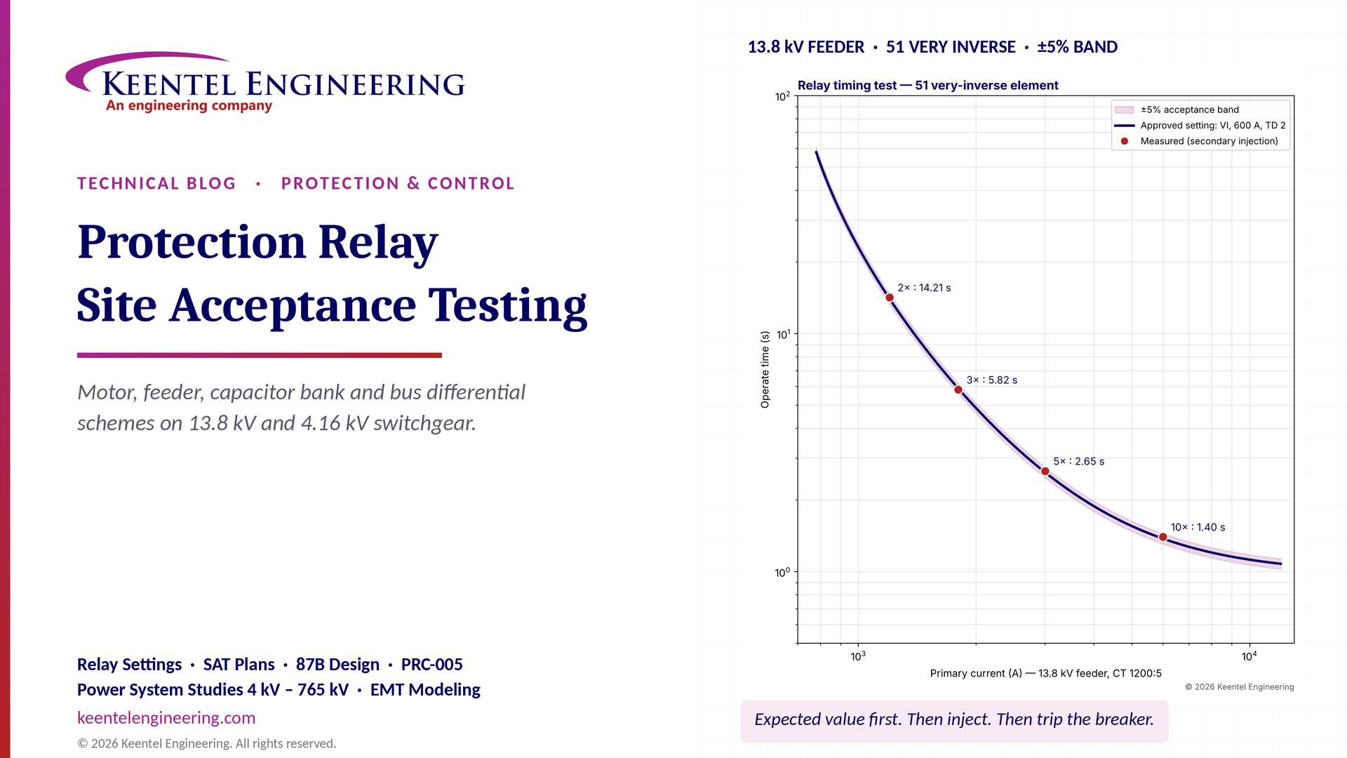
Protection relay site acceptance testing (SAT) guide covering CT/VT checks, secondary injection, motor relays, 87B bus differential and IEEE/NETA standards.

Understand SPP HILL requirements, HDPS interconnection studies, voltage and frequency ride-through, EMT modeling, weak-grid screening, and compliance.
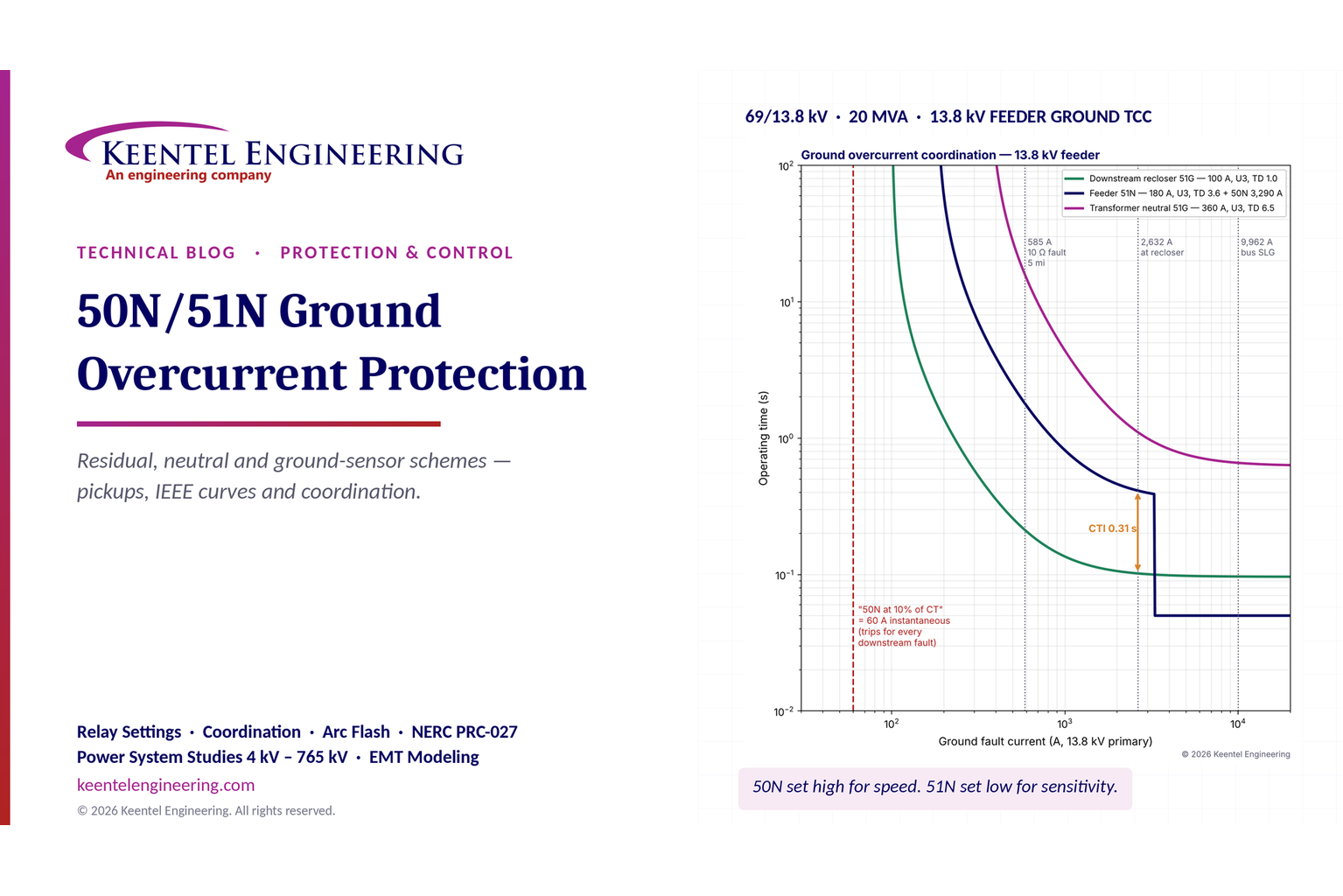
Learn 50N/51N ground overcurrent protection, relay settings, CT connections, IEEE curves, TCC coordination and ground fault protection for substations.
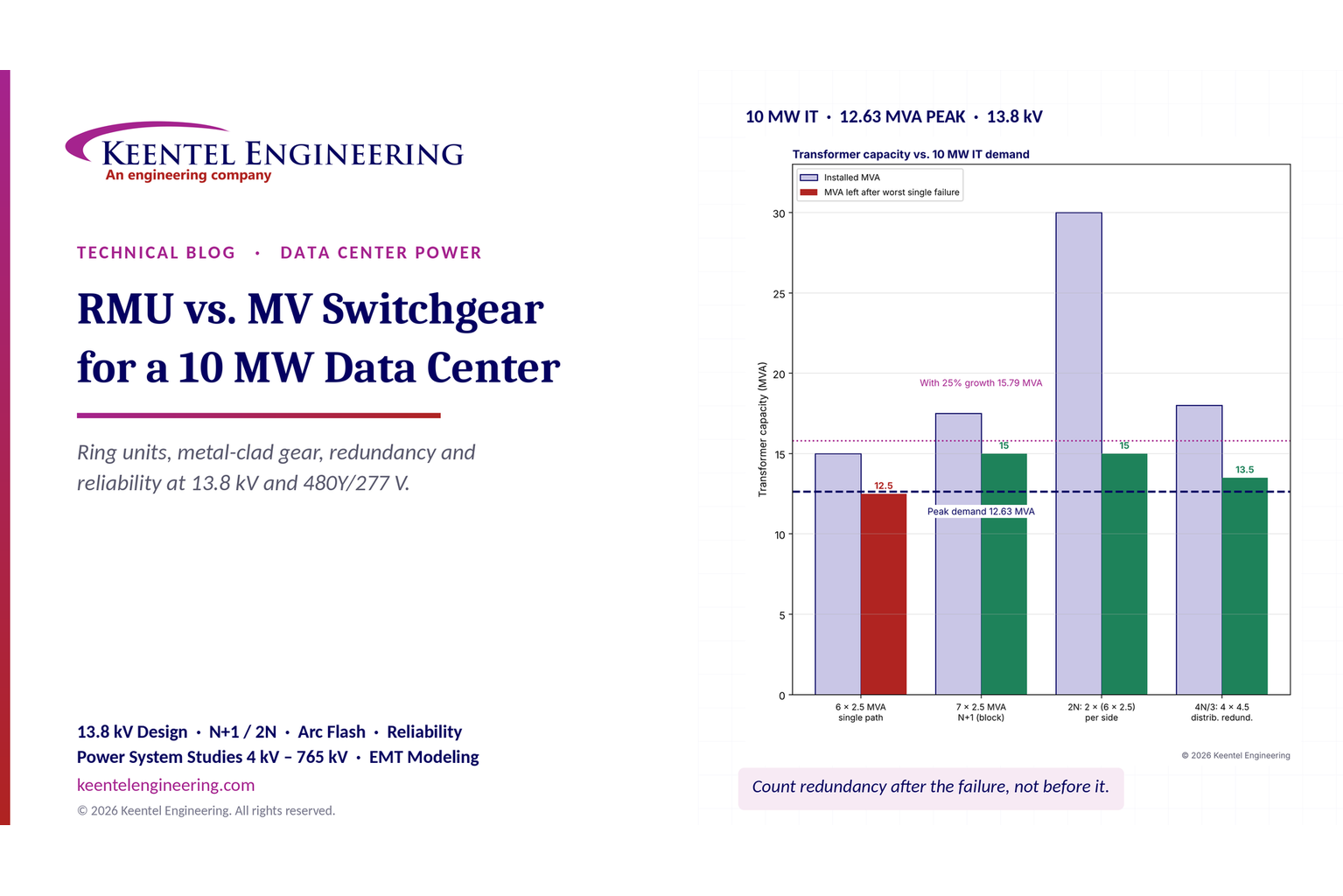
Compare RMU vs. MV switchgear for a 10 MW data center. Explore 13.8 kV design, transformer sizing, N+1/2N redundancy, arc flash and reliability.
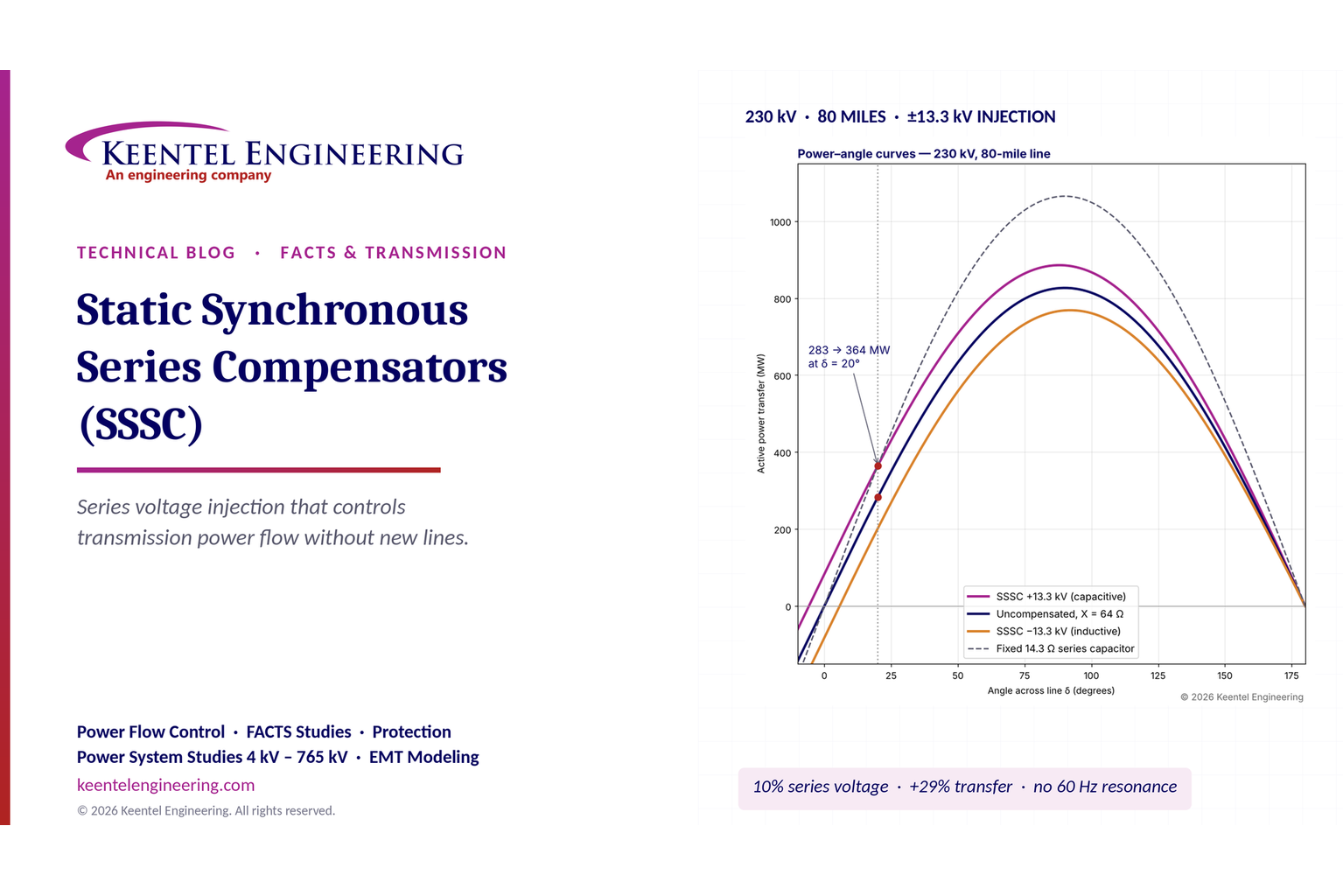
Learn how static synchronous series compensators (SSSC) control transmission power flow, improve grid stability and support FACTS applications, with examples.

Explore what's inside a data center rack, from servers and switches to PDU sizing, UPS, A/B redundancy, cooling and power design for high-density AI racks.
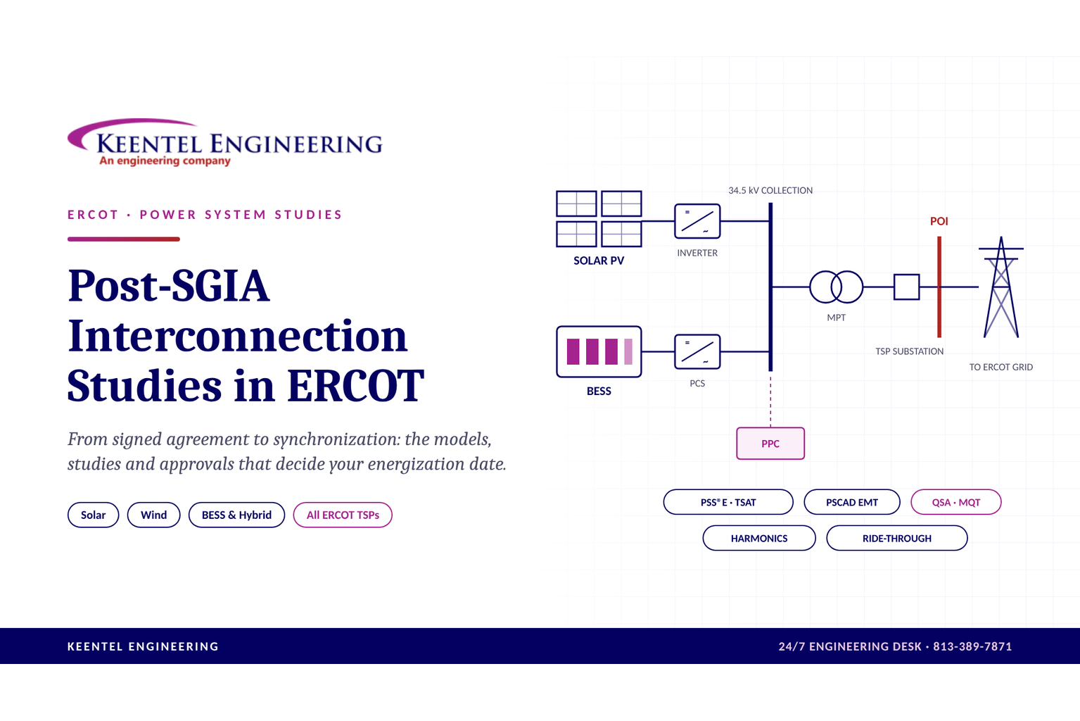
Explore post-SGIA interconnection studies in ERCOT, including PSCAD, PSS/E, QSA, model validation, TSP approvals and solar, wind and BESS commissioning.
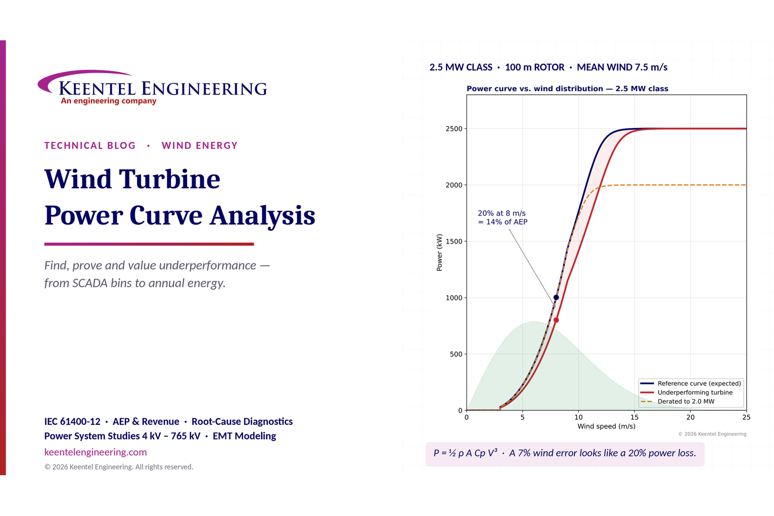
Learn wind turbine power curve analysis using SCADA data, IEC 61400-12, AEP calculations and diagnostics to identify underperformance and energy losses.
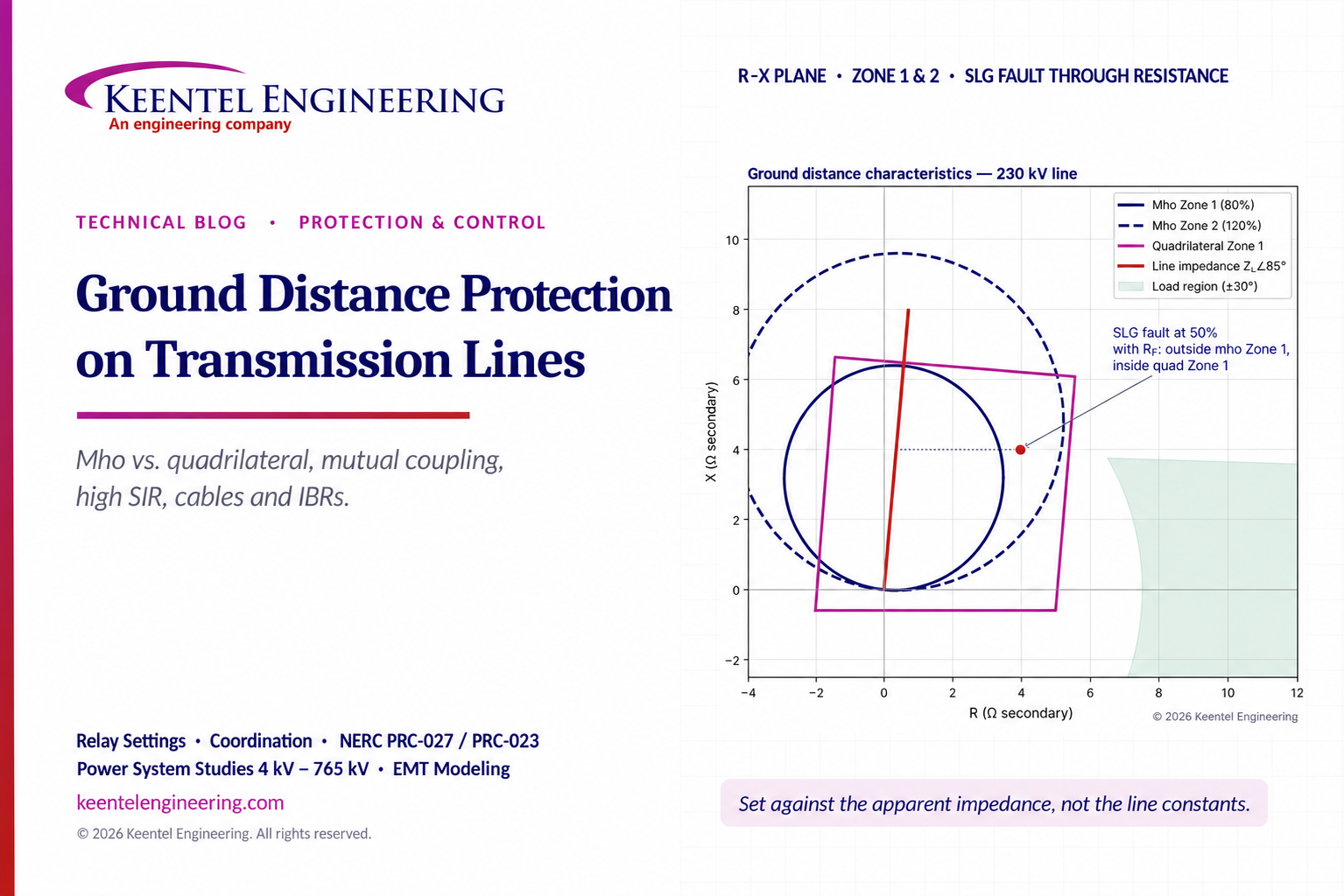
Ground distance protection guide comparing mho vs quadrilateral relays, mutual coupling, high SIR, CVT transients, IBRs and transmission line settings.