Key Takeaways
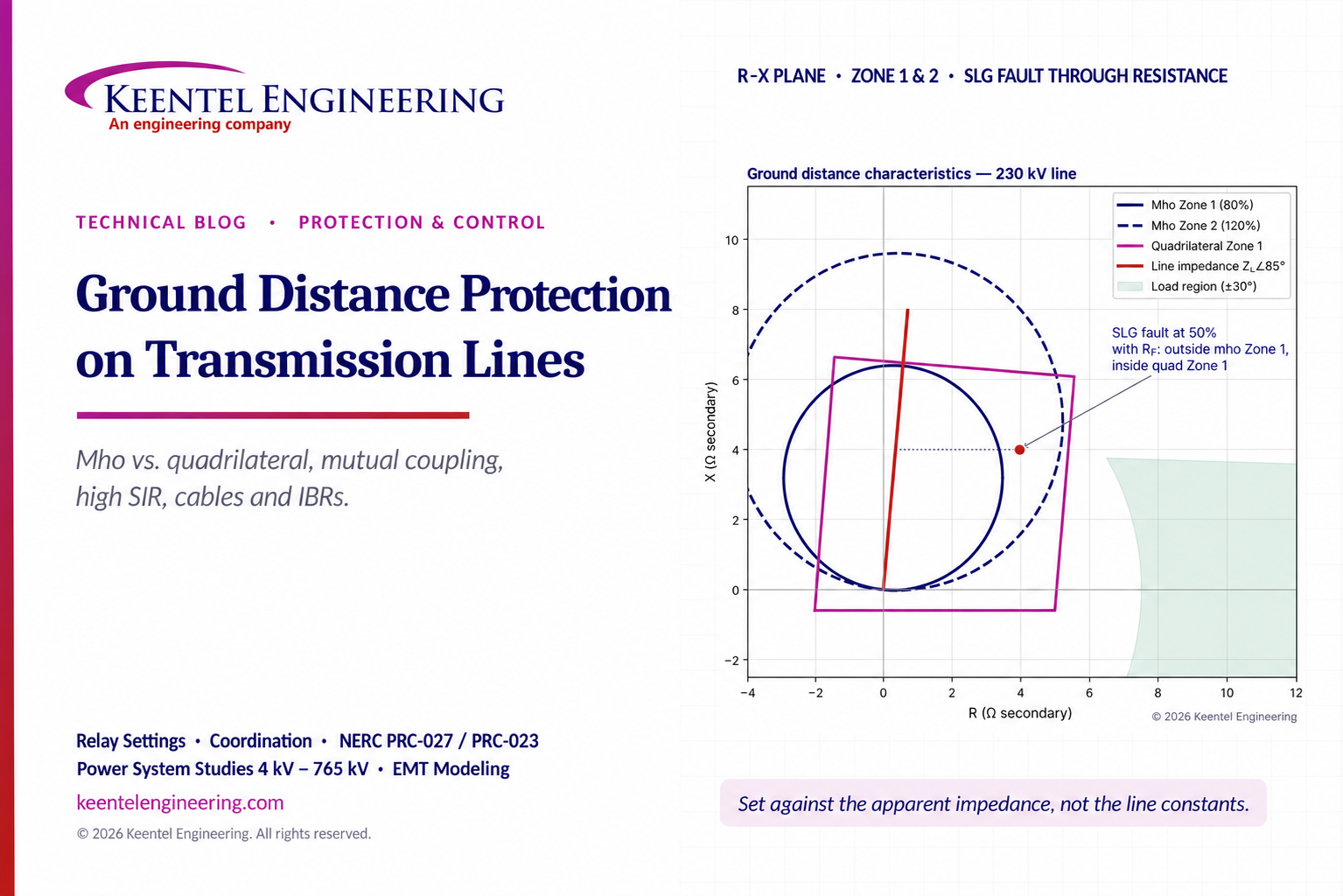
A ground distance element is only as good as the apparent impedance it is set against. Self-impedance settings fail on mutually coupled corridors, tapped ground sources, cables and three-terminal lines. Mho and quadrilateral are not rivals — they are tools. Mho is secure under heavy load and adequate for most pilot schemes; quadrilateral wins on short lines with strong sources and in step-distance backup where fault resistance coverage is the binding constraint.
Resistive reach has three ceilings: maximum load at depressed voltage, instrument-transformer angle error (roughly five times the reactive reach for an underreaching zone), and the non-homogeneity tilt. Zone 1 is the zone that misoperates. CVT transients, high SIR, mutual coupling with a grounded parallel line and tapped autotransformers all push it toward overreach.
Inverter-based resources change the rules for negative-sequence polarizing, faulted-phase selection and source-impedance assumptions — static short-circuit results alone are no longer enough.
1. Why Ground Distance Has Moved From "Optional" to "Expected"
For decades, many North American utilities protected transmission lines against ground faults with directional ground overcurrent elements and reserved distance protection for phase faults. Outside North America, ground distance was routine much earlier. The gap has closed. Every modern microprocessor line relay ships with ground mho and ground quadrilateral elements as standard functions, so enabling them is a settings decision rather than a hardware or wiring project.
That convenience is exactly the risk. A ground distance element can be switched on in minutes, but it is the most setting-sensitive function in the line relay. It depends on the zero-sequence network — the least predictable part of the power system — and it inherits every error in the line constants, the instrument transformers and the short-circuit model. Single-line-to-ground faults are by far the most frequent transmission fault type, so a ground element that overreaches or drops out is not a corner case; it is a misoperation waiting for the next lightning season.
Three structural changes make the topic urgent in 2026:
• Corridor congestion. New lines are increasingly built on shared rights-of-way and double-circuit structures, which multiplies zero-sequence mutual coupling.
• Inverter-based resources (IBRs) and large loads. Solar, wind, battery storage and data center campuses alter source strength, negative-sequence behavior and the location of zero-sequence sources on the network.
• Undergrounding and hybrid circuits. Urban and data-center feeds frequently mix overhead and cable sections, where zero-sequence impedance becomes nonlinear with fault location.
This article walks through how ground distance elements actually measure, where they go wrong, and how to set them defensibly — with worked examples throughout.
2. How a Ground Distance Element Measures Impedance
A distance relay balances an operating quantity derived from current against a restraining quantity derived from voltage. In steady state the voltage is high and the current is modest; at fault inception the voltage collapses and the current rises, and the relay decides whether the resulting impedance lies inside a defined region of the R–X plane. The reach setting is a phasor — a magnitude and an angle — and because transmission lines are highly inductive, it typically sits between 75° and 88°.
2.1 Six measuring loops, two families
A full-scheme relay evaluates six loops simultaneously. The three phase-to-phase loops use line-to-line voltage divided by the difference of the two phase currents. The three phase-to-ground loops are the subject of this article, and they need a correction: the voltage drop around a ground fault loop includes the zero-sequence (earth-return) path, so dividing phase voltage by phase current alone would over estimate distance. The relay therefore adds a scaled residual current to the phase current.
| Loop | Voltage | Compensated current | Measured impedance |
|---|---|---|---|
| A-G | V_A | I_A + k0·3I0 | V_A ÷ (I_A + k0·3I0) |
| B-G | V_B | I_B + k0·3I0 | V_B ÷ (I_B + k0·3I0) |
| C-G | V_C | I_C + k0·3I0 | V_C ÷ (I_C + k0·3I0) |
| A-B / B-C / C-A | Line-to-line | I_x − I_y | (V_x − V_y) ÷ (I_x − I_y) |
Table 1. Distance measuring loops. The phase loops need no zero-sequence compensation.
2.2 The zero-sequence compensation factor, k0
With the residual-compensation convention above, the factor that lets the relay be set entirely in positive-sequence ohms is:
k0 = (Z0L − Z1L) ÷ (3 · Z1L) = · (Z0L/Z1L − 1) ⅓ (1)
It is a complex number. On overhead lines Z0L is typically about three times Z1L with a slightly lower angle, so |k0| sits around 0.6–0.8 with a small negative angle. Relay manufacturers use different conventions (some use Z0/Z1 directly, some split into magnitude/angle or RE/RL and XE/XL), so the number entered must match the relay’s definition.
Worked example — k0 for a 230 kV line
Line constants: Z1L = 26 Ω 85° ∠, Z0L = 84 Ω 76° ∠(primary).
Z0L/Z1L = 3.23 −9° → k0 = (3.23 −9° − 1)/3 = ∠ ∠ 0.75 −13° ∠.
Entering a scalar 0.75 with the angle left at 0° shifts the compensated loop by several degrees — enough to move a resistive remote-bus fault across a Zone 1 reactance line on a short line. Always enter k0 as a complex value when the relay allows it.
3. The Mho Element: Polarization Is Everything
A mho characteristic is a circle on the R–X diagram whose diameter is the reach phasor Z_R. Internally the relay forms the operating quantity I·Z_R − V and compares its phase angle with a polarizing voltage V_pol. When the angle between them is 90° or less, the fault is inside the circle. The locus of the 90° boundary is the circle itself — a property inherited directly from the induction-cup electromechanical designs that made the mho the default shape for half a century.
3.1 Self-polarized, cross-polarized and memory-polarized
• Self-polarized (V_pol = loop voltage). The circle passes through the origin. It fails for a bolted fault immediately in front of the relay, because the loop voltage — and therefore the reference — collapses to zero.
• Cross-polarized (healthy-phase voltage). For an A-G fault the relay uses the B-C voltage rotated by 90°. This is reliable for any unbalanced fault but offers nothing for a close-in three-phase fault, where every voltage is lost.
• Memory-polarized (stored positive-sequence voltage). Modern relays memorize the pre-fault positive-sequence voltage and decay it over several cycles. This solves the zero-voltage fault and is the dominant design today.
3.2 Why memory polarization "expands" the circle
If the pre-fault voltage is used as V_pol, then for a forward fault V_pol ≈ V + I·Z_S, where Z_S is the source impedance behind the relay. Substituting into the 90° comparator yields a circle whose diameter runs from +Z_R to −Z_S. The circle still passes through the reach point, so the element does not overreach, but it swells sideways and covers more fault resistance. Three practical consequences follow:
• Weak source → large expansion → more resistive coverage. Strong source → the circle barely grows, which is why mho coverage is poor on short lines fed from stiff buses.
• The expansion is dynamic. It exists only while memory is valid and only for forward faults; steady state test-set plots show the small self-polarized circle. Dynamic state-sequence testing is needed to see the real shape.
• Reverse faults are secure. For a reverse fault the characteristic shifts into the first quadrant away from the fault impedance, which is why memory-polarized mho elements remain directional.
4. The Quadrilateral Element: Four Comparators, Four Decisions
A quadrilateral (polygonal) characteristic decouples resistive coverage from reactive reach. It is built from four straight-line comparators — each one a phase comparison between two signals derived from voltage and current — and the element asserts only when all four agree:
• Reactance line (top). Signal pair V − I·Z_R versus a polarizing current. Defines how far along the line the zone reaches.
• Directional line (bottom). I·Z_R versus memory voltage rotated 90°. Forward faults plot above it; reverse faults below.
• Right resistive blinder. V − I·R_R versus −I·Z_R. Sets fault-resistance coverage and keeps load out. ▪ Left resistive blinder. Mirrors the right blinder to bound the zone on the negative-R side.
Because the trip decision waits for the slowest of four comparators, a quadrilateral element can be marginally slower than a mho element for the same fault. In exchange the engineer controls reactive reach and resistive reach independently, and the resistive coverage is the same at every point along the line — unlike a mho circle, whose width shrinks toward the reach point.
4.1 The tilt problem
The reactance line must be polarized by a current. The voltage across fault resistance is in phase with the total fault current, which includes the remote-end contribution. The relay sees only the local contribution. When the two ends have different impedance angles — a non-homogeneous system — the local and total currents are out of phase, the fault-resistance voltage drop acquires an apparent reactive component, and the measured point tilts. Depending on the direction of load and the source angles, a resistive fault beyond the remote bus can be dragged into Zone 1 (overreach), or an internal fault can be pushed out (underreach). Relays address this with a fixed tilt (sometimes called a non homogeneity correction angle) applied to the reactance line.
4.2 Polarizing current choices
| Polarizing quantity | Strengths | Watch-outs |
|---|---|---|
| Loop (self) current | Dependable for all fault types including balanced faults; dependable during single pole-open intervals. | Affected by load flow; the tilt needed under load is hard to determine and easy to get wrong. |
| Negative-sequence current | Negative-sequence network is usually the most homogeneous, so little tilt is needed; immune to load and to zero-sequence mutual coupling. | Unreliable near inverter-based resources whose negative-sequence current is controlled, suppressed or phase-shifted by the inverter. |
| Zero-sequence current | Unaffected by load; benefits from strong zero-sequence sources such as nearby grounded-wye transformers. | Sensitive to mutual coupling and to the uncertainty of zero-sequence impedance, especially on cables. |
Table 2. Quadrilateral reactance-line polarizing options.
A useful observation: when a sequence-polarized reactance line is plotted on the loop-impedance plane, it appears to droop under forward load and lift under reverse load. This “adaptive” behavior is a feature, not an error — it is what keeps the element accurate without a load-dependent tilt.
5. Mho vs. Quadrilateral — An Engineering Comparison
| Criterion | Ground mho | Ground quadrilateral |
|---|---|---|
| Resistive coverage | Adequate for most lines; grows with weak | Independently settable; uniform along the |
| sources; shrinks near the reach point. | line; best for short lines with strong sources. | |
| Security under heavy load | Inherently secure — the circle stays away from the load region. | Requires load-encroachment logic or a conservative right blinder. |
| Coordination | Shape depends on source impedance and manufacturer polarization; harder to coordinate resistive faults. | Constant reactive reach simplifies coordination; same tilt and polarizing should be used for Zone 1 and backup Zone 2. |
| Pilot (POTT/DCB) schemes | Fault-resistance coverage comparable to quadrilateral when used as an overreaching pilot element. | Little advantage over mho in pilot use. |
| Step-distance / non pilot | Coverage can be limiting. | Clear advantage. |
| Single-pole open interval | Ground mho loops remain reliable. | Sequence-polarized elements see open-pole sequence currents; self-polarized or mho is preferred for evolving faults. |
| Underground cables | Usually the better-behaved ground distance element. | Larger under/overreach errors when k0 is uncertain. |
Table 3. Neither shape provides the resistive coverage of ground time-overcurrent or line current differential protection.
6. Application Challenges That Break Ground Distance Settings
6.1 Zero-sequence mutual coupling on parallel lines
Current in one conductor set induces voltage in any nearby conductor set. In the positive- and negative sequence networks the effect largely cancels; in the zero-sequence network it does not, because all three phase currents flow in the same direction and return through earth and shield wires. Mutual impedance Z0M on a double-circuit tower is commonly 50–70% of the line’s own Z0. Its magnitude depends on phase spacing, circuit separation, conductor and shield-wire type, earth resistivity, grounding, and the length over which the lines run together.
For an A-G fault at per-unit distance m on a coupled line, the relay measures:
Z_app = m·Z1L + m·Z0M · I0M ÷ (I_A + k0·3I0) (2)
The second term is the error. Its sign depends on the direction of zero-sequence current in the parallel circuit, I0M:
▪ Same direction(both circuits feeding a fault from the same end): the line looks longer — underreach.
▪ Opposite direction(current reversal after a breaker opens, or a parallel line fed from the other end): the line looks shorter — overreach.
▪ Parallel line out of service and grounded at both ends: the grounded circuit becomes a short circuited secondary winding; induced current flows opposite to the fault current and the line looks shorter — overreach, and the CTs on the open circuit see none of it.
The topologies that create these conditions are worth enumerating, because each one must be checked in the short-circuit model: two coupled circuits between common buses; double-circuit lines with a third parallel line; partial-length coupling that diverges to different buses; a double circuit with a switching station in one circuit; four or more lines on a shared corridor (interior circuits see the most coupling); current reversal during sequential clearing; and the grounded-for-maintenance case.
Worked example — how much does mutual coupling move the reach?
A 230 kV double-circuit line, roughly 33 miles: Z1L = 26 Ω 85°, Z0L = 84 Ω 76°, Z0M = 52 Ω 74° ∠ ∠ ∠, equal sources at both ends (Z1S = 10 Ω 86°, Z0S = 8 Ω 82°). k0 = 0.75 −13°. We solved the coupled sequence ∠ ∠ ∠ networks for a bolted A-G fault at the remote bus as seen by the relay on Circuit 1:
| Parallel circuit condition | Apparent Z, remote bus A-G fault | vs. true Z1L | Consequence for a Zone 1 set at 85% of Z1L (22.1 Ω) |
|---|---|---|---|
| In service, same-direction I0 | 31.4 Ω 84° ∠ | +21% | Secure, but a 125% Zone 2 (32.5 Ω) has only ~3% margin for a bolted fault and none for a resistive one. |
| Out of service, ungrounded | 26.0 Ω 85° ∠ | 0% | Correct measurement — the textbook case. |
| Out of service, grounded both ends | 21.4 Ω 87° ∠ | −18% | Zone 1 overreaches the remote bus. A fault on the next line section can trip instantaneously. |
Table 4. Keentel worked example — values computed from a coupled sequence-network solution. Illustrative system, not a specific utility circuit.
Setting strategy for coupled lines
1. Set against apparent impedance, not self impedance. Run remote-bus SLG faults for every credible configuration: both circuits in service, parallel circuit open, parallel circuit open and grounded, and the reversal produced by sequential clearing.
2. Underreaching Zone 1: 80–85% of the lowest apparent impedance found. In the example, ~0.82 × 21.4 Ω ≈ 17.5 Ω, not 22.1 Ω.
3. Overreaching zones: base them on the highest apparent impedance (31.4 Ω here), then confirm coordination with adjacent Zone 1 elements.
4. Second compensation factor. Some relays accept a mutual compensation factor, k0M = Z0M/(3·Z1L) (0.67 −11° in the example), applied using the parallel circuit’s residual current wired ∠ into the relay. It restores accurate measurement when that current is visible — but not for the grounded-out case, where the parallel line’s breaker CTs carry no current. Follow the manufacturer’s guidance on which zones may use it; it is normally restricted to overreaching zones to avoid Zone 1 overreach when the parallel line opens.
5. Directional element polarizing. Zero-sequence voltage and current are both corrupted by coupling. Negative-sequence directional polarizing is generally preferred on strongly coupled corridors.
6. Adaptive logic. Use the parallel breaker status to switch setting groups when the companion circuit is opened, and check pilot transient-blocking timers against current reversal.
6.2 Weak zero-sequence sources and low residual current
Ground distance elements are supervised by a residual-current fault detector. If a terminal has little zero-sequence source behind it, a remote-end fault may produce only a few tens of amperes of 3I0 — below the detector’s minimum pickup once the CT ratio has been chosen to carry maximum load. Consider a 69 kV line coupled to a 138 kV circuit on the same corridor: with a 600:5 CT and a 0.5 A secondary detector minimum, the element cannot see less than 60 A primary, yet a remote fault with the strongest local source out may deliver half that. The options, in rough order of preference, are:
• Use the pilot channel. A sensitive forward ground directional overcurrent element keyed into POTT can be set lower than the distance fault detector — but its pickup must still coordinate with the remote reverse-blocking element.
• Weak-infeed echo logic. The weak terminal echoes the strong terminal’s permissive signal and converts it to a trip when it measures elevated zero-sequence voltage or depressed phase voltage. Verify thresholds carefully: very low V0 sits at the bottom of the setting range.
• Sequential tripping. Allow the strong end to clear first; the weak end then sees enough current to operate. Acceptable where the fault current magnitude is low and stability margins permit the delay.
▪ A timed Zone 2 quadrilateral, where the relay provides independent mho and quadrilateral outputs, to trip ahead of the ground time-overcurrent backup (commonly coordinated near one second).
Coupled lines with POTT schemes on both circuits add another trap: when the two ends of the faulted circuit open at different times, current in the healthy circuit reverses. If keying, blocking and echo timers are not coordinated, the healthy line trips.
6.3 Capacitive voltage transformer (CVT) transients
CVTs are standard at 115 kV and above because they are economical, support power-line carrier coupling and improve breaker transient recovery voltage. Their stacked capacitors, tuning reactor and step-down transformer store energy. When a fault collapses the primary voltage, that energy rings down through the secondary for roughly one to two cycles. During that interval the filtered fundamental voltage sags below the true value, so the measured impedance is too small — the classic cause of Zone 1 transient overreach.
Six design and system factors control the severity:
• Point on wave. A fault at voltage zero is worst, because the capacitors hold maximum energy. ▪ Stack capacitance. Higher-capacitance CVTs reproduce the primary voltage more faithfully.
• Ferroresonance suppression circuit. Active (tuned L-C) suppressors behave like a band-pass filter and add delay; passive (resistive) suppressors produce markedly less distortion.
• Burden. Inductive, low-power-factor burdens make the response worse and oscillatory below nominal frequency.
▪ Step-down transformer excitation.
• Source impedance ratio (SIR). The higher the SIR, the smaller the steady-state fault voltage and the larger the relative error.
Mitigation options include reducing or delaying Zone 1 on high-SIR terminals; specifying high capacitance CVTs with passive suppression on new projects; and enabling the relay’s CVT-transient detection logic, which adds delay only when transient conditions are detected and the fault is not close in. As a broad rule, CVTs with active suppression permit full Zone 1 reach at low SIR (around 4 or below), tend to require a reduced or delayed Zone 1 at intermediate SIR, and are commonly accompanied by a disabled Zone 1 near an SIR of 20; passive-suppression designs tolerate considerably higher SIR. Terminals at IBR plants often behave as weak sources and benefit from transient-blocking logic.
6.4 CT saturation
A saturating CT delivers a current that is smaller and phase-advanced relative to the primary current. After the relay’s cosine or Fourier filter, the current phasor magnitude dips and its angle shifts for several cycles, so the element underreaches temporarily. For distance protection this is a dependability problem, not a security problem: tripping is slowed, but it is not falsely initiated. Zone 1 usually asserts before saturation develops. The vulnerable element is a time-delayed Zone 2, whose timer can reset when the impedance briefly leaves the characteristic.
A practical sizing screen for an overreaching pilot or Zone 2 element, derived from published relay performance research, is:
Z_burden ≤ 6 · V_k ÷ [ (X/R + 1) · I_sf ] (3)
where V_k is the CT’s C-class voltage rating, I_sf the maximum secondary fault current and X/R that of the fault-current contribution. Example: a C800 CT at 1200:5 carrying 25 kA (104 A secondary) with X/R = 15 permits up to 2.9 Ω of total secondary burden. If the burden is lower, reach and operating time are preserved.
Where that test fails, two approaches are used: (1) a modest increase in Zone 2 reach — but not as compensation for saturation-driven magnitude errors much larger than about 30%, because the extra reach can overlap remote Zone 1 elements; and (2) a dropout-extension timer on the Zone 2 pickup, so the coordination timer keeps running through brief saturation dropouts.
6.5 Transformer inrush
Inrush is mainly a concern for phase loops. Inrush rarely produces enough genuine zero-sequence current to operate a ground distance element; the risk is unequal CT saturation creating false residual current. Where a line terminates directly into a transformer, repeat the CT sizing check with inrush current in place of fault current — although maximum fault current usually governs.
6.6 Faulted-phase selection
A close-in A-G fault depresses more than one loop impedance. The A-B or C-A loop can land inside Zone 1 even though only phase A is faulted. Without reliable phase selection the relay trips three-pole or blocks single-pole tripping. Phase selection is not a user setting — it is part of the relay design — but the engineer must understand its limitations:
| Method | Principle | Where it struggles |
|---|---|---|
| Current magnitude | Faulted loops carry more current. | Weak infeed; residual current not caused by the fault (e.g., CT saturation). |
| Voltage magnitude | Faulted loops lose voltage. | Strong sources and low SIR, where voltages barely drop. |
| Incremental current | Compare fault-induced changes between phases. | Weak infeed. |
| Incremental voltage | Compare fault-induced voltage changes. | Switch-onto-fault; unrelated transients. |
| Impedance | Lowest loop impedance indicates the fault type. | “Ghost” impedances in healthy loops. |
| Symmetrical components | Angle relationship between I0, I2 and I1. | Sequence quantities not caused by the fault — and IBRs with controlled I2. |
| Jump detection | Coincident step changes in current and voltage. | Non-fault transients. |
Table 5. Faulted-phase selection principles. Modern relays run several in parallel.
Where the relay’s design allows it, a conventional mitigation is to tighten the phase-to-phase resistive reach of Zone 1 near strong ground sources so the healthy phase-to-phase loop cannot fall inside the zone for a close-in single-phase fault. Near IBR plants, voltage-based phase selection improves both security and dependability.
6.7 High source impedance ratio (SIR)
SIR is the ratio of the source impedance behind the relay to the protected-line impedance. It can be calculated directly from the relay voltage for a remote-bus fault: phase-to-ground voltage for a ground fault gives the ground SIR; phase-to-phase voltage gives the phase SIR. A short-circuit program provides both. For a homogeneous system the per-unit relay voltage for a remote fault is simply 1/(1 + SIR):
| SIR | 0.5 | 1 | 4 | 10 | 20 | 30 |
|---|---|---|---|---|---|---|
| Relay voltage, % of nominal | 66.7% | 50.0% | 20.0% | 9.1% | 4.8% | 3.2% |
| Secondary volts (66.4 V L-N nominal) | 44.3 | 33.2 | 13.3 | 6.0 | 3.2 | 2.1 |
Table 6. At SIR 20 the relay must judge reach from about 3 V secondary — where VT ratio error, angle error and CVT transients dominate.
Two points are often missed. First, SIR is contingency-dependent: a 69 kV line with an SIR of about 1 in normal configuration can exceed 50 when a nearby source transformer is out. Second, with wire-wound VTs the error is almost entirely steady-state, so the physical length of the line matters more than its
electrical length — a short line magnifies every percent of measurement, model and line-constant error. Use the VT accuracy class to pull back underreaching zones on high-SIR terminals, and remember that a wye-connected VT angle error is amplified in phase-to-phase measurement.
Arc voltage is proportionally larger on high-SIR lines and can push the measured point either way depending on its phase shift. When the compromise between coverage and security becomes untenable, the answer is a communications-assisted scheme — line current differential, phase comparison, POTT or DCB — at which point an instantaneous underreaching Zone 1 may not be needed at all.
6.8 Underground cables and hybrid circuits
Cable faults are slower and costlier to repair than overhead faults — often three to five times longer — and an uncleared arc in a pipe-type cable can burn through the steel pipe. Most cable faults involve ground. Yet ground distance is at its weakest on cables:
▪ Series inductance is 30–50% lower than an equivalent overhead line, and shunt capacitance can be 30–40 times higher.
• Zero-sequence impedance depends on the return path: sheath only, earth only, sheath and earth in parallel, or adjacent cable sheaths, pipes and rails. The path changes with fault location, bonding method, backfill resistivity and neighboring metallic services.
▪ Cable Z0 has a much lower angle than overhead Z0, so k0 can be large with a strongly negative angle.
• k0 is not constant along the cable. For solidly bonded and cross-bonded cables the compensated loop impedance is a nonlinear function of distance; with cross-bonding it even jumps at each minor-section boundary because the return path changes.
▪ Pipe-type cables are worse still: the steel pipe’s permeability varies with ground-fault current, so Z0 itself changes with fault magnitude.
Symmetrical components assume balanced impedances — an assumption that sheath bonding and transpositions violate. Credible cable fault studies therefore use a phase-domain model(EMTP-type programs or equivalent matrix tools) retaining sheaths, cross-bonding, ground-continuity conductors and core-to-sheath fault paths.
The setting logic that follows from this: choose the Zone 1 compensation factor for the return path that produces no overreach (typically sheath return), and the overreaching-zone factor for the path that produces no underreach (typically earth return), using the remote-terminal fault with the parallel cable out for Zone 1 and in service for the overreaching zones. Get it wrong and the error is not a few percent: a k0 chosen for one return path can make the element measure a remote-end fault at a fraction of — or several times — its true distance. Among ground distance elements, ground mho has tended to show the smallest errors. In practice, line current differential is the preferred primary protection for transmission cables, with negative-sequence directional comparison as an alternative, and ground distance retained as backup.
6.9 Single-pole tripping and the open-pole interval
Most overhead-line faults are temporary single-phase flashovers. Single-pole tripping (SPT) and reclosing clears the faulted phase while the other two continue to transfer power, which reduces the risk of power swings and allows reclosing without a synchronism check. Distance protection carries three extra burdens in SPT schemes:
1. Select the right phase. A wrong selection produces either an incorrect single-pole trip or an unnecessary three-pole trip.
2. Stay stable during the dead time. The open phase generates zero- and negative-sequence current with no fault present. On long, heavily loaded lines, healthy-phase ground loops can drift into a zone. The relay must detect the open-pole state — from its own trip command, breaker auxiliary contacts, and/or current and voltage — and block the affected loops.
3. Still catch an evolving fault. A second phase faulting during the dead time must be detected and selected correctly.
The parallel line is also affected. During the open-pole interval the faulted phase’s load transfers to the healthy circuit, which then carries unbalance current. Sensitive long-reach ground elements on that circuit should be time-delayed beyond the reclosing dead time — a backup delay of at least about 1.5 seconds is typical where open-pole intervals approach that length. Ground mho loops tend to remain reliable during the open-pole interval; sequence-polarized quadrilateral elements need more care.
6.10 Series-compensated lines
Series capacitors increase transfer capacity without new lines but introduce voltage inversion, current inversion, sub-synchronous oscillation, capacitor unbalance during single-pole tripping, phase segregated bypass by the capacitor protection, and current distortion. These effects reach beyond the compensated line into adjacent lines — sometimes two buses away. Every line relay inside that zone of influence must be series-compensation capable and must be re-set. Settings depend on capacitor size and location (mid-line versus line-end) and on whether the VT is on the line or bus side of a line-end bank. Good practice is to validate the settings with closed-loop hardware-in-the-loop testing on a real time simulator before energization, and to revisit them whenever further compensation or network changes are added.
6.11 In-line autotransformers and tapped ground sources
Where a line relay’s CTs and VTs sit on opposite sides of an in-line autotransformer, the relay sees an impedance that includes the transformer, a fault on one side may look like a close-in fault on the other, and transformer faults may appear forward or reverse depending on which side the CTs are on. If the relay is configured to work in the voltage base of the VT side, the effective CT ratio must be scaled by the transformer ratio. For example, 1200:5 CTs on the 115 kV side feeding a relay whose VTs are on the 138 kV side give an effective ratio of 240 × 115/138 = 200:1. Looking through an autotransformer also changes the overall impedance angle, so the characteristic angle must be revisited; the transformer’s test-report impedance is usually more accurate than the line constants and can justify tighter margins.
A transformer tapped from the line with a grounded-wye winding and a delta winding (two-winding, three-winding, or an autotransformer with a delta tertiary) is a zero-sequence source in the middle of
the protected zone. It pulls residual current away from the line terminals, so remote ground faults appear farther away (Zone 2 underreach). Zone 2 must be set on the largest apparent impedance with the tap in service; Zone 1 must not be based on the tap-out condition alone. When the tapped bank is large and close to one terminal, the opposite effect appears: with the remote breaker open, a ground fault on the transformer low side can measure inside Zone 1 of the near terminal — a reach-through misoperation. Study both remote-open and remote-closed cases, consider a neutral reactor on a grounded-wye primary (not effective for autotransformers), and add blocking for low-side faults in overreaching pilot zones where needed.
6.12 Three-terminal lines
Three-terminal lines typically have a short leg and a long leg. Infeed from the third terminal makes faults look farther away; outfeed (current flowing out at a tap) can make them look closer. Set Zone 1 with outfeed in mind, and set overreaching Zone 2 at every terminal to at least about 125% of the largest apparent impedance to the most distant terminal, including infeed.
7. A Defensible Setting Method
7.1 Reactive reach
| Zone / scheme | Typical criterion | Key check |
|---|---|---|
| Zone 1 (underreaching, instantaneous) | 80–85% of the lowest apparent impedance for a remote-bus SLG fault across all credible configurations. | Also test SLG faults on the parallel circuit (in service and grounded); if any produce a lower apparent impedance, base the 80– 85% on that value. Reduce further for high SIR, CVT class and VT accuracy. |
| Zone 2 (step-distance backup) | At least ~120% of the line’s highest apparent impedance; around 150% is desirable where coordination allows. 125% is a common two-terminal figure. | Must not overlap adjacent-line Zone 1 for bolted and resistive faults; watch a short line following a long line. |
| Zone 2 (pilot overreaching, POTT) | Sensitive — often around 200% of line impedance. | Must never underreach the remote bus under any coupling or infeed condition. |
| Zone 3 (reverse, pilot blocking) | Set to overreach the remote terminal’s forward pilot zone; a common practice is reverse reach equal to the remote forward reach, using the line impedance as margin. | Verify with resistive as well as bolted faults — subtracting the line impedance works for bolted faults but not always for resistive ones. |
| Three-terminal lines | Zone 1 accounting for outfeed; Zone 2 ≥ ~125% of the longest leg’s apparent impedance including infeed. | Check from all three terminals. |
Table 7. Reactive reach guidance for ground distance zones.
7.2 Resistive reach of quadrilateral elements — three ceilings
Ceiling 1: load
For a self-polarized quadrilateral element, the right resistive blinder must stay clear of the minimum load impedance, evaluated at the lowest credible operating voltage (typically 0.85 per unit). Where the minimum load impedance exceeds the maximum fault resistance to be covered, a sound setting lies roughly midway between the two, while keeping at least a 20% margin below the load impedance.
Example: a 230 kV line with an 800 MVA emergency rating has a minimum load impedance of (0.85 × 230 kV)² ÷ 800 MVA ≈ 47.8 Ω primary. With 20% margin the blinder may not exceed about 38 Ω. If the target fault resistance (arc plus tower footing or vegetation contact) is 10 Ω, a setting in the mid-20s of ohms balances coverage and security.
On very long, heavily loaded lines the load impedance can fall below the arc resistance to be covered. Then a compromise is unavoidable: supervise the ground element with an adjustable residual-current threshold, use the relay’s load-encroachment logic, or limit the resistive reach to about 80% of the minimum load impedance.
Ceiling 2: instrument transformer angle error
A small angle error rotates the measured impedance. With a long resistive reach, that rotation lifts a resistive remote-bus fault over the reactance line. Treating the remote fault point as the vertex of a thin right triangle, the largest secure resistive reach for an underreaching zone is approximately:
R_MAX ≈ (Z_L − Z_R) ÷ sin ε (4)
where Z_L is the line impedance, Z_R the reactive reach and ε the total angle error. Typical contributions are about 0.8° for the CT, 2° for the VT and 0.2° for the relay — a cumulative ~3°.
| Total angle error ε | 1° | 2° | 3° | 4° |
|---|---|---|---|---|
| R_MAX (Ω sec), Z_L = 6.0 Ω, Z_R = 4.8 Ω | 68.8 | 34.4 | 22.9 | 17.2 |
| R_MAX as a multiple of Z_R | 14.3× | 7.2× | 4.8× | 3.6× |
Table 8. This is why an underreaching ground quadrilateral’s resistive reach is usually held below about five times its reactive reach.
Ceiling 3: non-homogeneity tilt
Where source and line angles differ, calculate the angle between the current at the fault and the current at the relay for the chosen polarizing quantity, and apply that as a fixed tilt to the reactance line. For negative-sequence polarizing:
T2 = arg[ (Z1S + Z1L + Z1R) ÷ ((1 − m)·Z1L + Z1R) ] (5)
Example: a stiff local source (Z1S = 3 Ω 87°), a short line (Z1L = 5 Ω 84°) and a weaker remote source ∠ ∠ with a low angle (Z1R = 12 Ω 65°) give T2 ≈ 4.8° at mid-line, 6.6° at the Zone 1 reach point (m = 0.8) and ∠ 8.0° at the remote bus. Sequence-polarized tilts need no load correction because load flows only in the positive-sequence network; a self-polarized tilt does, and that correction is not trivial. Where the remote source is an inverter-based plant, its negative-sequence current angle is set by control software rather than by an impedance, and equation (5) no longer describes it — see Section 8.
Estimating the fault resistance to cover
Three classic empirical expressions estimate arc resistance from arc length L (meters) and current I (amperes):
| Method | Expression | 3 kA, 12 m arc | 1 kA, 12 m arc |
|---|---|---|---|
| Warrington (1931) | R = 28,710 · L ÷ I^1.4 | 4.7 Ω | 21.7 Ω |
| Blackburn | R = 1,444 · L ÷ I | 5.8 Ω | 17.3 Ω |
| Terzija–Koglin | R = (855.3/I + 4,501.6/I²) · L | 3.4 Ω | 10.3 Ω |
Table 9. The arc length should include stretching by wind and magnetic forces — a conservative allowance is about 33 m per second of clearing time. A 0.3 s Zone 2 delay therefore adds roughly 10 m to a ~2 m flashover path.
These values apply where an overhead shield wire paralleling the tower footings keeps the effective ground resistance low. Without a shield wire, tower footing resistance adds directly — commonly 5 to 20 Ω, and 100 Ω or more in rocky or high-resistivity soil. Tree contacts and high-resistivity terrain are the strongest arguments for quadrilateral elements or sensitive ground directional overcurrent backup.
7.3 Coordinating resistive reach
Bolted-fault coordination is routinely verified; resistive-fault coordination often is not. Three rules prevent most surprises:
▪ Same tilt for backup Zone 2 and the adjacent line’s Zone 1, so the reactance lines are parallel and cannot cross inside the characteristic.
▪ Same polarizing quantity for zones that must coordinate.
• Know the manufacturer’s resistive convention. Some relays measure fault resistance directly in the loop; others scale it by (1 + k0). Two relays with the "same" setting can have very different coverage.
Mho coordination has its own trap: different polarization schemes expand differently, and a short line following a long line is the classic mis-coordination geometry. Apply resistive faults in the short-circuit program at the adjacent line’s Zone 1 reach point and confirm the backup timer margin holds.
8. Inverter-Based Resources: What Changes for Ground Distance
Synchronous machines behave like voltage sources behind a fixed impedance. Inverters behave like controlled current sources: their fault current is limited to roughly 1.0–1.5 per unit, its angle is set by control priorities, and the negative-sequence component may be suppressed, absent or deliberately injected depending on the grid code the plant follows. For ground distance protection that means:
▪ Ground faults remain measurable at the plant terminal because the main power transformer’s grounded-wye winding provides a stiff zero-sequence source — but positive- and negative sequence contributions are small and non-traditional.
▪ Negative-sequence-polarized quadrilaterals and directional elements can misbehave at, and near, IBR terminals.
▪ Phase selection based on sequence-current angles can pick the wrong loop; voltage-based selection is more robust.
▪ High apparent SIR at the IBR terminal brings CVT-transient and steady-state accuracy concerns into play; CVT transient-blocking logic is often warranted.
▪ Static tilt calculations break down, because the remote “source impedance” in equation (5) is not an impedance.
The practical response is to lean on schemes that do not depend on IBR sequence behavior — line current differential, zero-sequence-based directional comparison, and voltage-based phase selection — and to validate settings with the plant’s vendor-specific EMT models rather than with generic short circuit equivalents alone.
9. Where Ground Distance Meets NERC Compliance
Ground distance settings sit inside several NERC Protection and Control (PRC) obligations for registered Transmission Owners, Generator Owners and Distribution Providers:
| Standard | Relevance to ground distance |
|---|---|
| PRC-027-1 — Coordination of Protection Systems for Performance During Faults | Requires a documented process for developing settings that coordinate, and periodic re-validation of fault current levels against the values used. Mutual-coupling and tapped-source cases belong in that process. |
| PRC-004-6 — Protection System Misoperation Identification and Correction | An overreaching ground Zone 1 or a dropped-out Zone 2 is a reportable misoperation with a corrective action plan. Root-cause work often lands on k0, mutual coupling or CVT transients. |
| PRC-023-6 — Transmission Relay Loadability | Applies to phase protective relays. Ground elements are generally outside its scope — but a self-polarized ground quadrilateral can still be load limited, so the engineering check remains necessary. |
| PRC-026 — Relay Performance During Stable Power Swings | Focuses on load-responsive protective relays; the open-pole and swing behavior of long-reach ground zones should still be reviewed alongside it. |
| PRC-028-1, PRC-029-1, PRC-030-1 — IBR disturbance monitoring, ride through and unexpected IBR event mitigation | Line protection at and near IBR plants must not cause ride-through failures; disturbance records required by these standards are the best evidence for tuning IBR-adjacent ground elements. |
Table 10. Confirm current versions and effective dates on the NERC standards page before relying on them; applicability depends on registration.
10. Quick-Reference Application Guide
| Application | Ground mho | Ground quadrilateral |
|---|---|---|
| Mutually coupled parallel lines | Can over- or underreach — set on apparent impedance. | Same; zero-sequence polarizing also affected. |
| Short line, weak source, high SIR | Coverage limited by accuracy; reduce Zone 1 reach. | Better resistive coverage on strong source short lines; respect the R_MAX limit. |
| CVT transients | Enable CVT transient logic where SIR is high. | Same. |
| CT saturation / inrush | Dropout-extension timer for Zone 2; check false 3I0 on inrush. | Same. |
| Faulted-phase selection | Multi-criteria selection; follow manufacturer guidance. | Same. |
| Underground cables | Usually the better ground distance choice — as backup. | Less robust to k0 uncertainty; prefer differential. |
| Single-pole open interval | Ground mho loops reliable. | Use self-polarized quad or mho for evolving faults. |
| Series compensation | Tune with hardware-in-the-loop testing. | Same. |
| In-line/tapped transformers, multi-terminal | Account for infeed (Zone 2) and outfeed (Zone 1). | Same. |
| Long, heavily loaded lines | Adequate coverage, inherently load secure — often the simpler choice. | Needs load encroachment or residual supervision. |
| Step-distance Zone 2 | >120% of line; coordinate reactive and resistive reach. | >120% of line; same tilt and polarizing as adjacent Zone 1. |
| Pilot schemes | Zone 2 ~200%; reverse Zone 3 ≥ remote Zone 2. | Same. |
Table 11. Summary guide (Keentel synthesis).
11. How Keentel Engineering Supports Ground Distance Protection
Ground distance problems rarely sit within a single discipline. They involve line constants, short-circuit models, instrument-transformer specifications, relay logic, and compliance evidence. Keentel’s service lines map directly onto that chain:
| Keentel service line | What we deliver for ground distance protection |
|---|---|
| Protection & Control Engineering | Line protection philosophy and scheme selection (step-distance, POTT, DCB, line current differential, SPT); complete relay setting calculations for ground mho and quadrilateral elements; k0 and mutual compensation; resistive reach, tilt and load checks; coordination with adjacent lines; settings review of existing fleets; witnessing and commissioning support (acceptance and maintenance testing is performed by accredited testing contractors). |
| EHV/HV/MV Power System Studies | Short-circuit model building and validation with mutual impedances, tapped ground sources and contingencies; apparent-impedance and SIR studies for every terminal; resistive-fault coordination sweeps; EMT studies for CVT transients, series capacitors, cables and IBR behavior. |
| Transmission Line Design | Line-constant and mutual-impedance calculations from tower geometry, conductor and shield-wire data; shield-wire and grounding design to control tower-footing resistance; reconductor and double-circuit conversions with |
| protection impacts identified at design stage. | |
| Substation Design | CT and CVT specification (accuracy class, C-rating, stack capacitance, ferroresonance suppression type), burden calculations, and relay panel design. |
| NERC O&P Compliance(PRC) | PRC-027 coordination processes and periodic fault-current reviews; PRC-004 misoperation root-cause analysis and corrective action plans; PRC-023 loadability documentation. |
| POI Interconnection & Utility Scale Renewables | Protection requirements at IBR points of interconnection; settings validated against vendor EMT models; PRC-028/029/030 coordination. |
| Data Center Power Engineering | Protection of hybrid overhead-cable feeds and tapped large-load substations, including zero-sequence source impacts on existing utility line relays. |
| Owner’s Engineer Services | Independent review of EPC and utility protection settings, relay settings files and test reports before energization. |
Table 12. Keentel service lines relevant to transmission line ground protection.
12. Three Anonymized Case Studies
These case studies are anonymized, illustrative engineering scenarios that combine conditions commonly found on North American transmission systems. Owner names, locations and identifying details are withheld or changed, and numerical values are representative — calculated from simplified models to show the mechanisms described above.
Case Study 1 — The Maintenance Outage That Turned Zone 1 Into Zone 2
230 kV double-circuit corridor · mutual coupling · grounded parallel line
Situation
A transmission owner operated two 230 kV circuits on shared double-circuit structures for about 33 miles. Ground distance Zone 1 on both circuits had been set at 85% of the positive-sequence line impedance (22.1 Ω primary on a 26 Ω line) with a standard k0 calculated from line constants. During a planned outage, one circuit was opened and grounded at both ends for line work. A single-line-to ground fault just beyond the remote bus on an adjacent line tripped the in-service circuit instantaneously from Zone 1 — an overtrip that removed the only remaining path on the corridor.
Engineering review
The coupled zero-sequence network was rebuilt with the corridor’s mutual impedance (Z0M ≈ 52 Ω 74°), which had been missing from the planning-grade short-circuit case used for the original ∠ settings. Remote-bus SLG faults were then run for each configuration. With the parallel circuit grounded, the in-service relay measured 21.4 Ω — about 18% short of the true line impedance and inside its 22.1 Ω
Zone 1. The mutual compensation input could not help: the parallel circuit’s breaker CTs were open, so the induced current flowed through the grounding equipment and was invisible to the relay.
The same study revealed the opposite exposure. With both circuits in service, a remote-bus fault measured 31.4 Ω, leaving the 125% Zone 2 (32.5 Ω) only about 3% of margin for a bolted fault — and no margin for a resistive one. Corrective settings
• Zone 1 re-based on the lowest apparent impedance: ≈ 82% × 21.4 Ω ≈ 17.5 Ω.
• Zone 2 re-based on the highest apparent impedance (31.4 Ω), extended to ~38 Ω after checking resistive-fault coordination against adjacent Zone 1 elements.
• Ground directional element moved from zero-sequence to negative-sequence voltage polarizing.
• An alternate setting group, selected by the parallel breaker’s status, for operating configurations where the companion circuit is open.
• Pilot transient-blocking timers re-checked against current reversal during sequential clearing.
Lesson
On a coupled corridor, the protected line has no single impedance. It has a range, and Zone 1 must sit under the bottom of that range while overreaching zones clear the top.
Case Study 2 — A Short Line to a Solar-Plus-Storage Plant _138 kV interconnection · high SIR · CVT transients · IBR negative-sequence behavior _
Situation
A 138 kV generator interconnection line of a few miles connected a utility switching station to a hybrid solar-and-battery plant. Both terminals used CVTs with active ferroresonance suppression. The initial design applied identical settings at both ends: ground quadrilateral Zone 1 at 80% of the line with negative-sequence polarized reactance lines, and a long resistive reach chosen for tree-contact coverage.
Engineering review
At the utility terminal the ground SIR was modest, but the plant terminal sees the line through its own inverters and main power transformer. For phase quantities the inverters contribute only limited, controlled current, so the effective positive- and negative-sequence source behind the plant relay is weak and the phase SIR exceeded 20. The transformer’s grounded-wye winding still provides a strong zero-sequence source.
Three exposures were identified: (1) CVT transient overreach of Zone 1 at the high-SIR plant terminal; (2) unreliable negative-sequence polarizing and phase selection at the plant terminal, because the inverters’ negative-sequence current followed control logic rather than network impedance; and (3) a resistive reach at the utility end that exceeded the angle-error limit for an underreaching zone on such a short line.
A conventional tilt calculation at the utility terminal gave a few degrees of correction. That calculation assumes the remote source is an impedance; with an inverter at the remote end it is not, so the result was used only as a starting point and validated against the plant vendor’s EMT model.
Corrective settings
• Primary protection changed to line current differential over the new fiber path, with POTT as a second high-speed scheme.
• At the plant terminal: Zone 1 disabled; zero-sequence-polarized quadrilateral and ground directional overcurrent used for the pilot overreaching function; weak-infeed echo logic enabled and tested.
• At the utility terminal: Zone 1 resistive reach reduced to below about five times the reactive reach; CVT transient-detection logic enabled.
• Voltage-based faulted-phase selection enabled where the relay offered it.
• Settings verified with EMT simulation of the inverter models for internal and external faults, including resistive faults.
Lesson
An IBR terminal can be weak for phase faults and strong for ground faults at the same time. Settings that assume a conventional machine behind the relay fail in both directions.
Case Study 3 — A Hybrid Overhead–Cable Feed With a Tapped Ground Source
138 kV overhead + underground cable · large-load tap · k0 uncertainty · reach-through
Situation
An existing 138 kV overhead line was extended underground for its final segment to reach a new large load campus substation. Separately, an industrial customer substation with a grounded-wye/delta transformer had been tapped from the overhead section close to the utility terminal. The original step distance ground settings assumed a homogeneous overhead line.
Engineering review
Cable section. The cable’s zero-sequence impedance varied by a factor of more than two depending on whether fault current returned through the sheaths, the earth or both, and its angle was far lower than the overhead section’s. With a single k0, the ground element’s measured distance to a fault at the cable
end swung from significant overreach to severe underreach depending on the return path. A phase domain model including the sheath bonding arrangement was required to quantify the error.
Tapped ground source. With the tap in service, remote ground faults measured noticeably farther away, eroding Zone 2 dependability. With the far-end breaker open, a ground fault on the tap transformer’s low side measured inside Zone 1 of the near terminal — a latent reach-through misoperation.
Corrective settings
• Ground distance retained as backup only: Zone 1 limited to the overhead portion short of the tap’s reach-through point; overreaching zones set with a k0 for the earth-return path and confirmed against the largest apparent impedance with the tap in service.
• Overreaching pilot ground zone blocked for tap low-side faults.
• Field measurement of the cable’s zero-sequence impedance specified as a commissioning requirement, with settings re-checked against the measured values.
Lesson
Adding a cable or a tap is a protection change, not just a construction change. Every relay that sees the new zero-sequence path needs its settings rebuilt.