A Coordinated Electric System Interconnection Review—the utility’s deep-dive on technical and cost impacts of your project.
Challenge: Frequent false tripping using conventional electromechanical relays
Solution: SEL-487E integration with multi-terminal differential protection and dynamic inrush restraint
Result: 90% reduction in false trips, saving over $250,000 in downtime
The three operating regions you have to design to
| Device | Output vs voltage | Response | Best suited to | Main limitations |
|---|---|---|---|---|
| Mechanically switched capacitor or reactor | Proportional to voltage squared | Seconds; discrete steps; limited switching operations per day | Steady-state reactive supply, voltage profile, loss reduction | No dynamic capability; step voltage change on switching; capability collapses when most needed |
| Static var compensator | Capacitive branches proportional to voltage squared | A few cycles; continuously controllable | Continuous control where cost matters and deep voltage support is not the driver | Square-law capability loss; harmonic filters are part of the plant and interact with the network |
| STATCOM | Approximately proportional to voltage — constant current capability | One to two cycles closed loop; converter response faster still | Voltage stability margin, weak interconnections, fast disturbance recovery, flicker and unbalance compensation | Higher capital cost; converter losses; adds a converter and its control dynamics to the network |
| Synchronous condenser | Governed by machine capability and excitation | Excitation response in the hundreds of milliseconds; inherent inertial response instantaneous | System strength and inertia, short-circuit contribution, black start support | Rotating plant with maintenance and losses; slower controlled response than a converter |
| STATCOM with energy storage | Reactive as a STATCOM, plus real power within the storage rating | As STATCOM for reactive; real power limited by storage | Where a real power deficiency is part of the problem | Cost and complexity of the storage; different failure and maintenance profile |
| Stage | Keentel scope | Outcome |
|---|---|---|
| Screening | Series-compensation proximity, radial contingency review, UIF and short-circuit ratio screening, frequency scans | Early identification of which SSO types apply |
| Detailed studies | PSCAD/EMTDC EMT studies with vendor real-code models, impedance-based and frequency-scan analysis | Clear evidence of stability margins or risk |
| Model quality | EMT model review, benchmarking against positive-sequence models, model acceptance support | Models that system operators accept |
| Mitigation | Control retuning recommendations with vendors, SSDC and bypass logic requirements, protection and monitoring specifications | Practical, coordinated solutions |
| Interconnection support | SSR and SSO study reports for ISO and utility requirements, response to reviewer comments | Fewer delays in the interconnection process |
Resilience: designing CDUs to the facility Tier objective
Liquid cooling makes heat removal more critical, not less. Cold plates hold only seconds of thermal buffer. If TCS flow stops, processors throttle or shut down very quickly. Resilience design must therefore cover:
- Pump redundancy: N+1 pumps at minimum, with automatic changeover.
- CDU redundancy: N+1 CDUs on a common TCS header, or 2N CDUs serving A and B manifolds for fault-tolerant designs.
- Power to CDUs: dual-corded CDUs fed from A and B sources, with pumps and controls on UPS power so coolant keeps flowing through a utility failure and generator start. This is the liquid-cooling equivalent of continuous cooling.
- Facility water continuity: chilled water or condenser water must also continue, through thermal storage, UPS-backed pumps or a high enough FWS temperature that the TCS can coast on stored thermal mass for the transfer period.
- Concurrent maintainability: isolation valves so any CDU, pump, filter or manifold section can be serviced without stopping the others.
- Leak management: leak detection, drip trays, automatic isolation valves and procedures for fluid spills.
Electrical engineering considerations
CDUs and liquid-cooling plants are electrical loads with their own design requirements:
- Pump motors and VFDs. Large CDUs use variable-frequency drives on their pump motors. These introduce harmonic current that must be included in the facility's harmonic study and IEEE 519 evaluation.
- Critical mechanical load on UPS. Putting CDU pumps on UPS increases UPS and battery sizing. The mechanical UPS load must be included in redundancy and ride-through calculations.
- Feeder and protection design. Dual feeds, automatic transfer, selective coordination and arc-flash labelling apply to CDU power distribution just as they do to IT power.
- Generator transient response. CDU pumps restarting together after a transfer create motor inrush on the generators. Staged restarts and soft acceleration reduce the step load.
- Load dynamics. AI training loads can swing rapidly between high and low power. Cooling controls must track those swings without temperature overshoot, and electrical systems must handle both the IT and the cooling load changes.
Commissioning a liquid-cooled data hall
- Flush and clean the TCS piping and manifolds to the specified cleanliness, using high-purity flush water.
- Fill and vent with the specified coolant, verifying glycol concentration and chemistry.
- Pressure test for leaks at design and test pressures, including quick-disconnect fittings.
- Verify sensors and controls: flow meters, temperature sensors, pressure transmitters, leak detection and BMS points.
- Load test with heat load banks connected through the cold-plate interfaces or rack manifolds, across the operating range.
- Prove the heat balance on both loops at several load steps, and the approach temperature against the design.
- Test failure scenarios: pump failure, CDU failure, power transfer to generator, valve failure and loss of facility water, confirming temperatures stay within the IT vendor's limits.
How Keentel Engineering helps
Keentel Engineering supports data center owners, developers and EPCs with the electrical engineering that liquid-cooled facilities depend on, and coordinates with the mechanical engineer of record and cooling vendors on the integrated design.
Buchholz and Sudden Pressure Relays: Transformer Protection & NERC PRC-005-6
October 24, 2026 | Blog
Part A — Buchholz Relays, Sudden Pressure Relays and PRC-005-6 at a Glance
Every liquid-filled power transformer carries two kinds of protection. Electrical protection — transformer differential (87T), restricted earth fault (87N), overcurrent (50/51) and thermal (49) — measures currents and voltages. Mechanical protection measures what the fault does to the oil: the gas it produces, the pressure wave it creates and the oil surge it drives. The Buchholz relay and the sudden pressure relay are the two classic mechanical devices, and for utility and generator transformers on the US Bulk Electric System, their trip functions fall under NERC Reliability Standard PRC-005-6 as Sudden Pressure Relaying.
Why mechanical protection still matters
A short circuit between a few turns of a large winding may change terminal currents by only a few percent — too little for a differential relay set with the slope and pickup needed for CT errors, tap changers and inrush. Yet the arc inside the tank decomposes oil into gas within milliseconds. A Buchholz relay or sudden pressure relay sees that gas or pressure directly. Mechanical relays also detect events with no electrical signature at all: core faults, loss of oil and slowly developing overheating.
The devices in one table
| Device | Typical ANSI number | Where it is used | What it senses | Output |
|---|---|---|---|---|
| Buchholz relay (gas element) | 63 (often designated 63G or 63GA) | Pipe between main tank and conservator | Slow gas accumulation; loss of oil | Alarm |
| Buchholz relay (surge element) | 63 (often designated 63GT or 63S) | Same | Oil surge toward conservator above set velocity; severe oil loss | Trip |
| Sudden pressure relay (fault pressure relay) | 63 (often designated 63SPR or 63FP) | Tank wall, under oil or in gas space, especially sealed and nitrogen blanketed tanks | Rapid rate of rise of oil or gas pressure | Trip (often supervised) |
| On load tap changer protective relay | 63 (often designated 63LTC or 63OSR) | Pipe between tap changer compartment and its conservator | Oil surge from a tap changer fault | Trip |
| Pressure relief device | 63 (often designated 63PRD) | Tank cover | Static overpressure; opens to vent | Alarm or trip |
What Keentel's model shows
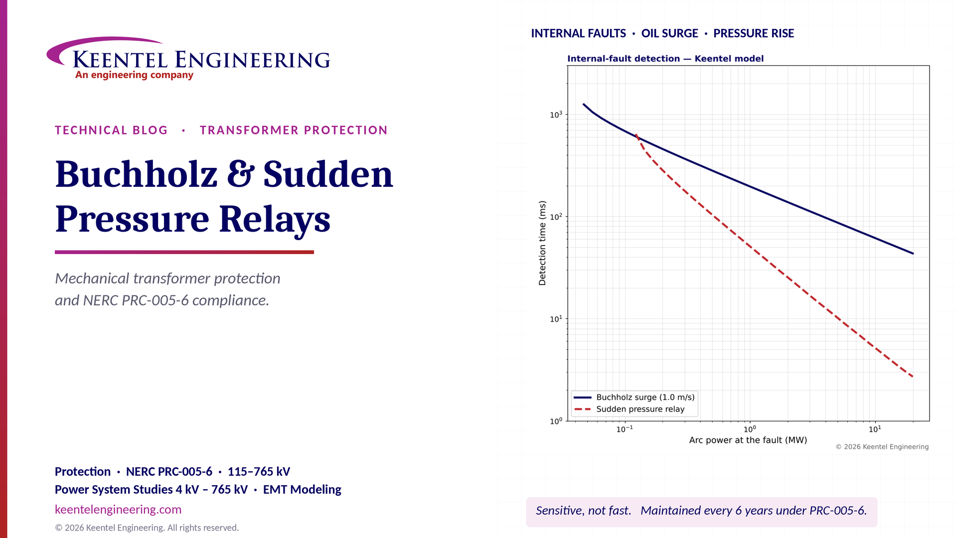
Keentel Engineering built a lumped model of an internal arc in a conservator-type transformer: gas generated at about 70 cm³ per kJ of arc energy, tank and oil compliance, and oil inertia and friction in an 80 mm (about 3 inch) connecting pipe. The model computes when the oil velocity reaches a Buchholz surge setting and when a rate-of-rise pressure element would operate.
| Arc power | Buchholz surge at 1.0 m/s | Sudden pressure element (illustrative) |
|---|---|---|
| 0.05 MW | Does not operate (steady velocity only 0.7 m/s) | Does not operate |
| 0.2 MW | ≈ 457 ms | ≈ 283 ms |
| 1 MW | ≈ 196 ms | ≈ 51 ms |
| 5 MW | ≈ 87 ms | ≈ 10 ms |
| 20 MW | ≈ 43 ms | ≈ 3 ms |
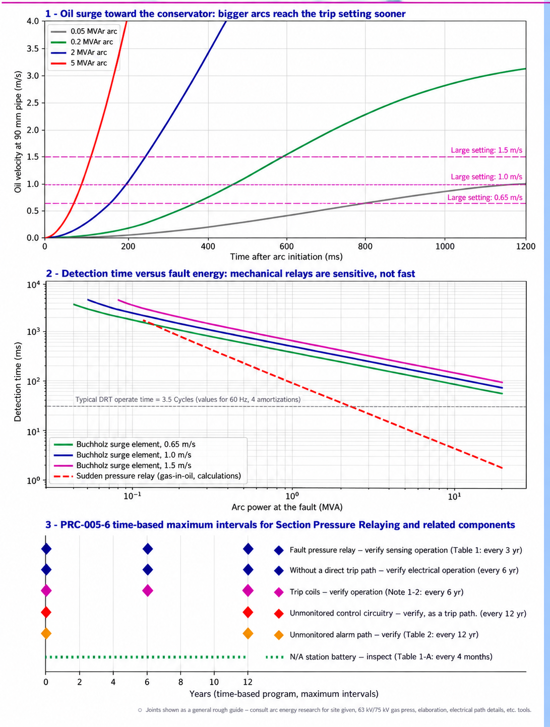
Figure 1. Keentel analysis. Panel 1: oil velocity in the Buchholz pipe for four arc powers. Panel 2: detection time versus arc power for three surge settings and a rate-of-rise pressure element. Panel 3: PRC-005-6 time-based maximum intervals for Sudden Pressure Relaying and related components.
Four lessons
- Mechanical relays are sensitive, not fast. A 0.2 MW arc — small enough to escape a differential relay — still trips a Buchholz relay in under half a second. But for heavy faults, a differential relay operating in about 1 to 1.5 cycles is faster. The two protections complement each other.
- There is a sensitivity floor. For a 1.0 m/s surge setting in an 80 mm pipe, the steady oil velocity reaches the setting only when gas production exceeds the pipe flow area times the setting — about 72 kW of arc power in Keentel's model. Smaller faults rely on the gas-accumulation alarm and dissolved gas analysis.
- Pressure-rate relays are faster for large faults because pressure rises before the oil column accelerates, which is why sudden pressure relays dominate on US sealed-tank designs.
- Maintenance is a compliance obligation. Under PRC-005-6, a fault pressure relay that trips a BES transformer must have its sensing verified at least every 6 calendar years, its lockouts every 6 years and its unmonitored control circuitry every 12 years — or be maintained under a qualifying performance-based program.
Engineering review of a common explanation
Popular explanations of the Buchholz relay often contain errors that matter during testing and troubleshooting.
| Common statement | Keentel's correction |
|---|---|
| "Gas collects in the upper chamber and the float rises to operate the alarm." | Gas displaces oil from the top of the relay housing, so the oil level falls and the upper float drops, closing the alarm contact. Floats rise only when the relay is full of oil. |
| "In a severe fault, a large amount of gas makes the float rise further and operate the trip contact." | The trip element is a separate lower float with a flap (baffle) that is deflected by the oil surge toward the conservator. It also operates if oil is lost and the lower float drops. It does not depend on gas volume in the relay. |
| "Gas is automatically released through the gas vent to the conservator." | Gas is trapped in the relay housing for inspection and sampling through a test cock or gas sampling device. Only after the housing is full of gas does further gas pass up the pipe to the conservator. Analyzing the trapped gas is a key diagnostic step. |
| "Oil flows smoothly through the relay under normal conditions." | Under normal conditions oil moves only slowly as it expands and contracts with temperature. The relay must not operate on these flows or on oil movement from cooling pumps, through-faults or energization. |
| "The Buchholz relay is a fast fault-detection device." | It is sensitive but relatively slow: typically 50 to 300 ms or more, depending on fault energy. It supplements, not replaces, differential protection. |
| "Widely used in power transformers." | Widely used on conservator-type transformers worldwide and increasingly in the US on large units. Many US transformers use sealed tanks or nitrogen blankets without a conservator and therefore use sudden pressure relays instead. |
Part B — Mechanical Protection of Power Transformers: Buchholz Relays, Sudden Pressure Relays and NERC PRC-005-6 Compliance
1. The role of mechanical protection
1.1 Faults that electrical protection struggles to see
Consider a turn-to-turn fault in the high-voltage winding of a 230/115 kV, 300 MVA autotransformer. If a single turn of a 1,000-turn winding is shorted, the shorted turn carries a very large circulating current, but the terminal current changes only by roughly the ratio of the shorted turns to the total — a fraction of a percent of rated current in the early stage. A differential relay with a minimum pickup of 0.3 pu and a 25% to 40% slope cannot detect it. Meanwhile the arc in the shorted turn is dissipating tens to hundreds of kilowatts into the oil.
The basic relationship is the turns ratio between the fault loop and the winding:

where nf is the number of shorted turns, N is the winding turns and If,loop is the current in the shorted loop. With nf/N = 0.001 and a loop current of 20 times rated, the terminal change is only about 0.02 pu.
| Fault type | Electrical signature | Mechanical signature |
|---|---|---|
| Turn-to-turn fault, few turns | Very small terminal current change | Arc gas and pressure; often detected by Buchholz or sudden pressure relay |
| Core fault, shorted laminations or core-to-ground loop | Little or none | Gas from overheating; Buchholz alarm and dissolved gas analysis |
| Loose connection or contact overheating | None until failure | Thermal gases; gas accumulation alarm |
| Partial discharge | None | Hydrogen; slow gas; dissolved gas analysis |
| Winding-to-ground fault near neutral | Small in resistance- or impedance-grounded systems | Arc gas and surge |
| Major winding or lead fault | Large; differential operates | Large surge and pressure rise |
| Loss of oil (leak) | None | Buchholz lower float drop; low oil level gauge |
1.2 IEEE guidance
IEEE C37.91, the guide for protecting power transformers, recognizes gas accumulation relays, sudden pressure relays and pressure relief devices as important supplements to electrical protection, particularly for low-level internal faults. IEEE C57.104 (2019) governs interpretation of dissolved gases. IEEE C57.12.00 sets general transformer requirements, and IEEE C57.152 covers diagnostic field testing after a protective operation.
2. US transformer oil-preservation systems and which relays apply
| Oil preservation system | Description | Typical mechanical relays |
|---|---|---|
| Sealed tank with gas space | Gas cushion above the oil absorbs expansion; tank sealed from atmosphere | Gas-space rapid pressure rise relay; pressure relief device |
| Inert gas pressure (nitrogen blanket) | Nitrogen at regulated positive pressure above oil | Rapid pressure rise relay; pressure relief device |
| Conservator (free-breathing or with bladder/diaphragm) | Separate expansion tank above the main tank, connected by a pipe | Buchholz relay in the connecting pipe; under-oil sudden pressure relay; pressure relief device |
| Conservator with separate tap-changer compartment | Tap changer has its own oil and small conservator | Main-tank Buchholz plus tap-changer oil surge relay |
US practice historically favored sealed and nitrogen-blanketed designs, which is why sudden pressure relays are the dominant mechanical protection in the US fleet. Conservator designs with rubber bladders are now common on large transformers, especially 345 kV, 500 kV and 765 kV units and generator step-up transformers, so many US owners operate both relay types.
3. How faults generate gas
3.1 Oil and cellulose decomposition
| Gas | Primary source | Typical fault indication |
|---|---|---|
| Hydrogen (H2) | Partial discharge, low-energy discharge, all faults | Corona, partial discharge |
| Methane (CH4) and ethane (C2H6) | Oil overheating at lower temperatures (roughly 150 to 300 °C) | Low-temperature thermal faults |
| Ethylene (C2H4) | Oil overheating at higher temperatures (above about 300 to 700 °C) | High-temperature thermal faults, hot joints, circulating currents |
| Acetylene (C2H2) | Arcing (above about 700 °C to well over 1,000 °C) | Arcing, high-energy discharge |
| Carbon monoxide (CO) and carbon dioxide (CO2) | Cellulose (paper) degradation | Overheated insulation |
Temperature ranges are approximate and overlap; interpretation methods such as the Duval triangle and the methods in IEEE C57.104 consider gas ratios and rates of change together.
3.2 Gas yield of arcs
High-energy arcs in mineral oil produce on the order of 50 to 100 cm³ of gas per kilojoule of arc energy (at standard conditions), predominantly hydrogen and acetylene. Keentel's model uses 70 cm³/kJ. The gas generation rate is therefore approximately:

where Parc is the arc power. A 1 MW arc produces about 70 liters of gas per second — enough to drive oil violently toward the conservator and raise tank pressure.
3.3 Slow gas and dissolution
Slowly generated gas largely dissolves in the oil before reaching the Buchholz relay. Only when the oil near the fault becomes locally saturated, or the generation rate is high enough, do free bubbles rise and collect. This is why a Buchholz gas alarm indicates a fault that is already significant, and why online dissolved gas monitoring detects incipient faults much earlier.
4. The Buchholz relay
4.1 Construction
| Element | Function |
|---|---|
| Housing | Cast body with inspection windows, inserted in the pipe between tank and conservator |
| Upper float (gas element) | Supported by oil; drops when gas displaces oil, closing the alarm contact |
| Lower float with flap (surge element) | The flap is deflected by oil surge above the set velocity; the float also drops on complete oil loss; closes the trip contact |
| Contacts | Magnetically operated reed switches in modern relays; mercury switches in older relays |
| Test cock and gas sampling valve | Release and collect accumulated gas; inject air for testing |
| Test button or mechanical test | Mechanically operate the elements |
| Volume scale on window | Estimate collected gas volume |
4.2 Operating sequence
| Condition | What happens in the relay | Output |
|---|---|---|
| Normal | Relay full of oil; floats up; slow oil movement with temperature | None |
| Slow gas generation | Bubbles rise into relay; oil level falls; upper float drops | Alarm when collected gas reaches set volume |
| Continued gas | Relay housing fills; further gas passes to conservator | Alarm persists |
| Severe internal fault | Oil surge from tank to conservator deflects flap | Trip |
| Severe oil loss | Oil level falls below relay; lower float drops | Trip (and alarm) |
4.3 Typical ratings and installation
| Parameter | Typical values |
|---|---|
| Nominal pipe size | 25 mm (1 in.), 50 mm (2 in.) and 80 mm (3 in.) |
| Gas volume for alarm | About 100 to 300 cm³ |
| Surge (flap) trip settings | About 0.65, 1.0, 1.5 or 2.0 m/s oil velocity, selected by size and cooling |
| Installation | Arrow pointing toward conservator; pipe rising toward conservator at about 1° to 5° (often 2° to 4°) |
| Straight pipe | Several pipe diameters of straight run on each side, per manufacturer |
| Contact rating | Typically suitable for 125 V dc trip and alarm circuits; verify interposing relay needs |
Settings must be chosen with the transformer manufacturer. A setting too low can operate on oil movement when forced-oil pumps start or during through-faults; a setting too high reduces sensitivity.
4.4 Worked example: sensitivity floor of the surge element
The surge element can operate only if the oil velocity in the pipe reaches its setting. In steady state, the volume flow toward the conservator equals the gas generation rate:
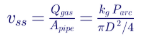
For D = 80 mm, A = 0.00503 m², kg = 70 cm³/kJ and a setting of 1.0 m/s:

Below about 72 kW, the surge element does not operate no matter how long the arc persists; protection relies on the gas element, which needs free gas to collect, and on dissolved gas monitoring.
4.5 Worked example: time to gas alarm
If an incipient fault releases free gas into the relay at a given rate, the time to reach a 200 cm³ alarm volume is:
| Free gas reaching the relay | Time to alarm |
|---|---|
| 10 mL/day | 20 days |
| 50 mL/day | 4 days |
| 200 mL/day | 1 day |
| 1,000 mL/day | About 5 hours |
These rates refer to free gas actually arriving at the relay, which can be a small fraction of the gas generated at the fault.
5. Sudden pressure relays
5.1 Principle
A sudden pressure relay — the device NERC calls a fault pressure relay — responds to the rate of rise of pressure rather than to static pressure. A typical design uses a sensing bellows or diaphragm exposed to tank pressure on one side, and a reference chamber connected through a small equalizing orifice on the other. Slow pressure changes from temperature or load equalize through the orifice; a rapid rise produces a differential pressure that operates a microswitch.
The behavior can be approximated as a first-order lag:

The relay operates when the differential reaches its setting. For a constant rate of rise r, the differential approaches rτ, so the relay has an effective minimum operating rate:

Above this rate, operating time falls as the rate increases. Manufacturers publish operating curves of time versus rate of rise; Keentel's model uses illustrative values of a 7 kPa (about 1 psi) differential setting and a 2-second equalizing time constant, giving a minimum operating rate of about 3.5 kPa/s (0.5 psi/s).
5.2 Gas-space and under-oil relays
| Type | Mounting | Characteristics |
|---|---|---|
| Gas-space rapid pressure rise relay | Above oil in sealed or nitrogen-blanketed tanks | Responds to gas cushion pressure; affected by gas volume and temperature |
| Under-oil fault pressure relay | Below oil level, on a tank wall valve | Responds directly to oil pressure wave; faster; can be mounted on conservator transformers |
5.3 Worked example: pressure rise in a gas cushion
For a sealed tank with a gas cushion of volume Vg at absolute pressure p0, gas generation Q compresses the cushion approximately isothermally:
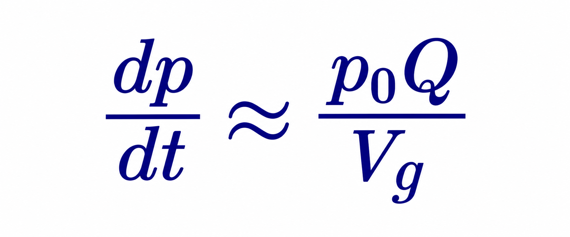
With p0 = 101.3 kPa, Vg = 3 m³ and a 1 MW arc producing 0.07 m³/s:

This is a relatively slow rate for a gas-space relay because the cushion absorbs the pressure, which is one reason under-oil relays respond faster. The real pressure wave near the fault is much faster and larger than this average estimate, because oil is nearly incompressible and the tank walls take time to deflect.
5.4 Misoperation risks
Sudden pressure relays have a mixed history of misoperation, which led many US utilities in past decades to use them for alarm only. Common causes include:
| Situation | Penalty basis | Illustrative penalty |
|---|---|---|
| Transitional cluster withdrawal | Nine times study costs | ≈ $2.29 million |
| Regular cluster, withdrawal during cluster study | Two times allocated study costs (or study deposit, if greater) | ≈ $0.51 million |
| Regular cluster, after restudy, before facilities study | 5% of estimated network upgrade costs | 5% × $178M = $8.9 million |
| Regular cluster, during facilities study or after draft agreement | 10% of estimated network upgrade costs | $17.8 million |
| Regular cluster, after agreement execution | 20% of estimated network upgrade costs | $35.6 million |
IEEE C37.91 and industry reports describe supervision schemes. A common approach requires the sudden pressure relay contact and an independent electrical indication — for example, an instantaneous overcurrent or differential element pickup, or a neutral current detector — before tripping. Supervision must be designed so that it does not block tripping for the low-level faults that the sudden pressure relay exists to detect; a supervision element set too high defeats the purpose.
5.5 Worked example: operating time versus rate of rise
For a constant rate of pressure rise r, the first-order model gives a differential pressure that builds as:
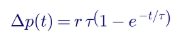
so the operating time for a setting Δpset is:
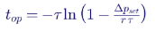
With Δpset = 7 kPa and τ = 2 s (illustrative values):
| Rate of rise | Rate (psi/s, approx.) | Operating time |
|---|---|---|
| 3.5 kPa/s or less | 0.5 or less | Does not operate |
| 5 kPa/s | 0.7 | ≈ 2.4 s |
| 10 kPa/s | 1.5 | ≈ 0.86 s |
| 20 kPa/s | 2.9 | ≈ 0.39 s |
| 50 kPa/s | 7.3 | ≈ 145 ms |
| 200 kPa/s | 29 | ≈ 35 ms |
| 1,000 kPa/s | 145 | ≈ 7 ms |
The curve explains the relay's two personalities: very slow and insensitive to gradual changes such as thermal expansion, and very fast for the steep pressure fronts of high-energy faults. When testing, the test kit must deliver a rate of rise above the minimum operating rate; a test at too low a rate will fail a good relay, and recording the applied rate is good practice. Actual characteristics differ by manufacturer and model, so procedures must use the manufacturer's published curve and test values.
5.6 Application checklist for sudden pressure relays
| Item | Good practice |
|---|---|
| Location | On the main tank, away from pump discharges and cooler headers, at the manufacturer's recommended elevation |
| Isolation valve | Install a valve so the relay can be tested and replaced without draining the transformer |
| Seismic rating | Use seismically qualified relays in seismic zones, consistent with IEEE 693 practice for substation equipment |
| Wiring | Weatherproof terminal box, sealed conduit, drip loops, separate trip and alarm cables where practical |
| Interposing relay | Use a fast, high-burden auxiliary relay if the relay contact rating or cable length requires it, avoiding nuisance pickup from cable capacitance |
| Supervision | Decide on supervision philosophy with documented sensitivity analysis |
| Monitoring | Trip circuit supervision for PRC-005-6 monitoring credit |
| Event recording | Wire the trip contact to the transformer event recorder or digital relay input |
6. Keentel's surge and pressure model
6.1 Equations
The model represents the tank as a compliance C (combining oil compressibility and tank wall flexibility), the
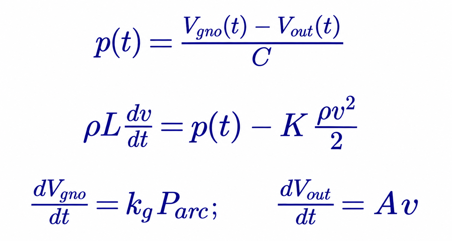
with ρ = 870 kg/m³, L = 3 m, D = 80 mm, K = 3 and C = 5 × 10⁻⁷ m³/Pa.
6.2 Results and interpretation
| Arc power | Gas rate | Buchholz 0.65 m/s | Buchholz 1.0 m/s | Buchholz 1.5 m/s | Pressure element |
|---|---|---|---|---|---|
| 0.1 MW | 7 L/s | ≈ 524 ms | ≈ 683 ms | ≈ 934 ms | Below minimum rate |
| 0.2 MW | 14 L/s | ≈ 360 ms | ≈ 457 ms | ≈ 586 ms | ≈ 283 ms |
| 1 MW | 70 L/s | ≈ 157 ms | ≈ 196 ms | ≈ 243 ms | ≈ 51 ms |
| 5 MW | 350 L/s | ≈ 70 ms | ≈ 87 ms | ≈ 107 ms | ≈ 10 ms |
Values are read from the model and rounded. They show the trends, not design values: the lower the surge setting, the more sensitive and faster the relay, but the greater the risk of operation on non-fault oil movement. Real transformers have more complex geometry, multiple oil paths and nonlinear tank deflection; manufacturer data and field experience govern settings.
The model's predicted tank pressures at high arc power — hundreds of kilopascals within a few hundred milliseconds — also illustrate why fast electrical clearing matters. Transformer tanks and pressure relief devices are designed for modest overpressure; a high-energy fault left uncleared for several cycles can rupture a tank and start a fire, which NFPA 850 and utility fire protection practices seek to prevent.
7. An integrated transformer protection scheme
| Protection | Device | Function | Speed | Sensitivity to low-level internal faults |
|---|---|---|---|---|
| Differential | 87T | Primary protection for internal faults | ≈ 1 to 1.5 cycles | Limited by pickup and slope |
| Restricted earth fault | 87N (REF) | Ground faults near the neutral of wye windings | ≈ 1 to 2 cycles | High for ground faults |
| Buchholz surge | 63 (trip) | Internal faults producing oil surge; oil loss | ≈ 50 to 500 ms | High |
| Buchholz gas | 63 (alarm) | Slow gas accumulation | Hours to days | Very high for gassing faults |
| Sudden pressure | 63SPR | Internal faults producing rapid pressure rise | ≈ 1 cycle to several hundred ms | High |
| Pressure relief | 63PRD | Static overpressure venting | Mechanical | Not a fault detector |
| Overcurrent | 50/51 | Backup for external and internal faults | Coordinated | Low |
| Thermal | 49, 26 | Overload and cooling failure | Minutes | Not a fault detector |
| Oil level | 71 | Low oil | Slow | Not a fault detector |
| Lockout | 86T | Trips and blocks closing of all transformer breakers | Milliseconds | — |
7.1 Tripping design considerations
- Mechanical relay trips typically operate the transformer lockout relay (86T), which trips all breakers and blocks reclosing until reset.
- Breaker failure initiation from mechanical relays requires care, because breaker failure schemes usually rely on current detectors that may not pick up for low-level faults. Some designs use breaker auxiliary contact logic for these trips.
- Contacts on the transformer are exposed to harsh environments. Interposing auxiliary relays, sealed cable entries and trip circuit monitoring improve reliability.
- Event recording of mechanical relay operations, with time stamps, supports post-event analysis and misoperation investigation.
8. NERC PRC-005-6 in depth
8.1 Purpose and scope
PRC-005-6, "Protection System, Automatic Reclosing, and Sudden Pressure Relaying Maintenance," requires applicable entities to document and implement maintenance programs so that these systems remain in working order. Sudden Pressure Relaying was added in PRC-005-6, following FERC's directive to address it after recognizing that fault pressure relays, although not part of the defined Protection System, trip BES Elements and must be maintained.
8.2 Definitions
| Term | NERC definition (summarized) |
|---|---|
| Sudden Pressure Relaying | A system that trips an interrupting device to isolate the equipment it monitors, consisting of a fault pressure relay and its associated control circuitry |
| Fault pressure relay | A mechanical relay or device that detects rapid changes in gas pressure, oil pressure or oil flow indicative of faults within liquid-filled, wire-wound equipment |
| Unresolved Maintenance Issue | A deficiency found during maintenance that causes the Component not to meet intended performance and cannot be corrected during the maintenance interval |
| Countable Event | A Component failure requiring repair or replacement, a condition found requiring corrective action, or a Misoperation due to hardware or calibration failure |
The Buchholz surge (trip) element and sudden pressure relays that trip BES Elements fall within this definition. Gas accumulation elements used only for alarm, and thermal or oil-level devices, do not.
8.3 Applicability
PRC-005-6 applies to Transmission Owners, Generator Owners and Distribution Providers for the systems that protect BES Elements. For transformers, this generally means Sudden Pressure Relaying that trips interrupting devices isolating BES transformers — for example, transmission transformers with primary and secondary terminals at 100 kV or above (such as 345/138 kV and 230/115 kV autotransformers) and generator step-up transformers of BES generating units. Dispersed generating resources are covered as specified in the standard. Each entity must confirm applicability against the BES definition and its registration.
8.4 Requirements
| Requirement | Summary |
|---|---|
| R1 | Establish a Protection System Maintenance Program (PSMP) that identifies, for each Component Type, whether maintenance is time-based, performance-based or a combination, and documents monitoring attributes used to justify intervals |
| R2 | For performance-based maintenance, follow Attachment A |
| R3 | For time-based maintenance, perform the activities in the tables within the maximum intervals |
| R4 | For performance-based maintenance, implement and follow the program |
| R5 | Demonstrate efforts to correct Unresolved Maintenance Issues |
8.5 Table 5 — Sudden Pressure Relaying
| Component | Maximum interval | Minimum maintenance activity |
|---|---|---|
| Fault pressure relay | 6 calendar years | Verify the pressure or flow sensing mechanism is operable |
| Electromechanical lockout and tripping auxiliary devices in the direct trip path from the fault pressure relay | 6 calendar years | Verify electrical operation |
| Unmonitored control circuitry associated with Sudden Pressure Relaying | 12 calendar years | Verify all paths of the trip circuits, including auxiliary relays, through to the trip coils |
| Control circuitry monitored and alarmed for continuity and power | No periodic maintenance specified | Monitoring with alarm meeting the standard's criteria |
Related components also apply: trip coils of the interrupting devices (Table 1-5, 6 calendar years), station dc supply (Table 1-4, with 4-month, 18-month and longer activities depending on battery type) and alarm paths (Table 2).
8.6 What "verify the sensing mechanism is operable" means in practice
The standard does not prescribe a test method. Common approaches:
| Device | Typical verification |
|---|---|
| Buchholz surge element | Operate the flap mechanically with the test device; where possible, verify with a flow test; confirm contact operation and trip output |
| Buchholz gas element (if included in program) | Inject air through the test cock until the upper float drops; confirm alarm |
| Under-oil sudden pressure relay | Isolate from tank with the valve; apply a controlled rate of pressure rise with a test kit through the test port; confirm operation and, where specified, operating time |
| Gas-space rapid pressure rise relay | Apply pressure rise through the test port; confirm operation |
Evidence should show the device, date, method, as-found and as-left condition, and the person performing the test.
8.7 Performance-based maintenance
Attachment A allows longer intervals based on demonstrated performance:
- define segments of similar Components with at least 60 Components in each segment;
- maintain on time-based intervals until at least 30 Components have results;
- set intervals so that Countable Events occur on no more than 4% of Components;
- maintain at least the greater of 5% of the segment or 3 Components each year;
- analyze results annually; if Countable Events reach 4% or more, implement an action plan to get below 4% within 3 years.
8.8 Worked example: performance-based segment
A utility owns 84 sudden pressure relays of the same make and model on BES transformers. Over the last two years it tested 30 relays and found 3 relays with failed microswitches or blocked orifices requiring replacement.

This exceeds the 4% threshold, so the utility cannot extend the interval. It must keep the segment on an interval that reduces Countable Events below 4% and implement an action plan, such as replacing the aging model. If, after replacement, testing finds 1 Countable Event in 32 relays (3.1%), the segment can support a performance-based interval, subject to annual testing of at least max(5% × 84, 3) = 5 relays.
8.9 Worked example: time-based compliance and VSL exposure
A transmission owner has 40 BES transformers with Sudden Pressure Relaying, each with one fault pressure relay, one lockout device and unmonitored control circuitry — 120 Components. During an audit, 7 Components are found past their maximum interval.
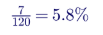
Under the R3 Violation Severity Levels, failing to maintain more than 5% but no more than 10% of Components is a Moderate VSL. Missing 6 Components (5.0%) would have been Lower. A robust maintenance tracking system with automatic warnings well before the maximum interval is the most effective mitigation.
8.10 Evidence and recordkeeping
| Item | Retention (summary) |
|---|---|
| Protection System Maintenance Program | Current version and versions in effect since the last audit |
| Maintenance Records | For intervals longer than the audit cycle, the most recent record; for shorter intervals, all records since the last audit |
| Unresolved Maintenance Issues | All identified since the last audit, with corrective action evidence |
8.11 Practical PSMP design for sudden pressure relaying
- Inventory: list every fault pressure relay that trips a BES Element, with location, model, trip path and associated lockouts and breakers.
- Classify: Component Types — fault pressure relay, lockout, control circuitry — and monitoring status.
- Choose methods: time-based for small fleets; performance-based for large, uniform fleets.
- Write procedures: test methods, equipment, safety, acceptance criteria and evidence forms.
- Schedule: coordinate with transformer outages; many tests require isolating valves or de-energization.
- Track: maintenance management system with due dates well ahead of maximum intervals.
- Correct: document Unresolved Maintenance Issues and corrective actions.
- Review: annual program review and lessons from misoperations.
8.13 Worked example: scheduling a 6-year Sudden Pressure Relaying program
A transmission owner with 42 BES transformers (each with one fault pressure relay and one lockout) wants an even workload. Tests require a transformer outage about half the time, so they must fit the outage plan.
| Planning item | Calculation | Result |
|---|---|---|
| Relays and lockouts per year at the maximum interval | 42 ÷ 6 | 7 transformers per year |
| Planning target with margin (complete by year 5) | 42 ÷ 5 | About 9 transformers per year |
| Unmonitored control circuitry per year at the 12-year interval | 42 ÷ 12 | 3.5 per year; combine with relay tests where trip paths are verified |
| Outage-dependent tests | About 50% of 9 | About 5 outages per year coordinated with the system operator |
| Buffer for missed outages | Keep at least 12 months between planned test date and maximum interval | Reduces risk of a late Component |
Scheduling to complete each cycle in about five years — rather than at the six-year limit — leaves room for cancelled outages, storms and relay replacements. Combining fault pressure relay tests with trip coil (6-year) and dc system activities in the same outage reduces both cost and risk.
8.14 Relationship to other NERC standards
| Standard | Relationship to Sudden Pressure Relaying |
|---|---|
| PRC-004 (Protection System Misoperation Identification and correction) | Sudden Pressure Relaying is defined separately from the Protection System; confirm with your Regional Entity how operations of fault pressure relays are treated, and analyze every operation internally regardless. |
| PRC-005-6 | Maintenance of Sudden Pressure Relaying, Protection Systems and Automatic Reclosing |
| PRC-027 | Coordination of Protection Systems for performance during faults; mechanical relays should be considered in transformer protection reviews |
| FAC-008 | Facility ratings; transformer protection and limiting elements affect ratings documentation |
| TOP and EOP standards | Operating procedures and restoration following transformer trips |
8.15 Status of revisions
PRC-005-6 is the effective version. A NERC project has been developing revisions (proposed PRC-005-7) focused mainly on clarifying applicability to protective functions in excitation systems and other equipment; entities should monitor the project for any changes that affect their programs.
9. Field testing and safety
9.1 Buchholz relay test procedure (typical)
- Obtain clearances and verify the transformer state required by the procedure; many tests can be done energized only with alarm and trip outputs isolated, and only if the manufacturer and owner procedures allow.
- Isolate trip outputs at the test switch, or schedule a transformer outage for full trip testing.
- Inject dry air through the test cock until the upper float operates; record volume and alarm.
- Release air and refill with oil; confirm the float resets.
- Operate the surge element with the mechanical test device; confirm the trip contact.
- Verify the trip path through interposing relays, lockout and breaker trip coils as required by the PSMP.
- Inspect wiring, cable glands and terminal boxes for moisture and damage.
- Restore and document.
9.2 Sudden pressure relay test procedure (typical)
- Close the isolation valve between relay and tank.
- Connect the test kit to the test port.
- Apply a controlled pressure rise; confirm operation; record pressure and, where specified, time.
- Confirm the relay does not operate for slow pressure changes, if the procedure includes this check.
- Vent, reopen the isolation valve and confirm the relay is reset.
- Verify the trip path as required.
9.3 Safety
Work on transformer protection involves energized equipment, stored energy in dc circuits and oil handling. NFPA 70E governs electrical safe work practices, OSHA 29 CFR 1910.269 applies to generation, transmission and distribution work, and the NESC governs clearances. Oil spills must be managed under spill prevention plans.
10. After an operation: diagnosis
10.1 Gas alarm
A Buchholz gas alarm means free gas has collected. Steps:
- Note the volume of gas in the relay and the time since the last observation.
- Collect a gas sample using a gas sampling device; do not ignite gas as a field test.
- Collect an oil sample from the main tank for dissolved gas analysis per IEEE C57.104.
- Compare free gas with dissolved gas using Ostwald coefficients.
- Decide whether the transformer can remain in service, with increased monitoring, or must be removed.
10.2 Worked example: free gas versus dissolved gas
The equilibrium concentration of a gas in oil is approximately the gas-phase concentration times the Ostwald coefficient:

Using typical mineral oil Ostwald coefficients near 25 °C:
| Gas | Relay gas sample (ppm) | Ostwald coefficient (approx.) | Equivalent in oil if in equilibrium (ppm) | Measured in oil (ppm) |
|---|---|---|---|---|
| Hydrogen | 120,000 | 0.06 | 7,200 | 410 |
| Acetylene | 18,000 | 1.2 | 21,600 | 95 |
| Ethylene | 12,000 | 1.7 | 20,400 | 140 |
| Methane | 25,000 | 0.44 | 11,000 | 260 |
| Carbon monoxide | 6,000 | 0.13 | 780 | 520 |
The measured dissolved gases are far below equilibrium with the free gas, meaning gas is being generated faster than it can dissolve — an active, energetic fault. The high acetylene and hydrogen content points to arcing. The transformer should be removed from service for diagnostic testing.
If instead the measured dissolved gases were close to the equilibrium values, the free gas would most likely have evolved slowly from oil that was already gassy, or from a historical event, and the urgency would be lower.
10.3 Trip
After a Buchholz surge or sudden pressure trip, the transformer must not be re-energized until the cause is understood. Typical diagnostics per IEEE C57.152 include dissolved gas analysis, turns ratio, winding resistance, excitation current, sweep frequency response analysis, insulation power factor and capacitance, leakage reactance, and core insulation resistance. A trip with no gas, normal electrical tests and evidence of a wiring fault or mechanical shock points to a misoperation; the cause must still be corrected.
11. Upgrades and modernization
| Upgrade | Benefit |
|---|---|
| Replace mercury-switch relays with reed-switch relays | Removes mercury; better vibration immunity |
| Add trip circuit monitoring | Allows PRC-005-6 "monitored" status for control circuitry, eliminating periodic trip-path verification |
| Add supervision to sudden pressure trips | Reduces misoperation risk while preserving sensitivity |
| Install online dissolved gas monitors | Detects incipient faults long before Buchholz gas alarm |
| Digital Buchholz relays and gas monitors | Measure gas volume continuously and report through SCADA |
| Seismic-rated relays | Reduce operation on ground motion |
| Event recorder inputs | Time-stamped mechanical relay operations for analysis |
12. Common misconceptions corrected
| Misconception | Engineering reality |
|---|---|
| "Buchholz floats rise when gas collects." | Gas displaces oil; floats drop. |
| "Large gas volume operates the trip contact." | The trip element responds to oil surge velocity or oil loss. |
| "Gas is vented automatically." | Gas is trapped for sampling; it reaches the conservator only after the relay is full. |
| "Mechanical relays replace differential protection." | They supplement it; they are slower for heavy faults. |
| "Alarm-only sudden pressure relays are covered by PRC-005-6." | Sudden Pressure Relaying is defined by its trip function; alarm-only devices are not included. |
| "PRC-005-6 requires a specific test method." | It specifies activities and maximum intervals; the entity's procedures define methods. |
| "Supervision always improves sudden pressure relaying." | Poorly set supervision can block the very low-level faults the relay is meant to detect. |
13. Key takeaways
- Mechanical relays detect faults electrical relays can miss, especially low-level turn faults and core faults.
- Understand the elements: gas accumulation alarm, oil surge trip, rate-of-rise pressure trip.
- Correct the physics: floats drop as gas collects; the trip element responds to surge.
- Know the limits: sensitivity floors, operating times and misoperation causes.
- PRC-005-6 applies to trip functions on BES transformers: 6 years for relays and lockouts, 12 years for unmonitored control circuitry, or a qualified performance-based program.
- Diagnose every operation: gas analysis, Ostwald comparison and field testing before re-energizing.
14. How Keentel Engineering helps
Keentel Engineering supports transmission owners, generator owners, renewable and storage developers and industrial facilities with transformer protection and
NERC compliance, from 4 kV to 765 kV.
| Service | Keentel scope | Outcome |
|---|---|---|
| PRC-005-6 program development | PSMP authoring, Component inventory, Sudden Pressure Relaying identification, monitoring attribute documentation | Audit-ready maintenance programs |
| Gap assessments and mock audits | Review of evidence, intervals and Unresolved Maintenance Issue tracking | Reduced compliance risk |
| Performance-based programs | Segment design, Countable Event analysis, interval justification | Optimized maintenance cost |
| Transformer protection design | 87T, 87N, 63, 63SPR, 86T schemes, supervision logic, breaker failure integration | Sensitive, secure protection |
| Relay settings and coordination | Differential, REF, overcurrent and mechanical relay application | Coordinated, documented settings |
| Misoperation analysis | Event review, root cause, corrective action plans | Fewer repeat events |
| Commissioning and testing support | Test procedures, witness testing, trip-path verification | Verified protection from day one |
| Transformer diagnostics support | DGA interpretation, post-trip test planning, return-to-service decisions | Informed asset decisions |
Why clients choose Keentel Engineering
- Protection and compliance under one roof: engineers who design protection and understand NERC standards.
- Practical field knowledge: test procedures that work in substations, not just on paper.
- Audit-ready documentation: programs and evidence structured for Regional Entity audits.
- Transformer expertise: from 13.8 kV distribution transformers to 765 kV autotransformers and generator step-up units.
- Licensed professional engineering: a Florida-registered firm with offices in Tampa, Austin, Sacramento and Baltimore, supporting projects nationwide.
Need a PRC-005-6 program review, sudden pressure relay testing procedures or transformer protection design? Talk to Keentel Engineering at (813) 389-7871, contact@keentelengineering.com, or book a 15-minute scoping call at calendly.com/keentel-engineering/15min.
Part C — Case Studies
The following are illustrative scenarios based on conditions typical of US utilities and generator owners. They show how Keentel Engineering approaches mechanical transformer protection and PRC-005-6 compliance; site details are generalized and figures are rounded.
Case Study 1 — 230/115 kV autotransformer: sudden pressure misoperation on an external fault
Situation. A transmission owner's 230/115 kV, 336 MVA autotransformer tripped by its sudden pressure relay during a close-in 115 kV line fault. The line fault was cleared correctly by line protection. The transformer showed no gas and passed initial electrical tests.
Analysis. Keentel reviews event records and finds that the sudden pressure relay operated about 80 ms after fault inception, during a through-fault of about 12 times transformer rating. The relay was an older model with no through-fault immunity, unsupervised, and installed close to a forced-oil pump discharge. Testing shows its operating rate threshold had drifted lower than the manufacturer's specification.
Engineered solution. Keentel recommends replacement with a current-generation under-oil sudden pressure relay, relocation away from the pump discharge, and supervision by a differential element pickup set low enough to preserve sensitivity for internal faults. The PSMP is updated to include the new relay and its supervision path.
Outcome. The transformer returns to service after diagnostics confirm no internal damage, and subsequent through-faults cause no further operations.
Case Study 2 — 345 kV generator step-up transformer: Buchholz alarm prevents a failure
Situation. A 345 kV generator step-up transformer at a combined-cycle plant receives a Buchholz gas alarm. Plant operators consider resetting the alarm because electrical protection shows no problem.
Analysis. Keentel advises gas sampling and dissolved gas analysis. Free gas is rich in hydrogen and acetylene, and dissolved gases are far below equilibrium with the free gas, indicating an active arcing source. Electrical testing during a planned outage shows abnormal winding resistance on one phase.
Engineered solution. Internal inspection finds a loose and burned lead connection. The connection is repaired, oil is processed, and an online dissolved gas monitor is installed with alarms to the control room.
Outcome. A likely in-service failure is avoided, and the plant gains early warning capability for the remaining life of the transformer.
Case Study 3 — Transmission owner: Sudden Pressure Relaying missing from the PSMP
Situation. During preparation for an audit, a transmission owner discovers that its PSMP covers protective relays, communications, sensing, dc supply and control circuitry, but not Sudden Pressure Relaying on 28 BES transformers.
Analysis. Keentel performs an inventory: 28 transformers, 31 fault pressure relays (some transformers have both Buchholz and sudden pressure trips), 28 lockouts already covered under protective relay control circuitry, and unmonitored trip paths. Several relays have no maintenance records in the past six years.
Engineered solution. Keentel drafts PSMP revisions defining Sudden Pressure Relaying Component Types and methods, writes test procedures for each relay model, and builds a prioritized test plan coordinated with outage schedules. Relays without records are tested first. The client also adds trip circuit monitoring on new installations to simplify future maintenance.
Outcome. The owner brings all Sudden Pressure Relaying within its maximum intervals before the audit, documents its corrective actions, and establishes a sustainable maintenance program.
Part D — Technical FAQ: Buchholz Relays, Sudden Pressure Relays and PRC-005-6
A gas- and oil-actuated relay installed in the pipe between a transformer's main tank and its conservator. It alarms on slow gas accumulation and trips on oil surge or severe oil loss.
It falls. Gas displaces oil from the top of the relay housing, lowering the oil level and dropping the upper float to close the alarm contact.
A flap or baffle on the lower element deflected by oil surging toward the conservator above the set velocity, or the lower float dropping on severe oil loss.
Alarm at about 100 to 300 cm³ of collected gas; surge trip at about 0.65 to 2.0 m/s, depending on pipe size, transformer design and cooling.
It operates in tens to hundreds of milliseconds, slower than differential protection for heavy faults, and it does not detect faults outside the tank such as bushing or lead faults.
A relay that responds to the rate of rise of oil or gas pressure in the tank. NERC calls it a fault pressure relay.
Many US transformers use sealed tanks or nitrogen blankets without conservators, so Buchholz relays cannot be applied. Sudden pressure relays work with any preservation system.
Through-fault forces, energization, pump surges, vibration, seismic events, wiring faults and relay aging can produce pressure waves or false contacts.
By requiring an independent electrical indication, such as a low-set differential or overcurrent pickup, before tripping. Supervision must be sensitive enough not to block low-level internal faults.
Maintenance of Protection Systems, Automatic Reclosing and Sudden Pressure Relaying that protect or affect BES Elements.
A system that trips an interrupting device to isolate the equipment it monitors, consisting of a fault pressure relay and its associated control circuitry.
Yes, when their oil surge or flow element trips an interrupting device for a BES Element. Alarm-only elements are not included.
Fault pressure relays and electromechanical lockouts in the direct trip path every 6 calendar years; unmonitored control circuitry every 12 calendar years; monitored and alarmed control circuitry has no periodic requirement.
No. It specifies minimum activities, such as verifying the sensing mechanism is operable, and maximum intervals. The entity's procedures define how.
Yes, through a performance-based program under Attachment A: segments of at least 60 Components, Countable Events below 4%, and annual testing of at least 5% of the segment or 3 Components.
The current PSMP and prior versions since the last audit, maintenance records showing activities and dates, and records of Unresolved Maintenance Issues and corrective actions.
Sample the free gas and the oil, analyze per IEEE C57.104, compare free and dissolved gases using Ostwald coefficients, and decide on service status based on the results.
Gas is being generated faster than it can dissolve, indicating an active and energetic fault.
Dissolved gas analysis, turns ratio, winding resistance, excitation current, sweep frequency response analysis, insulation power factor and capacitance, leakage reactance and core insulation resistance, per IEEE C57.152.
By adding monitoring and alarming of control circuitry, using performance-based programs for large uniform fleets, and replacing unreliable relay models that generate Countable Events.
References and Further Reading
Links were current at publication (October 2026).
- NERC Reliability Standard PRC-005-6, Protection System, Automatic Reclosing, and Sudden Pressure Relaying Maintenance, and supporting Supplementary Reference and FAQ. North American Electric Reliability Corporation.
- NERC Glossary of Terms Used in NERC Reliability Standards (Protection System, Sudden Pressure Relaying, Countable Event, Unresolved Maintenance Issue). North American Electric Reliability Corporation.
- IEEE Std C37.91, Guide for Protecting Power Transformers. IEEE.
- IEEE Std C37.2, Standard for Electrical Power System Device Function Numbers, Acronyms, and Contact Designations. IEEE.
- IEEE Std C57.104-2019, Guide for the Interpretation of Gases Generated in Mineral Oil-Immersed Transformers. IEEE.
- IEEE Std C57.152, Guide for Diagnostic Field Testing of Fluid-Filled Power Transformers, Regulators, and Reactors. IEEE.
- IEEE Std C57.12.00, General Requirements for Liquid-Immersed Distribution, Power, and Regulating Transformers. IEEE.
- NFPA 70E, Standard for Electrical Safety in the Workplace; NFPA 850, Fire Protection for Electric Generating Plants and High Voltage Direct Current Converter Stations. National Fire Protection Association.
- OSHA 29 CFR 1910.269, Electric Power Generation, Transmission, and Distribution.
- National Electrical Safety Code (NESC), IEEE C2. IEEE.
Disclaimer
his article is general technical information for educational purposes. It is not engineering, legal or compliance advice for any specific facility and does not create a professional relationship. Keentel Engineering's oil-surge and pressure model is a simplified illustration with assumed parameters; actual relay settings, operating times and test methods must follow manufacturer data, transformer design and owner procedures. NERC requirements are summarized; entities must consult the current effective standard, their registration and their Regional Entity, and maintain their own compliance programs. Designs and procedures must follow applicable IEEE standards, the NESC, NFPA codes and OSHA requirements, sealed by a licensed professional engineer where required.
Case studies are illustrative scenarios based on typical project conditions, not records of specific client projects. Figures are rounded and indicative.
NERC, IEEE, NFPA and other names are the property of their respective owners. Keentel Engineering is not affiliated with or endorsed by these organizations or any equipment vendor.
| Office | Address | Phone |
|---|---|---|
| Head Office — Tampa | 400 N Ashley Dr STE #2600, Tampa FL 33602 | (813) 389-7871 |
| Austin | 5900 Balcones Drive STE 100, Austin TX 78731 | (512) 591-0752 |
| Sacramento | 1401 21st St Ste R, Sacramento CA 95811 | (916) 913-4524 |
| Baltimore | 306 W Redwood St STE 200, Baltimore MD 21201 | (410) 225-2181 |

About the Author:
Sandip "Sonny" R. Patel, P.E.
IEEE Senior Member · Founder & CEO, Keentel Engineering
In 1995, Sonny Patel earned his Electrical Engineering degree from the University of Illinois. But degrees don't build legacies — action does.
For three decades, he has worked the power industry from every side of the table: 16 years as a utility engineer at Exelon/Commonwealth Edison; generation leadership across hydroelectric, industrial steam turbine, and a 9 GW renewable fleet; NERC Regional Entity Senior Compliance Engineer and Audit Team Lead, auditing some of the nation's largest utilities; and testing and commissioning lead on equipment up to 765 kV — the very top of the North American grid.Utility. Generator. Regulator. Consultant. Few engineers have seen all four seats. Fewer still have sat in them.
His experience spans nuclear, hydro, conventional generation, renewables, oil and gas, mining — and today's data centers, where he is authoring a three-book series on data center design. He is a Licensed Professional Engineer in six states and a Licensed Electrical Contractor in Florida (Unlimited EC) — he doesn't just design the work; he's qualified to stand behind its execution.Today, as Founder and CEO of Keentel Engineering, Sonny leads a nationwide team of engineers delivering substation design, power system studies, NERC compliance, and commissioning — done right, coast to coast.Three decades. Every side of the table. One standard: accountable engineering.
Services

Let's Discuss Your Project
Let's book a call to discuss your electrical engineering project that we can help you with.
About the Author:
Sandip "Sonny" R. Patel, P.E.
IEEE Senior Member · Founder & CEO, Keentel Engineering
In 1995, Sonny Patel earned his Electrical Engineering degree from the University of Illinois. But degrees don't build legacies — action does.
For three decades, he has worked the power industry from every side of the table: 16 years as a utility engineer at Exelon/Commonwealth Edison; generation leadership across hydroelectric, industrial steam turbine, and a 9 GW renewable fleet; NERC Regional Entity Senior Compliance Engineer and Audit Team Lead, auditing some of the nation's largest utilities; and testing and commissioning lead on equipment up to 765 kV — the very top of the North American grid.
Utility. Generator. Regulator. Consultant. Few engineers have seen all four seats. Fewer still have sat in them.
His experience spans nuclear, hydro, conventional generation, renewables, oil and gas, mining — and today's data centers, where he is authoring a three-book series on data center design. He is a Licensed Professional Engineer in six states and a Licensed Electrical Contractor in Florida (Unlimited EC) — he doesn't just design the work; he's qualified to stand behind its execution.
Today, as Founder and CEO of Keentel Engineering, Sonny leads a nationwide team of engineers delivering substation design, power system studies, NERC compliance, and commissioning — done right, coast to coast.Three decades. Every side of the table. One standard: accountable engineering.
Leave a Comment
Thank you for contacting us.
We will get back to you as soon as possible.
We will get back to you as soon as possible.
Oops, there was an error sending your message.
Please try again later.
Please try again later.
Related Posts
By SANDIP R PATEL
•
October 23, 2026
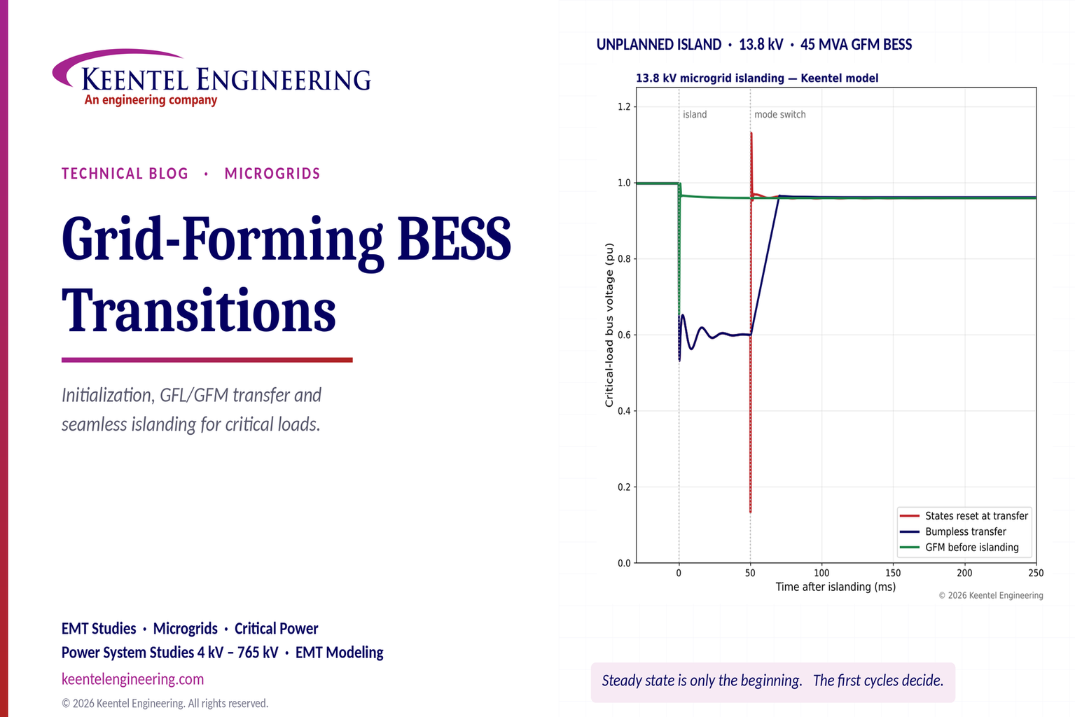
Explore grid-forming BESS initialization, GFL-to-GFM transitions, seamless islanding, EMT simulations, current limiting and microgrid protection.
By SANDIP R PATEL
•
October 23, 2026
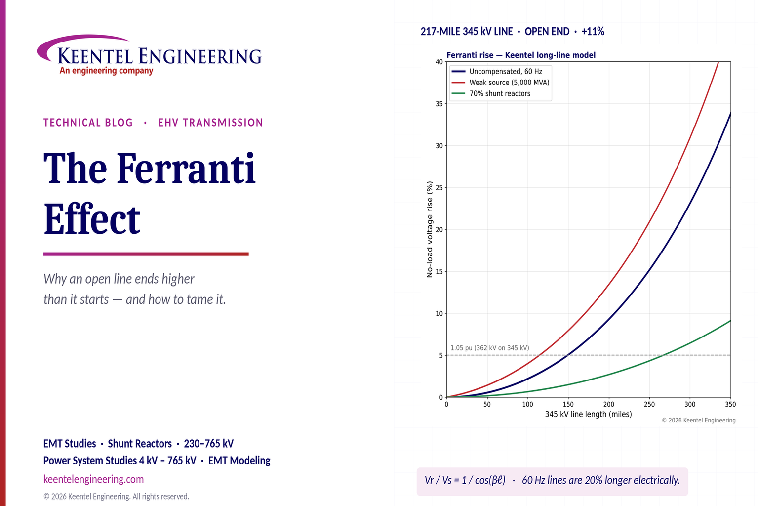
Explore the Ferranti effect in EHV transmission lines: voltage rise, 345 kV examples, switching overvoltages, shunt reactor sizing and mitigation.
By SANDIP R PATEL
•
October 23, 2026
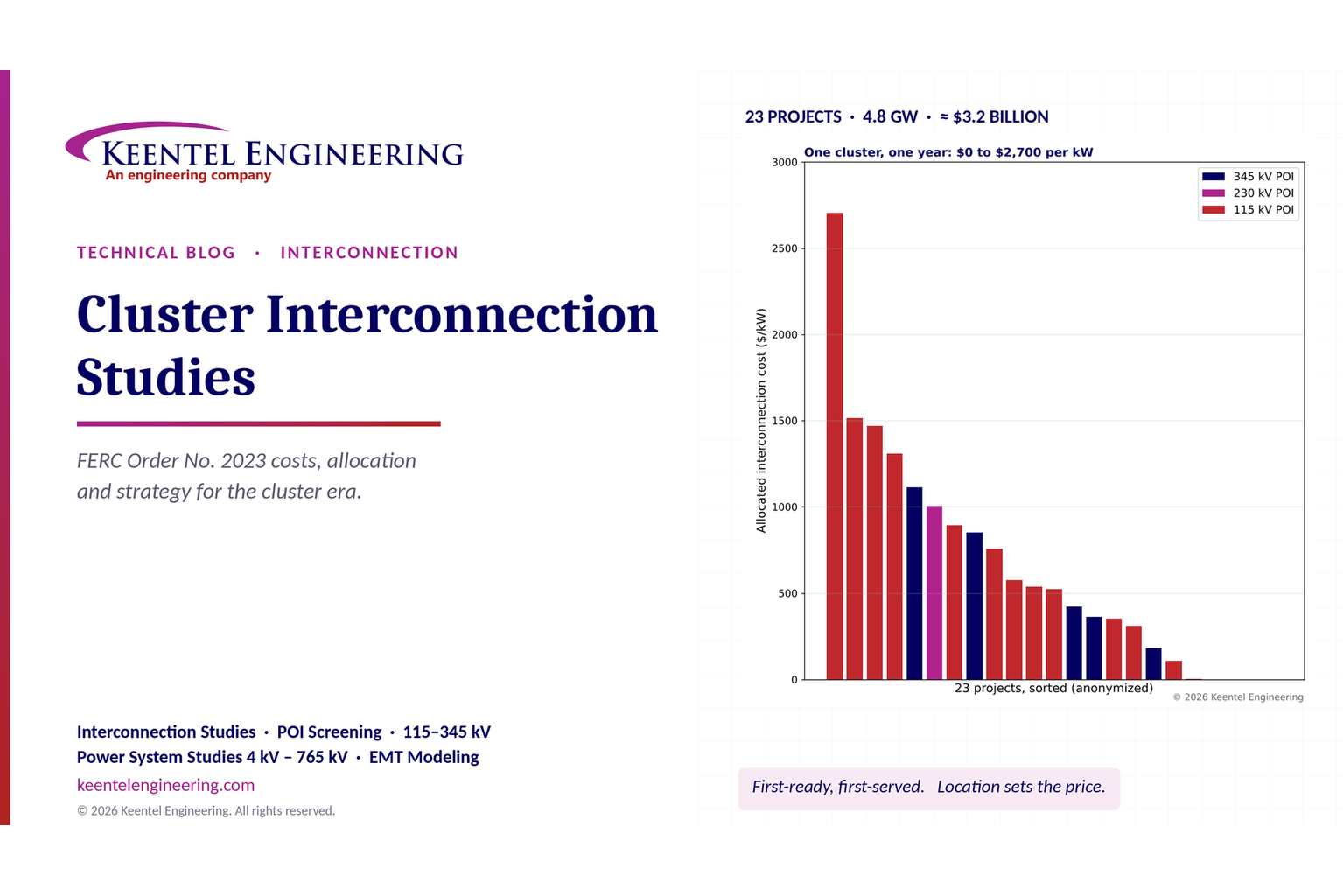
Explore cluster interconnection studies under FERC Order 2023, including network upgrades, cost allocation, withdrawal penalties and developer strategy.
By SANDIP R PATEL
•
October 21, 2026
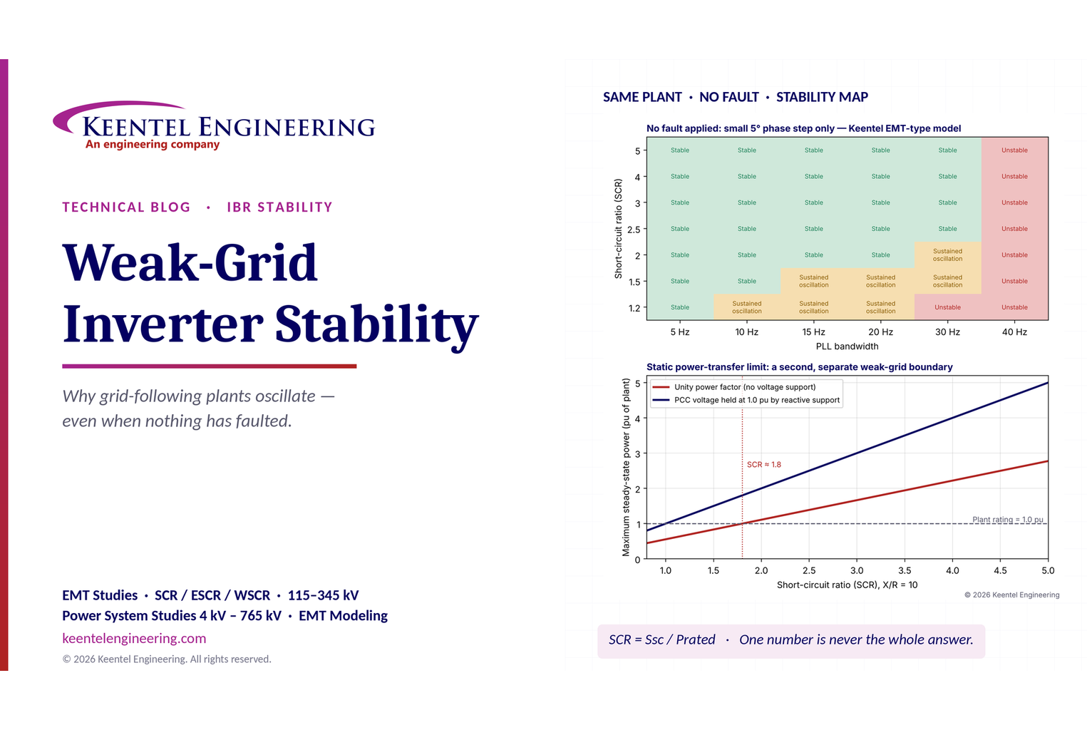
Learn why grid-following inverters become unstable without grid faults. Explore SCR, PLL interactions, EMT studies, grid strength, and mitigation.
By SANDIP R PATEL
•
October 21, 2026
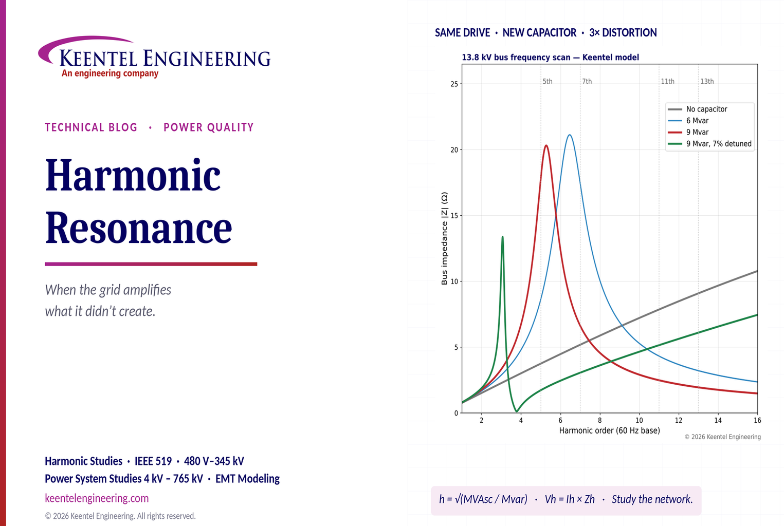
Learn how harmonic resonance amplifies distortion in power systems. Explore capacitor banks, detuned reactors, frequency scans, and IEEE 519 solutions.
By SANDIP R PATEL
•
October 20, 2026
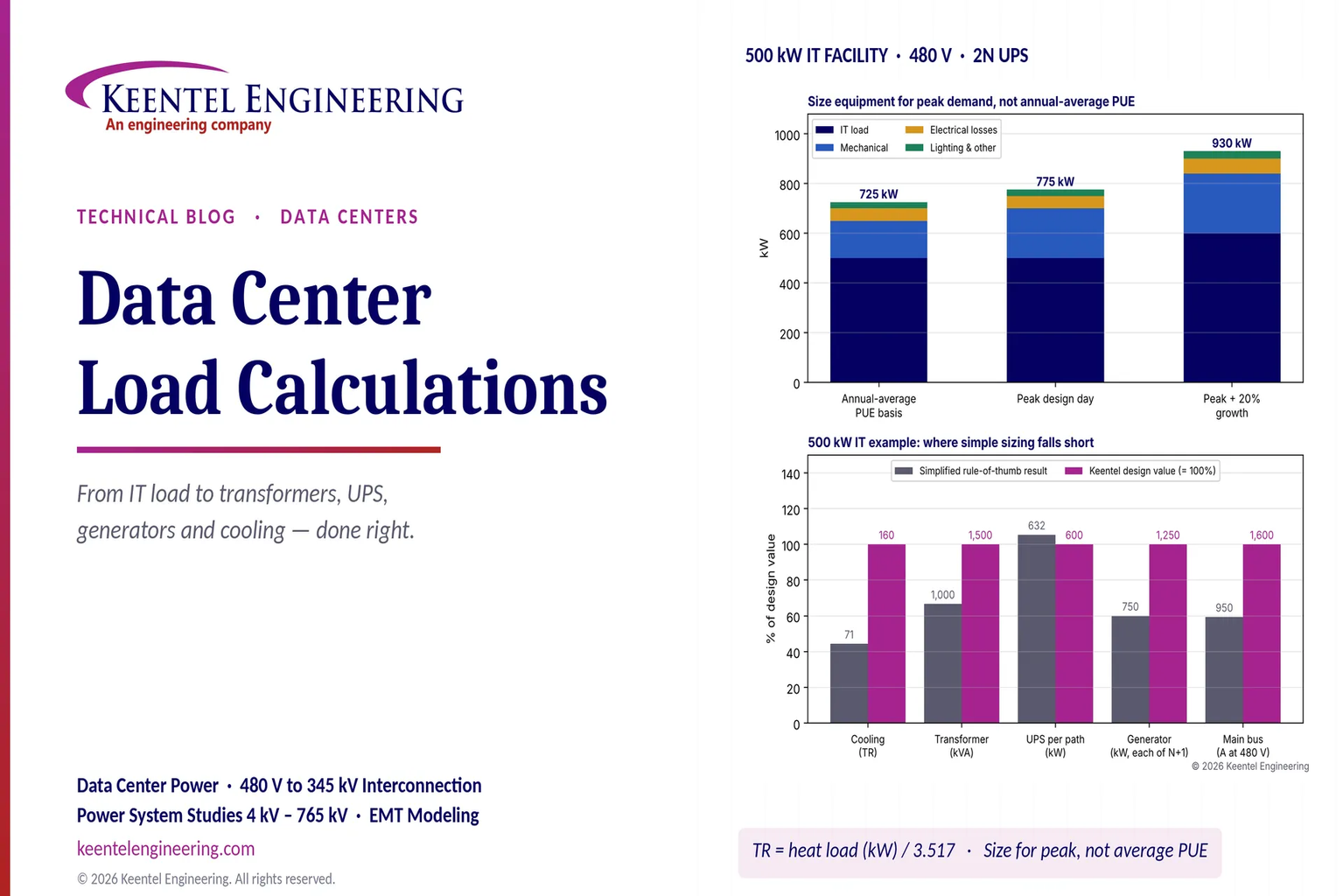
Learn data center electrical load calculations, including IT demand, PUE, UPS and generator sizing, cooling loads, redundancy, and worked US examples.
By SANDIP R PATEL
•
October 20, 2026
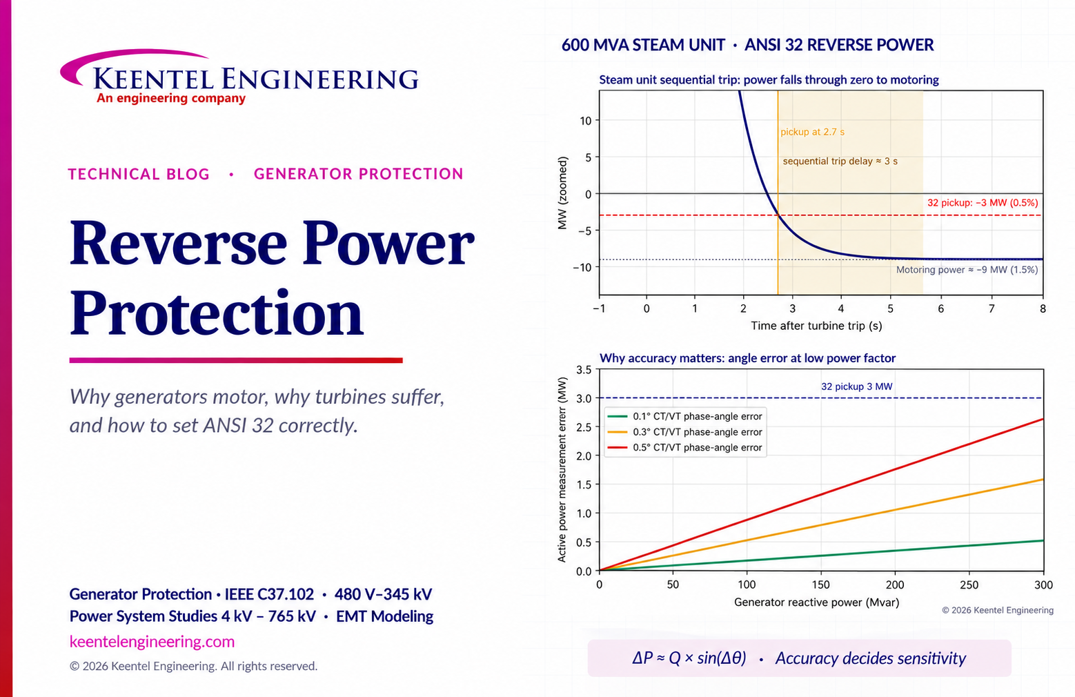
Learn reverse power protection (ANSI 32), generator motoring, relay pickup settings, time delays, sequential tripping and testing for US power plants.
By Team 2 Dexora
•
October 20, 2026
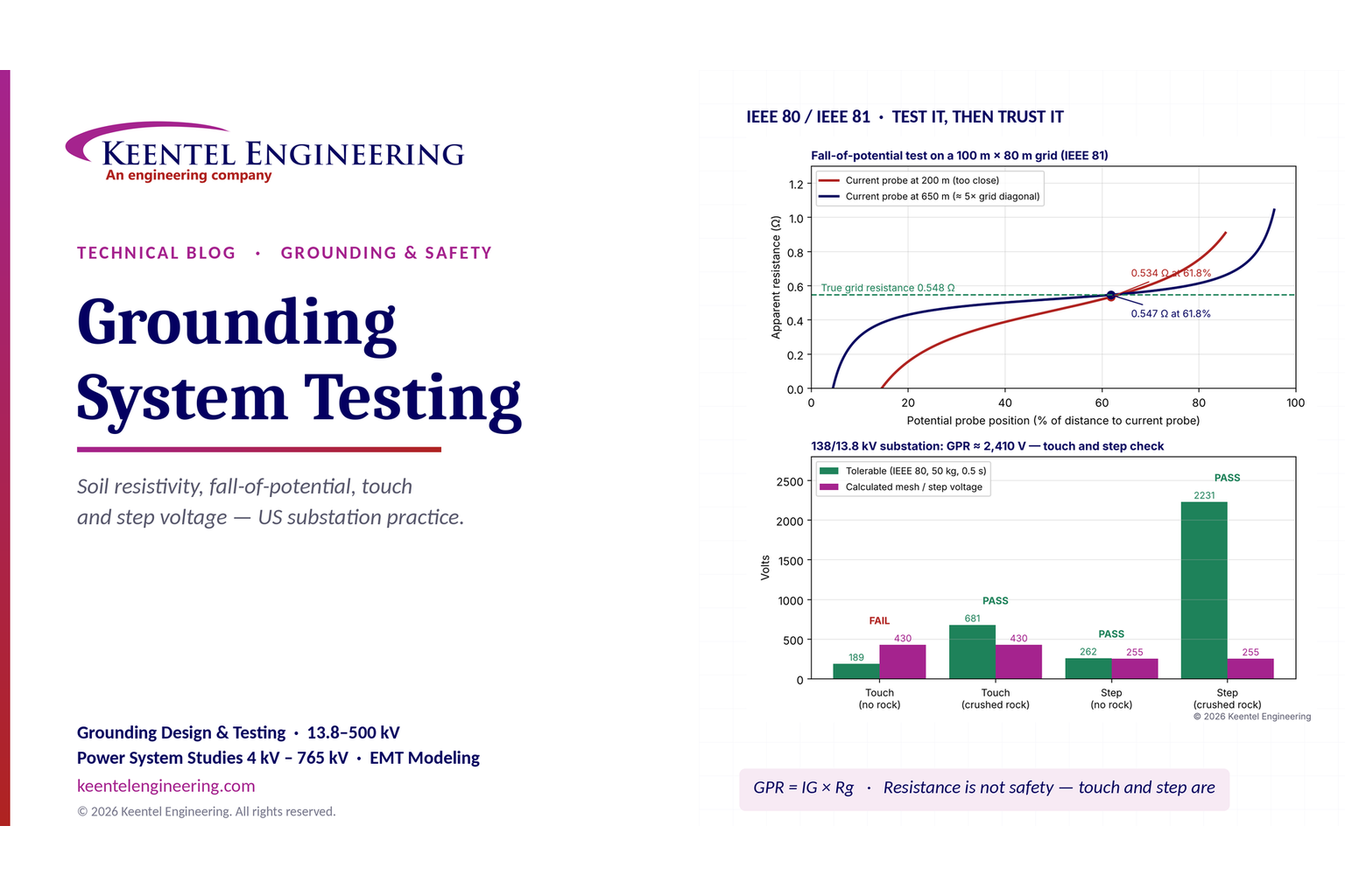
Explore grounding system testing with Keentel Engineering. Learn IEEE 80/81 methods, soil resistivity, ground resistance, and touch and step voltage safety.
By SANDIP R PATEL
•
October 13, 2026
Plan data center capacity with land screening, MW-per-acre estimates, grid power availability and interconnection feasibility studies from Keentel Engineering.