
A Coordinated Electric System Interconnection Review—the utility’s deep-dive on technical and cost impacts of your project.
Challenge: Frequent false tripping using conventional electromechanical relays
Solution: SEL-487E integration with multi-terminal differential protection and dynamic inrush restraint
Result: 90% reduction in false trips, saving over $250,000 in downtime
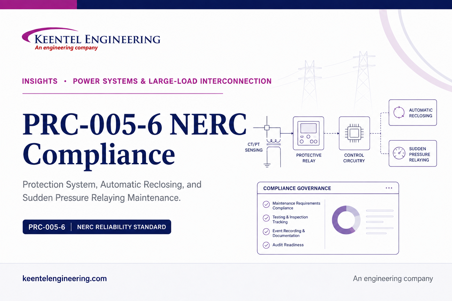
PRC-005-6 NERC Compliance
Aug 12, 2026 | Blog
Protection System Maintenance, Audit Readiness, and Compliance Strategy
Reference Framework
| Reference | How it is used |
|---|---|
| NERC PRC-005-6 | Enforceable requirement language, applicability, maintenance tables, measures, evidence retention, and Attachment A performance-based maintenance criteria |
| PRC-005-6 Implementation Plan | Transition timing and phased implementation framework for newly introduced components and facilities |
| MRO PRC-005-6 Standard Application Guide v2.2a | Industry application guidance, examples of acceptable maintenance evidence, applicability scenarios, and practical testing approaches |
| NERC RSAW PRC-005-6 2016 v3 | Audit-oriented evidence requests, sampling approaches, compliance assessment methods, and common documentation expectations |
This technical resource is organized around the PRC-005-6 materials used for program implementation and audit preparation
1. What PRC-005-6 Covers
The standard applies to Protection Systems, Automatic Reclosing, and Sudden Pressure Relaying identified in the Facilities section. The applicability analysis should begin with the purpose and zone of protection, not simply voltage class or the fact that a device can trip a BES breaker.
1: Protection Systems installed for the purpose of detecting Faults on BES Elements such as lines, buses, and transformers
2: Protection Systems used for applicable underfrequency load shedding and undervoltage load shedding programs
3: Protection Systems installed as a Remedial Action Scheme for BES reliability
4: Applicable generator, generator step-up transformer, station-service transformer, and excitation-transformer protection described by the standard
5: Applicable dispersed generation aggregation Facilities identified by the standard
6: Automatic Reclosing systems meeting the generating-plant, one-bus-away and circuit-mile criteria, or used as an integral part of an RAS
7: Sudden Pressure Relaying that trips interrupting devices to isolate the monitored liquid-filled wire-wound equipment
The MRO application guide is particularly useful when a protection zone includes both BES and non-BES elements. Its practical examples emphasize the purpose of the protection and the zone being protected. A relay that trips a BES device is not automatically in scope if it is installed solely to detect Faults on non-BES elements. Conversely, a scheme protecting a non-BES transformer can be in scope when its zone also detects Faults on a BES bus.
2. The Five Protection System Component Types
For traditional Protection Systems, the program must recognize the five Component Types embedded in the NERC Protection System definition
1: Protective relays that respond to electrical quantities
2: Communications systems necessary for correct operation of protective functions
3: Voltage and current sensing devices providing inputs to protective relays
4: Station dc supply associated with protective functions, including batteries, chargers, and non-battery-based dc supply
5: Control circuitry associated with protective functions through the trip coils of circuit breakers or other interrupting devices
Automatic Reclosing adds four specific elements: the reclosing relay, supervisory relay or function, associated voltage sensing device, and control circuitry. Sudden Pressure Relaying adds the fault pressure relay and its associated control circuitry. A mature asset model must distinguish Component Type from individual Component, because the standard establishes maintenance methods and intervals at the Component Type and Component-attribute level while audit sampling ultimately reaches individual equipment records.
3. Requirement R1 - Build a Defensible PSMP
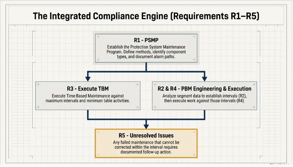
R1 requires the entity to establish a Protection System Maintenance Program for the applicable Protection Systems Automatic Reclosing, and Sudden Pressure Relaying. The PSMP must identify the maintenance method used for each Component Type and identify the monitored Component attributes used when monitoring supports extended intervals or reduced periodic activities.
1: Define the governance boundary: identify accountable organizations, asset data sources, maintenance systems, engineering procedures, and evidence repositories
2: Identify every applicable Component Type and state whether it is maintained using time-based maintenance, performance-based maintenance, or a controlled combination
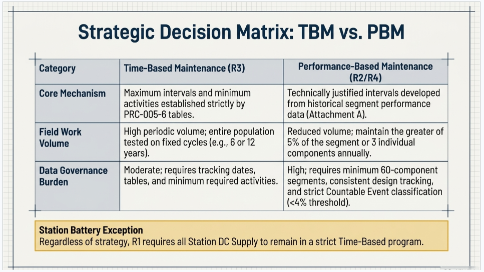
3: Keep station batteries in the required time-based program even if other Component Types use performance-based maintenance
4: For each monitored category, document the exact attribute that satisfies the applicable PRC-005-6 table row
5: Document the alarm path from the alarm origin to the location where corrective action can be initiated, including Table 2 treatment
6: Control revisions to the PSMP and retain superseded versions as required by the evidence-retention provisions
A common weakness is a PSMP that says, in broad terms, that microprocessor relays are monitored. That statement is not enough. The technical basis must identify the actual attributes relied upon, such as internal self-diagnostics, power-supply failure alarming, change-of-settings alarming, ac measurement comparison, monitored binary inputs or outputs, and the associated alarm path. The selected table row should be reproducible from the evidence.
Keentel Engineering service focus: PSMP development and gap review should test not only the written procedure but also whether the asset inventory, relay models, SCADA points, drawings, maintenance frequencies, and evidence repositories support every statement made in the PSMP.
4. Requirement R2 - Performance-Based Maintenance Engineering
R2 applies only where the entity uses performance-based maintenance intervals. Attachment A establishes the technical basis for creating and maintaining a PBM program. PBM can reduce unnecessary periodic work, but it creates a higher analytical and data-governance burden.
4.1 Establishing a PBM Segment
1: Create a Segment with at least 60 individual Components
2: Ensure the Components are of a consistent design standard or a particular model or type from a single manufacturer with common characteristics that support an expectation of consistent performance
3: Continue maintaining the Segment according to the applicable time-based maximum intervals until maintenance results exist for at least 30 individual Components
4: Document the maintenance dates, maintenance results, and Countable Events for each maintained Component
5: Analyze the Segment and establish the maximum allowable interval so Countable Events are no more than 4 percent for the population basis required by Attachment A
4.2 Maintaining the PBM Technical Basis
1: At least annually update Segment lists and descriptions when changes occur
2: Perform maintenance each year on the greater of 5 percent of the Segment population or 3 individual Components
3: Analyze the prior year activities and results
4: Recalculate the maximum allowable interval using prior-year data and the required Countable Event basis
5: When the applicable threshold is exceeded, develop, document, and implement the required action plan and track performance through the recovery period
PBM evidence must allow the auditor to reproduce the Segment population, annual sample count, Countable Event classification, percentage calculation, interval determination, and corrective action decision. If these calculations live only in spreadsheets with no controlled source data or approval workflow, the PBM program becomes fragile during an audit.
5. Requirement R3 - Execute Time-Based Maintenance Correctly
R3 is the core execution requirement for Components in the time-based program. Compliance depends on both the maximum maintenance interval and the minimum maintenance activities in the applicable table row. Performing work on time but omitting one required activity can still create a deficiency.
5.1 Protective Relays
For unmonitored protective relays, the standard establishes a six-calendar-year maximum interval and requires settings verification. Non-microprocessor relays must be tested and calibrated if necessary. Microprocessor relays require verification of essential inputs and outputs and acceptable measurement of power-system input values. Monitored microprocessor relays can use the 12-year categories when the specified monitoring attributes are present.
The MRO guide provides an important practical distinction for microprocessor outputs: viewing an event report may show that logic asserted, but it does not necessarily prove that the physical output contact operated. A defensible test should verify the actual output operation at an appropriate test point, lockout relay, or breaker interface where required by the applicable maintenance activity.
5.2 Communications Systems
Communications systems necessary for correct operation of protective functions require maintenance appropriate to whether channel function and performance are monitored. Unmonitored schemes include relatively frequent functional verification and periodic performance checks. Depending on technology, acceptable performance criteria can include signal level, reflected power, data error rate, or other relevant channel-quality metrics.
5.3 CTs, PTs, and Other Voltage/Current Sensing Devices
For unmonitored voltage and current sensing devices, the maintenance objective is to verify that current and voltage signal values are provided to the protective relays. The MRO guide recognizes both online comparison and appropriately designed offline methods. For assets that cannot reasonably be energized during maintenance, excitation tests, turns-ratio tests, secondary wiring verification, controlled injection, or event-report evidence after energization may provide a defensible engineering basis when properly documented.
5.4 Station DC Supply
Station dc supply requirements are distributed across battery chemistry and monitoring categories. The program must distinguish VLA, VRLA, NiCad, and non-battery energy storage arrangements. The exact activities vary, but may include dc supply voltage verification, electrolyte or physical inspection, ground checks, charger float voltage, continuity, connection resistance, internal ohmic measurements, and periodic capacity or equivalent performance verification. Monitoring under Table 1-4(f) can eliminate certain periodic activities only when the specified monitoring and alarming attributes are actually present and supported by Table 2 alarm-path treatment.
5.5 Control Circuitry
Control circuitry is often where a relay-centric maintenance program becomes incomplete. Table 1-5 addresses trip coils, actuators, lockout devices, RAS control paths, auxiliary relays, and monitored trip circuitry. Auditors may trace a sample beyond the protective relay itself and ask how the entity verifies that the complete trip path remains capable of performing the intended function.
6. Automatic Reclosing - A Distinct PRC-005-6 Risk Area
PRC-005-6 incorporates FERC Order No. 803 direction by including supervisory devices associated with covered Automatic Reclosing. The Component set includes the reclosing relay, supervisory relays or functions that perform voltage or sync-check supervision, associated voltage sensing devices, and the relevant control circuitry.
1: Confirm whether the generating-plant capacity threshold makes Automatic Reclosing at the plant substation applicable
2: Evaluate substations one bus away and less than 10 circuit-miles from the applicable generating plant
3: Identify Automatic Reclosing used as an integral part of an RAS
4: Identify sync-check, undervoltage, and overvoltage supervisory functions associated with the reclosing scheme
5: Do not assume a sync-check relay is in scope if the breaker has no Automatic Reclosing function
6: Where relying on the exclusion based on fault-clearing and generation-loss analysis, retain the engineering study and assumptions that support the exclusion
The MRO application guide demonstrates why topology matters. A location can be physically close to a generating station but still be two buses away and therefore outside a particular criterion. Straight bus, ring bus, and breaker-and-a-half arrangements must be evaluated consistently with the entity engineering basis.
7. Sudden Pressure Relaying
Sudden Pressure Relaying includes the fault pressure relay and its associated control circuitry when the system trips interrupting devices to isolate the monitored equipment. The maintenance activity for a fault pressure relay is to verify that the pressure or flow sensing mechanism is operable at the specified interval. Practical test methods vary by device type and manufacturer.
The application guide notes an important scope distinction: devices that only alarm, and do not trip interrupting devices as part of the defined system, may not meet the standard definition of Sudden Pressure Relaying. The engineering basis should be documented rather than inferred from the device name alone.
8. Requirement R4 - Follow the PBM Program You Established
R4 is the execution counterpart to R2. R2 asks whether the technical basis for PBM was established and maintained correctly. R4 asks whether the entity actually implemented and followed that program for the Components placed in PBM. This distinction is important during audit preparation because an analytically sound PBM program can still fail if maintenance was performed outside the current interval or if mandatory activities were not completed.
1: Maintain a controlled record of the interval in effect for each Segment for each year
2: Schedule and complete required maintenance against the interval actually approved for that Segment
3: Retain Component-level maintenance evidence for sampled items
4: Maintain Table 2 alarm paths when monitoring is used to determine required maintenance activities
5: Ensure interval changes from annual PBM analysis are reflected in the work-management system before due dates are calculated
9. Requirement R5 - Unresolved Maintenance Issues
R5 requires the entity to demonstrate efforts to correct identified Unresolved Maintenance Issues. The standard definition is narrower than a generic maintenance backlog item: the deficiency is identified during a maintenance activity, causes the Component to not meet intended performance, cannot be corrected during the maintenance interval, and requires follow-up corrective action.
A compliant process should establish traceability from the original maintenance record to the issue record and then to the corrective action. Evidence can include work orders, replacement orders, invoices, project schedules with completed milestones, RMAs, purchase orders, procedures, and retest results. The MRO application guide emphasizes that the standard does not impose a universal fixed completion time for every unresolved issue; what matters is documented, credible effort to correct the condition and evidence that progress is being managed.
Audit-readiness principle: Do not close a maintenance record merely because the field crew finished the scheduled visit. If the Component failed a required activity and cannot be restored within the interval, the record should clearly transition into the Unresolved Maintenance Issue process with ownership, dates, corrective actions, and follow-up evidence.
10. Monitoring and Table 2 Alarm Paths
Monitoring is valuable because it can extend intervals or eliminate specified periodic activities, but it also creates a compliance dependency on the alarm path. Table 2 addresses the path by which alarms are conveyed from the alarm origin to a location where corrective action can be initiated.
1: Identify the alarm origin and the specific monitored attribute it represents
2: Identify every communication, gateway, SCADA, EMS, annunciator, or other path element necessary to convey the alarm
3: Confirm the alarm is reported within the timing required by the applicable Table 2 category
4: If the alarm path itself is not monitored, perform the specified periodic verification of alarm conveyance
5: If the alarm path is monitored in a manner that meets the table attributes, retain evidence supporting the no-periodic-maintenance category
6: Define the location where corrective action can be initiated and show that operators or responsible personnel receive the alarm
A frequent compliance gap is proving the relay has self-diagnostics while failing to prove that the diagnostic alarm reaches an actionable location. PRC-005-6 treats these as separate engineering facts.
11. Evidence Retention and Audit Traceability
The standard requires retention of the current dated PSMP and superseded versions since the preceding compliance audit. For R2, R3, and R4, the retention rule depends on the maintenance interval relative to the audit cycle: where the interval is longer than the audit cycle, retain documentation of the most recent performance; where the interval is shorter, retain all performances since the previous scheduled audit date. R5 evidence includes unresolved issues identified since the last audit, including those resolved during that period.
The RSAW goes further from an audit-process perspective by anticipating summary-level inventories, Component counts, maintenance dates, applicable table rows, monitoring attributes, alarm path evidence, and field records for sampled Components. Utilities should design the evidence repository to satisfy that chain before the audit request arrives.
12. Implementation Plan and Transition Controls
The PRC-005-6 Implementation Plan was designed to combine several earlier revisions and phase in newly introduced requirements. For newly introduced Automatic Reclosing Components, Sudden Pressure Relaying Components, and identified dispersed-generation resources, the plan established milestone dates for R1, R2, and R5 and phased R3/R4 compliance according to six-year and twelve-year maximum maintenance intervals.
Although many historical milestones have passed, the implementation plan remains important when reviewing legacy evidence, understanding why a Component first entered the program on a particular date, or reconstructing compliance during an older audit period. A compliance system should preserve historical applicability and maintenance-method decisions rather than overwrite them with only the current state.
13. How an Auditor Is Likely to Test R3
The RSAW describes two practical R3 methods. Large entities may be audited using a sampling-heavy approach in which the auditor first reviews system diagrams and summary data, selects Facilities or Components, and then requests detailed evidence for the sample. Smaller entities may be asked for more complete inventories and records up front.
1: Auditor obtains BES system diagrams or equivalent information to understand the asset population
2: Auditor identifies monitoring-based interval extensions, RAS, UFLS, UVLS, and other populations of interest
3: Auditor selects Facilities or individual Components for testing
4: Entity provides Component identification, location, table row, interval, and maintenance dates
5: Auditor validates the monitoring attributes used to justify the selected row
6: Auditor traces summary records to actual field maintenance or inspection evidence
7: Auditor checks Table 2 alarm path maintenance where applicable
8: Anomalies in the sample can drive expanded sampling or additional evidence requests
14. Common PRC-005-6 Compliance Failure Modes
| Area | Typical weakness | Why it becomes an audit issue |
|---|---|---|
| R1 | PSMP does not explicitly map every Component Type and maintenance method | Auditor cannot confirm that the written program matches the asset population |
| R1 / R3 | Monitored interval claimed without evidence of every required monitored attribute | Extended interval may not be justified |
| R2 | PBM Segment population or annual analysis is incomplete | Technical basis for the performance-based interval cannot be reproduced |
| R3 | Maintenance record shows completion date but not all minimum activities | On-time work may still fail the applicable table requirement |
| R3 | Relay record is complete but associated CT/PT, communications, dc, or control path evidence is missing | Protection System maintenance is broader than the relay itself |
| R4 | PBM interval changed in analysis but work system was not updated | Components may become overdue under the interval actually in force |
| R5 | Failed maintenance result is closed locally without an unresolved-issue record | Entity cannot demonstrate continuing corrective effort |
| Table 2 | Self-diagnostic alarm exists but end-to-end alarm conveyance is undocumented | Monitoring-based relief depends on an actionable alarm path |
15. NERC Compliance Software for PRC-005-6
PRC-005-6 is well suited to a structured compliance data model because the same relationships must be demonstrated repeatedly: Facility to protected Element, Component to Component Type, Component to table row, table row to required activity and interval, monitoring attribute to alarm path, work order to maintenance evidence, and deficiency to corrective action. Keentel Engineering can support the design and implementation of software workflows around these relationships.
15.1 Minimum Software Data Model
1: Unique Component identifier and Component Type
2: Facility, station, protected BES Element, zone of protection, and applicable protection scheme
3: PRC-005-6 applicability determination and engineering basis
4: Maintenance method: TBM, PBM, or controlled combination
5: Applicable table and table row
6: Required activities and maximum interval
7: Monitoring attributes and supporting evidence
8: Table 2 alarm path and alarm-path maintenance status
9: Last maintenance date, due date, completion status, and maintenance evidence links
10: PBM Segment membership and annual analytics where applicable
11: Unresolved Maintenance Issue status, corrective action, and closure evidence
12: Historical changes to applicability, method, interval, Segment, and table-row assignment
15.2 High-Value Software Controls
a: Automated due-date calculations based on calendar-year or calendar-month rules used by the standard
b: Dashboards for approaching maximum intervals and overdue Components
c: Validation rules that prevent a monitored table row from being assigned unless the required monitored attributes are documented
d: Evidence completeness checks before a work order or maintenance event is marked compliance-complete
e: PBM annual-review workflow with Segment population, sample percentage, Countable Event analysis, and approval history
f: R5 aging and milestone dashboards tied directly to the original failed maintenance event
g: Audit sample export that produces the Component, table row, interval, maintenance date, monitoring basis, and evidence links in one package
16. Keentel Engineering PRC-005-6 Compliance Services
Keentel Engineering can support utilities through focused engineering reviews or complete program transformation. The objective is to make the compliance program technically correct, operationally usable, and defensible under RSAW-style audit sampling.
| Service | Technical value |
|---|---|
| Applicability and Scope Review | Review BES Facilities, zones of protection, generator protection, RAS, UFLS, UVLS, dispersed generation, Automatic Reclosing, and Sudden Pressure Relaying; document inclusion and exclusion bases |
| PSMP Development and Revision | Develop or revise the PSMP, Component Type mapping, TBM/PBM methodology, monitoring criteria, responsibilities, evidence controls, and revision governance |
| PRC-005-6 Gap Assessment | Compare current asset inventory, maintenance intervals, procedures, and evidence against the applicable tables and RSAW evidence expectations |
| Maintenance Procedure Review | Map relay, communications, CT/PT, dc supply, control circuitry, Automatic Reclosing, and sudden-pressure procedures to the exact required maintenance activities |
| Monitoring and Alarm Path Validation | Verify monitored attributes, SCADA or EMS alarm paths, Table 2 treatment, and evidence supporting extended intervals or reduced activities |
| PBM Program Engineering | Develop Segments, validate population consistency, classify Countable Events, perform annual analyses, calculate intervals, and create corrective action plans when thresholds are exceeded |
| Audit Readiness and Mock Audit | Build data requests modeled on the RSAW, select representative samples, review evidence quality, conduct SME interviews, identify gaps, and develop remediation actions |
| Compliance Software and Data Architecture | Design asset, maintenance, evidence, PBM, alarm-path, and R5 workflows that make compliance status measurable and audit packages reproducible |
17. Building a Sustainable PRC-005-6 Program
The strongest programs reduce reliance on individual memory. They encode engineering decisions in controlled data, automatically expose approaching due dates, make monitoring dependencies visible, and ensure that evidence is captured at the time maintenance occurs. This lowers both operational risk and audit burden.
1: Establish one authoritative inventory or a controlled reconciliation process among multiple asset systems
2: Assign every applicable Component to a table row and keep the engineering basis for that assignment
3: Treat monitoring as a maintained compliance dependency rather than a one-time design feature
4: Design work procedures so every required maintenance activity produces explicit evidence
5: Build PBM analytics from controlled Component and maintenance data, not ad hoc annual spreadsheets
6: Link failed maintenance activities directly to R5 corrective-action tracking
7: Run periodic mock samples using the RSAW approach before the formal audit cycle
8:
Keep SMEs prepared to explain not only what the program says, but why the engineering method satisfies the applicable PRC-005-6 table
Anonymous Illustrative Case Studies
Important note: The following case studies are anonymous illustrative composites based on common PRC-005-6 compliance conditions. They do not identify a client, facility, project, or location and should not be interpreted as a statement about any specific Keentel Engineering engagement.
Case Study 1 - Rebuilding the R3 Evidence Chain for a Large Protection System Population
Situation
A large registered entity maintained thousands of protective relays across multiple substations. Relay testing was generally current, but the compliance team could not reliably answer a simple RSAW-style question: for a randomly selected BES Element, identify every applicable Protection System Component, the PRC-005-6 table row used, the maintenance interval, the last required activity, and the evidence supporting completion.
Observed Compliance Risks
1: The relay database, work-management system, and protection drawings used different equipment identifiers
2: CT/PT, communications, dc supply, and trip-path records were stored separately from relay records and were difficult to associate with the protected Element
3: Some microprocessor relays were assigned 12-year maintenance intervals without a controlled record proving all monitoring attributes required by the selected table row
4: Summary reports showed a completion date but did not identify which minimum PRC-005-6 activities had been performed
5: Field test files were technically strong but inconsistent in naming, making audit retrieval slow and dependent on individual SMEs
Engineering and Compliance Approach
1: Create a canonical Component identifier and cross-reference legacy names used in relay settings, CMMS records, drawings, and test reports
2: Map each applicable Protection System Component to the protected BES Element and the applicable PRC-005-6 table row
3: Separate the five Protection System Component Types so the audit package covered more than the relay itself
4: Validate monitored table-row assignments against actual relay features, configuration, alarm points, and Table 2 alarm-path evidence
5: Convert the maintenance summary into an activity-level compliance record that showed which required activities were completed on each performance date
6: Build a mock-audit export that reproduced the RSAW sample structure for selected Facilities
Illustrative Result
The redesigned process converted a fragmented maintenance history into a reproducible evidence chain. Instead of searching several systems after an auditor selected a Component, the compliance team could generate the applicable Component list, table-row basis, due-date calculation, work order, test evidence, and monitoring support from a controlled index. The major improvement was not additional relay testing; it was proving that existing maintenance satisfied the exact regulatory activity and could be retrieved consistently.
How Keentel Engineering Can Support This Type of Need
Keentel Engineering can perform asset and evidence reconciliation, create PRC-005-6 table-row mapping, review maintenance procedures against required activities, validate monitoring claims, design audit exports, and conduct representative RSAW-style sampling before the formal audit window.
Case Study 2 - Validating Monitoring-Based Interval Extensions and Table 2 Alarm Paths
Situation
An entity had modernized a significant portion of its relay fleet and used monitored microprocessor categories to support longer maintenance intervals. The engineering team was confident that the relays had self-diagnostics, but the documentation did not consistently show the complete monitored attribute set or demonstrate that each alarm reached a location where corrective action could be initiated.
Observed Compliance Risks
1: The PSMP used the phrase continuously monitored without identifying the specific attributes required by each table row
2: SCADA point lists existed, but there was no controlled relationship between a relay diagnostic alarm and the corresponding PRC-005-6 monitored attribute
3: Some alarm paths crossed substation gateways and communications infrastructure that were maintained by a different organization
4: The team could prove that alarms appeared in an HMI during commissioning, but could not readily prove ongoing Table 2 maintenance treatment
5: No standardized review existed when relay firmware, settings, communications, or SCADA points changed
Engineering and Compliance Approach
1: Develop a monitoring-attribute matrix by Component and table row, including self-diagnostics, power-supply alarming, settings-change alarming, ac measurement comparison, and monitored binary I/O as applicable
2: Trace every relied-upon alarm from origin through the gateway, communications path, SCADA or EMS point, and operator or responsible-personnel destination
3: Classify each alarm path under the appropriate Table 2 category and identify the required periodic verification, if any
4: Collect engineering drawings, relay settings extracts, SCADA point records, test evidence, and operating screenshots as a structured evidence package
5: Introduce change-management controls so modifications to a monitored attribute or alarm path trigger PRC-005-6 review before the longer interval remains in effect
Illustrative Result
The entity was able to distinguish between relays that genuinely satisfied the monitored category and relays that should temporarily remain on an unmonitored maintenance interval until the missing alarm dependency was corrected. This prevented unsupported interval extensions and converted monitoring from an assumption into a maintained compliance control.
How Keentel Engineering Can Support This Type of Need
Keentel Engineering can perform monitored-attribute validation, alarm-path walkdowns, engineering drawing review, SCADA evidence mapping, Table 2 classification, and remediation planning. Compliance software can then preserve the attribute-to-alarm-to-interval relationship and flag assets when evidence becomes incomplete.
Case Study 3 - Strengthening PBM Governance and R5 Corrective-Action Tracking
Situation
A registered entity used PBM for selected mature device populations. The annual maintenance program was active, but Segment lists, Countable Event classifications, interval calculations, and corrective-action records were maintained in separate spreadsheets by different groups. At the same time, failed maintenance activities were sometimes managed through local work orders without a consistent R5 determination.
Observed Compliance Risks
1: Segment populations changed during the year without a controlled record of additions, removals, and continued design consistency
2: The number of Components maintained was available, but the annual 5 percent or 3-Component requirement was not automatically checked
3: Countable Event classification varied among maintenance, protection engineering, and compliance personnel
4: Annual interval calculations could not always be reproduced from the source maintenance events
5: A failed device could appear in the PBM analysis while the related corrective work order was not identified as a potential Unresolved Maintenance Issue under R5
Engineering and Compliance Approach
1: Create controlled Segment master records with Component membership, manufacturer/model basis, population count, and effective dates
2: Define a Countable Event decision tree aligned with the PRC-005-6 definition and retain the source evidence supporting each classification
3: Automate annual checks for the greater of 5 percent of population or 3 Components
4: Generate the annual performance calculation directly from maintained Components and Countable Events, with reviewer approval and an interval effective date
5: Link any maintenance-discovered deficiency requiring follow-up to an R5 evaluation and, where applicable, an Unresolved Maintenance Issue record
6: Track action plans, procurement, engineering, outage milestones, and retest evidence in the same compliance view used for PBM performance analysis
Illustrative Result
The PBM program became reproducible year over year. Segment membership, annual maintenance percentage, Countable Event rate, interval changes, and corrective actions could be explained from the same controlled dataset. The R5 process also became more reliable because failed maintenance activities could not disappear into an unlinked work-order backlog.
How Keentel Engineering Can Support This Type of Need
Keentel Engineering can develop PBM Segment criteria, review historical maintenance and failure data, establish Countable Event governance, perform annual Attachment A analyses, review action plans, and design software workflows that connect PBM analytics with R5 issue management and audit evidence.
Partner with Keentel Engineering for PRC-005-6 Compliance Readiness
PRC-005-6 compliance becomes sustainable when engineering, maintenance, asset data, evidence management, and audit preparation operate as one system. Keentel Engineering can help utilities move from reactive evidence collection to a controlled compliance program that is technically grounded and designed for the way NERC audits are actually performed.
1: PRC-005-6 applicability and gap assessments
2: Protection System Maintenance Program development and revision
3: TBM and PBM engineering support
4: Monitoring attribute and Table 2 alarm-path validation
5: Maintenance procedure and evidence reviews
6: RSAW-based mock audits and audit-response preparation
7: Unresolved Maintenance Issue and corrective-action governance
8: NERC compliance software requirements, data architecture, dashboards, and evidence workflows
Next step:
Keentel Engineering can structure a PRC-005-6 readiness review around your existing PSMP, asset inventory, maintenance records, monitoring architecture, PBM data, and audit history to identify the highest-value corrective actions before the next compliance assessment.
Technical References
1: NERC Reliability Standard PRC-005-6 - Protection System, Automatic Reclosing, and Sudden Pressure Relaying Maintenance
2: Implementation Plan, Project 2007-17.4, PRC-005 FERC Order No. 803 Directive, PRC-005-6
3: Midwest Reliability Organization, PRC-005-6 Standard Application Guide, Version 2.2a, June 4, 2018
4: NERC Reliability Standard Audit Worksheet, PRC-005-6, 2016 v3
5: FERC Order No. 803, as referenced in the PRC-005-6 implementation and audit materials
Regulatory note: NERC Reliability Standards, implementation materials, guidance, and audit practices may be revised. Registered Entities should confirm the version currently approved and enforceable in the applicable jurisdiction and evaluate any Regional Entity-specific expectations.
Technical FAQ - PRC-005-6 Compliance
The following questions are written for protection engineers, maintenance leaders, compliance managers, auditors, and asset-management teams preparing to implement, assess, or defend a PRC-005-6 program.

About the Author:
Sandip "Sonny" R. Patel, P.E.
IEEE Senior Member · Founder & CEO, Keentel Engineering
In 1995, Sonny Patel earned his Electrical Engineering degree from the University of Illinois. But degrees don't build legacies — action does.
For three decades, he has worked the power industry from every side of the table: 16 years as a utility engineer at Exelon/Commonwealth Edison; generation leadership across hydroelectric, industrial steam turbine, and a 9 GW renewable fleet; NERC Regional Entity Senior Compliance Engineer and Audit Team Lead, auditing some of the nation's largest utilities; and testing and commissioning lead on equipment up to 765 kV — the very top of the North American grid.Utility. Generator. Regulator. Consultant. Few engineers have seen all four seats. Fewer still have sat in them.
His experience spans nuclear, hydro, conventional generation, renewables, oil and gas, mining — and today's data centers, where he is authoring a three-book series on data center design. He is a Licensed Professional Engineer in six states and a Licensed Electrical Contractor in Florida (Unlimited EC) — he doesn't just design the work; he's qualified to stand behind its execution.Today, as Founder and CEO of Keentel Engineering, Sonny leads a nationwide team of engineers delivering substation design, power system studies, NERC compliance, and commissioning — done right, coast to coast.Three decades. Every side of the table. One standard: accountable engineering.
Services

Let's Discuss Your Project
Let's book a call to discuss your electrical engineering project that we can help you with.
About the Author:
Sandip "Sonny" R. Patel, P.E.
IEEE Senior Member · Founder & CEO, Keentel Engineering
In 1995, Sonny Patel earned his Electrical Engineering degree from the University of Illinois. But degrees don't build legacies — action does.
For three decades, he has worked the power industry from every side of the table: 16 years as a utility engineer at Exelon/Commonwealth Edison; generation leadership across hydroelectric, industrial steam turbine, and a 9 GW renewable fleet; NERC Regional Entity Senior Compliance Engineer and Audit Team Lead, auditing some of the nation's largest utilities; and testing and commissioning lead on equipment up to 765 kV — the very top of the North American grid.
Utility. Generator. Regulator. Consultant. Few engineers have seen all four seats. Fewer still have sat in them.
His experience spans nuclear, hydro, conventional generation, renewables, oil and gas, mining — and today's data centers, where he is authoring a three-book series on data center design. He is a Licensed Professional Engineer in six states and a Licensed Electrical Contractor in Florida (Unlimited EC) — he doesn't just design the work; he's qualified to stand behind its execution.
Today, as Founder and CEO of Keentel Engineering, Sonny leads a nationwide team of engineers delivering substation design, power system studies, NERC compliance, and commissioning — done right, coast to coast.Three decades. Every side of the table. One standard: accountable engineering.
Leave a Comment
Thank you for contacting us.
We will get back to you as soon as possible.
We will get back to you as soon as possible.
Oops, there was an error sending your message.
Please try again later.
Please try again later.
Related Posts
By SANDIP R PATEL
•
October 20, 2026
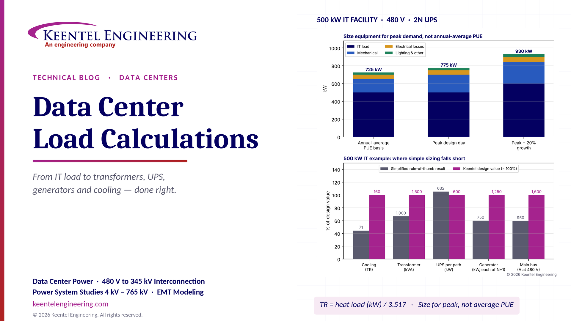
Learn data center electrical load calculations, including IT demand, PUE, UPS and generator sizing, cooling loads, redundancy, and worked US examples.
By SANDIP R PATEL
•
October 20, 2026
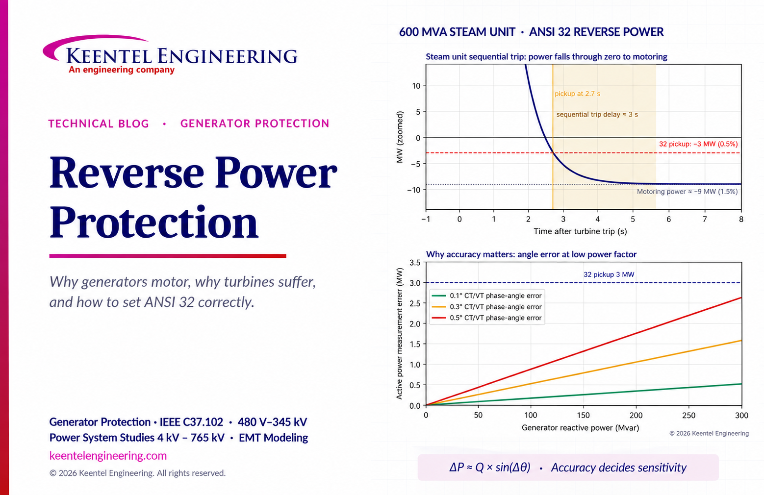
Learn reverse power protection (ANSI 32), generator motoring, relay pickup settings, time delays, sequential tripping and testing for US power plants.
Copy

By Team 2 Dexora
•
October 20, 2026
Explore grounding system testing with Keentel Engineering. Learn IEEE 80/81 methods, soil resistivity, ground resistance, and touch and step voltage safety.

By SANDIP R PATEL
•
October 13, 2026
Plan data center capacity with land screening, MW-per-acre estimates, grid power availability and interconnection feasibility studies from Keentel Engineering.

By SANDIP R PATEL
•
October 11, 2026
Learn which fault produces the highest current at a bus, why SLG faults can exceed three-phase faults, and how symmetrical components determine fault duty.

By SANDIP R PATEL
•
October 11, 2026
Learn why zero-sequence current pulsates in the dq0 frame, how Park's transformation works, and how inverter controls handle unbalance and ground faults.

By SANDIP R PATEL
•
October 11, 2026
Explore grid inertia, RoCoF and frequency response, with swing equation calculations, frequency nadir analysis and US power system simulation examples.

By SANDIP R PATEL
•
October 11, 2026
Learn transient stability analysis, swing equation, equal-area criterion and critical clearing time with a 345 kV worked example and NERC TPL-001 guidance.

By SANDIP R PATEL
•
October 11, 2026
Learn why inverter controls become unstable in weak grids, how PLL bandwidth and SCR affect stability, and how PSCAD EMT studies identify and mitigate oscillations.





