
A Coordinated Electric System Interconnection Review—the utility’s deep-dive on technical and cost impacts of your project.
Challenge: Frequent false tripping using conventional electromechanical relays
Solution: SEL-487E integration with multi-terminal differential protection and dynamic inrush restraint
Result: 90% reduction in false trips, saving over $250,000 in downtime
The three operating regions you have to design to
| Device | Output vs voltage | Response | Best suited to | Main limitations |
|---|---|---|---|---|
| Mechanically switched capacitor or reactor | Proportional to voltage squared | Seconds; discrete steps; limited switching operations per day | Steady-state reactive supply, voltage profile, loss reduction | No dynamic capability; step voltage change on switching; capability collapses when most needed |
| Static var compensator | Capacitive branches proportional to voltage squared | A few cycles; continuously controllable | Continuous control where cost matters and deep voltage support is not the driver | Square-law capability loss; harmonic filters are part of the plant and interact with the network |
| STATCOM | Approximately proportional to voltage — constant current capability | One to two cycles closed loop; converter response faster still | Voltage stability margin, weak interconnections, fast disturbance recovery, flicker and unbalance compensation | Higher capital cost; converter losses; adds a converter and its control dynamics to the network |
| Synchronous condenser | Governed by machine capability and excitation | Excitation response in the hundreds of milliseconds; inherent inertial response instantaneous | System strength and inertia, short-circuit contribution, black start support | Rotating plant with maintenance and losses; slower controlled response than a converter |
| STATCOM with energy storage | Reactive as a STATCOM, plus real power within the storage rating | As STATCOM for reactive; real power limited by storage | Where a real power deficiency is part of the problem | Cost and complexity of the storage; different failure and maintenance profile |
The ±1 Microsecond Question: Time Synchronization for IBR Disturbance Monitoring Compliance

September 25, 2026 | Blog
A Keentel Engineering technical briefing for Generator Owners, asset managers, and compliance teams
The ±1 Microsecond Question: Why Time Synchronization Is the Hidden Compliance Gap in IBR Disturbance Monitoring
Ask a plant owner whether their solar facility can record a grid disturbance, and the conversation usually goes straight to hardware: is there a digital fault recorder, how many channels, what does it cost. But in the assessments our engineers perform across utility-scale solar fleets, the recorder is rarely the problem. The sites we review increasingly have excellent recording hardware dedicated DFRs, modern microprocessor relays, phasor data concentrators, GPS clocks. What they frequently cannot demonstrate is something far less visible: that every one of those devices stamps its records against Coordinated Universal Time with the accuracy the requirements demand and that they can prove it. A fault record with an untrustworthy timestamp is a photograph with no date on the back: interesting, but very hard to use as evidence.
This briefing explains why microsecond-class time synchronization has become a defining requirement for inverter-based resource (IBR) disturbance monitoring, what IEEE 2800-2022 and the
ERCOT disturbance
monitoring requirements actually say, why an ordinary IRIG-B installation may or may not get you there, and the five-point verification our engineers apply to answer the question definitively. Three anonymized case studies from recent assessments show how this plays out on real plants.
1. Why Timestamps Decide Whether Your Records Are Evidence
A modern solar plant records a disturbance in at least four places at once: the dedicated fault recorder captures waveforms; protective relays capture their own event reports and sequence-of-events (SER) entries; the RTAC or station controller logs SOE; and the plant historian trends operating data. Post-event analysis — and increasingly, compliance itself depends on laying these records side by side on one time axis. Which relay element picked up first? Did the breaker open before or after the inverters began to ride through? Did the plant's reactive response lead or lag the voltage excursion?
At 60 Hz, one
power-system cycle is 16.7 milliseconds. A protection engineer reconstructing an event works at the level of a quarter cycle or less. Synchrophasors are angle measurements by definition: a timing error of just 26 microseconds already corresponds to about 0.56 electrical degrees at 60 Hz enough to corrupt an angle-based analysis outright. This is why the standards keep tightening: if devices disagree about when things happened by even fractions of a millisecond, the multi-device record stops being a coherent story and becomes a set of disconnected snapshots. Regulators and interconnection authorities understand this, which is why time-synchronization requirements now sit alongside the recording requirements themselves — and why an auditor's question is no longer only “do you record?” but “how do you know your timestamps are right?”
2. The Requirements Stack — What Actually Binds, and What Benchmarks
2.1 NERC PRC-028-1
NERC's disturbance monitoring standard for inverter-based resources requires fault recording, SER, and dynamic disturbance recording data at applicable BES facilities, with records synchronized to UTC so that data from different facilities and owners can be aligned during event analysis. Retention and data-provision obligations attach to the records, and Requirement R8 puts a clock on repairing failed monitoring equipment. Every one of those obligations quietly assumes trustworthy time.
2.2 ERCOT's DME requirements (NOGRR255)
For facilities in ERCOT, the Nodal Operating Guide revisions layer on more prescriptive obligations: higher-fidelity fault recording tiers by equipment vintage, rolling retention measured in days, delivery of requested records within a defined number of calendar days, periodic verification that the recording function actually works with notification when it does not — and GPS-disciplined time synchronization for the fault-recording equipment. In ERCOT, timing accuracy is not an engineering nicety; it is a stated property of compliant disturbance monitoring equipment.
2.3 IEEE 2800-2022 Clause 11 — the ±1 µs benchmark
IEEE 2800-2022, the interconnection standard for transmission-connected IBRs, states the modern expectation in one remarkable paragraph. All measured data, including equipment status logs, shall be synchronized to UTC, and:
“All IBR plant-level monitoring devices (sequence of event recorder, digital fault recorder, dynamic disturbance recorder, and power quality meter) shall be synchronized to UTC with ±1 µs time accuracy, preferably using IEEE 1588-compliant devices, that implement either the IEEE C37.238 or IEC/IEEE 61850-9-3 application profiles… Alternatively, time synchronization using technologies based on unmodulated IRIG-B may be applied, but requires additional implementations beyond standard IRIG-B to achieve specified level of time accuracy.” — IEEE 2800-2022, Clause 11
Unit-level monitoring devices (the inverters themselves) get a ±100 µs allowance. Read the plant-level sentence carefully: the standard's preferred solution is Precision Time Protocol (IEEE 1588) with a utility profile, and IRIG-B is admitted only with the caveat that plain IRIG-B, as commonly installed, does not get you to ±1 µs by itself.
2.4 The applicability nuance most people miss
IEEE 2800 is a design and interconnection standard it binds where an interconnection agreement, a regional requirement, or an authority having jurisdiction adopts it, generally for new resources. It is not retroactive to plants that reached commercial operation before its adoption. So for an operating fleet, the correct framing is: the binding timing requirements come from the
NERC standard and, in ERCOT, the DME requirements; IEEE 2800 Clause 11 is the engineering benchmark those requirements are converging toward, and the reference an interconnecting utility or auditor will reach for when asked “what does good look like?” A defensible compliance program verifies against the binding requirement and documents where the installation stands against the benchmark without over-claiming that the benchmark is law.
3. IRIG-B: What It Can and Cannot Do
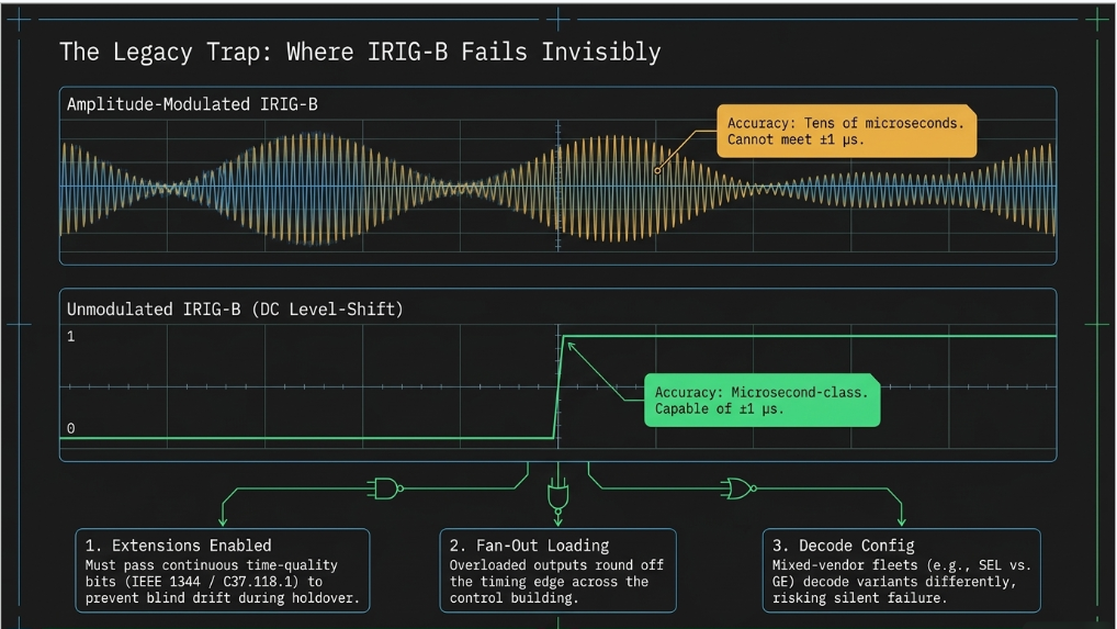
IRIG-B is the workhorse of substation timing: a once-per-second time code distributed from a GPS-disciplined station clock over copper to every relay, recorder, and controller. Most utility-scale solar plants built in the last decade run exactly this architecture a satellite-synchronized clock with a handful of IRIG-B outputs fanned out across the control building. The architecture is sound. Whether it achieves microsecond-class accuracy at each end device depends on implementation details that never appear on a one-line diagram:
- Modulated vs. unmodulated. IRIG-B comes in two flavors. Amplitude-modulated IRIG-B rides on a 1 kHz carrier and is inherently limited to roughly tens of microseconds at best it cannot meet a ±1 µs expectation, full stop. Unmodulated (DC level-shift) IRIG-B delivers a sharp digital edge each second and can achieve microsecond-class accuracy when properly engineered. The first question in any timing verification is simply: which type feeds each recording device?
- The extensions — IEEE 1344 / C37.118.1. The base IRIG-B frame carries day-of-year and time-of-day, and nothing else. The IEEE 1344 extension (carried forward in C37.118.1) adds the year, leap-second and daylight-saving flags, local time offset, and critically continuous time-quality bits that tell every downstream device how good the clock's time actually is at this moment. Without the extension enabled end-to-end, a device keeps stamping records with full confidence even while the clock is drifting in holdover. This is precisely the “additional implementation beyond standard IRIG-B” the IEEE 2800 caveat is talking about.
- Fan-out loading and distribution. A station clock's output can drive only so many device inputs. Every added burden rounds off the timing edge; an overloaded output degrades every device on that run. The verification arithmetic total device burden per output against the clock's drive specification takes minutes and is almost never on file.
- End-device decode configuration. Each relay and recorder must be configured for the IRIG variant actually delivered modulated vs. unmodulated input, extension enabled, correct local-offset handling. A mixed-vendor fleet (protective relays from one manufacturer, recorders from another, plus a PDC) multiplies the chances that one device quietly decodes differently from its neighbors.
- Holdover and failure behavior.
What happens when the antenna fails or GPS is lost? The clock free-runs on its internal oscillator and drifts. The questions that matter: is the clock's alarm contact wired to a monitored point, do downstream devices see the degraded time-quality flags, and do the records they produce during holdover carry that degradation visibly?
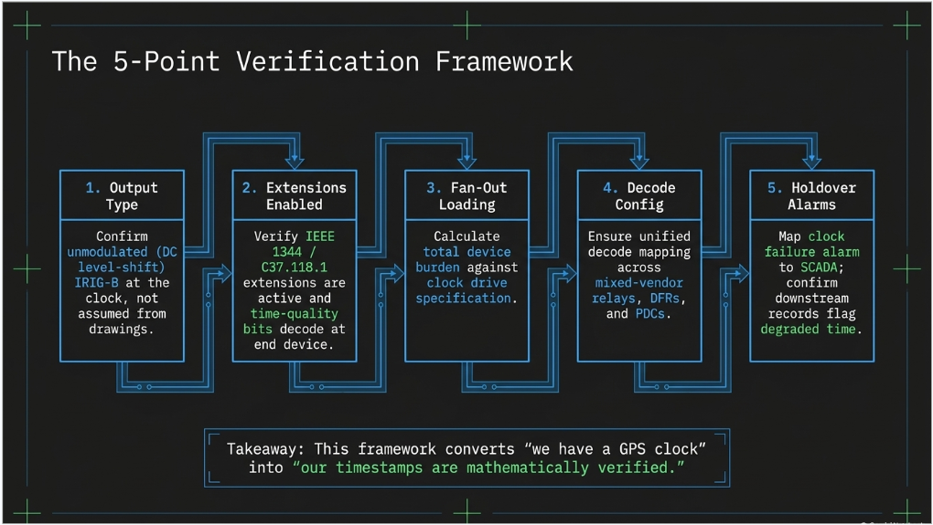
4. The Five-Point IRIG-B Verification
Our engineers apply a structured five-point verification whenever a facility's disturbance-monitoring compliance rests on IRIG-B timing. It converts the abstract ±1 µs question into five concrete, closeable checks:
| # | Check | What passes |
|---|---|---|
| 1 | Output type to the recorders | The clock outputs serving the DFRs, PDC and relays are unmodulated (DC level-shift) IRIG-B — not the modulated variant — confirmed from clock configuration and wiring, not assumption |
| 2 | Extension enabled end-to-end | IEEE 1344 / C37.118.1 extension active at the clock and decoded at every recording device, with continuous time-quality bits carried through — verified in device settings and observed in actual records |
| 3 | Fan-out loading | Total device burden on each clock output is within the drive specification, with distribution runs documented; cable propagation delay accounted for (and shown negligible) inside the control enclosure |
| 4 | End-device decode configuration | Every recorder, relay and concentrator is configured for the delivered IRIG variant, correct UTC/local handling, and consistent decode across the mixed-vendor fleet |
| 5 | Holdover and alarming | Clock failure alarm wired to a monitored annunciator/SCADA point; holdover drift characterized; downstream devices demonstrably flag degraded time quality in the records they produce |
The output of the verification is not a shrug it is evidence: a short engineering record, filed with the compliance documentation, that states what was checked, what was found, and what the demonstrated end-device accuracy class is. That single document converts “we have a GPS clock” into “our timestamps are verified,” which is the difference an audit notices.
5. When IRIG-B Falls Short: The PTP Path
When the verification finds modulated distribution, missing extensions, or an unfixable loading problem, the remediation is rarely a rebuild. Most plants of the last decade already run managed substation Ethernet switches and that network is exactly what IEEE 1588 Precision Time Protocol needs.
Migrating plant-level monitoring to PTP with the IEEE C37.238 power-utility profile (or IEC/IEEE 61850-9-3) delivers sub-microsecond synchronization over the existing LAN, aligns the facility with IEEE 2800's preferred architecture, and is typically a configuration-and-firmware-class project: a PTP-capable grandmaster (often the existing clock family, upgraded), PTP enablement on the existing managed switches, and profile configuration at the end devices. The recorders, relays, and network switches installed at most modern solar plants are already PTP-capable or firmware-upgradeable. In other words: even the worst realistic finding from a timing verification leads to a modest, well-trodden upgrade not new iron.
6. What the Evidence File Should Contain
- The clock's as-left configuration export and antenna installation record
- The five-point verification record, including the observed time-quality behavior
- A timestamp cross-check: the same event (natural or test-triggered) retrieved from the DFR, a relay, and the SOE record, with the measured inter-device offsets stated
- The clock-failure alarm path, shown wired and monitored (annunciator input, SCADA point, notification recipient)
- A periodic re-verification cadence in the facility's disturbance-monitoring operating procedure, aligned to the regional verification requirement
7. Three Case Studies from Recent Assessments (Anonymized)
Case Study 1 — Large ERCOT solar facility: superb hardware, unproven time
A utility-scale solar facility in ERCOT (300+ MW class) presented one of the strongest disturbance-monitoring installations we have assessed: two dedicated digital fault recorders, cross-triggered to one another, with purpose-built isolation modules on the interconnection, both main transformers including neutrals, both collector buses, and every feeder breaker; automated relay event collection; a station phasor data concentrator; and a satellite-synchronized clock distributing IRIG-B station-wide. Our hardware assessment concluded no procurement was required a genuinely complete installation. Yet the timing story could not be closed from the record: the drawings proved IRIG-B reached every device, but nothing on file established the distribution type on the recorder runs, the extension configuration, or a single timestamp cross-check. The five-point verification was written into the compliance plan as a gating item for the configuration phase an afternoon of engineering that converts a first-class installation into a provable one.
Case Study 2 — 200 MW-class facility, mid-2010s-to-2020 vintage: strong bones, aging access
A 200+ MW solar facility commissioned around the turn of the decade carried the same dual-recorder architecture two dedicated DFRs fed by thirteen isolation modules spanning every protection zone plus a station PDC and a GPS clock whose failure alarm was properly wired to a supervised annunciator, alongside health alarms for every communications device. Impressive discipline for its vintage. Two timing-relevant findings emerged. First, the recorders' remote access provisions dated from the design era: dial-up modems alongside Ethernet ports, with no documented central retrieval so even perfectly synchronized records might not reach an analyst inside the regional delivery window. Second, as at the first site, the IRIG-B implementation details (distribution type, extensions, loading) existed nowhere in the record. Both items entered the gap register with the same five-point verification prescribed, and the PTP-over-existing-switches path documented as the fallback explicitly noting that the site's managed substation switches make that a configuration project, not a construction project.
Case Study 3 — Solar facility outside ERCOT: no recorder, but time done right
A 300 MW-class facility in a different interconnection illustrated the inverse pattern. The site had no dedicated fault recorder at all its recording methodology, confirmed in writing during our assessment, relied on protective-relay event reports and SER collected through the station automation system. That architecture carries its own limitations (relay-native records are short and low-sample-rate relative to dedicated-recorder expectations), and it anchored the site's remediation plan. But the timing layer was, refreshingly, demonstrable: relay settings showed IRIG-B with the C37.118 extension enabled fleet-wide, and actual event records retrieved during the review displayed a hardware-IRIG time source with healthy time-quality indications live proof, from the records themselves, that the timestamps could be trusted. The lesson cuts both ways: recording hardware without verified time is unusable evidence, and verified time without adequate recording hardware is an empty stage. Compliance needs both.
8. Frequently Asked Questions
Q: What is IRIG-B, in plain terms?
A time code, born in the 1950s rocket-range world, that a GPS-disciplined station clock sends over copper wire to every relay and recorder once per second. Each device locks its internal clock to it. It remains the most common substation timing method in North America.
Q: What accuracy does plain IRIG-B actually deliver?
It depends entirely on the variant. Amplitude-modulated IRIG-B is limited to roughly tens of microseconds at best. Unmodulated (DC level-shift) IRIG-B, properly engineered with the IEEE 1344/C37.118.1 extension, can deliver microsecond-class accuracy at the end device. Two installations can look identical on a drawing and differ by three orders of magnitude in practice.
Q: Where does the ±1 µs number come from?
IEEE 2800-2022 Clause 11: all plant-level monitoring devices (SER, DFR, DDR, power-quality meters) shall synchronize to UTC within ±1 µs, preferably via IEEE 1588 PTP with a utility profile. Inverter-level devices get ±100 µs. The clause explicitly cautions that plain IRIG-B needs implementation beyond the standard signal to reach the plant-level number.
Q: Does IEEE 2800 apply to my plant, which was commissioned years ago?
Generally not retroactively — it binds where an interconnection agreement or regional requirement adopts it, typically for new resources. But the binding requirements you do carry (the NERC disturbance-monitoring standard and, in ERCOT, the DME requirements with GPS-disciplined timing) point the same direction, and 2800 is the benchmark utilities and auditors reference. Verify against what binds; benchmark against 2800; never claim the benchmark is law.
Q: What does ERCOT specifically require for timing?
The ERCOT DME requirements call for GPS-disciplined time synchronization of the fault-recording equipment, alongside rolling retention, defined delivery windows, and periodic verification of recording functionality with notification of failures. Timing is treated as an inherent property of compliant DME, not an accessory.
Q: What are the IEEE 1344 / C37.118.1 extensions, and why do the time-quality bits matter?
They add year, leap-second, local-offset, and continuous time-quality information to the base IRIG-B frame. The time-quality bits are the difference between a device knowing the clock has degraded (and flagging its records accordingly) and a device stamping confidently wrong times during a GPS outage. Auditable timing is impossible without them.
Q: What is PTP / IEEE 1588, and do I need new hardware for it?
Precision Time Protocol distributes time over the Ethernet network itself, with switches compensating their own delays; with the C37.238 or 61850-9-3 utility profiles it reliably achieves sub-microsecond accuracy. Most plants built in the last decade already own PTP-capable or firmware-upgradeable managed switches, relays, and recorders — migration is usually configuration and firmware, plus a PTP grandmaster, not a rebuild.
Q: How do you actually test timestamp accuracy in the field?
The practical method: trigger (or wait for) one event, retrieve it from the DFR, a relay, and the SOE record, and measure the inter-device offsets on the common signal edges. Combine that with the clock's own accuracy specification and the five-point configuration verification, and you have a defensible demonstrated-accuracy statement without laboratory equipment.
Q: What happens when GPS is lost?
The clock free-runs on its internal oscillator (“holdover”) and drifts at a rate set by oscillator quality. A compliant installation alarms the failure to a monitored point, and downstream devices display degraded time quality in their records. Verification includes confirming both behaviors — discovery during an actual event is the expensive way to learn.
Q: Our plant has a quality GPS clock. Doesn't that settle it?
The clock is necessary, not sufficient. A modern satellite-synchronized clock is accurate to around a hundred nanoseconds at its output terminals — the compliance question lives in everything between those terminals and each recorder: distribution type, extensions, loading, decode configuration, and failure behavior. That is precisely what the five-point verification examines.
Q: Does a mixed-vendor fleet (different relay and recorder manufacturers) change anything?
It raises the value of verification. Different vendors default to different IRIG input modes and offset handling; a fleet can be individually healthy and collectively inconsistent. The cross-device timestamp check is the single test that catches this class of problem.
Q: How often should timing be re-verified?
Fold a timestamp cross-check into the periodic disturbance-monitoring verification your regional requirements already demand (in ERCOT, a recurring verification cadence with failure notification), and re-run the full five-point check after any clock, firmware, or network change. Codify both in the facility's operating procedure.
Q: What does this cost to fix if we find problems?
Almost always less than feared. The common findings — wrong output type, extension disabled, unmonitored clock alarm — are settings and wiring corrections. The worst realistic case, a PTP migration, is a modest configuration-class project over the network you already own. The expensive scenario is the unverified one: an event happens, the records disagree, and the facility cannot produce usable evidence.
9. How Keentel Engineering Can Help
Keentel Engineering performs disturbance-monitoring compliance assessments for utility-scale solar, wind, and storage facilities across North American markets hardware and channel-coverage assessments, configuration and settings verification (including the five-point timing verification described here), gap registers and remediation design, operating procedures, and audit-ready evidence packages. Our engineers work fluently across the platforms this article describes: dedicated digital fault recorders, SEL and GE protection fleets, RTAC-based automation, phasor data concentrators, and plant historians. If your facility's timing story ends at “we have a GPS clock,” we can take it the rest of the way to “verified, documented, and defensible.”

About the Author:
Sandip "Sonny" R. Patel, P.E.
IEEE Senior Member · Founder & CEO, Keentel Engineering
In 1995, Sonny Patel earned his Electrical Engineering degree from the University of Illinois. But degrees don't build legacies — action does.
For three decades, he has worked the power industry from every side of the table: 16 years as a utility engineer at Exelon/Commonwealth Edison; generation leadership across hydroelectric, industrial steam turbine, and a 9 GW renewable fleet; NERC Regional Entity Senior Compliance Engineer and Audit Team Lead, auditing some of the nation's largest utilities; and testing and commissioning lead on equipment up to 765 kV — the very top of the North American grid.Utility. Generator. Regulator. Consultant. Few engineers have seen all four seats. Fewer still have sat in them.
His experience spans nuclear, hydro, conventional generation, renewables, oil and gas, mining — and today's data centers, where he is authoring a three-book series on data center design. He is a Licensed Professional Engineer in six states and a Licensed Electrical Contractor in Florida (Unlimited EC) — he doesn't just design the work; he's qualified to stand behind its execution.Today, as Founder and CEO of Keentel Engineering, Sonny leads a nationwide team of engineers delivering substation design, power system studies, NERC compliance, and commissioning — done right, coast to coast.Three decades. Every side of the table. One standard: accountable engineering.
Services

Let's Discuss Your Project
Let's book a call to discuss your electrical engineering project that we can help you with.
About the Author:
Sandip "Sonny" R. Patel, P.E.
IEEE Senior Member · Founder & CEO, Keentel Engineering
In 1995, Sonny Patel earned his Electrical Engineering degree from the University of Illinois. But degrees don't build legacies — action does.
For three decades, he has worked the power industry from every side of the table: 16 years as a utility engineer at Exelon/Commonwealth Edison; generation leadership across hydroelectric, industrial steam turbine, and a 9 GW renewable fleet; NERC Regional Entity Senior Compliance Engineer and Audit Team Lead, auditing some of the nation's largest utilities; and testing and commissioning lead on equipment up to 765 kV — the very top of the North American grid.
Utility. Generator. Regulator. Consultant. Few engineers have seen all four seats. Fewer still have sat in them.
His experience spans nuclear, hydro, conventional generation, renewables, oil and gas, mining — and today's data centers, where he is authoring a three-book series on data center design. He is a Licensed Professional Engineer in six states and a Licensed Electrical Contractor in Florida (Unlimited EC) — he doesn't just design the work; he's qualified to stand behind its execution.
Today, as Founder and CEO of Keentel Engineering, Sonny leads a nationwide team of engineers delivering substation design, power system studies, NERC compliance, and commissioning — done right, coast to coast.Three decades. Every side of the table. One standard: accountable engineering.
Leave a Comment
Thank you for contacting us.
We will get back to you as soon as possible.
We will get back to you as soon as possible.
Oops, there was an error sending your message.
Please try again later.
Please try again later.
Related Posts
By SANDIP R PATEL
•
October 23, 2026
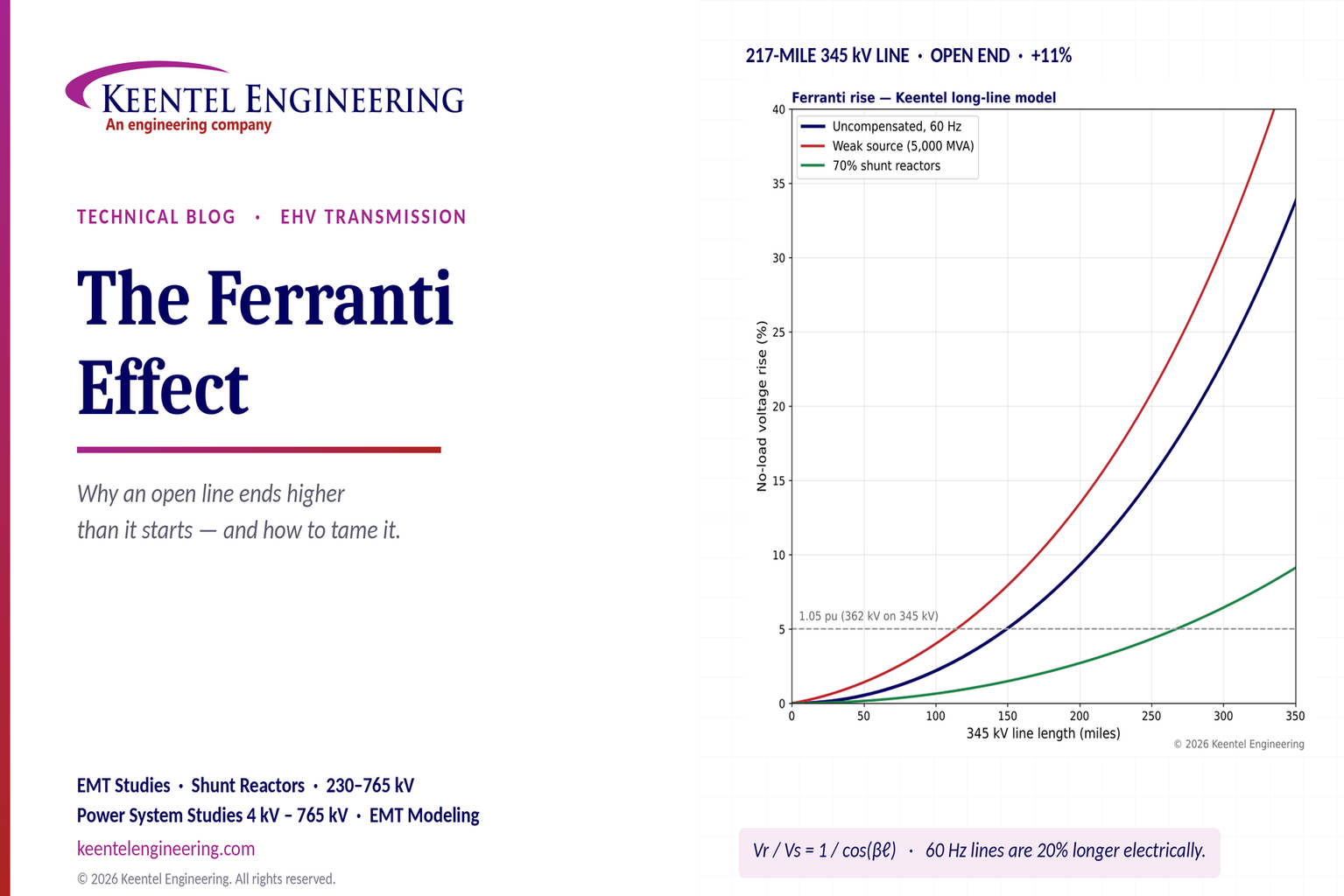
Explore the Ferranti effect in EHV transmission lines: voltage rise, 345 kV examples, switching overvoltages, shunt reactor sizing and mitigation.
By SANDIP R PATEL
•
October 21, 2026
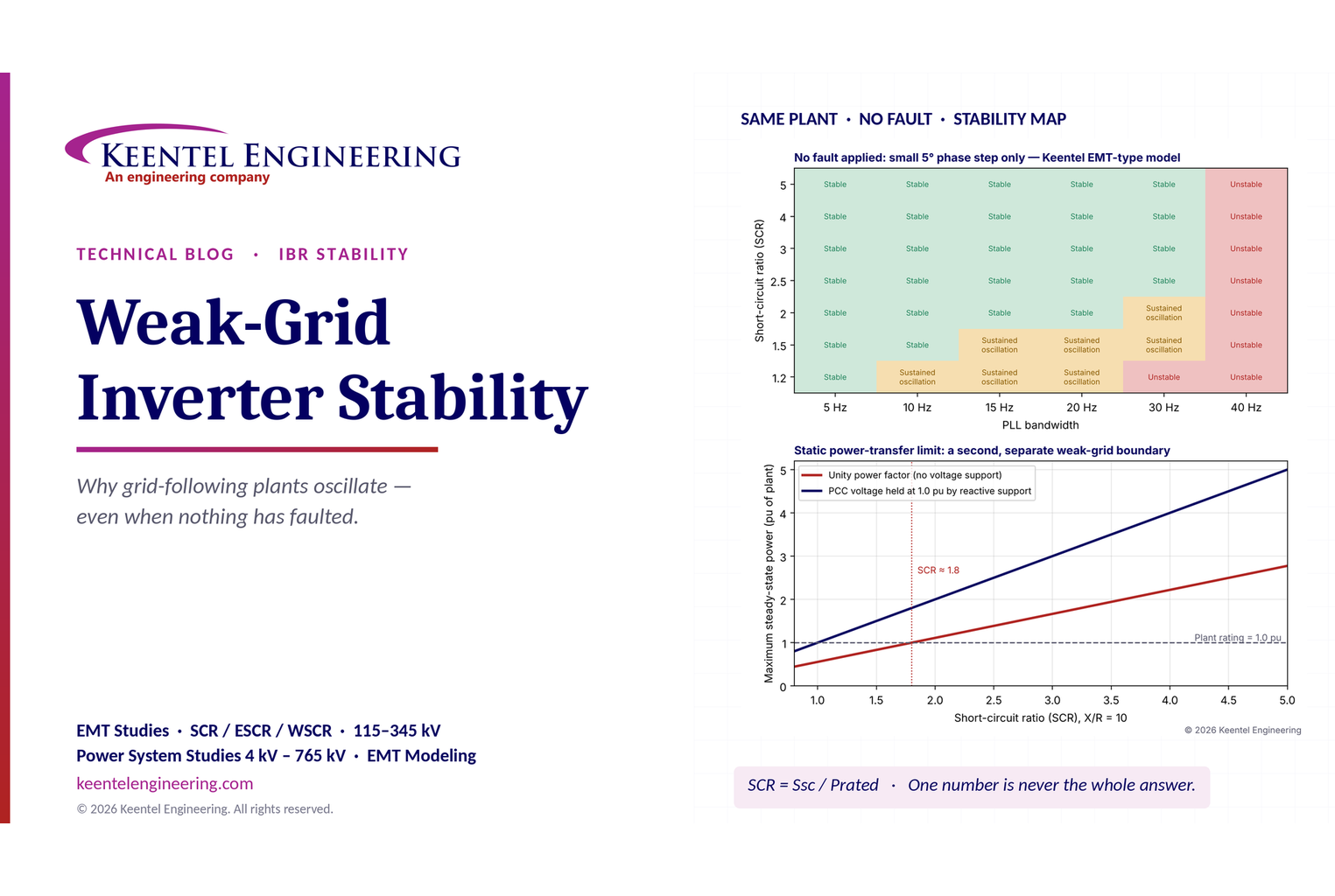
Learn why grid-following inverters become unstable without grid faults. Explore SCR, PLL interactions, EMT studies, grid strength, and mitigation.
By SANDIP R PATEL
•
October 21, 2026
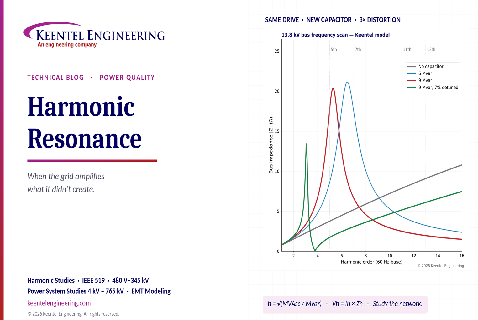
Learn how harmonic resonance amplifies distortion in power systems. Explore capacitor banks, detuned reactors, frequency scans, and IEEE 519 solutions.
By SANDIP R PATEL
•
October 20, 2026
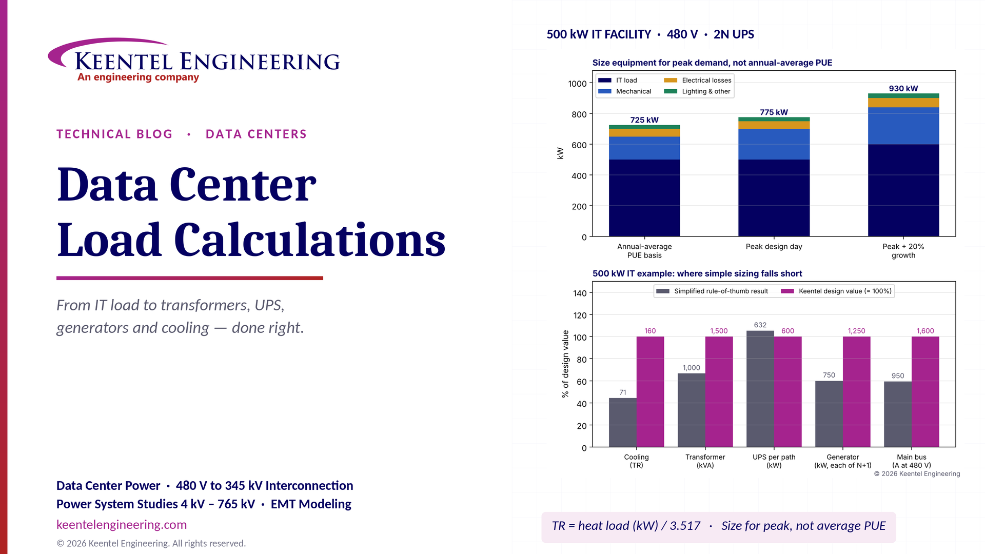
Learn data center electrical load calculations, including IT demand, PUE, UPS and generator sizing, cooling loads, redundancy, and worked US examples.
By SANDIP R PATEL
•
October 20, 2026
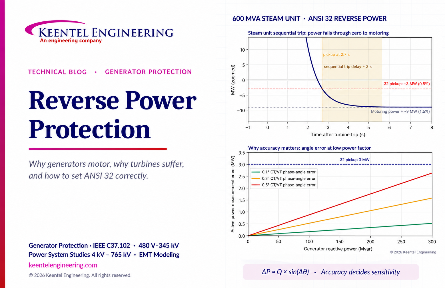
Learn reverse power protection (ANSI 32), generator motoring, relay pickup settings, time delays, sequential tripping and testing for US power plants.
Copy

By Team 2 Dexora
•
October 20, 2026
Explore grounding system testing with Keentel Engineering. Learn IEEE 80/81 methods, soil resistivity, ground resistance, and touch and step voltage safety.

By SANDIP R PATEL
•
October 13, 2026
Plan data center capacity with land screening, MW-per-acre estimates, grid power availability and interconnection feasibility studies from Keentel Engineering.

By SANDIP R PATEL
•
October 11, 2026
Learn which fault produces the highest current at a bus, why SLG faults can exceed three-phase faults, and how symmetrical components determine fault duty.

By SANDIP R PATEL
•
October 11, 2026
Learn why zero-sequence current pulsates in the dq0 frame, how Park's transformation works, and how inverter controls handle unbalance and ground faults.





