
A Coordinated Electric System Interconnection Review—the utility’s deep-dive on technical and cost impacts of your project.
Challenge: Frequent false tripping using conventional electromechanical relays
Solution: SEL-487E integration with multi-terminal differential protection and dynamic inrush restraint
Result: 90% reduction in false trips, saving over $250,000 in downtime
The three operating regions you have to design to
| Device | Output vs voltage | Response | Best suited to | Main limitations |
|---|---|---|---|---|
| Mechanically switched capacitor or reactor | Proportional to voltage squared | Seconds; discrete steps; limited switching operations per day | Steady-state reactive supply, voltage profile, loss reduction | No dynamic capability; step voltage change on switching; capability collapses when most needed |
| Static var compensator | Capacitive branches proportional to voltage squared | A few cycles; continuously controllable | Continuous control where cost matters and deep voltage support is not the driver | Square-law capability loss; harmonic filters are part of the plant and interact with the network |
| STATCOM | Approximately proportional to voltage — constant current capability | One to two cycles closed loop; converter response faster still | Voltage stability margin, weak interconnections, fast disturbance recovery, flicker and unbalance compensation | Higher capital cost; converter losses; adds a converter and its control dynamics to the network |
| Synchronous condenser | Governed by machine capability and excitation | Excitation response in the hundreds of milliseconds; inherent inertial response instantaneous | System strength and inertia, short-circuit contribution, black start support | Rotating plant with maintenance and losses; slower controlled response than a converter |
| STATCOM with energy storage | Reactive as a STATCOM, plus real power within the storage rating | As STATCOM for reactive; real power limited by storage | Where a real power deficiency is part of the problem | Cost and complexity of the storage; different failure and maintenance profile |
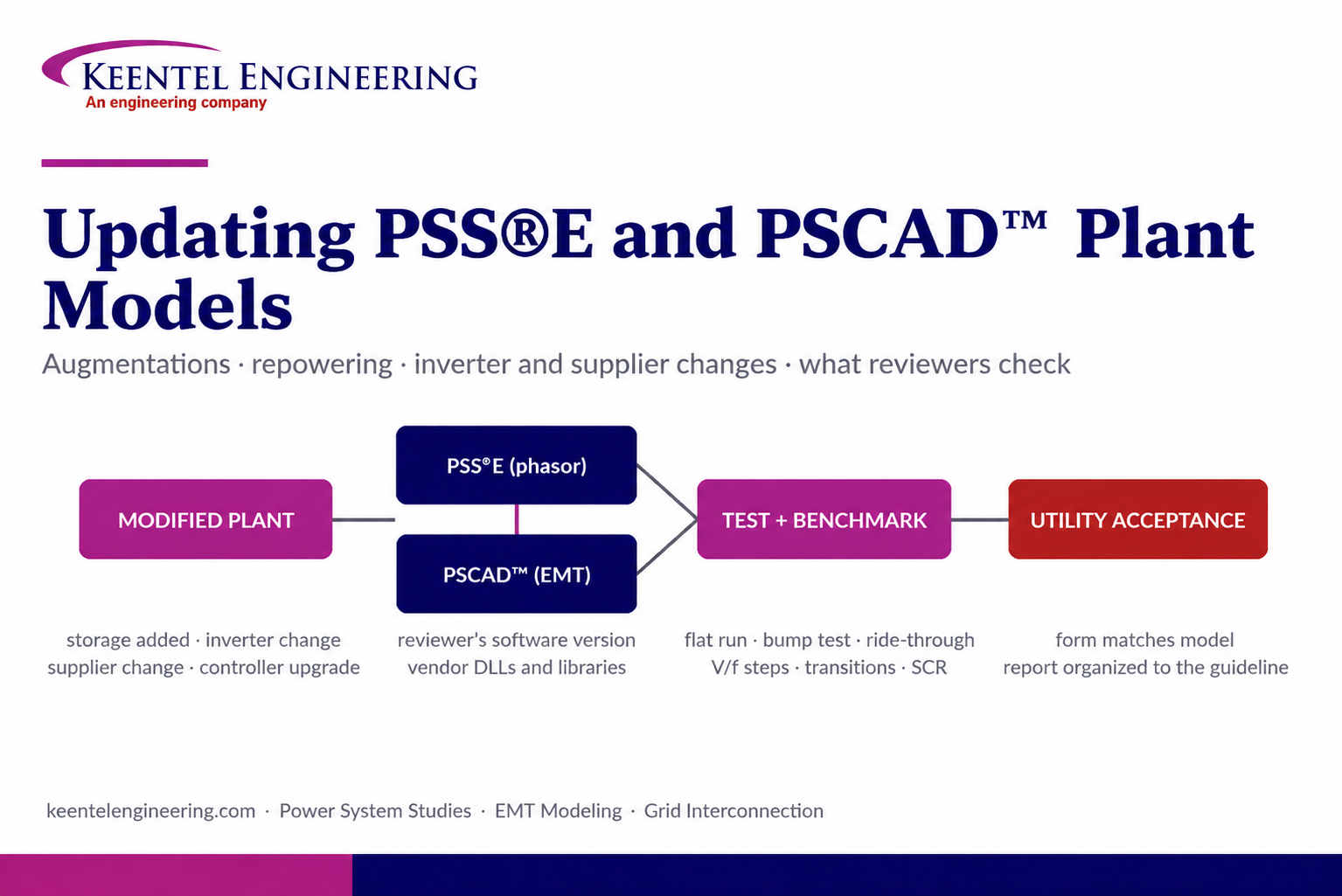
Updating PSS®E and PSCAD™ Plant Models for Augmentations, Repowering and Equipment Changes
September 22, 2026 | Blog
How a model update is scoped, built, tested and accepted, and how Keentel Engineering supports owners through it
Executive Summary
Every inverter-based plant that has been through interconnection carries a pair of models with it: a positive-sequence PSS®E model used by the transmission operator for planning and stability studies, and an electromagnetic-transient PSCAD™ model used where the positive-sequence tools cannot see the physics. Those models were accepted once, on the plant as designed. The plant does not stay that way. Storage is added, inverters are replaced by a newer series, a plant controller is upgraded, a collector is reconfigured, a supplier changes between application and procurement. Each of those events makes the accepted models wrong, and each triggers a model update before the change can be studied, energized or, in many jurisdictions, even scheduled.
A model update is smaller than a new interconnection study, but it is not small. Done well, it is a disciplined engineering task with its own data reconciliation, its own test set and its own acceptance criteria. Done badly, it is the single most common reason a modification sits in a utility queue for an extra review cycle: a model that initializes but does not hold the point-of-interconnection limit through a transition, a PSCAD™ model that will not compile in the reviewer's environment, a plant controller that dispatches inverters the model no longer contains.
This paper explains how Keentel Engineering approaches a model update from first contact to acceptance: what triggers one, what the reviewer will actually check, how the PSS®E and PSCAD™ sides differ, where the effort really goes, and what an owner can do before authorization to shorten the schedule. It closes with three composite case studies drawn from the patterns we see repeatedly, a detailed FAQ, and a description of the services Keentel provides. No specific client, site, project, supplier or utility is described anywhere in this document.
The three things that decide whether a model update is accepted first time
1. The plant controller logic is modeled explicitly, and it behaves the same way in PSS®E and PSCAD™ through every transition the plant can actually make.
2. The model runs in the reviewer's software version and compiler without the reviewer having to ask for anything.
3. The data in the model, the interconnection forms and the drawings agree with each other, because the reviewer checks one against the other.
1. What Triggers a Model Update
A model update is required whenever the as-modeled plant no longer represents the plant that will operate. The common triggers, in rough order of how often we see them, are:
| Trigger | What Changes in the Model | Typical Reviewer Position |
|---|---|---|
| Storage augmentation or addition to an existing PV or wind plant | New aggregated generator(s), pad-mount and collector equivalents, new switchgear bus, plant controller now dispatching multiple resource types, charging cases | Model update at minimum; a revised study if the export or import limit at the POI changes |
| Inverter series change (same manufacturer, newer generation) | Replacement of the inverter dynamic model and parameters in both platforms; ride-through and current-limit settings; possible controller compatibility check | Model update; usually no new study if ratings and POI limits are unchanged |
| Inverter or storage supplier change between application and procurement | Replacement of vendor models in both platforms; re-derivation of the collector equivalent if the block layout changes | Model update; the utility compares the new model's response against the accepted one |
| Plant controller replacement or firmware change affecting control modes | Plant-level controller model and parameters; volt/var, frequency response, ramp and curtailment logic | Model update, often with a targeted re-run of voltage and frequency response tests |
| Protection or ride-through setting change | VTGTPAT/FRQTPAT relay models and inverter protection blocks; PSCAD™ protection logic | Model update with ride-through demonstration; increasingly linked to ride-through standards |
| Collector or transformer change (connection, impedance, second LV main) | Winding configuration, zero-sequence data, equivalent impedances, bus topology | Model update; short-circuit data update |
| Utility software version change | Migration of the case, dynamics and libraries to the new version; recompilation of user-written models | Required before the utility can use the model at all |
| Periodic validation (MOD-026/MOD-027 in NERC regions; equivalent local rules elsewhere) | Parameter validation against test or disturbance data; documentation | Validation report and updated models on the utility's cycle |
Two points follow from the table. First, "model update only" is a scope the utility defines, not the owner: the request form or the modeling guideline says what must be delivered, and that list nearly always includes tests and a report, not just files. Second, a modification that changes the maximum export or import at the point of interconnection is in a different category. Even when the utility calls it an update, it will re-run its own study on the new model, and the model must therefore be good enough to carry that study.
2. Why Two Platforms, and What Each One Is For
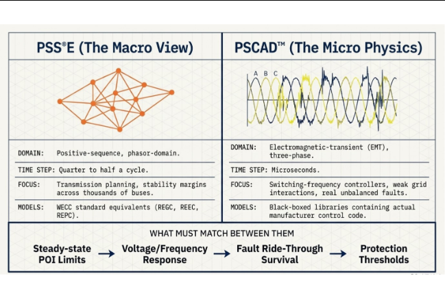
PSS®E and PSCAD™ answer different questions, and a model update has to keep both answers consistent.
2.1 PSS®E: positive-sequence, phasor-domain
PSS®E represents the network as balanced positive-sequence phasors and integrates the dynamics of generators, controllers and loads with time steps of a quarter to half a cycle. It is the tool the transmission planner uses for the interconnected system: thousands of buses, hundreds of contingencies, and stability margins across a region. For an inverter-based plant it uses the second-generation renewable energy models developed under WECC and now standard in every North American planning tool: REGC (the generator/converter), REEC (the electrical control), REPC (the plant controller), and the associated auxiliary and protection models. Some manufacturers supply user-written versions of these models compiled into a DLL, with parameters exposed through the same data file, so that their specific control behavior is preserved.
The plant model in PSS®E is an equivalent: one or a few aggregated generators at the inverter terminal voltage, an equivalent pad-mount transformer, an equivalent collector impedance derived by the WECC method from the actual cable schedule, the main transformer, and the gen-tie to the point of interconnection. The collector equivalent is not a shortcut; it is the accepted way to reproduce the losses and the voltage profile of the real collector at the POI, and it has to be re-derived when the collector changes.
2.2 PSCAD™: electromagnetic-transient, three-phase
PSCAD™ solves the three-phase network in the time domain at time steps of microseconds. It sees what the phasor tool cannot: the inverter's switching-frequency current controller, phase-locked-loop behavior during a fault, negative-sequence current injection, control interaction between inverters and between the plant and a weak grid, and the actual response to unbalanced faults. Manufacturers supply PSCAD™ models as compiled, black-boxed libraries that contain the real control code, which is why a PSCAD™ model is the reference against which the PSS®E model is benchmarked.
The PSCAD™ plant model is also an equivalent, but it usually preserves more structure: separate blocks for each inverter type, explicit pad-mount transformer winding connections and grounding, a collector equivalent per block, and a plant controller model exchanging setpoints with the inverter blocks over a simulated communication delay.
2.3 What has to match
| Quantity | Where It Is Checked | What "Match" Means |
|---|---|---|
| Steady-state P, Q and voltage at the POI for each dispatch | Flat run in both platforms | Same operating point within the tolerance the reviewer states, typically 1% or better |
| Active and reactive response to voltage steps at the POI | Voltage step tests | Same final value; same direction and comparable settling; EMT may show transients the phasor model cannot |
| Response to frequency deviation | Frequency step or ramp tests | Same droop, deadband and final active power; comparable timing |
| Fault ride-through behavior | Balanced fault at the POI in both; unbalanced in EMT only | Neither trips where the other rides through; post-fault recovery comparable; reactive current support consistent with settings |
| Plant controller transitions | Dispatch change, charge/discharge reversal, resource switch | POI limit held in both; no unintended trip; ramp consistent |
| Protection | Relay models in PSS®E; protection blocks in PSCAD™ | Same thresholds and timers, both pointed at the same monitored bus |
3. The Model Update Process, Step by Step
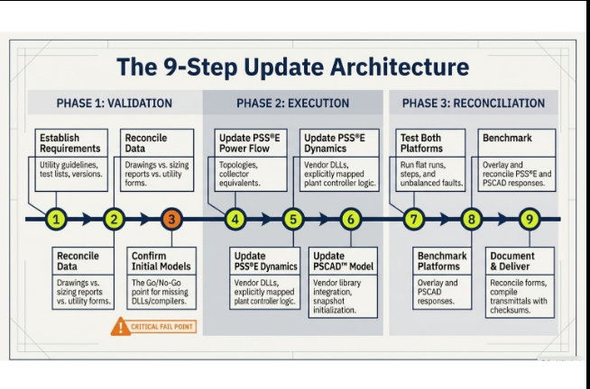
Keentel runs a model update as nine steps. The order matters: the steps that surface problems are early, so that a problem changes the plan rather than the schedule.
Step 1 — Establish what the reviewer will check
Before opening a model file, obtain the utility's current requirements: the information request form, the modeling guideline, the required software versions, the list of accepted generic models, the required tests and their acceptance criteria, and the format of the compliance report. These change. A form that required a particular version two years ago may require a newer one today, and a guideline may now list tests that the original study did not include. Everything downstream is sized against this list.
Step 2 — Reconcile the data
Collect the request email, the drawings, the previous study report, the previous submission forms, the vendor sizing reports and the vendor datasheets, and compare them. They never agree. Inverter counts differ between the drawing and the sizing report; the transformer connection on the form differs from the model; the storage energy on the email is the usable figure and on the datasheet the installed figure. Each disagreement is listed with the value in each source and the value the model will use, and that list is confirmed with the owner at kickoff. This step is cheap and it prevents the most expensive kind of review comment: "your form says X and your model says Y."
Step 3 — Confirm the existing models run
Open the accepted PSS®E case and dynamics file in the version the utility now requires; obtain and load the manufacturer DLLs; run a flat start. Open the PSCAD™ workspace in the version the vendor libraries are compiled for, with the matching compiler; run to steady state from the snapshot. A model that ran in the original consultant's environment may not run in yours or the reviewer's: missing DLLs, a compiler mismatch, a library compiled for a different PSCAD™ release, or a snapshot file that was never delivered. This is the go/no-go point. If the models must be rebuilt rather than updated, the owner should know in the first week, not the fourth.
Step 4 — Update the PSS®E power flow
- Add new aggregated generators with the correct MVA base, terminal voltage and capability limits from the vendor data at the design ambient temperature.
- Add equivalent pad-mount transformers with the correct winding connection, impedance and tap, and re-derive the collector equivalent from the new cable schedule using the WECC method.
- Add new switchgear buses, tie breakers and the connection to the main transformer bus; confirm the main transformer impedance and tap data against the nameplate, not the previous form.
- Build the dispatch cases the tests need: each resource alone, resources combined, charging (from on-site generation and from the grid, up to the permitted import), and any partial-availability case the utility asks for.
- Verify the reactive capability at the POI for each case against the utility's power-factor requirement, including the reactive consumption of the transformers and collector.
Step 5 — Update the PSS®E dynamics
- Replace or add the inverter models: vendor DLL models where accepted, otherwise the generic REGC/REEC set with parameters matched to the vendor's settings, including current limits, priority (real or reactive), ride-through thresholds and reactive current gain.
- Configure the plant controller: the REPC or vendor plant-level model, with the POI as the regulated bus, and the logic that governs multiple resource types, mutual exclusion where it exists, the export and import limits, dispatch priority, frequency droop and deadband, voltage control gains and ramp limits.
- Point every protection model at the monitored bus the utility specifies, usually the POI, and set thresholds and timers from the ride-through requirement.
- Set up the dynamics so that a dispatch change does not require editing the model: which resource is in service should follow from the power-flow case.
Step 6 — Update the PSCAD™ model
- Integrate the vendor's compiled inverter libraries for each inverter type, scaled to the aggregated block ratings the reviewer has accepted.
- Represent the pad-mount transformers with the actual winding connections and grounding, because these set the zero-sequence path and therefore the unbalanced-fault behavior.
- Implement the plant controller with the same logic as the PSS®E model, including the communication delay between controller and inverters, so that the two platforms are tested against the same rules.
- Initialize to steady state for every dispatch case and save snapshots so that each test starts from a clean operating point.
Step 7 — Test
Run the utility's test set on both platforms. The general shape is the same everywhere even when the names differ:
| Test | PSS®E | PSCAD™ | What It Proves |
|---|---|---|---|
| Flat run (no disturbance, 10 to 20 s) | Required | Required | Model is initialized correctly and numerically stable |
| Bump test (three-phase fault at the POI, cleared after a few cycles) | Required | Recommended | Model recovers, no spurious trip, controller re-settles |
| Voltage step at the POI (±2 to ±5%) | Required | Required | Volt/var response, gain, settling time, steady-state error |
| Frequency step or ramp | Required | Required | Droop, deadband, response time, headroom handling |
| Low- and high-voltage ride-through profiles | Required | Required | No trip inside the must-ride-through region; reactive current support |
| Frequency ride-through profiles | Required | Often | No trip inside the frequency envelope |
| Unbalanced faults (SLG, LL, LLG) at the POI | Not applicable | Required | Negative-sequence behavior, PLL stability, phase-selective protection |
| Reduced short-circuit ratio | Sometimes | Required where the POI is weak | Control stability and interaction at low system strength |
| Dispatch and mode transitions | Required for hybrids | Required for hybrids | POI limit held; no trip during resource switch or charge/discharge reversal |
| Power-factor capability sweep | Required | Optional | Reactive range at the POI across the voltage window |
Step 8 — Benchmark PSS®E against PSCAD™
Overlay the two platforms' responses for every common test. The point is not to make the traces identical; the phasor model cannot reproduce the EMT model's sub-cycle behavior and is not supposed to. The point is to confirm that the steady-state values match, that the direction and magnitude of the response match, that neither model trips where the other rides through, and that any remaining difference is explained by something the reviewer will accept: filtering, PLL dynamics, or a protection element that the positive-sequence model cannot represent. A benchmark section with explained differences is what turns a reviewer's question into a footnote.
Step 9 — Document and deliver
The model documentation report describes the plant as modeled, the source of every parameter, the plant controller logic in words and in a block diagram, the case list, the test results with plots, the benchmark comparison, and the software and compiler versions of every delivered file. The data package includes the power-flow case, the dynamics file, the DLLs, the PSCAD™ workspace and libraries, the snapshots, and a one-line of the modeled system. The utility form is reconciled to the model and re-issued alongside it. A transmittal lists file names and checksums so that nobody debates later which version was submitted.
4. Where the Effort Actually Goes
Owners are often surprised that the PSCAD™ side of a model update takes longer than the PSS®E side, and that testing takes as long as building. The distribution below is typical for a storage augmentation to an existing PV plant with an inverter series change, expressed as a share of total engineering hours.
| Activity | Share of Effort | Why |
|---|---|---|
| Data reconciliation and kickoff | 5–8% | Small but decisive; it sets the basis for everything else |
| PSS®E power flow update | 8–10% | Topology, equivalents and cases are mechanical once the data is settled |
| PSS®E dynamics update | 18–22% | Controller logic for a hybrid plant is the largest single item |
| PSCAD™ update | 22–26% | Vendor library integration, initialization, controller implementation, snapshots |
| Testing and benchmarking | 20–25% | The full test set on two platforms, with re-runs after each correction |
| Short-circuit and capability checks | 4–6% | Fault levels and SCR at the POI; reactive range |
| Documentation and form reconciliation | 8–10% | The report is what the reviewer reads first |
| Utility review support | 5–8% | Answers, re-runs, meeting attendance |
Three things move these numbers. A PSCAD™ version migration adds effort in proportion to the number of user components and the age of the original workspace. A plant controller that must coordinate two different manufacturers' storage controllers adds a hierarchy that has to be designed before it can be modeled. And any dispute over which model set the utility accepts (vendor user-written versus generic) can add a full parameterization exercise.
5. The Hybrid Plant Controller: Where Model Updates Are Won or Lost
When storage is added to a generation plant, the reviewer's attention moves from the inverters to the controller that sits above them. The reason is simple: with storage, the plant has more inverter capacity than it is allowed to export, so what appears at the point of interconnection is decided by control logic, not by hardware ratings. A plant with 60 MW of PV, 30 MW of existing storage and 120 MW of new storage behind a 95 MVA transformer and a 60 MW export limit is a controller problem first and a network problem second.
5.1 What the controller model must contain
- The regulated bus (the POI) and the measured quantities the controller acts on.
- The export limit and, where grid charging is permitted, the import limit, and how each is enforced (curtailment order, ramp rate, deadband).
- The dispatch priority between resource types: which resource is curtailed first when the sum exceeds the limit, and which serves the reactive requirement.
- Mutual exclusion or sequencing rules, for example where only one storage bank may discharge at a time, or where charging from generation has priority over export.
- The volt/var or power-factor mode, its gains, and the split of reactive duty among resources.
- Frequency droop, deadband, headroom reservation and the response of a charging resource to under-frequency (which can reverse from charging to discharging).
- Communication and measurement delays, which govern whether a fast disturbance is handled by the inverters' own controls or by the plant controller.
5.2 The transition tests
The tests that expose a weak controller model are the transitions: a dispatch change from export to import; a switch from one storage bank to another; a cloud transient on PV while storage is charging; a frequency event while the plant is curtailed. In each case the reviewer wants to see the POI quantity move smoothly to the new value without exceeding the limit and without any inverter group tripping on a transient it should have ridden through. These tests are not in every utility's standard list, but they are the ones a reviewer runs when the standard tests look too clean.
Modeling the controller as a limit is the most common shortcut, and the most common reason for a second review cycle
A single active-power cap at the POI produces correct steady-state results and incorrect transitions. The reviewer's own study will exercise the transitions. Keentel models the controller as the supervisory system it is, in both platforms, and tests the transitions before the reviewer does.
6. Software Versions, Compilers and Compiled Models
A large share of model-update delays has nothing to do with engineering. It is the mechanics of getting files to run.
6.1 PSS®E
- Utilities specify a version. Cases and dynamics files migrate forward reasonably well, but user-written models are compiled against a specific version and must be re-supplied by the manufacturer for the target version.
- A dynamics file that references a user model without its DLL will not initialize. Obtain the DLL with the model, not after.
- Generic models are version-stable and reviewer-friendly. Where the utility lists the generic set, parameterizing it from the vendor data is often faster than chasing a DLL for the right version, provided the vendor supplies the parameter mapping.
6.2 PSCAD™
- Vendor libraries are compiled for a PSCAD™ release and a Fortran compiler (Intel or GFortran) and will not load in a different combination. Confirm the vendor's supported combinations before the schedule is set.
- A workspace built in an older release opens in a newer one, but user components with custom code may need to be recompiled, and older library components may have been superseded.
- Snapshot files are release-specific. If the original snapshots are unavailable, every test starts with a full initialization run, which is slower but harmless.
- Reviewers run the model in their environment. Delivering the exact release and compiler versions in the transmittal, and a model that initializes from a clean workspace, avoids the first round of comments entirely.
6.3 Model quality checklists
Several utilities and system operators now publish model quality checklists: documentation completeness, accuracy against vendor data, usability (initializes, runs at the stated time step, no manual intervention), and efficiency (runs in reasonable time). A model update should be checked against the applicable list before submission, item by item, and the report should say so.
7. Collector Equivalents, Transformer Connections and Zero Sequence
A modification that adds inverters or changes the transformer connection changes the parts of the model that reviewers check numerically rather than by plot.
7.1 The collector equivalent
The WECC equivalencing method reduces a radial collector of many cable segments and many identical inverter blocks to a single series impedance and shunt susceptance that reproduce the same losses at rated output. It requires the cable schedule (size, length, configuration) and the number of inverters on each segment. When blocks are added, removed or rearranged, the equivalent is re-derived; reusing the old equivalent with a new MVA base is a recognizable error and reviewers recognize it.
7.2 Winding connection and grounding
Inverter step-up transformers are typically delta on the MV side and grounded wye on the LV side, or wye-grounded on both sides with a delta tertiary, and the choice determines whether the collector is a zero-sequence source. Some inverters require a solidly grounded LV circuit; others are designed for delta-connected collection. In PSS®E the connection sets the zero-sequence data used for single-line-to-ground fault levels. In PSCAD™ it sets the unbalanced-fault behavior the reviewer will actually simulate. A model update that adds a resource with a different connection from the existing plant must represent both, not assume one.
7.3 Short-circuit contribution and system strength
Inverter fault contribution is control-limited, typically 1.1 to 1.3 per unit of rated current, and is entered as such in the short-circuit model rather than as a subtransient reactance. Adding inverter capacity raises the plant's contribution modestly but raises its sensitivity to system strength considerably: the short-circuit ratio at the POI falls as inverter MVA rises for the same grid. A model update should report the new SCR and, where it is low, run the reduced-strength EMT tests so the reviewer does not have to ask.
8. What an Owner Can Do Before Authorization
The schedule of a model update is governed by inputs, not by engineering hours. An owner who does the following before issuing a notice to proceed shortens the schedule by weeks.
- Locate the accepted model package: PSS®E case and dynamics file, manufacturer DLLs, PSCAD™ workspace, libraries and snapshots, the study report, and any utility comment record. Confirm the software versions in which each was delivered.
- Obtain the utility's current form, guideline and version requirements, and confirm in writing what the utility has classified the modification as.
- Request the new equipment's PSS®E and PSCAD™ models from each manufacturer immediately. Model release under non-disclosure agreements is the single most common schedule risk, and it cannot be started by the consultant.
- Write down the operating philosophy in a page: export limit, import limit, charging source, dispatch priority, sequencing rules, grid services required by the offtake agreement. The model can only be as definite as this page.
- Settle the equipment counts and ratings, or accept that the model will be built on the application basis and adjusted once.
- Name one technical point of contact who can answer data questions the same day.
9. Composite Case Studies
About these case studies
Each case below is a composite constructed from patterns Keentel has encountered across multiple engagements. None describes a specific client, site, project, manufacturer, utility or regulator, and any resemblance to a particular project is coincidental. Figures are illustrative.
Case A — Storage augmentation behind a fixed export limit
Situation. An operating 60 MW PV plant with a small integrated battery was awarded a contract extension to add two 4-hour storage banks, each rated at the plant's export limit, on a new medium-voltage switchgear lineup connected to the existing main transformer. The utility classified the change as a model update and stated that it would update its own interconnection study from the revised models. The owner needed the submission in three weeks.
What the review found
The accepted PSS®E model was in the version the utility still required and used manufacturer user-written models with a plant-level controller; the DLL had not been delivered with the original package. The PSCAD™ model was several releases old. The concept drawings, the request email, the storage supplier's sizing report and the utility form gave three different inverter counts and two different inverter models for the new banks, and the form showed a main transformer connection and impedance that did not match the accepted model. The form also stated a maximum charging import above the export limit, which the owner had not mentioned.
What was done
Data reconciliation produced a single basis table agreed at kickoff, with the form entries to be corrected listed explicitly. The manufacturer DLL was requested on day one and the new inverter models on day two. The PSS®E model was extended with two aggregated storage blocks, new switchgear bus and tie, and a supervisory controller implementing the export limit, the import limit, one-bank-at-a-time sequencing and PV-first dispatch. The PSCAD™ workspace was migrated to the release the new vendor libraries required and the same controller logic implemented with a measured communication delay. The utility's flat-run and bump tests, ride-through profiles, voltage and frequency steps and power-factor sweep were run on both platforms, plus the transitions: export-to-import reversal, bank switch, and an under-frequency event while charging.
Outcome
The transition tests revealed that the initial controller implementation allowed a two-second overshoot above the export limit during a bank switch. The sequencing logic was corrected to ramp the incoming bank only after the outgoing bank reached zero. The package was submitted with a benchmark section explaining the remaining EMT-versus-phasor differences. The utility's single round of comments concerned documentation only.
Lesson
The form was the specification. Reading it first, rather than the email, defined the test set and surfaced the charging import before it became a review comment.
Case B — Inverter series change with a plant controller that no longer matched
Situation. A wind-plus-storage facility replaced its storage inverters with the manufacturer's next-generation series during a warranty-driven retrofit. Ratings at the POI were unchanged. The owner assumed no model work was needed until the transmission operator's periodic model validation flagged that the dynamics file referenced a model the manufacturer no longer supported in the operator's current software version.
What the review found
The new series used different current-limit logic and a faster reactive-current response during faults, and its ride-through settings had been commissioned to a newer standard than the model reflected. The plant controller model, supplied years earlier, had been tuned for the old inverter response; with the new inverter models installed, the voltage control loop showed a lightly damped oscillation in the PSS®E voltage step test that was not present in PSCAD™.
What was done
The generic second-generation models were parameterized from the manufacturer's data sheet for the new series, because the operator's guideline listed the generic set and the manufacturer's DLL for the required version was months away. The plant controller gains were re-tuned in PSS®E to match the PSCAD™ response, with the tuning documented as a change from the accepted values and justified by the benchmark. Ride-through relay models were reset to the commissioned settings and pointed at the POI. The validation report compared the new model against recorded plant response to a real voltage disturbance from the operator's disturbance monitoring.
Outcome
The operator accepted the generic-model submission and the re-tuned controller. The owner adopted a rule that any inverter firmware or hardware change triggers a model check before the change is commissioned.
Lesson
An unchanged rating is not an unchanged model. Controller tuning that was correct for one inverter generation can be wrong for the next, and the benchmark against EMT is how that is found.
Case C — Supplier change after the application, with two candidate technologies
Situation. A developer filed an interconnection application for a storage addition on the basis of one supplier's equipment, then opened a competitive procurement between that supplier and a second whose product used a different block architecture: two battery units per three-winding medium-voltage transformer, a different LV voltage and connection, and a proprietary site controller under the plant controller. The utility's review clock was already running.
What the review found
The two candidates differed in ways that mattered to the model: block MVA base, LV winding connection and grounding, transformer impedance, fault-current withstand, ride-through and reactive-current settings, and the control hierarchy. Building both in full would have doubled the modeling effort; building neither until award would have missed the review window.
What was done
The model was built on the application basis, with the plant model structured so that the storage block, its transformer and its controller interface were a single replaceable sub-model in each platform. The data reconciliation table carried both candidates side by side. When the second supplier was selected two weeks before submission, the sub-model was swapped, the collector equivalent re-derived for the new block layout, the controller hierarchy adjusted to pass setpoints through the site controller, and the full test set re-run. The utility form was corrected to the selected equipment and re-issued with the models.
Outcome
The swap cost a fraction of a second build. The utility noted the change in a single comment and accepted the corrected form.
Lesson
When the supplier is undecided, the model architecture should make the supplier a component, not a foundation. That is a design decision made at kickoff.
10. How Keentel Engineering Assists
Keentel Engineering's
Power System Studies group supports owners, developers and EPC contractors through every stage of a model update, from the first scoping call to acceptance by the utility or system operator.
| Service | What Keentel Does | What the Owner Receives |
|---|---|---|
| Scoping and classification | Reads the utility's form and guideline, confirms the classification of the modification, defines the test set and the deliverable list, and prices the work as a lump sum with explicit assumptions | A fixed scope and fee before authorization, with the input dates that govern the schedule |
| Data reconciliation | Compares every source (drawings, forms, vendor data, prior studies, emails) and produces a single agreed basis with a list of corrections to make to the utility form | A basis table at kickoff and a marked-up form to resubmit with the models |
| Model condition assessment | Runs the accepted models in the required software and compiler versions, identifies missing DLLs, libraries, snapshots and version conflicts, and states within the first week whether the models can be updated or must be rebuilt | A go/no-go memo before major effort is spent |
| PSS®E update | Power flow topology and equivalents, dynamics with vendor or generic models, plant controller logic, protection models, dispatch cases | Case, dynamics file and libraries in the utility's version |
| PSCAD™ update | Vendor library integration, transformer and grounding representation, plant controller implementation, initialization and snapshots, version migration where required | Workspace, libraries and snapshots that initialize cleanly in a fresh environment |
| Testing and benchmarking | The utility's full test set on both platforms, the transition tests for hybrid plants, reduced-strength EMT tests where the POI is weak, and an overlaid benchmark with explained differences | Plots and tables in the format the reviewer expects, and a benchmark section that pre-empts the usual questions |
| Short-circuit and capability | Fault levels at the collector and POI buses with control-limited inverter contributions, POI short-circuit ratio, reactive range across the voltage window | Numbers for the design team and for the form |
| Documentation | Model documentation and compliance report organized to the utility's form or guideline, with parameter sources, controller block diagrams, case list, results and version transmittal | A package the reviewer can accept without a data request |
| Review support | Responses to technical questions, re-runs, attendance at review meetings alongside the owner | A single technical voice through acceptance |
| Vendor model procurement support | Specifies to each manufacturer exactly which model files, versions and compilers are needed, on the day of authorization | Vendor requests that come back right the first time |
Keentel works in PSS®E, PSCAD™/EMTDC™, PSLF, PowerFactory, ASPEN OneLiner and ETAP, across FERC-jurisdictional and non-jurisdictional systems, and across the requirements of individual transmission operators, ISOs and island utilities. Every deliverable is reviewed by a senior engineer independent of its preparation before release. Keentel's methodologies, scripts and tool configurations are proprietary and are not delivered; the models and reports are the owner's.
11. Frequently Asked Questions
1. Does adding storage to my existing plant always require a model update?
Yes. Storage changes the plant's dynamic behavior even when the export limit is unchanged, because a new resource with its own controls now shares the point of interconnection. Whether it also requires a new or revised interconnection study depends on whether the maximum export or import at the POI changes and on the utility's own rules. Ask the utility for a written classification before scoping the work.
2. What is the difference between a "model update" and a "study"?
A model update delivers revised model files that represent the modified plant, with the tests that prove the files are usable and the plant behaves as required. A study uses those files in the utility's system case to evaluate thermal, voltage, short-circuit and stability impacts on the grid. Many utilities perform the study themselves once the owner delivers an acceptable model; others require the owner's consultant to perform and report it.
3. Why do I need both PSS®E and PSCAD™?
The transmission planner's tools are positive-sequence phasor programs and cannot represent inverter control behavior during faults, unbalanced conditions or weak-grid operation. The EMT model is the reference for that behavior, and the positive-sequence model is benchmarked against it so that the planner's studies are trustworthy. Most transmission operators now require both for inverter-based plants above a size threshold or at weak points of interconnection.
4. Which PSS®E version should the update be in?
The version the utility specifies in its current form or guideline, which is not always the newest release. Migrating forward is straightforward for cases and generic models; manufacturer user-written models must be re-supplied for the target version.
5. My original consultant used the manufacturer's user-written models. The utility's form lists generic models. Which do I submit?
Whichever the utility will accept, and the form is the best evidence of that. Generic models parameterized from the manufacturer's data are version-stable and easy to review; user-written models preserve proprietary behavior. When in doubt, submit the generic set and offer the user-written models as a supplement. Never submit user-written models without the DLL for the required version.
6. What is a flat run and a bump test, and why do reviewers insist on them?
A flat run is a simulation with no disturbance, long enough to show that every state in the model is initialized and nothing drifts. A bump test applies a short fault at the POI and shows that the model recovers to the same operating point without tripping. Together they prove the model is usable before any performance test is run. They are the cheapest tests to run and the ones most often skipped.
7. How long does a model update take?
For a well-documented plant with vendor models in hand, three to five weeks from authorization to a submission-ready package on both platforms. The schedule is governed by inputs: the accepted model files, the vendor models for new equipment, and the owner's operating philosophy. Vendor model release under non-disclosure agreement is the most common cause of delay.
8. What do you need from me to start?
The accepted PSS®E case and dynamics file with any DLLs; the PSCAD™ workspace, libraries and snapshots; the original study report and utility comment record; the utility's current form and guideline; the drawings and datasheets for the modification; and a page describing how the plant will be operated after the change.
9. My inverter supplier changed from the one in the application. How much of the model has to change?
The inverter block in both platforms: the dynamic models and parameters, the ride-through and current-limit settings, the step-up transformer data and connection, and possibly the collector equivalent if the block layout changed. If the model was built with the supplier as a replaceable sub-model, the swap is modest; if not, it is a partial rebuild.
10. The plant will charge from the grid. Does that change the model?
Yes. Charging cases must be built in the power flow at the permitted import, the controller model must implement the import limit, and the dynamic tests should include a reversal from export to import and an under-frequency event during charging, because a storage resource that is charging is expected to reduce or reverse its import in response to low frequency.
11. What is a collector equivalent and why is it re-derived?
It is a single impedance and susceptance that reproduces the losses and voltage drop of the real collector at rated output, derived from the cable schedule by the WECC method. When inverters are added or the collector is rearranged, the losses change and the equivalent must be recomputed. Reusing the old equivalent is a common and visible error.
12. The new equipment has a different LV connection than the existing plant. Does that matter?
It matters in PSCAD™ for unbalanced faults and in PSS®E for zero-sequence short-circuit data. A delta-connected collector and a solidly grounded wye collector present different zero-sequence paths, and a plant that has both must model both.
13. What does the reviewer actually look at first?
The report, then the form, then the flat run. If the report is organized to the utility's form and the form matches the model, the reviewer moves to the results. If the form and the model disagree, the reviewer stops and issues a data request.
14. Why do transition tests matter for a hybrid plant?
Because a hybrid plant's behavior at the POI is decided by the plant controller, and the controller is exercised hardest when the dispatch changes: bank switch, charge-to-discharge reversal, PV cloud transient during charging, frequency event while curtailed. Standard step tests do not exercise these; the utility's own study will.
15. What is the short-circuit ratio and why report it?
The ratio of the grid's short-circuit MVA at the POI to the plant's rated MVA. It is the first-order indicator of whether the inverters will be stable on that grid. Adding inverter capacity lowers it. Below roughly 3, most reviewers expect EMT tests at reduced strength; below 2, expect detailed control interaction screening.
16. Can the update be done without PSCAD™ if the original study did not include EMT?
Only if the utility says so in writing. Requirements have tightened since many plants were first studied, and an augmentation is often the point at which the utility asks for an EMT model for the first time.
17. Can you update a model that another consultant built?
Yes, provided the files exist and run. The model condition assessment in the first week determines whether they can be updated or must be rebuilt. Ownership of the models rests with the owner, not the original consultant, but the manufacturer libraries inside them are subject to the manufacturers' terms.
18. What if the accepted model will not run in the utility's current software version?
Then a version migration is part of the update: cases and generic models migrate directly; user-written models need the manufacturer's version-specific DLL; PSCAD™ libraries need the matching release and compiler. This is assessed in week one so that the owner knows the scope before major effort is spent.
19. What is PSS®E-to-PSCAD™ benchmarking and what counts as a pass?
Overlaying both platforms' responses to the same tests. A pass is matching steady-state values, matching direction and magnitude of response, no trip in one where the other rides through, and remaining differences that are explained by the physics the phasor model cannot represent. Identical traces are neither expected nor achievable.
20. How are ride-through settings handled in the update?
The relay and protection models in both platforms are set to the commissioned inverter settings, pointed at the bus the utility specifies, and tested against the utility's ride-through profiles. Where a newer ride-through standard applies to the modification, the settings are checked against it and any gap is reported to the owner before submission.
21. Do you validate the model against measured plant data?
Where the utility requires it, or where recorded disturbance data is available, yes. Periodic validation programs in NERC regions require comparison against test or event data on a defined cycle; an augmentation is a good time to satisfy that cycle with the updated model.
22. What happens if the utility comes back with comments?
Most comments fall into three groups: documentation, a data mismatch between form and model, or a request for an additional case. A well-prepared package draws the first group only. Keentel's scopes include an allowance for responses and re-runs, and additional cycles caused by a change in the utility's requirements are handled separately.
23. How is the work priced?
As a lump sum against a defined test set and deliverable list, with stated assumptions about the condition of the existing models and the availability of vendor models. Anything that turns out differently is raised before it is worked, not invoiced afterwards.
24. Does the model update cover the protection design for the new switchgear?
No. The update models protection as it affects ride-through and tripping; it does not design relay schemes or settings. Keentel's Protection and Control group provides that separately, and a model update often surfaces issues, such as a transformer differential zone that changes when a second LV main is added, that the design team should see early.
25. What is the single best thing an owner can do to shorten the schedule?
Request the new equipment's PSS®E and PSCAD™ models from the manufacturer on the day the decision to modify is made, and ask for the exact software and compiler versions in the same request. Everything else can be done in parallel; this cannot be started by anyone but the owner.
12. References and Further Reading
The following public documents describe the model structures, test methods and quality criteria discussed in this paper. Links and revisions were current at publication; readers should confirm the version their utility applies.
- WECC Renewable Energy Modeling Task Force — Solar Photovoltaic Power Plant Modeling and Validation Guideline, and the second-generation generic model specifications (REGC, REEC, REPC).
- WECC — Guideline for Equivalencing Collector Systems of Wind and Solar Plants.
- NERC Reliability Guidelines — Power Plant Dynamic Model Verification using PMUs; Parameterization of the DER_A and IBR generic models; Electromagnetic Transient Modeling for BPS-Connected Inverter-Based Resources; BESS and Hybrid Plant Modeling.
- NERC Reliability Standards MOD-026-1, MOD-027-1 and MOD-032-1 (applicable in NERC regions; used as good-practice references elsewhere).
- IEEE Std 2800-2022 — Interconnection and Interoperability of Inverter-Based Resources Interconnecting with Associated Transmission Electric Power Systems.
- NERC PRC-029-1 — Frequency and Voltage Ride-through Requirements for Inverter-based Resources.
- Siemens PTI — PSS®E Model Library and Program Application Guide (current release).
- Manitoba Hydro International — PSCAD™ and EMTDC™ user documentation; compiler and version compatibility notes.
- Published model quality and EMT model development guidelines of individual system operators and transmission owners (for example, the ISO/RTO and utility EMT guidelines issued 2023–2026), which define the test sets and checklists referenced in Sections 3 and 6.
13. Disclaimer
This document is published by Keentel Engineering (KEENTEL LLC, DBA Keentel Engineering) for general information and education. It describes engineering practice as Keentel understands it at the date of publication and does not constitute engineering advice for any specific facility, nor an offer to perform services on any particular terms. Requirements for model updates are set by the utility, transmission operator or system operator that has jurisdiction over a facility, vary between them, and change over time; readers must obtain and follow the requirements that apply to their own facility.
The case studies in Section 9 are composite and illustrative. They are constructed from patterns observed across multiple engagements and do not describe any specific client, site, project, manufacturer, supplier, utility or regulator. Any resemblance to a particular project is coincidental. Figures used in the case studies and elsewhere are illustrative and should not be relied upon as representative of any actual plant.
Keentel makes no representation or warranty, express or implied, as to the accuracy, completeness or fitness for any purpose of the information in this document, and accepts no liability for any loss arising from reliance on it. Nothing in this document is issued for construction, permit, procurement, bid or operational decision-making.
PSS®E is a registered trademark of Siemens Industry, Inc. PSCAD™ and EMTDC™ are trademarks of Manitoba Hydro International Ltd. PSLF is a trademark of General Electric Company. PowerFactory is a trademark of DIgSILENT GmbH. ASPEN OneLiner is a trademark of Advanced Systems for Power Engineering, Inc. ETAP is a trademark of ETAP/Operation Technology, Inc. WECC, NERC and IEEE are the marks of their respective organizations. Keentel Engineering is not affiliated with, endorsed by or sponsored by any of these organizations, and their names are used solely to identify the software and documents discussed. Keentel does not adopt or endorse any performance claim made by any software or equipment manufacturer.
Keentel's study methodologies, workflows, scripts, templates and tool configurations are proprietary and are not disclosed under any terms. This document may be shared in its entirety with attribution to Keentel Engineering; excerpting or modification without written permission is not permitted.

About the Author:
Sandip "Sonny" R. Patel, P.E.
IEEE Senior Member · Founder & CEO, Keentel Engineering
In 1995, Sonny Patel earned his Electrical Engineering degree from the University of Illinois. But degrees don't build legacies — action does.
For three decades, he has worked the power industry from every side of the table: 16 years as a utility engineer at Exelon/Commonwealth Edison; generation leadership across hydroelectric, industrial steam turbine, and a 9 GW renewable fleet; NERC Regional Entity Senior Compliance Engineer and Audit Team Lead, auditing some of the nation's largest utilities; and testing and commissioning lead on equipment up to 765 kV — the very top of the North American grid.Utility. Generator. Regulator. Consultant. Few engineers have seen all four seats. Fewer still have sat in them.
His experience spans nuclear, hydro, conventional generation, renewables, oil and gas, mining — and today's data centers, where he is authoring a three-book series on data center design. He is a Licensed Professional Engineer in six states and a Licensed Electrical Contractor in Florida (Unlimited EC) — he doesn't just design the work; he's qualified to stand behind its execution.Today, as Founder and CEO of Keentel Engineering, Sonny leads a nationwide team of engineers delivering substation design, power system studies, NERC compliance, and commissioning — done right, coast to coast.Three decades. Every side of the table. One standard: accountable engineering.
Services

Let's Discuss Your Project
Let's book a call to discuss your electrical engineering project that we can help you with.
About the Author:
Sandip "Sonny" R. Patel, P.E.
IEEE Senior Member · Founder & CEO, Keentel Engineering
In 1995, Sonny Patel earned his Electrical Engineering degree from the University of Illinois. But degrees don't build legacies — action does.
For three decades, he has worked the power industry from every side of the table: 16 years as a utility engineer at Exelon/Commonwealth Edison; generation leadership across hydroelectric, industrial steam turbine, and a 9 GW renewable fleet; NERC Regional Entity Senior Compliance Engineer and Audit Team Lead, auditing some of the nation's largest utilities; and testing and commissioning lead on equipment up to 765 kV — the very top of the North American grid.
Utility. Generator. Regulator. Consultant. Few engineers have seen all four seats. Fewer still have sat in them.
His experience spans nuclear, hydro, conventional generation, renewables, oil and gas, mining — and today's data centers, where he is authoring a three-book series on data center design. He is a Licensed Professional Engineer in six states and a Licensed Electrical Contractor in Florida (Unlimited EC) — he doesn't just design the work; he's qualified to stand behind its execution.
Today, as Founder and CEO of Keentel Engineering, Sonny leads a nationwide team of engineers delivering substation design, power system studies, NERC compliance, and commissioning — done right, coast to coast.Three decades. Every side of the table. One standard: accountable engineering.
Leave a Comment
Thank you for contacting us.
We will get back to you as soon as possible.
We will get back to you as soon as possible.
Oops, there was an error sending your message.
Please try again later.
Please try again later.
Related Posts

By SANDIP R PATEL
•
October 13, 2026
Plan data center capacity with land screening, MW-per-acre estimates, grid power availability and interconnection feasibility studies from Keentel Engineering.

By SANDIP R PATEL
•
October 11, 2026
Learn which fault produces the highest current at a bus, why SLG faults can exceed three-phase faults, and how symmetrical components determine fault duty.

By SANDIP R PATEL
•
October 11, 2026
Learn why zero-sequence current pulsates in the dq0 frame, how Park's transformation works, and how inverter controls handle unbalance and ground faults.

By SANDIP R PATEL
•
October 11, 2026
Explore grid inertia, RoCoF and frequency response, with swing equation calculations, frequency nadir analysis and US power system simulation examples.

By SANDIP R PATEL
•
October 11, 2026
Learn transient stability analysis, swing equation, equal-area criterion and critical clearing time with a 345 kV worked example and NERC TPL-001 guidance.

By SANDIP R PATEL
•
October 11, 2026
Learn why inverter controls become unstable in weak grids, how PLL bandwidth and SCR affect stability, and how PSCAD EMT studies identify and mitigate oscillations.

By SANDIP R PATEL
•
October 11, 2026
Learn how STATCOMs improve voltage stability and prevent FIDVR. Explore reactive power sizing, delayed fault clearing, NERC criteria and 138 kV simulation results.

By SANDIP R PATEL
•
October 10, 2026
Learn BESS DC sizing with power, energy, current and C-rate calculations, battery losses, degradation and a 100 MW/400 MWh utility-scale example.

By SANDIP R PATEL
•
October 10, 2026
Learn how BESS ROI is calculated using peak shaving, energy arbitrage, power quality and battery storage economics, with a practical 5 MW/10 MWh example.





