A Coordinated Electric System Interconnection Review—the utility’s deep-dive on technical and cost impacts of your project.
Challenge: Frequent false tripping using conventional electromechanical relays
Solution: SEL-487E integration with multi-terminal differential protection and dynamic inrush restraint
Result: 90% reduction in false trips, saving over $250,000 in downtime
The three operating regions you have to design to
| Device | Output vs voltage | Response | Best suited to | Main limitations |
|---|---|---|---|---|
| Mechanically switched capacitor or reactor | Proportional to voltage squared | Seconds; discrete steps; limited switching operations per day | Steady-state reactive supply, voltage profile, loss reduction | No dynamic capability; step voltage change on switching; capability collapses when most needed |
| Static var compensator | Capacitive branches proportional to voltage squared | A few cycles; continuously controllable | Continuous control where cost matters and deep voltage support is not the driver | Square-law capability loss; harmonic filters are part of the plant and interact with the network |
| STATCOM | Approximately proportional to voltage — constant current capability | One to two cycles closed loop; converter response faster still | Voltage stability margin, weak interconnections, fast disturbance recovery, flicker and unbalance compensation | Higher capital cost; converter losses; adds a converter and its control dynamics to the network |
| Synchronous condenser | Governed by machine capability and excitation | Excitation response in the hundreds of milliseconds; inherent inertial response instantaneous | System strength and inertia, short-circuit contribution, black start support | Rotating plant with maintenance and losses; slower controlled response than a converter |
| STATCOM with energy storage | Reactive as a STATCOM, plus real power within the storage rating | As STATCOM for reactive; real power limited by storage | Where a real power deficiency is part of the problem | Cost and complexity of the storage; different failure and maintenance profile |
| Service area | What we do for SST campuses | Typical deliverables |
|---|---|---|
| Grid interconnection | Site screening, large-load applications, independent studies, utility and RTO coordination in ERCOT, NYISO, PJM and other markets | Screening reports, application data packages, load flow, contingency and stability studies, study review memos |
| EMT modeling | Model requirements, vendor model review, campus aggregation, ride-through, weak-grid, control interaction and load-oscillation studies | EMT model specifications, model acceptance reports, PSCAD study reports, SCR screening |
| MV/MVDC system studies | AC and DC short-circuit, DC protection philosophy, AC protection, arc flash, grounding, insulation coordination | Study reports, protection philosophy documents, settings files, arc flash labels, interface control documents |
| Power quality | Emission requirements, frequency scans, IEEE 519-2022 compliance, filter sizing, flicker assessment | Harmonic study reports, filter specifications, monitoring plans |
| Substation and transmission design | HV/EHV substations, MV collectors, transmission lines, utility interface protection | Physical and electrical drawing packages, specifications, bills of material, protection and control design |
| NERC compliance | Registration and applicability, ride-through requirements, model validation, monitoring, compliance programs | Applicability assessments, compliance programs, evidence packages, model validation reports |
| Owner's engineer and QA/QC | SST, storage and substation specifications, design reviews, FAT and SAT plans and witnessing, multi-unit QA | Specifications, review comments, test plans, witness reports, due diligence reports |
| Onsite generation and BESS | Role definition and sizing, DC bus control architecture, fire and code compliance coordination, performance testing | Sizing studies, control architecture documents, specifications, test procedures |
Storage and generation
| Term | Meaning |
|---|---|
| AFE | Active front end. The actively switched AC/DC stage of an SST that connects to the MV grid and sets its grid behavior. |
| Aggregated model | A model in which many converters are represented by a smaller number of equivalent converters to make campus-scale simulation practical. |
| Arc flash | The release of energy from an electric arc fault, assessed as incident energy at a working distance to set PPE and safe work practices. |
| BESS | Battery energy storage system. |
| Blocking | Turning off all converter switches so the converter stops feeding current, used to limit DC faults. |
| Composite load model | A positive-sequence load model that combines several load types, such as motors, electronics and static loads. |
| DAB | Dual active bridge. An isolated DC/DC converter topology with active bridges on both sides of a high-frequency transformer. |
| DC-link | The internal DC capacitor bank between converter stages. |
| EMT | Electromagnetic transient simulation. Time-domain simulation with microsecond time steps, used to study fast converter and network behavior. |
| FAT | Factory acceptance test. |
| Grid-forming | A converter control mode that sets its own voltage and frequency reference rather than following the grid's, providing support to weak grids. |
| HIL | Hardware-in-the-loop testing, in which a real controller is tested against a real-time simulation. |
| IBR | Inverter-based resource. Generation or storage connected to the grid through power electronics. |
| Insulation coordination | Matching the insulation strength of equipment to the voltage stresses the system produces, with surge protection where needed. |
| ISC/IL | The ratio of available short-circuit current to maximum demand load current at the point of common coupling, used to set IEEE 519 limits. |
| ISOP | Input-series, output-parallel. A modular converter arrangement that shares a high input voltage across cells in series and combines their outputs in parallel. |
| Large load | A load large enough to affect transmission system reliability. Definitions vary, for example 75 MW and above under Texas SB 6, or loads above 20 MW in the federal rulemaking proposal. |
| LVDC | Low-voltage DC, such as 800 VDC or ±400 VDC rack distribution. |
| MFT | Medium-frequency transformer. The compact isolation transformer inside an SST, operating at kilohertz frequencies. |
| MMC | Modular multilevel converter. A converter built from many submodules with their own capacitors, producing a stepped multilevel waveform. |
| MVDC | Medium-voltage DC distribution, roughly 1 kV to 35 kV DC in common usage. |
| OE | Owner's engineer. An independent engineer representing the owner's technical interests. |
| PCC / POI | Point of common coupling / point of interconnection, where the campus connects to the utility system and where compliance is usually assessed. |
| PLL | Phase-locked loop. The control element that tracks grid voltage phase and frequency. |
| Positive-sequence model | A fundamental-frequency, balanced dynamic model used in PSS®E, PSLF and similar tools. |
| Ride-through | The ability to stay connected and keep operating during and after a grid disturbance within defined limits. |
| SAT | Site acceptance test. |
| SCR | Short-circuit ratio. Available short-circuit power divided by converter rating, a measure of grid strength. |
| SiC | Silicon carbide, a wide-bandgap semiconductor material that allows higher voltage, higher frequency switching. |
| SST | Solid-state transformer. A power electronic converter with a high-frequency isolation stage that replaces a 60 Hz transformer and rectifier chain. |
| Supraharmonics | Emissions in the 2 kHz to 150 kHz range, above the range covered by most harmonic limits. |
| TDD | Total demand distortion. Harmonic current distortion relative to maximum demand current, used in IEEE 519. |
| WSCR | Weighted short-circuit ratio. An SCR screen that accounts for several inverter-based plants sharing a network area. |
Links were current at publication (November 2026). Large-load rules, NERC actions and standards editions are changing quickly, so confirm current versions before relying on them.
Large-load reliability and NERC
- NERC Publishes Incident Review and Guidance on Voltage-Sensitive Large Load Integration, NERC
- Reliability Insights: Large Computational Load Risks Due to Voltage Sensitivity, NERC, September 2026
- NERC Seeks to Address Reliability Impacts from Large Load Integration, NERC presentation to FERC, April 2025
- NERC issues Level 3 Alert to address immediate risks data center loads pose to the grid, Renewable Energy World, May 2026
- NERC Voltage-Sensitive Loads, Keentel Engineering
Federal and state large-load rules
- FERC Docket RM26-4, Interconnection of Large Loads, FERC
- FERC Establishes Proceeding to Consider DOE Directive on Large Load Transmission Interconnection Rulemaking, McGuireWoods, October 2025
- Texas Senate Bill 6 Ushers in Major Overhaul of Large Load Interconnection and Grid Access Rules, Bracewell, July 2025
- Public Utility Commission of Texas Issues Proposed Rules for Large Load Interconnections, Foley & Lardner, March 2026
Solid-state transformers and DC data center power
- Solid State Transformer project, Open Compute Project
- Novel Solid-State Transformer Supports 800-V DC Power in AI Data Centers, Electronic Design
- How SSTs are Reshaping Data Center Infrastructure, Microchip Technology
Standards referenced (consult the publisher for the current edition)
Electrical Harmonics Explained: THD, TDD, IEEE 519-2022 and Mitigation
November 05, 2026 | Blog
Part A — Harmonics at a Glance
Electricity in the United States arrives as a smooth wave that repeats 60 times every second. Lights, motors and heaters have always been happy with that clean wave. Modern equipment is different. Variable frequency drives, uninterruptible power supplies (UPS), servers, LED drivers, electric vehicle chargers and solar inverters do not draw current smoothly. They take current in short gulps. Those gulps bend the wave out of shape, and the bent shape can be described as the clean 60 Hz wave plus a family of smaller, faster waves. Those smaller waves are called harmonics.
Harmonics are not exotic. Almost every commercial, industrial and data center facility built in the last twenty years has them. Most of the time they cause nothing more than slightly warmer transformers. Sometimes they blow capacitor fuses, overheat neutral conductors, trip breakers for no obvious reason, make standby generators unstable, or cause a facility to fail a utility's power quality requirements. This guide explains harmonics in plain English, shows the arithmetic behind them with worked examples, and sets out what US facility owners need to know about IEEE Std 519-2022, the standard that utilities and engineers use to set harmonic limits.
What this means for you. If your facility has a lot of drives, UPS systems, servers, LED lighting, battery chargers or inverters, you almost certainly have harmonics. The question is not whether they exist, but whether they are large enough — at the right frequencies, in the right places — to cause heating, nuisance trips, resonance or a compliance problem.
The short version in one table
| Topic | Plain-English answer | Engineering detail |
|---|---|---|
| What is a harmonic? | A smaller, faster wave riding on the normal 60 Hz wave | A sinusoid at an integer multiple of 60 Hz: 3rd = 180 Hz, 5th = 300 Hz, 7th = 420 Hz |
| What causes them? | Equipment that draws current in pulses instead of smoothly | Nonlinear loads: rectifiers, drives, UPS, switch-mode power supplies, arc furnaces |
| Which harmonics does a standard drive make? | Mainly the 5th and 7th, then the 11th and 13th | Six-pulse converters produce orders h = 6k ± 1 under balanced conditions |
| How are they measured? | As a percentage of the normal wave | THD (relative to the fundamental) and TDD (relative to maximum demand current) |
| What limits apply in the US? | IEEE 519-2022, applied where your facility meets the utility | Voltage limits by bus voltage (Table 1); current limits by short-circuit ratio (Tables 2–4) |
| What do they damage? | Transformers, capacitors, motors, neutrals, sensitive electronics | Extra I²R and eddy losses, resonance, negative-sequence torque, triplen neutral current |
| How are they fixed? | Reactors, multi-pulse drives, filters or cleaner equipment | Line reactors, DC chokes, 12/18-pulse, tuned or active filters, active front ends |
What Keentel's analysis shows
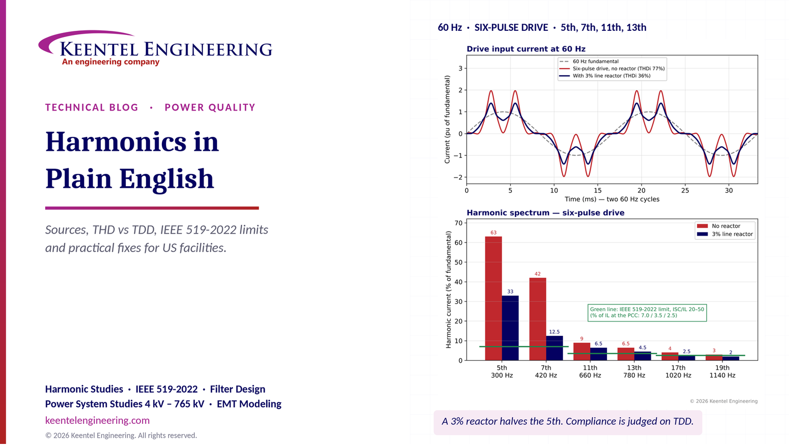
Keentel Engineering modeled a common situation: a 480 V switchboard fed by a 2,000 kVA, 5.75% impedance transformer from a 13.8 kV utility service, supplying 1,000 kVA of six-pulse variable frequency drives. We compared drives with no input reactor against drives with a 3% AC line reactor. We then scaled the same drive load to a 10 MW facility metered at 13.8 kV.
| Quantity | No reactor | 3% line reactor |
|---|---|---|
| Drive current THD (THDi) | 76.7% | 36.3% |
| 5th harmonic current (% of fundamental) | 63% | 33% |
| 480 V bus 5th harmonic voltage | 9.7% | 5.1% |
| 480 V bus voltage THD (THDv) | 14.1% | 6.6% |
| IEEE 519 Table 1 limit at 480 V (individual / THD) | 5% / 8% | 5% / 8% |
| Result at the 480 V bus | Fails both limits | Passes THD; 5th harmonic slightly over |
| True power factor at 0.97 displacement power factor | — | 0.91 |
For the 10 MW facility at 13.8 kV, with 3 MW of the same drives, a 12 kA utility fault level and a short-circuit ratio of 27, the 5th harmonic current reaches 9.9% of maximum demand current against a 7.0% limit, and total demand distortion (TDD) reaches 10.9% against an 8.0% limit. Replacing the drives with active-front-end or 18-pulse units brings TDD to about 1.5%.

Figure 1. Keentel's illustrative six-pulse drive analysis at 60 Hz. Top: the distorted drive input current compared with its 60 Hz fundamental. Bottom: the harmonic spectrum with and without a 3% line reactor, with the IEEE 519-2022 individual current limit for a short-circuit ratio of 20–50 (7% of maximum demand current for h < 11) shown for reference. The limit applies to the facility's total current at the point of common coupling, not to one drive.
Five lessons
- Harmonics are a current problem that becomes a voltage problem. Equipment injects harmonic current. That current flows through the impedance of the transformer and the utility system and distorts the voltage that everyone else on the bus receives.
- THD alone can mislead. A drive at 30% load can show 80% current THD while injecting very little harmonic current. IEEE 519 uses TDD, which compares harmonic current with the facility's maximum demand current, for exactly this reason.
- "No triplen harmonics" is only true for balanced three-wire loads. Single-phase electronics — servers, PCs, LED drivers — produce large 3rd harmonics that add up in the neutral. A neutral can carry 1.7 times the phase current.
- Capacitors and harmonics are a dangerous pair. A power factor capacitor bank can tune the system to resonate near the 5th or 7th harmonic and amplify distortion many times over.
- IEEE 519 applies at the point of common coupling, not to each machine. The 2022 edition is a standard with "shall" requirements, revised even-harmonic limits, statistical measurement rules and a decision path for sites with significant inverter-based generation.
Engineering review of common statements about harmonics
| Statement often made | Keentel's check |
|---|---|
| "Fundamental 50 Hz; 3rd = 150 Hz; 5th = 250 Hz." | Correct for 50 Hz systems abroad. US systems run at 60 Hz: 3rd = 180 Hz, 5th = 300 Hz, 7th = 420 Hz, 11th = 660 Hz, 13th = 780 Hz. |
| "Six-pulse converters produce h = 6k ± 1 (5, 7, 11, 13, 17, 19)." | Correct for balanced supply voltages and identical phase conditions. Voltage unbalance, unequal commutation and DC ripple add non-characteristic harmonics, including small 3rd and even harmonics. |
| "Higher orders have lower amplitude." | Broadly true. The ideal square-wave rule is Ih = I1/h (5th = 20%), but real drives without reactors show 5th harmonics of 60–80% because the DC bus capacitor charges in sharp pulses. Reactance reduces this considerably. |
| "There are no triplen harmonics in a six-pulse converter." | True for a balanced three-phase, three-wire converter. False for the facility as a whole: single-phase electronic loads are the largest triplen source in commercial buildings and data centers. |
| "THDi and THDv are used to assess severity." | Partly. IEEE 519 voltage limits use THD, but current limits use TDD and individual harmonics as a percentage of maximum demand current IL, set by the ratio ISC/IL at the PCC. THDi is a useful diagnostic, not the compliance metric. |
| "IEEE 519-2022 Table 1 limits: ≤1 kV 5%/8%; 1–69 kV 3%/5%; 69–161 kV 1.5%/2.5%; >161 kV 1.0%/1.5%." | Correct. A note allows higher THD on high-voltage systems where it is caused by an HVDC terminal whose effect is attenuated at points where users may connect. |
| "Weekly 95th-percentile 10-minute values < Table 1; daily 99th-percentile 3-second values < 1.5 × Table 1." | Correct for voltage. Current has parallel rules: weekly 95th-percentile 10-minute values below the table, weekly 99th-percentile 10-minute values below 1.5 times the table, and daily 99th-percentile 3-second values below 2.0 times the table. |
| "Harmonics cause maloperation of protection." | Possible but less common with modern numerical relays, which filter to the fundamental. The bigger risks are thermal-magnetic and electronic trip units responding to peak or true RMS current, ground-fault sensing on neutrals carrying triplens, and capacitor fuse operation. |
Part B — Harmonics Explained: From First Principles to IEEE 519-2022 Compliance
1. What harmonics are, in plain English
1.1 The clean wave
The voltage at a US wall outlet, a 480 V switchboard or a 13.8 kV feeder is designed to be a smooth sine wave. It rises, falls and repeats 60 times per second. That repetition rate is the fundamental frequency, 60 hertz (Hz). Generators produce this wave, and transformers, lines and cables carry it with very little change.
When a simple load such as a heater or an incandescent lamp is connected, the current it draws is also a smooth sine wave. Engineers call such loads linear: double the voltage and the current doubles, and the shape of the current matches the shape of the voltage.
1.2 The bent wave
Many modern loads are nonlinear. Inside nearly every drive, UPS, computer power supply and LED driver is a rectifier — a set of diodes or transistors that converts AC to DC — followed by a capacitor that stores energy. The capacitor only takes current when the incoming voltage is higher than the capacitor's own voltage. That happens near the top of each half-cycle. The result is a current that flows in short, sharp pulses rather than a smooth wave.
A pulse-shaped current is still periodic: it repeats exactly every 1/60 of a second. A useful mathematical fact, first shown by the French mathematician Joseph Fourier, is that any repeating waveform can be built by adding together sine waves whose frequencies are whole-number multiples of the repetition rate. The pulse-shaped current can therefore be described as:
- a 60 Hz component (the fundamental), plus
- a 180 Hz component (the 3rd harmonic), plus
- a 300 Hz component (the 5th harmonic), plus
- a 420 Hz component (the 7th harmonic), and so on.
Each of these components is a harmonic. The number in front — 3rd, 5th, 7th — is the harmonic order, written h.

In words: the frequency of a harmonic equals its order times 60 Hz. The 5th harmonic is 5 × 60 = 300 Hz; the 11th is 660 Hz; the 50th, the highest order IEEE 519 evaluates, is 3,000 Hz.
The full current is the sum of all of them:
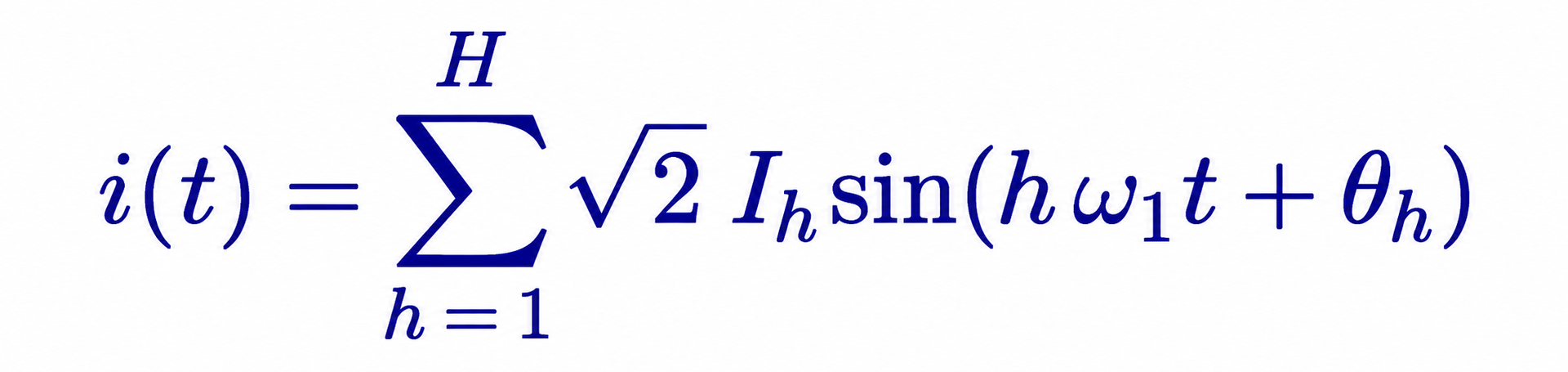
In words: the actual current at any instant is the sum of the fundamental and each harmonic, where Ih is the RMS size of each harmonic, ω₁ = 2π × 60 rad/s is the fundamental angular frequency, and θh is the timing (phase angle) of each harmonic.
An analogy. Think of a piano and a tuning fork both playing middle A. The tuning fork produces an almost pure tone. The piano produces the same note plus a set of quieter overtones at two, three and four times the frequency. Your ear hears both as "A," but the piano sounds richer because of the overtones. A nonlinear load is the piano: it draws the same 60 Hz "note" as a heater, plus overtones. In music the overtones are pleasant. In a power system they cause heating and interference.
1.3 Odd, even and triplen harmonics
Most electrical equipment draws the same shape of current on the positive and negative halves of each cycle. That symmetry cancels all even harmonics (2nd, 4th, 6th). So in practice the harmonics that matter are the odd ones: 3rd, 5th, 7th, 9th, 11th, 13th and so on. Even harmonics appear when something is asymmetric — a transformer energizing with DC offset (inrush), a half-wave rectifier, a faulty drive, or a geomagnetic disturbance.
Odd multiples of three — the 3rd, 9th, 15th, 21st — are called triplen harmonics. They behave differently from the others in three-phase systems, as Section 4 explains.
1.4 Harmonic sequence: why the 5th fights motors
In a three-phase system the three phase currents are 120° apart. When harmonics are present, the harmonics of each phase are also shifted, but by h × 120°. That shift gives each harmonic order a "sequence":
| Harmonic order h | Sequence | What it does in a three-phase system |
|---|---|---|
| 1, 7, 13, 19 | Positive | Rotates in the same direction as the fundamental |
| 5, 11, 17, 23 | Negative | Rotates backward — produces braking torque in motors |
| 3, 9, 15, 21 (triplens) | Zero | All three phases in step — adds in the neutral, circulates in delta windings |
This table holds for balanced conditions and is the reason motor designers worry most about the 5th harmonic: it creates a magnetic field that rotates the wrong way.
2. Where harmonics come from
2.1 The usual suspects
| Source | Where you find it | Dominant harmonic orders | Typical current THD |
|---|---|---|---|
| Six-pulse variable frequency drive (no reactor) | Pumps, fans, compressors, conveyors | 5, 7, 11, 13 | 70–100%+ at full load on a stiff source |
| Six-pulse VFD with 3–5% AC reactor or DC choke | Most new commercial and industrial VFDs | 5, 7, 11, 13 | 30–45% |
| 12-pulse drive or rectifier | Large drives, older UPS, DC plants | 11, 13, 23, 25 | 8–15% |
| 18-pulse drive | Large pumps and fans where compliance matters | 17, 19, 35, 37 | 4–6% |
| Active front end (AFE) drive or UPS rectifier | New premium drives, double-conversion UPS | Low-order small; switching frequency band | 3–5% |
| Single-phase switch-mode power supply without power factor correction | Older PCs, monitors, small electronics | 3, 5, 7, 9 | 80–130% |
| Server power supply with active PFC | Modern servers and network gear | Small 3rd and 5th | 5–15% at moderate load |
| LED drivers and fluorescent electronic ballasts | Lighting | 3, 5 | 10–30% (good drivers), higher for cheap ones |
| Battery chargers and DC drives (thyristor) | Forklift fleets, telecom, mills | 5, 7, 11, 13 | 25–40% |
| EV chargers (Level 2 and DC fast) | Parking, fleet depots, travel centers | 3, 5 (single-phase); 5, 7 (three-phase) | 3–25% depending on design |
| Solar, battery and wind inverters | PV, BESS, Type 3/4 wind | High-frequency switching band; small low orders | Below 5% total rated distortion at rated output |
| Arc furnaces and welders | Steel, foundries, fabrication | All orders, including even and interharmonics | Highly variable, 20–30%+ |
| Saturated transformers and reactors | Overexcited transformers, inrush | 2, 3, 5 | Event-dependent |
Typical values vary with load level, supply stiffness and design. They are illustrative, not guarantees; manufacturer data and measurements govern.
What this means for you. A facility with a few small drives on a large transformer rarely has a problem. Trouble starts when nonlinear load becomes a large share of the transformer — roughly above 25–30% — or when power factor capacitors are added to the same bus.
2.2 Why AI data centers and modern plants are different
Large new loads are often almost entirely electronic. A data center's IT load passes through UPS rectifiers and server power supplies; its cooling plant runs on drives. Many modern UPS systems use transistor (IGBT) rectifiers that draw nearly sinusoidal current, and modern server supplies have active power factor correction. That is good news. But three issues remain:
- Partial load. Power electronics are cleanest near rated output. At the 20–40% loading typical in a redundant (2N) data center, current THD rises.
- Generator operation. A standby generator has a much higher internal impedance than the utility. The same harmonic current produces far more voltage distortion on generator power, which can upset generator voltage regulators and UPS synchronization.
- Scale. Hundreds of megawatts of electronic load connected at 138 kV, 230 kV or 345 kV can interact with transmission-system resonances. Utilities now ask large-load customers for harmonic studies as part of interconnection.
3. The six-pulse rule and why real spectra look different
3.1 Characteristic harmonics
A three-phase, six-pulse rectifier uses six diodes or thyristors. Each conducts for one-third of a cycle. Under ideal, balanced conditions, the current in each line is a stepped waveform. Fourier analysis of that waveform shows only harmonics of order

In words: for a converter with p pulses, the characteristic harmonics are one above and one below each multiple of p. For a six-pulse converter (p = 6) that gives 5, 7, 11, 13, 17, 19, 23, 25… For a 12-pulse converter (p = 12), the 5th, 7th, 17th and 19th cancel, leaving 11, 13, 23, 25. For an 18-pulse converter (p = 18), the lowest pair is 17 and 19.
For the idealized stepped waveform the harmonic sizes follow a simple rule:
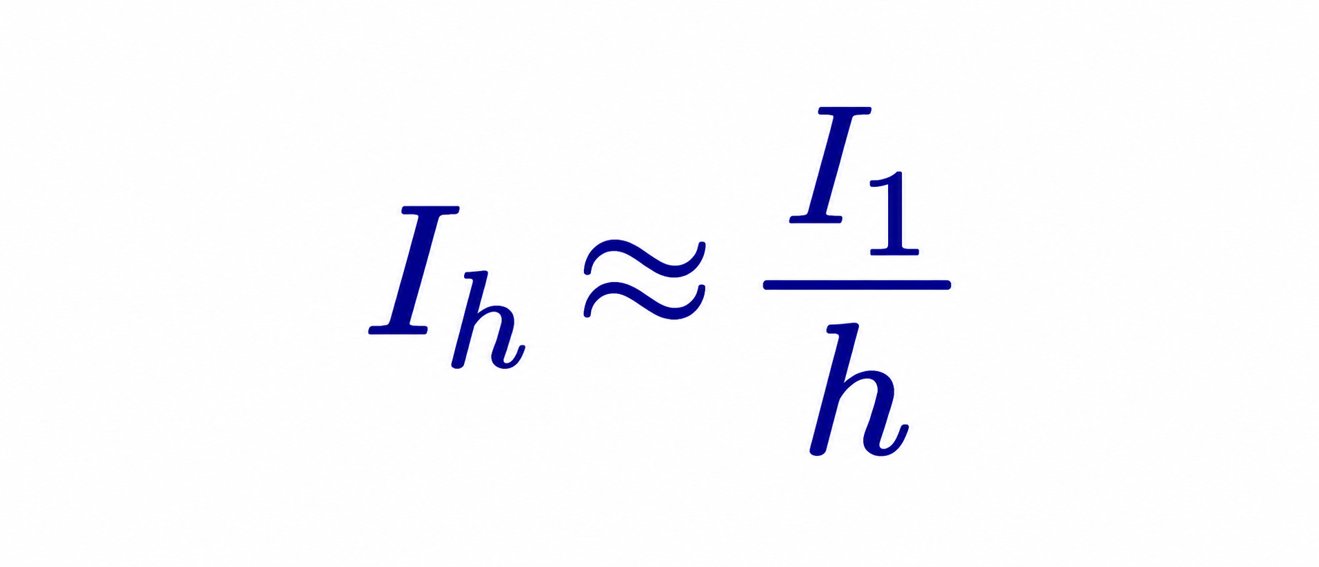
In words: in the ideal case, the 5th harmonic is one-fifth (20%) of the fundamental, the 7th is about 14%, the 11th about 9% and the 13th about 8%. That gives an ideal current THD of roughly 30% when all characteristic orders up to the 49th are included.
3.2 Why real drives look worse
Modern drives use a diode bridge feeding a large DC bus capacitor. The capacitor makes the input current pulse twice per half-cycle in narrow "rabbit ears," not the flat-topped steps of the ideal case. Narrow pulses are rich in low-order harmonics. A six-pulse drive with no reactor on a stiff supply typically shows a 5th harmonic of 60–80% and a current THD of 75–100% or more.
Adding inductance — an AC line reactor ahead of the drive or a DC choke in the DC bus — stretches the pulses and lowers their peaks. Typical results:
| Six-pulse drive input arrangement | Typical 5th | Typical 7th | Typical THDi |
|---|---|---|---|
| No reactor, stiff supply | 60–80% | 35–50% | 75–100%+ |
| 3% AC line reactor or equivalent DC choke | 30–40% | 10–15% | 35–45% |
| 5% AC line reactor | 25–33% | 8–12% | 30–38% |
| AC reactor plus DC choke | 22–30% | 7–10% | 28–35% |
These ranges are indicative and depend on load level and the stiffness of the supply.
3.3 Non-characteristic harmonics
Real systems are never perfectly balanced. A 1–2% voltage unbalance between phases causes a six-pulse drive to draw some 3rd harmonic current and makes the 5th and 7th unequal across phases. Unequal firing in thyristor converters produces even harmonics. These "non-characteristic" harmonics are usually small but matter for compliance because IEEE 519 limits apply to every order, and the 2022 edition sets explicit limits on even orders.
4. Triplen harmonics and the overloaded neutral
4.1 The cancellation that does not happen
In a balanced three-phase system with linear loads, the three phase currents add to zero in the neutral. That is why neutrals have traditionally been the same size as, or smaller than, the phase conductors.
Triplen harmonics break this rule. Because the 3rd harmonic of each phase is shifted by 3 × 120° = 360°, the three 3rd-harmonic currents are exactly in step. They do not cancel in the neutral — they add.

In words: on a balanced four-wire system, the neutral current equals three times the combined triplen current of one phase. The fundamental, 5th, 7th and other non-triplen currents cancel in the neutral.
4.2 Worked example — neutral current in a 208Y/120 V panel
A 208Y/120 V panel feeds legacy single-phase electronic equipment without power factor correction. Each phase carries 100 A RMS, and measurements show the harmonic spectrum relative to the fundamental: 3rd 75%, 5th 45%, 7th 20%, 9th 10%.
Step 1 — find the fundamental. The RMS current is the square root of the sum of the squares of all components:

So I₁ = 100 / 1.347 = 74.2 A. The 3rd harmonic is 0.75 × 74.2 = 55.7 A and the 9th is 7.4 A.
Step 2 — add the triplens in the neutral:

The neutral carries about 168 A while each phase carries 100 A — 1.68 times the phase current. A neutral sized like a phase conductor would be overloaded by about 68%.
What this means for you.
In panels serving many single-phase electronic loads, size the neutral for up to about 1.7–2.0 times phase current or use a 200% neutral, and use K-rated or harmonic-mitigating transformers. The NEC recognizes the issue: under NEC 310.15(E)(3), the neutral of a four-wire wye circuit where the major portion of the load is nonlinear must be counted as a current-carrying conductor for ampacity adjustment. Modern servers with active PFC have far lower 3rd harmonic, so measure before assuming the worst.
4.3 Where triplens go: the delta winding
A delta-wye transformer is the usual supply for 208Y/120 V and 480Y/277 V panels. Triplen currents from the wye side flow into the transformer, but they cannot pass through the delta winding to the primary lines. Instead they circulate around the delta, heating the transformer. That is why triplens rarely show up at the 13.8 kV service but can overheat the building transformer and its secondary neutral. The "missing" triplens at the primary are not gone; they have become transformer losses.
5. Measuring distortion: THD, TDD, RMS and true power factor
5.1 Total harmonic distortion
THD compares the combined size of all harmonics with the fundamental:
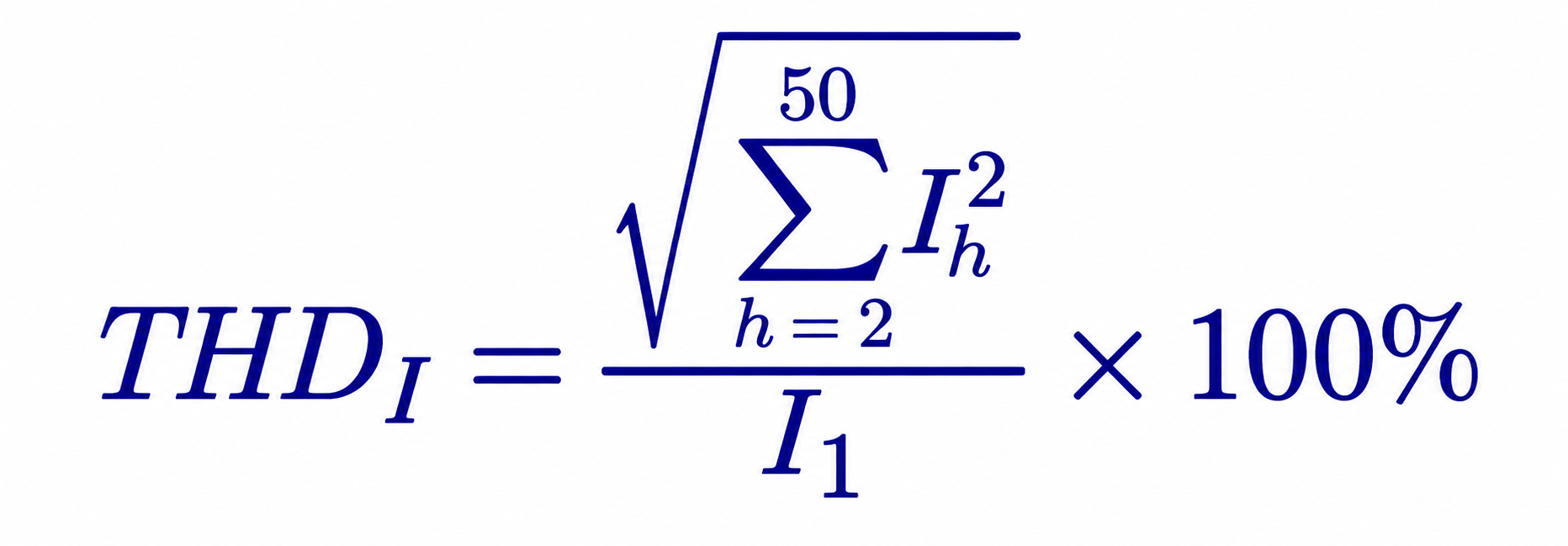
In words: square each harmonic, add the squares, take the square root, and divide by the fundamental. IEEE 519 evaluates harmonics up to and including the 50th order (3,000 Hz at 60 Hz). Note that the I₁ and V₁ in these formulas are 60 Hz quantities in US practice.
5.2 Worked example — THD from a measured spectrum
A power quality meter on a 480 V drive feeder reports a fundamental of 420 A and the following harmonic currents:
| Order | 5 | 7 | 11 | 13 | 17 | 19 |
|---|---|---|---|---|---|---|
| Current (A) | 138.6 | 52.5 | 27.3 | 18.9 | 10.5 | 8.4 |
| % of fundamental | 33.0 | 12.5 | 6.5 | 4.5 | 2.5 | 2.0 |
The combined harmonic current is the square root of the sum of squares: √(138.6² + 52.5² + 27.3² + 18.9² + 10.5² + 8.4²) = 152.5 A. Current THD = 152.5 / 420 = 36.3%.
The total RMS current the conductor carries is √(420² + 152.5²) = 446.8 A — about 6.4% more than the fundamental alone. That relationship is general:

In words: the RMS current that heats cables and transformers grows with THD. At 36% THD it is 6.4% higher; at 100% THD it is 41% higher.
5.3 Total demand distortion — the metric IEEE 519 actually uses for current
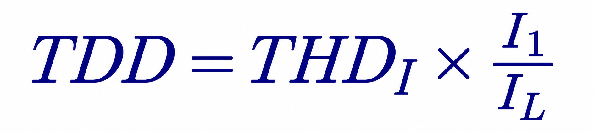
THD has a weakness. Because it divides by the present fundamental current, a lightly loaded drive can show a very high THD while injecting only a little harmonic current. IEEE 519 therefore limits current distortion using total demand distortion (TDD):
In words: TDD is the same harmonic current divided not by today's fundamental but by IL, the facility's maximum demand load current at the point of common coupling. IEEE 519-2022 defines IL as the maximum 15- or 30-minute demand current over the previous 12 months, or a projected value for new facilities.
The two are linked simply:
5.4 Worked example — why THD misleads at light load
A facility has a maximum demand current of IL = 1,000 A.
| Condition | Fundamental I₁ | Measured THDi | Harmonic current | TDD |
|---|---|---|---|---|
| Night, light load | 300 A | 40% | 120 A | 120/1,000 = 12% |
| Day, full load | 1,000 A | 30% | 300 A | 300/1,000 = 30% |
At night the THDi looks alarming at 40%, but the actual harmonic current — 120 A — is small. During the day THDi looks better at 30%, but the harmonic current is 300 A and the TDD is 30%. The daytime condition is the one that heats equipment and distorts the utility's voltage. TDD captures that; THDi does not.
What this means for you. When a vendor or a meter report quotes "current THD," ask: "At what load, and what is the TDD at the point of common coupling?" Compliance is judged on TDD and individual harmonics as a percentage of IL.
5.5 True power factor
Power factor is the ratio of real power (kW) to apparent power (kVA). With harmonics present it has two parts: the displacement power factor, which reflects the phase shift of the fundamental, and the distortion factor, which reflects harmonic current.
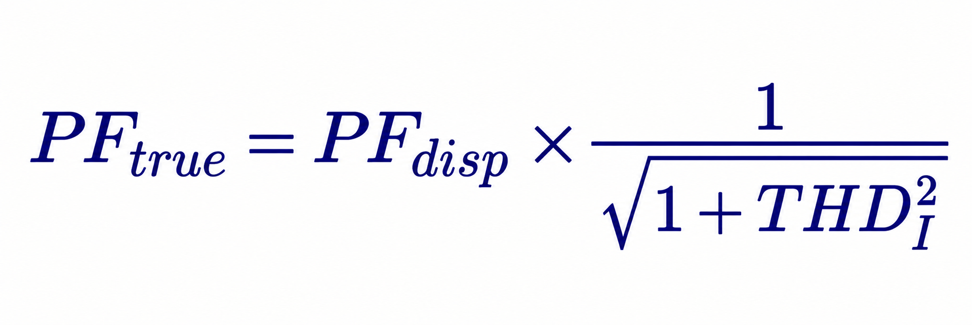
In words: harmonics lower the true power factor even when the fundamental current is perfectly in phase. For the drive in Section 5.2, with a displacement power factor of 0.97 and 36.3% THD, the distortion factor is 1/√(1 + 0.363²) = 0.940, so the true power factor is 0.97 × 0.940 = 0.91.
This explains a common puzzle: drives "have a power factor of 0.97" on the data sheet, yet the utility meter shows 0.91. Adding capacitors does not fix distortion power factor and can make harmonics worse.
6. From harmonic current to harmonic voltage
6.1 The mechanism
Harmonic currents flow from the nonlinear load back through the facility transformer and the utility system. Every part of that path has impedance, and impedance (mostly inductive reactance) grows with frequency. Each harmonic current therefore creates a harmonic voltage drop:

In words: the harmonic voltage at a bus equals the harmonic current multiplied by the system reactance at that harmonic's frequency, which for an inductive source is h times the 60 Hz reactance X₁. This is why a weak source (high impedance) suffers more voltage distortion from the same load.
That distorted voltage is then supplied to every other customer and every other load on the bus. That is why utilities care, and why IEEE 519 splits responsibility: customers limit the harmonic current they inject; utilities limit the voltage distortion they deliver.
6.2 Worked example — 480 V drive bus on a 2,000 kVA transformer
Data: a 2,000 kVA, 13.8 kV–480Y/277 V transformer with 5.75% impedance (treated as reactance), a 13.8 kV utility source of 500 MVA short-circuit capacity, and 1,000 kVA of six-pulse drives with 3% line reactors (spectrum as in Section 5.2).
Step 1 — base impedance at 480 V:
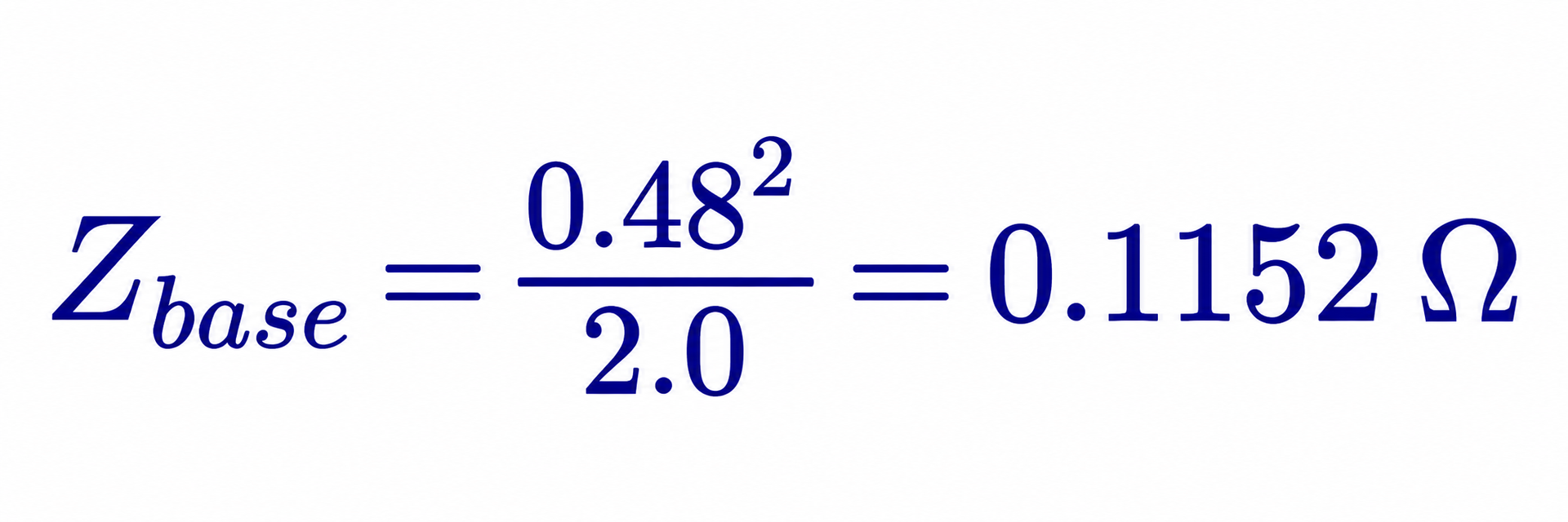
Step 2 — source reactance at 60 Hz, referred to 480 V: the transformer contributes 0.0575 × 0.1152 = 0.00662 Ω, and the utility contributes 0.48²/500 = 0.00046 Ω, giving X₁ = 0.00708 Ω.
Step 3 — drive fundamental current: 1,000 kVA / (√3 × 0.48 kV) = 1,203 A.
Step 4 — harmonic voltages, compared with the 277 V phase-to-neutral fundamental:
| Order h | Ih (A) | Vh = Ih × h × X₁ (V) | Vh (% of 277 V) |
|---|---|---|---|
| 5 | 396.9 | 14.06 | 5.07 |
| 7 | 150.4 | 7.46 | 2.69 |
| 11 | 78.2 | 6.09 | 2.20 |
| 13 | 54.1 | 4.99 | 1.80 |
| 17 | 30.1 | 3.62 | 1.31 |
| 19 | 24.1 | 3.24 | 1.17 |
| THDv | 6.64% |
The bus voltage THD of 6.6% is within the IEEE 519 limit of 8% for buses at 1 kV and below, but the 5th harmonic at 5.07% is just above the 5% individual limit. Without the line reactors the same calculation gives a 5th harmonic voltage of 9.7% and THDv of 14.1% — clearly unacceptable.
This simple method ignores the cancellation that occurs when harmonics from different drives are not in phase, background distortion from the utility, and the effect of capacitors and cable capacitance. It is conservative for screening. A full harmonic study models those effects.
What this means for you.
Voltage distortion on your own 480 V bus is usually a sign of what is happening inside your facility, not a utility compliance failure. IEEE 519 applies at the point of common coupling with the utility. But high internal voltage distortion still affects sensitive equipment, generators and capacitors, so it deserves the same attention.
7. What harmonics do to equipment — quantified
7.1 Transformers: extra heat in the windings
A transformer's nameplate rating assumes a clean 60 Hz load current. Harmonic currents add two kinds of extra loss:
- Resistive (I²R) loss rises with the RMS current, as shown in Section 5.2.
- Winding eddy-current loss rises roughly with the square of frequency. A 5th harmonic current produces about 25 times the eddy loss of the same current at 60 Hz.
Two closely related numbers capture this effect. Dry-type transformers listed to UL 1561 (low voltage) and UL 1562 (medium voltage) can carry a K-factor rating. IEEE Std C57.110 uses the harmonic loss factor FHL to derate standard transformers.
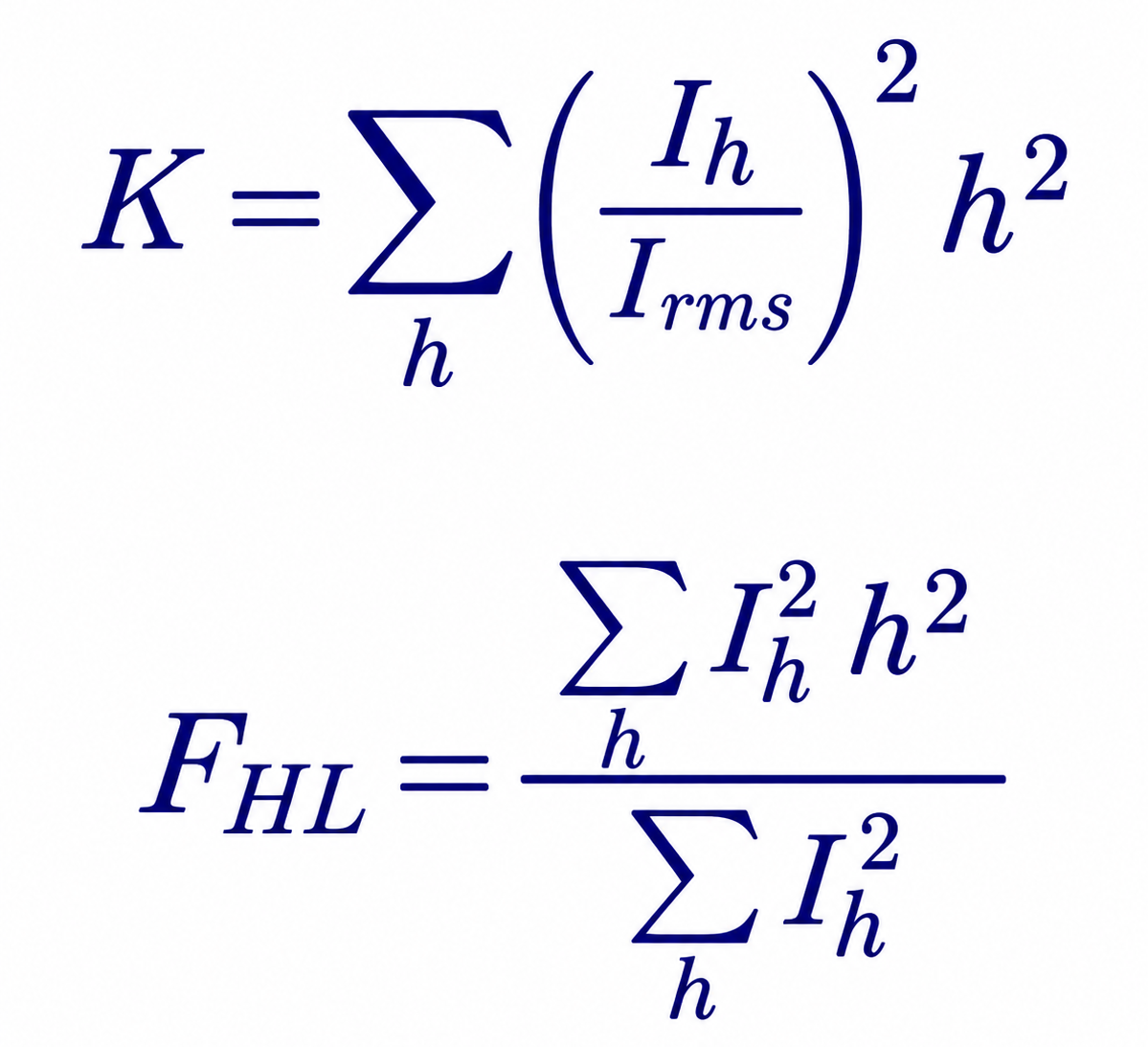
In words: both weight each harmonic by the square of its order, so high-order harmonics count heavily. For a given spectrum the two give the same number; K-factor is used to specify a transformer that can carry the load, while FHL is used to derate an existing standard transformer.
For a dry-type transformer, IEEE C57.110 gives the maximum permissible per-unit current as:
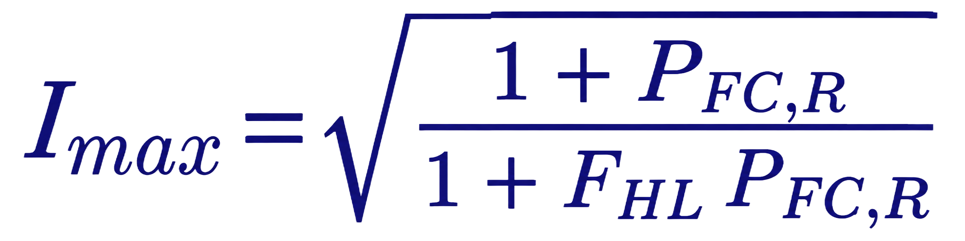
In words: the transformer can carry less current as the harmonic loss factor FHL rises, scaled by P(EC-R), the rated winding eddy loss as a fraction of rated I²R loss (taken here as 0.15).
7.2 Worked example — transformer derating
| Load spectrum | K-factor (= FHL) | Maximum loading of a standard transformer |
|---|---|---|
| Six-pulse drives with 3% reactors (5th 33%, 7th 12.5%, 11th 6.5%, 13th 4.5%, 17th 2.5%, 19th 2%) | 5.0 | 81% of nameplate |
| Legacy single-phase electronics (3rd 75%, 5th 45%, 7th 20%, 9th 10%) | 7.7 | 73% of nameplate |
A standard 1,000 kVA dry-type transformer feeding the drive load should be loaded to no more than about 810 kVA, and to about 730 kVA for the legacy electronic load, unless it is K-rated. A K-13 transformer covers either case with margin. The exact derating depends on the manufacturer's eddy-loss data, so ask for P(EC-R) when buying.
7.3 Cables and neutrals
At harmonic frequencies, current crowds toward the outer surface of a conductor (skin effect) and toward adjacent conductors (proximity effect). For typical building and plant cables up to about 500 kcmil this adds only a few percent to losses at the 5th and 7th. The larger cable issue is the triplen neutral current described in Section 4.
7.4 Power factor capacitors
Capacitors are the components most often damaged by harmonics. Their impedance falls as frequency rises, so they act as a magnet for harmonic current. IEEE Std 18-2012 sets the continuous limits for shunt power capacitors, including harmonics:
| Quantity | IEEE 18-2012 continuous limit |
|---|---|
| RMS voltage | 110% of rated |
| Crest (peak) voltage, including harmonics | 120% of rated peak |
| RMS current, including harmonics | 135% of nominal |
| Reactive power | 135% of rated kvar |
On the 480 V bus of Section 6.2, a capacitor rated at bus voltage would see an RMS current of about 110% and a worst-case peak voltage (if all harmonics peaked together) of about 114% — inside the limits. The danger is resonance, which can multiply those values several times over.
7.5 Resonance: the amplifier you did not order
A capacitor bank and the inductive source together form a tuned circuit. At one frequency, the parallel resonance frequency, the combination presents a very high impedance to harmonic current, and the harmonic voltage at that frequency is amplified. A quick estimate:
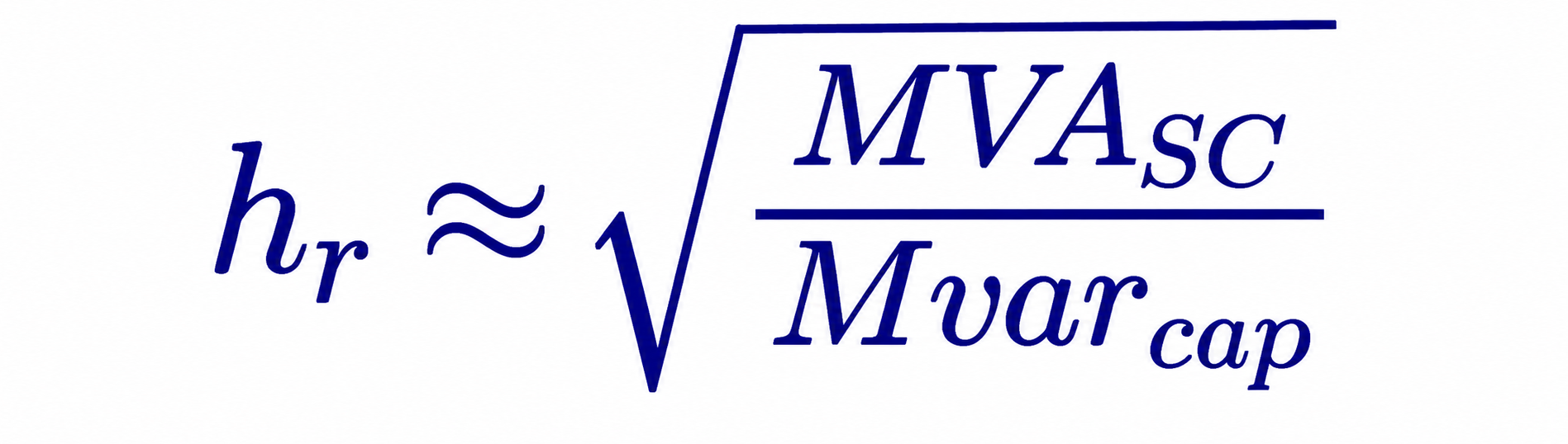
In words: the resonant harmonic order is the square root of the bus short-circuit MVA divided by the capacitor Mvar.
- On the 480 V bus of Section 6.2 (about 32.5 MVA short-circuit capacity including the utility), adding a 600 kvar power factor capacitor gives hr = √(32.5/0.6) ≈ 7.4 — right between the 7th harmonic and the 5th/7th pair that drives produce in volume.
- On a 13.8 kV bus with 287 MVA short-circuit capacity, a 6 Mvar capacitor bank gives hr = √(287/6) ≈ 6.9 — very close to the 7th.
Both are classic recipes for capacitor fuse blowing, capacitor failure and severe voltage distortion. The usual fix is to convert the bank to a detuned filter by adding a series reactor that tunes the combination below the 5th harmonic (commonly about the 4.7th or 4.2nd). Keentel's companion articles on
harmonic resonance and on active harmonic filters treat the resonance mathematics and filter sizing in depth.
7.6 Motors and generators
The 5th harmonic is negative-sequence, so it creates a backward-rotating field. That produces extra rotor heating and torque pulsations at six times the fundamental frequency (360 Hz) as the 5th and 7th fields interact with the forward field. NEMA MG 1 recommends derating induction motors when voltage distortion is significant; at a harmonic voltage factor around 0.05 the derating is small, but above about 0.10 it becomes meaningful.
Standby generators are more sensitive still. Their subtransient reactance is typically 10–20% on the generator base, several times higher than a utility source seen through a transformer. The same drive or UPS load that produces 5% THDv on utility power can produce 15–20% on a generator, upsetting the automatic voltage regulator, overheating the generator's damper windings and making UPS systems refuse to synchronize. Generator sizing for nonlinear loads should account for this explicitly.
7.7 Protection, metering and electronics
- Modern numerical relays filter their inputs to the 60 Hz fundamental for most protective elements, so harmonics rarely cause them to misoperate. But some elements deliberately use true RMS or peak values; check the setting basis.
- Thermal-magnetic breakers and fuses respond to RMS heating and can trip at lower fundamental currents when harmonics are high. Electronic trip units that sample peak current can trip early on peaky waveforms.
- Ground-fault protection that senses neutral current on 480Y/277 V or 208Y/120 V systems can trip on triplen neutral current that is not a ground fault at all.
- Revenue and panel meters that are not true-RMS can misread current by 10–30%.
- Electronic controls and communication circuits can be disturbed by zero-crossing distortion, notching from thyristor converters and coupled high-frequency noise.
8. IEEE Std 519-2022 in plain English
8.1 What the standard is — and is not
IEEE Std 519 has been the reference for harmonic limits in North America since 1981. The 2022 edition, approved in 2022, made important changes:
- It became a standard rather than a "recommended practice and requirements," and many "should" statements became "shall." Limits are now called limits, not recommended values.
- The limits apply at the point of common coupling (PCC) — the point on the utility system nearest the customer where another customer is, or could be, served. In practice this is usually the utility metering point or the high side of the customer's service transformer. The limits are not intended for individual pieces of equipment inside the facility.
- Responsibility is shared. Customers limit harmonic current injection (Tables 2–4). Utilities limit voltage distortion (Table 1), assuming customers meet their current limits.
- For sites where rated generation is significant (the 2022 edition uses a threshold of 10% of annual average load demand), users are pointed to IEEE Std 1547 (distribution) or IEEE Std 2800 (transmission) for current distortion limits on the generation.
- Even harmonics received new limits (Section 8.5), and the informative annex on interharmonics — frequencies that are not integer multiples of 60 Hz, which can cause lighting flicker — was substantially reworked.
IEEE 519 is not a law. It becomes binding when a utility tariff, interconnection agreement, specification or contract adopts it. Many US utilities do, and many large-load interconnection procedures now require a harmonic study demonstrating compliance.
8.2 Table 1 — voltage distortion limits (utility responsibility)
| Bus voltage at the PCC | Individual harmonic (%) | Total harmonic distortion THD (%) |
|---|---|---|
| V ≤ 1.0 kV | 5.0 | 8.0 |
| 1 kV < V ≤ 69 kV (e.g., 4.16, 13.8, 34.5, 69 kV) | 3.0 | 5.0 |
| 69 kV < V ≤ 161 kV (e.g., 115, 138, 161 kV) | 1.5 | 2.5 |
| V > 161 kV (e.g., 230, 345, 500, 765 kV) | 1.0 | 1.5 |
A note to the table allows high-voltage systems to have up to 2.0% THD where the cause is an HVDC terminal whose effects are attenuated at points in the network where future users may connect.
8.3 Table 2 — current distortion limits for 120 V through 69 kV (customer responsibility)
Current limits depend on the
short-circuit ratio ISC/IL at the PCC, where ISC is the maximum short-circuit current at the PCC and IL is the maximum demand load current. A large customer on a weak system (low ratio) gets tight limits because its harmonics distort the shared voltage more; a small customer on a strong system (high ratio) gets looser limits.
| ISC/IL | 3 ≤ h < 11 | 11 ≤ h < 17 | 17 ≤ h < 23 | 23 ≤ h < 35 | 35 ≤ h ≤ 50 | TDD |
|---|---|---|---|---|---|---|
| < 20 | 4.0 | 2.0 | 1.5 | 0.6 | 0.3 | 5.0 |
| 20 < 50 | 7.0 | 3.5 | 2.5 | 1.0 | 0.5 | 8.0 |
| 50 < 100 | 10.0 | 4.5 | 4.0 | 1.5 | 0.7 | 12.0 |
| 100 < 1000 | 12.0 | 5.5 | 5.0 | 2.0 | 1.0 | 15.0 |
| > 1000 | 15.0 | 7.0 | 6.0 | 2.5 | 1.4 | 20.0 |
All values are percentages of IL. Tables 3 and 4 set tighter limits for PCCs above 69 kV through 161 kV and above 161 kV respectively; the TDD limit for the lowest ratio band falls to 2.5% above 69 kV and is lower still above 161 kV. All generation equipment, whatever its actual short-circuit ratio, is limited to the "< 20" row in the 2014 approach; in the 2022 edition, sites with significant generation follow the IEEE 1547/2800 path described above. Always confirm against the current published standard and your utility's requirements.
8.4 How compliance is measured
IEEE 519 recognizes that harmonics vary from minute to minute. It therefore judges compliance statistically, typically over at least one week of measurement:
| Quantity | Statistic | Must be less than |
|---|---|---|
| Voltage | Weekly 95th percentile of 10-minute values | Table 1 values |
| Voltage | Daily 99th percentile of 3-second values | 1.5 × Table 1 values |
| Current | Weekly 95th percentile of 10-minute values | Tables 2–4 values |
| Current | Weekly 99th percentile of 10-minute values | 1.5 × Tables 2–4 values |
| Current | Daily 99th percentile of 3-second values | 2.0 × Tables 2–4 values |
In plain English: the distortion may briefly exceed the table values — for example during motor starting or a production surge — but it must be below the limits about 95% of the time over a week, and short bursts must stay within a margin. Measurements should be made with instruments that meet the recognized power quality measurement methods (Class A instruments for formal compliance, evaluating up to the 50th harmonic).
8.5 Even harmonics in the 2022 edition
The 2014 edition limited even harmonics to 25% of the odd-harmonic limits in the same range. The 2022 edition, as published summaries describe it, applies limits to all orders and allows even harmonics of orders 2, 4 and 6 up to 50% of the tabulated limits, and higher even orders the same limits as odd orders. The change reflects the growing population of active front ends, active filters and inverters whose switching produces some even-order content. Low-order even harmonics remain tightly limited because they usually indicate asymmetry, DC offset or equipment malfunction. Confirm the exact wording against the published standard.
8.6 Worked example — is a 10 MW facility compliant at 13.8 kV?
A US water and process facility is served at 13.8 kV. Its maximum demand is 10 MW at 0.95 power factor. The utility reports a maximum three-phase short-circuit current of 12 kA at the PCC. The facility has 3 MW of six-pulse drives with 3% line reactors; the rest of the load is linear.
Step 1 — maximum demand current:

Step 2 — short-circuit ratio: ISC/IL = 12,000/440 = 27.2. That places the facility in the 20–50 row: individual limits 7.0% (h < 11), 3.5% (11 ≤ h < 17), 2.5% (17 ≤ h < 23); TDD limit 8.0%. (The 12 kA corresponds to 287 MVA at 13.8 kV.)
Step 3 — drive fundamental current at 13.8 kV: 3,000 kW / (√3 × 13.8 × 0.95) = 132 A.
Step 4 — harmonic currents as a percentage of IL (conservatively assuming the drive harmonics add arithmetically):
| Order | Drive spectrum (% of drive I₁) | Harmonic current (A) | % of IL | Limit (% of IL) | Result |
|---|---|---|---|---|---|
| 5 | 33.0 | 43.6 | 9.9 | 7.0 | Fails |
| 7 | 12.5 | 16.5 | 3.7 | 7.0 | Passes |
| 11 | 6.5 | 8.6 | 1.9 | 3.5 | Passes |
| 13 | 4.5 | 5.9 | 1.3 | 3.5 | Passes |
| TDD | 36.3 (THDi) | 48.0 | 10.9 | 8.0 | Fails |
Step 5 — options. Replacing or retrofitting the drives with active-front-end or 18-pulse units at about 5% THDi gives a TDD of about 1.5%. An active harmonic filter sized for the 5th and 7th could achieve a similar result at the facility level. A passive 5th-harmonic tuned filter would also work but must be checked for resonance with the utility system and with any future capacitors.
What this means for you.
The same drives can be compliant on a strong system and non-compliant on a weak one. Ask your utility for the maximum short-circuit current at the PCC early in design. If the ratio is below 50, plan for low-harmonic drives or filtering from the start; it is much cheaper than retrofitting.
9. Inverter-based resources: solar, storage and wind
Solar PV, battery energy storage and full-converter wind turbines use pulse-width-modulated inverters with output filters. They are generally low-distortion sources. IEEE Std 1547-2018 (distribution-connected resources) and IEEE Std 2800-2022 (transmission-connected resources) limit their current distortion — total rated-current distortion (TRD) of 5% with individual limits by order, measured against rated current rather than present output. In practice, quality inverters measure 1–3% at rated output.
Three cautions apply:
- Percentages rise at low output. At 10% of rated output a 2% distortion (of rated current) looks like 20% THD. Limits referenced to rated current, like TDD, avoid this trap.
- Inverters change the system's impedance. Plant collector cables, inverter output filters and capacitor banks add capacitance. They can create resonances near the 5th to 13th harmonics on the 34.5 kV collector or at a 138 kV, 230 kV or 345 kV point of interconnection, amplifying background distortion that the plant did not create.
- Background distortion matters. Inverters can absorb or amplify existing voltage distortion depending on their control design. Utilities increasingly require harmonic impedance studies for new plants, sometimes using electromagnetic transient (EMT) simulation.
Keentel's articles on harmonic resonance and on
weak-grid inverter stability cover these interactions in depth.
10. Data centers and other electronic facilities
Data centers are a special case because almost all their load is electronic. Points to check:
- UPS rectifiers. Double-conversion UPS units with IGBT rectifiers typically draw less than 5% THDi at rated load, rising at low load. Older six-pulse or 12-pulse thyristor UPS rectifiers may need input filters.
- Server and network power supplies. Modern units with active power factor correction have low 3rd harmonic. Legacy equipment does not. Measure a representative panel rather than assuming.
- 208Y/120 V and 415Y/240 V distribution. Check neutral current and transformer K-factor as in Sections 4 and 7.
- Generator operation. Test UPS and generator compatibility at the actual load level. Generator THDv can be three to four times the utility THDv for the same load.
- Cooling plant. Chiller, pump, fan and cooling distribution unit drives often contribute more low-order harmonics than the IT load. Specify low-harmonic drives where the facility is large relative to the utility source.
- Large-load interconnection. Utilities and grid operators now treat large data centers as high-impact loads. Harmonic studies and power quality monitoring are increasingly part of interconnection requirements, alongside ride-through and dynamic studies.
11. How a harmonic study is done
A harmonic study answers four questions: How much harmonic current will the facility inject? What voltage distortion will it cause? Will any resonance amplify it? What is the cheapest reliable fix? Keentel's typical workflow:
- Gather data. Single-line diagram; utility short-circuit data (maximum and minimum) at the PCC; utility background distortion if known; transformer impedances; cable lengths; capacitor banks and filters; drive, UPS and inverter data sheets with harmonic spectra.
- Measure existing conditions. For existing facilities, install class-compliant power quality meters at the PCC and key buses for at least one week, capturing 10-minute and 3-second data up to the 50th harmonic.
- Build the model. Represent sources as harmonic current injections and the network as frequency-dependent impedances, including transformer phase shifts that can cancel 5th and 7th harmonics between delta-delta and delta-wye units.
- Run a frequency scan. Plot driving-point impedance versus frequency at each important bus to find resonances, for all credible system configurations (tie breakers open/closed, capacitor steps in/out, generator versus utility).
- Run harmonic load flow. Calculate harmonic currents and voltages and compare them with IEEE 519 at the PCC and with equipment limits (IEEE 18 for capacitors, C57.110 for transformers) inside the facility.
- Design mitigation. Compare options for performance, cost, losses, footprint and future flexibility.
- Verify. Measure again after installation and document compliance with the statistical criteria.
12. Fixing harmonics: options compared
| Mitigation | How it works | Typical resulting THDi (six-pulse load) | Relative cost | Best for | Watch out for |
|---|---|---|---|---|---|
| AC line reactor (3–5%) | Adds inductance; stretches current pulses | 30–45% | Low | Every six-pulse drive as a baseline | Small voltage drop; not enough alone for tight limits |
| DC bus choke | Inductance inside the drive | 30–45% | Low | Built into many drives | Same as above |
| 12-pulse drive with phase-shifting transformer | Two bridges 30° apart cancel the 5th and 7th | 8–15% | Medium | Large single drives | Needs balanced voltages; cancellation degrades with unbalance |
| 18-pulse drive | Three bridges 20° apart | 4–6% | Medium–high | Large pumps and fans | Size and weight; transformer losses |
| Active front end (AFE) drive | Transistor rectifier draws sinusoidal current | 3–5% | Medium–high | New drives, regeneration | High-frequency switching ripple; may need filter tuning |
| Passive tuned filter (5th, 7th) | Low-impedance shunt path at the tuned frequency | Facility-level reduction to 8–12% | Medium | Large drive populations, also supplies kvar | Can import utility harmonics; resonance risk; must be studied |
| Detuned capacitor bank | Series reactor tunes bank below the 5th | Prevents amplification; limited reduction | Low–medium | Any site needing power factor correction | Not a filter; slightly increases capacitor voltage |
| Active harmonic filter | Inverter injects opposite harmonic current | 3–5% at the point it monitors | Medium–high | Retrofits, mixed loads, changing loads | Rated by current; cost scales with harmonic current |
| Phase-shifting (multipulse) transformers across feeders | Cancels 5th and 7th between groups of drives | Facility-level 10–15% | Medium | Several similar drives on separate feeders | Works only when loads are balanced between groups |
| Harmonic-mitigating / K-rated transformers | Tolerate or cancel triplens | Reduces triplen heating | Medium | 208Y/120 V and 415Y/240 V electronic loads | Does not reduce 5th/7th at the PCC |
Ranges are indicative and depend on load level, source stiffness and design.
What this means for you. The cheapest fix is usually specifying the right equipment at purchase: low-harmonic drives, detuned rather than plain capacitor banks, and K-rated transformers for electronic loads. Retrofitting filters later typically costs two to four times as much.
13. Myths and fact
| Myth | Fact |
|---|---|
| "Harmonics waste energy, so filters pay for themselves." | Harmonic losses are real but usually only a fraction of a percent of total energy. Filters are justified by reliability, equipment life and compliance, not by energy savings alone. |
| "Adding capacitors will improve power factor and reduce harmonics." | Plain capacitors improve displacement power factor but can create resonance and amplify harmonics. Use detuned banks or filters. |
| "Our drives comply with IEEE 519." | IEEE 519 applies to the facility at the PCC, not to a drive. A drive cannot "comply" on its own; it can only help the facility comply. |
| "High THD at light load means a problem." | Check TDD and the absolute harmonic current. Light-load THD is often high and harmless. |
| "Modern relays misoperate on harmonics." | Most numerical relays filter to the fundamental. Check breakers, ground-fault sensors on neutrals, and non-true-RMS meters first. |
| "Triplens disappear at the service." | They are trapped in delta windings, where they become transformer heat. |
| "Solar inverters are a harmonic problem." | Inverters are usually low-distortion sources, but plant capacitance can create resonance. Study the plant and grid together. |
14. Glossary
| Term | Plain-English meaning |
|---|---|
| Fundamental | The normal 60 Hz component of voltage or current |
| Harmonic order (h) | How many times faster than 60 Hz a harmonic is (5th = 300 Hz) |
| Nonlinear load | Equipment that draws current in pulses rather than smoothly |
| THD | Total harmonic distortion: harmonics compared with the fundamental, in percent |
| TDD | Total demand distortion: harmonic current compared with the facility's maximum demand current |
| IL | Maximum demand load current, from the highest 15- or 30-minute demand over 12 months |
| ISC | Maximum short-circuit current available at the PCC |
| PCC | Point of common coupling: where the facility connects to the utility system serving others |
| Triplen | Harmonics that are odd multiples of 3 (3rd, 9th, 15th); they add in the neutral |
| Resonance | A frequency at which inductance and capacitance amplify harmonics |
| K-factor | A transformer rating for harmonic heating |
| Detuned filter | A capacitor bank with a series reactor so it cannot resonate at the 5th or 7th |
| Active front end | A drive or UPS input that uses switching transistors to draw a nearly sinusoidal current |
| Interharmonic | A component that is not a whole-number multiple of 60 Hz |
15. Key takeaways
- Harmonics are whole-number multiples of 60 Hz created by equipment that draws current in pulses.
- Six-pulse drives make mainly the 5th and 7th harmonics; single-phase electronics make mainly the 3rd, which adds in the neutral.
- Harmonic current flowing through system impedance creates voltage distortion that affects everyone on the bus.
- IEEE 519-2022 limits current by TDD and individual harmonics as a percentage of maximum demand current, set by the short-circuit ratio at the PCC; it limits voltage by bus voltage class.
- Capacitors plus harmonics can resonate. Always check before adding power factor correction.
- Specifying low-harmonic equipment at purchase is far cheaper than fixing a problem later.
16. How Keentel Engineering helps
Keentel Engineering provides independent power quality and power system engineering for US industrial plants, data centers, utilities, renewable developers and large-load customers:
- Harmonic studies and IEEE 519-2022 compliance assessments at the PCC, including short-circuit ratio determination, harmonic load flow, frequency scans and statistical compliance evaluation.
- Power quality measurement campaigns — planning, meter placement, week-long monitoring and expert interpretation of 10-minute and 3-second data.
- Filter and mitigation design — detuned capacitor banks, passive tuned filters, active filter sizing, drive selection and specification review.
- Transformer, cable and neutral assessments — K-factor, IEEE C57.110 derating and NEC neutral sizing for electronic loads.
- Generator and UPS compatibility studies for data centers and critical facilities.
- Large-load and inverter-based resource interconnection studies at 34.5, 69, 115, 138, 230 and 345 kV, including harmonic impedance and EMT analysis.
- Owner's engineer support — writing harmonic requirements into specifications and reviewing vendor submittals before equipment is bought.
Why clients choose Keentel Engineering
- Licensed professional engineers with deep power system study experience from 4 kV to 765 kV.
- Plain-English reporting that tells owners what is wrong, why it matters and what it will cost to fix.
- Measurement plus modeling. We validate models against field data so recommendations hold up in service.
- Vendor-neutral advice. We recommend the right fix, not a particular product.
- Fast, responsive delivery for interconnection deadlines and production-critical problems.
Concerned about harmonics, a utility power quality requirement or capacitor failures at your facility? Talk to Keentel Engineering at (813) 389-7871, contact@keentelengineering.com, or book a 15-minute call at calendly.com/keentel-engineering/15min.
Part C — Case Studies
The following are illustrative composite scenarios based on typical US project conditions. They do not describe specific clients or facilities.
Case Study 1 — The capacitor bank that kept blowing fuses
Situation. A Midwest food-processing plant served from a 1,500 kVA, 13.8 kV–480Y/277 V transformer added twelve new six-pulse drives (about 900 kVA in total) for ammonia compressors and process pumps. To avoid a utility power factor penalty, the plant also installed a 600 kvar automatic capacitor bank on the same 480 V switchboard. Within weeks, capacitor fuses began to blow, two capacitor cans bulged, and operators noticed drive faults and overheated cable terminations.
Analysis. Keentel measured the 480 V bus for one week. With all capacitor steps in service, voltage THD reached 11% and the 7th harmonic voltage 7.5% — far above the 5% individual and 8% total guidance for a 480 V bus. A frequency scan showed a parallel resonance near the 6.4th harmonic with all four steps in, moving up through the 7th harmonic as steps switched out (about the 7.4th with three steps in). The capacitor RMS current exceeded 160% of rating, well beyond the 135% IEEE 18 limit. The drives themselves were not unusual: about 38% THDi with built-in DC chokes. The capacitor bank had turned an acceptable harmonic level into a damaging one.
Engineered solution. The plain capacitor bank was replaced with a 600 kvar detuned bank using 7% series reactors (tuned near the 3.8th harmonic) and capacitors rated for 600 V to accommodate the voltage rise across the reactor. The two largest compressor drives were fitted with 5% line reactors. The step controller was reprogrammed to avoid excessive cycling.
Outcome. Voltage THD at the 480 V bus fell to 4.6%, with the 5th harmonic at 3.1%. Capacitor current fell to 108% of rating. No fuse operations occurred in the following year, the power factor penalty was eliminated, and drive nuisance faults stopped.
Case Study 2 — Hot neutrals and a stubborn generator at a colocation data center
Situation. A Southeast colocation data center had been operating for twelve years. A tenant refresh added high-density racks while some older customer equipment remained. Facility staff reported 208Y/120 V panel neutrals running hot, a 300 kVA distribution transformer alarming on temperature at only 65% of nameplate load, and repeated failures of the UPS to transfer back to bypass while running on the standby generator during monthly tests.
Analysis. Keentel's measurements showed neutral currents up to 1.6 times phase current on panels feeding older equipment, with 3rd harmonic content of 55–70% on the phase conductors. The transformer's calculated harmonic loss factor was 7.2, meaning a standard unit should be loaded to no more than about 74% of nameplate — consistent with the overheating. On generator power, voltage THD at the UPS input reached 14%, compared with 4% on utility power, because the generator's subtransient reactance was several times higher than the utility source impedance. The older six-pulse UPS rectifier was the dominant contributor, and its input filter had been disconnected years earlier after a capacitor failure.
Engineered solution. The affected transformers were replaced with K-13 rated units with 200% neutrals. Panel neutrals on the worst circuits were upsized and NEC 310.15(E)(3) ampacity adjustments applied. The UPS input filter was replaced with a properly rated, contactor-switched unit that is removed at light load to avoid leading power factor on the generator. A load-bank test confirmed generator stability with the new filter. The facility also adopted a standard requiring active power factor correction on new tenant equipment.
Outcome. Neutral currents fell to below 1.1 times phase current on the remaining legacy panels, transformer temperatures returned to normal, and generator voltage THD fell to 6.5% at full UPS load. Monthly generator tests have since completed without bypass transfer failures.
Case Study 3 — A water utility that needed to meet IEEE 519 before energizing
Situation. A Texas municipal water utility planned a new high-service pump station with four 1,000 hp pumps on variable frequency drives, served at 13.8 kV from a rural distribution feeder. The utility's interconnection requirements called for IEEE 519-2022 compliance at the PCC, demonstrated by study before energization and by measurement after.
Analysis. The serving utility reported a maximum short-circuit current of only 6 kA at the PCC because of the long rural feeder. With a maximum demand of about 3.5 MW, IL was about 154 A, and the short-circuit ratio was about 39, placing the station in the 20–50 row: 7.0% individual limit below the 11th harmonic and 8.0% TDD. Keentel's harmonic study showed that the originally specified six-pulse drives with 3% reactors would produce a 5th harmonic of about 28% of IL and TDD of about 31% — about four times the limits. A frequency scan also showed that the feeder's existing 1.2 Mvar pole-mounted capacitor bank created a resonance near the 9th harmonic.
Engineered solution. Keentel compared 18-pulse drives, active front end drives, and six-pulse drives with a shared active harmonic filter. The utility selected 18-pulse drives for the three duty pumps and an active-front-end drive for the variable-speed lead pump, which also allowed smoother pressure control. Keentel coordinated with the serving utility to confirm that the feeder capacitor bank would not be switched in a way that tuned the resonance onto the remaining 17th and 19th harmonics.
Outcome. Post-energization monitoring over two weeks showed a weekly 95th-percentile TDD of 3.1% and a maximum individual harmonic of 2.2% of IL, both comfortably within the limits. Voltage THD at the PCC stayed below 2.5%. The study also avoided a costly retrofit that would have been required had the original drives been installed.
Part D — Technical FAQ: Harmonics and IEEE 519-2022
1. What exactly is a harmonic?
A harmonic is a sine-wave component of voltage or current at a whole-number multiple of the fundamental frequency. In the US the fundamental is 60 Hz, so the 3rd harmonic is 180 Hz, the 5th is 300 Hz and the 7th is 420 Hz. Any repeating distorted waveform can be broken down into the fundamental plus harmonics.
2. What causes harmonics?
Nonlinear loads — equipment whose current is not proportional to voltage. The most common are rectifiers inside drives, UPS systems, battery chargers, computer and server power supplies, LED drivers and EV chargers. Arc furnaces, welders and saturated transformers also create harmonics.
3. Why do six-pulse drives produce mainly the 5th and 7th harmonics?
A six-pulse rectifier conducts in six segments per cycle. Fourier analysis of that waveform contains only orders h = 6k ± 1 under balanced conditions: 5, 7, 11, 13, 17, 19 and so on. The 5th and 7th are the largest because they are the lowest orders in that family.
4. Is it true that six-pulse drives produce no 3rd harmonic?
For a balanced three-phase, three-wire drive, the 3rd harmonic is essentially absent. Voltage unbalance produces a small 3rd harmonic. More importantly, single-phase electronic loads elsewhere in the facility are strong 3rd-harmonic sources.
5. Why does the neutral carry more current than the phases?
Triplen harmonics (3rd, 9th, 15th) from the three phases are in step and add in the neutral instead of cancelling. With heavy single-phase electronic load, neutral current can reach about 1.7 times phase current, as the worked example in Section 4.2 shows.
6. What is the difference between THD and TDD?
THD compares harmonics with the present fundamental current. TDD compares harmonic current with the maximum demand current IL. TDD is the IEEE 519 compliance metric for current because it does not inflate at light load.
7. How is IL determined?
IEEE 519-2022 bases IL on the maximum 15- or 30-minute demand current at the PCC, typically over the previous 12 months. For a new facility, a projected maximum demand is used.
8. Where is the point of common coupling?
It is the point on the utility system, electrically nearest to the customer, where other customers are or could be served. For a customer with its own service transformer, the PCC is usually on the utility (primary) side of that transformer. The utility and customer should agree on the PCC in writing.
9. Do the IEEE 519 limits apply to each drive?
No. The limits apply to the facility's total current at the PCC. Engineers may still specify drive-level harmonic performance to make facility compliance easy, but that is a design choice, not the standard's requirement.
10. What are the IEEE 519-2022 voltage distortion limits?
At the PCC: 5% individual and 8% THD for 1 kV and below; 3% and 5% above 1 kV through 69 kV; 1.5% and 2.5% above 69 kV through 161 kV; 1.0% and 1.5% above 161 kV. A note permits higher THD on high-voltage systems where caused by an attenuated HVDC terminal.
11. How long must I measure to show compliance?
Typically at least one week, so that weekly 95th- and 99th-percentile values can be calculated, using instruments that aggregate 3-second and 10-minute values and evaluate up to the 50th harmonic. Measure during representative operation, including peak production.
12. What changed in IEEE 519-2022 compared with 2014?
The document became a standard with mandatory "shall" language; limits now apply to all orders, with new even-harmonic allowances; the interharmonics annex was reworked; IL and measurement methods were clarified; and sites with significant generation are directed to IEEE 1547 or IEEE 2800 for current limits. The numerical odd-harmonic and TDD limits were not changed.
13. Can power factor capacitors make harmonics worse?
Yes. Capacitors combined with system inductance create a parallel resonance at hr ≈ √(MVA(SC)/Mvar(cap)). If that falls near a harmonic the facility produces, distortion is amplified. Detuned banks with series reactors avoid this.
14. How do I derate a transformer for harmonic load?
Calculate the harmonic loss factor FHL (or K-factor) from the load spectrum and apply IEEE C57.110. For typical drive loads the result is often 80–90% of nameplate; for legacy electronic loads, 70–80%. Alternatively, buy a K-rated transformer listed to UL 1561 or UL 1562.
15. Are solar and battery inverters a harmonic problem?
Usually not as sources: IEEE 1547 and IEEE 2800 limit them to about 5% total rated-current distortion. The bigger risk is resonance created by plant capacitance and filters, which a harmonic impedance study can identify.
16. Why does my generator struggle with UPS or drive loads?
Generator source impedance is several times higher than a utility source, so the same harmonic current creates much more voltage distortion. That can upset the voltage regulator and UPS synchronization. Size generators for nonlinear load and verify by load-bank testing.
17. Which mitigation is cheapest?
For new projects, specifying low-harmonic equipment — drives with reactors or chokes as a minimum, 18-pulse or active front end where limits are tight, and detuned capacitor banks — is almost always cheapest. For retrofits, active or passive filters at the facility level are often more economical than replacing drives.
18. Do harmonics affect protective relays?
Modern numerical relays generally filter to the fundamental, so misoperation is uncommon. Thermal-magnetic breakers, electronic trip units that respond to peaks, neutral ground-fault sensors and non-true-RMS meters are more likely to be affected.
19. What are interharmonics and why do they matter?
Interharmonics are components at frequencies that are not whole-number multiples of 60 Hz, created by cycloconverters, arc furnaces and some drives and inverters. They can cause visible lighting flicker and interfere with ripple-control or carrier signals. IEEE 519-2022 addresses them in an informative annex.
20. When should I commission a harmonic study?
Before adding large drive, UPS or charger loads; before installing power factor capacitors; when a utility interconnection requires IEEE 519 compliance; when equipment shows unexplained heating, fuse operations or nuisance trips; and before connecting a large data center, industrial load or inverter-based plant at 34.5 kV and above.
References and Further Reading
- IEEE Std 519-2022, IEEE Standard for Harmonic Control in Electric Power Systems. IEEE, 2022.
- IEEE Std 519-2014, IEEE Recommended Practice and Requirements for Harmonic Control in Electric Power Systems. IEEE, 2014.
- IEEE Std C57.110-2018, IEEE Recommended Practice for Establishing Liquid-Immersed and Dry-Type Power and Distribution Transformer Capability When Supplying Nonsinusoidal Load Currents.
- IEEE Std 18-2012, IEEE Standard for Shunt Power Capacitors.
- IEEE Std 1531-2020, IEEE Guide for the Application and Specification of Harmonic Filters.
- IEEE Std 1036-2020, IEEE Guide for the Application of Shunt Power Capacitors.
- IEEE Std 1547-2018, IEEE Standard for Interconnection and Interoperability of Distributed Energy Resources with Associated Electric Power Systems Interfaces.
- IEEE Std 2800-2022, IEEE Standard for Interconnection and Interoperability of Inverter-Based Resources Interconnecting with Associated Transmission Electric Power Systems.
- IEEE Std 1159-2019, IEEE Recommended Practice for Monitoring Electric Power Quality.
- IEEE Std 399 and IEEE Std 3002.8-2018, IEEE Recommended Practice for Conducting Harmonic Studies and Analysis of Industrial and Commercial Power Systems.
- NFPA 70, National Electrical Code, 2023 edition, including Section 310.15(E)(3) and Article 450.
- UL 1561, Dry-Type General Purpose and Power Transformers; UL 1562, Transformers, Distribution, Dry-Type — Over 600 Volts.
- NEMA MG 1, Motors and Generators, Part 30 (application considerations for nonsinusoidal voltage).
- IEC 61000-4-7 and IEC 61000-4-30, harmonic measurement and power quality measurement methods referenced by IEEE 519.
- Mirus International, Application Note AN003, IEEE Std 519-2022 Revision (summary of changes), 2022.
- R. C. Dugan, M. F. McGranaghan, S. Santoso and H. W. Beaty, Electrical Power Systems Quality, 3rd ed., McGraw-Hill.
Disclaimer
This article is general technical information for educational purposes. It is not engineering advice for any specific facility and does not create a professional relationship. Harmonic performance depends on actual equipment, system impedance, operating conditions and utility requirements, which must be evaluated by a qualified engineer. Values from IEEE Std 519-2022 and other standards are summarized for orientation; the published standards and your utility's tariff or interconnection requirements govern. Typical equipment harmonic levels are indicative only. Worked examples use illustrative data.
Case studies are illustrative composite scenarios based on typical project conditions, not records of specific client projects. Figures are rounded and indicative.
IEEE, NFPA, UL, NEMA and other names are the property of their respective owners. Keentel Engineering is not affiliated with or endorsed by these organizations or any equipment manufacturer.
| Office | Address | Phone |
|---|---|---|
| Head Office — Tampa | 400 N Ashley Dr STE #2600, Tampa FL 33602 | (813) 389-7871 |
| Austin | 5900 Balcones Drive STE 100, Austin TX 78731 | (512) 591-0752 |
| Sacramento | 1401 21st St Ste R, Sacramento CA 95811 | (916) 913-4524 |
| Baltimore | 306 W Redwood St STE 200, Baltimore MD 21201 | (410) 225-2181 |

About the Author:
Sandip "Sonny" R. Patel, P.E.
IEEE Senior Member · Founder & CEO, Keentel Engineering
In 1995, Sonny Patel earned his Electrical Engineering degree from the University of Illinois. But degrees don't build legacies — action does.
For three decades, he has worked the power industry from every side of the table: 16 years as a utility engineer at Exelon/Commonwealth Edison; generation leadership across hydroelectric, industrial steam turbine, and a 9 GW renewable fleet; NERC Regional Entity Senior Compliance Engineer and Audit Team Lead, auditing some of the nation's largest utilities; and testing and commissioning lead on equipment up to 765 kV — the very top of the North American grid.Utility. Generator. Regulator. Consultant. Few engineers have seen all four seats. Fewer still have sat in them.
His experience spans nuclear, hydro, conventional generation, renewables, oil and gas, mining — and today's data centers, where he is authoring a three-book series on data center design. He is a Licensed Professional Engineer in six states and a Licensed Electrical Contractor in Florida (Unlimited EC) — he doesn't just design the work; he's qualified to stand behind its execution.Today, as Founder and CEO of Keentel Engineering, Sonny leads a nationwide team of engineers delivering substation design, power system studies, NERC compliance, and commissioning — done right, coast to coast.Three decades. Every side of the table. One standard: accountable engineering.
Services

Let's Discuss Your Project
Let's book a call to discuss your electrical engineering project that we can help you with.
About the Author:
Sandip "Sonny" R. Patel, P.E.
IEEE Senior Member · Founder & CEO, Keentel Engineering
In 1995, Sonny Patel earned his Electrical Engineering degree from the University of Illinois. But degrees don't build legacies — action does.
For three decades, he has worked the power industry from every side of the table: 16 years as a utility engineer at Exelon/Commonwealth Edison; generation leadership across hydroelectric, industrial steam turbine, and a 9 GW renewable fleet; NERC Regional Entity Senior Compliance Engineer and Audit Team Lead, auditing some of the nation's largest utilities; and testing and commissioning lead on equipment up to 765 kV — the very top of the North American grid.
Utility. Generator. Regulator. Consultant. Few engineers have seen all four seats. Fewer still have sat in them.
His experience spans nuclear, hydro, conventional generation, renewables, oil and gas, mining — and today's data centers, where he is authoring a three-book series on data center design. He is a Licensed Professional Engineer in six states and a Licensed Electrical Contractor in Florida (Unlimited EC) — he doesn't just design the work; he's qualified to stand behind its execution.
Today, as Founder and CEO of Keentel Engineering, Sonny leads a nationwide team of engineers delivering substation design, power system studies, NERC compliance, and commissioning — done right, coast to coast.Three decades. Every side of the table. One standard: accountable engineering.
Leave a Comment
Thank you for contacting us.
We will get back to you as soon as possible.
We will get back to you as soon as possible.
Oops, there was an error sending your message.
Please try again later.
Please try again later.
Related Posts
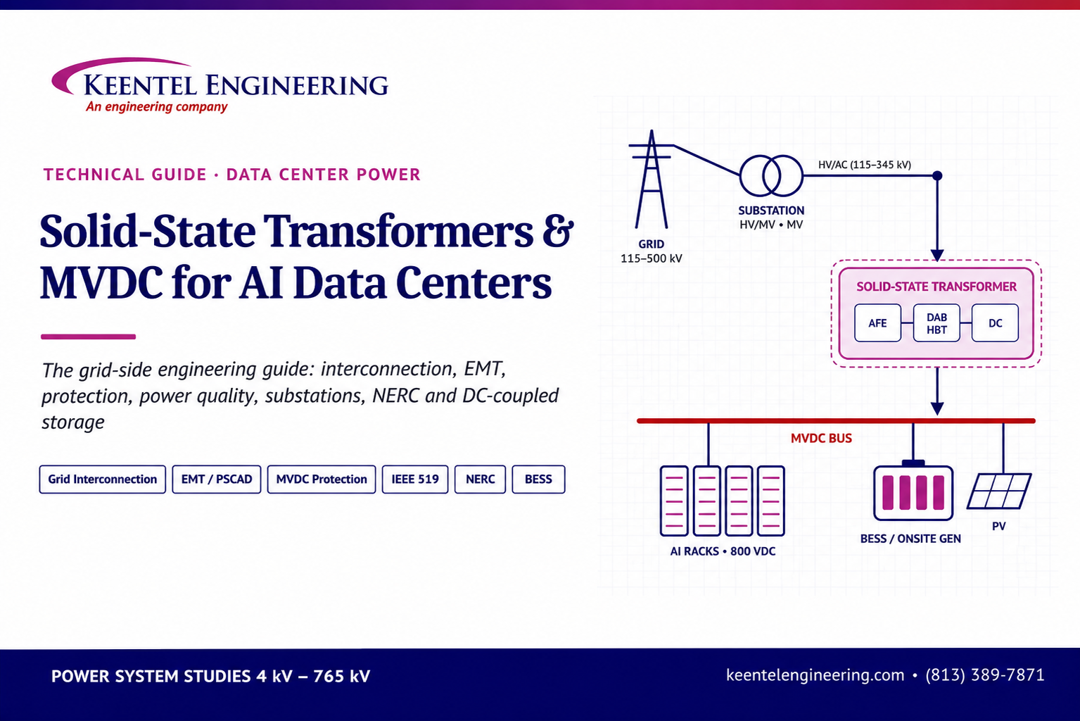
By SANDIP R PATEL
•
November 5, 2026
Explore solid-state transformers and MVDC for AI data centers. Keentel Engineering covers US grid interconnection, EMT modeling and protection studies.
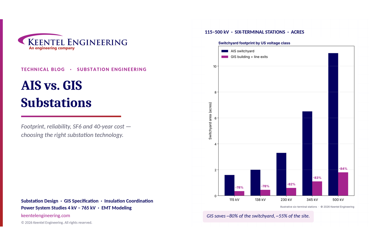
By SANDIP R PATEL
•
October 31, 2026
Compare AIS vs GIS substations by cost, footprint, reliability, maintenance and SF6 impact. Explore design differences and life-cycle costs for US substations.
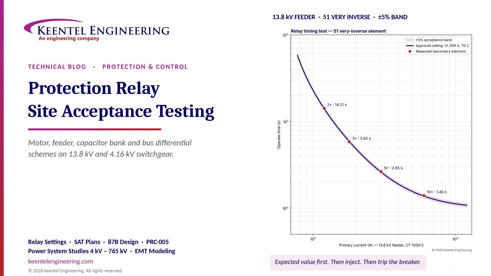
By SANDIP R PATEL
•
October 30, 2026
Protection relay site acceptance testing (SAT) guide covering CT/VT checks, secondary injection, motor relays, 87B bus differential and IEEE/NETA standards.

By SANDIP R PATEL
•
October 30, 2026
Understand SPP HILL requirements, HDPS interconnection studies, voltage and frequency ride-through, EMT modeling, weak-grid screening, and compliance.
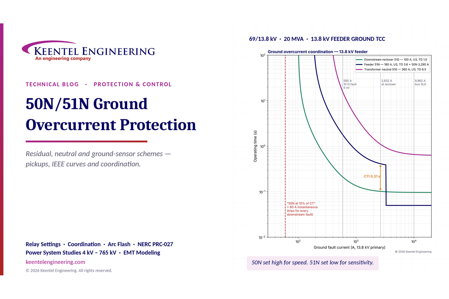
By SANDIP R PATEL
•
October 29, 2026
Learn 50N/51N ground overcurrent protection, relay settings, CT connections, IEEE curves, TCC coordination and ground fault protection for substations.
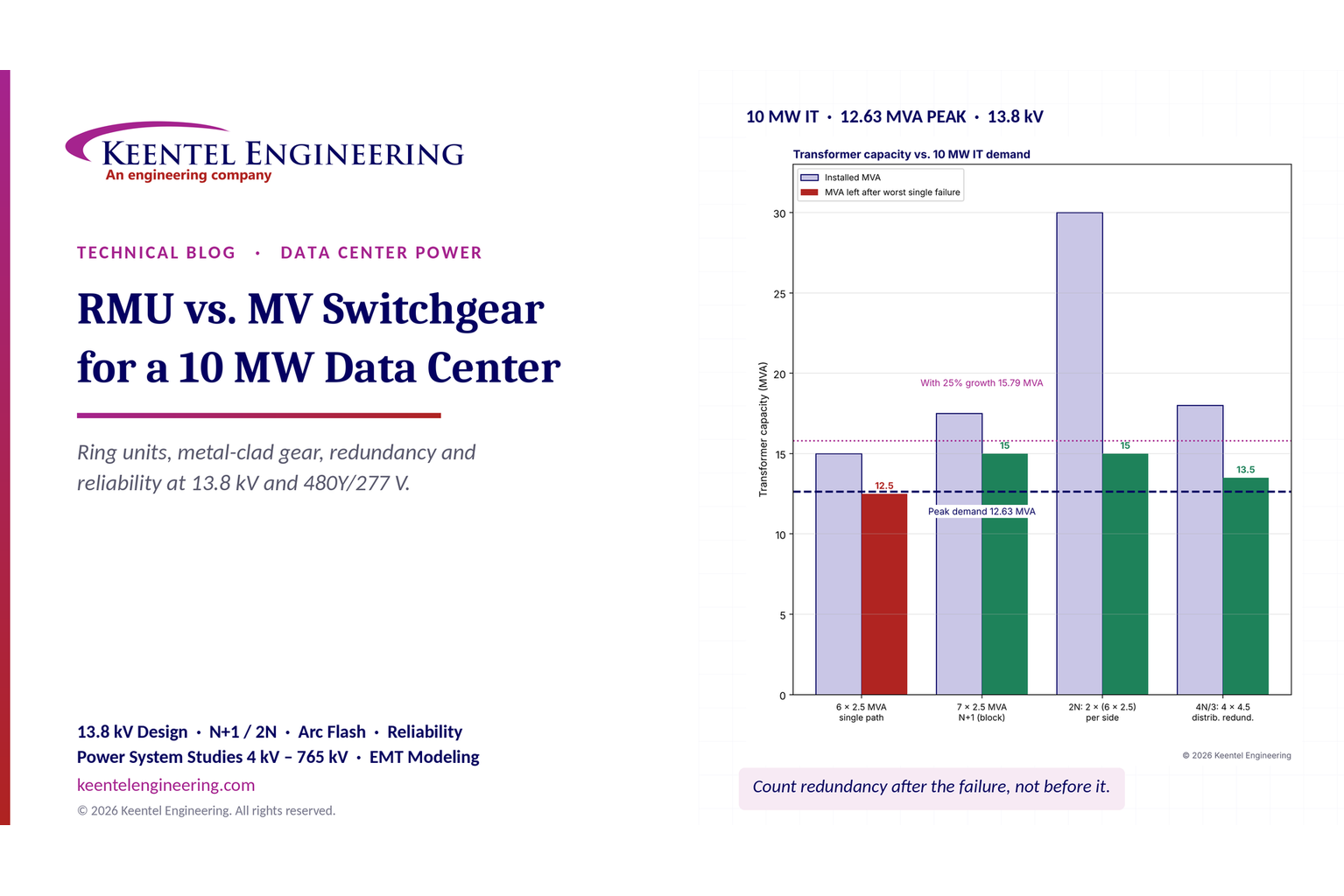
By SANDIP R PATEL
•
October 29, 2026
Compare RMU vs. MV switchgear for a 10 MW data center. Explore 13.8 kV design, transformer sizing, N+1/2N redundancy, arc flash and reliability.
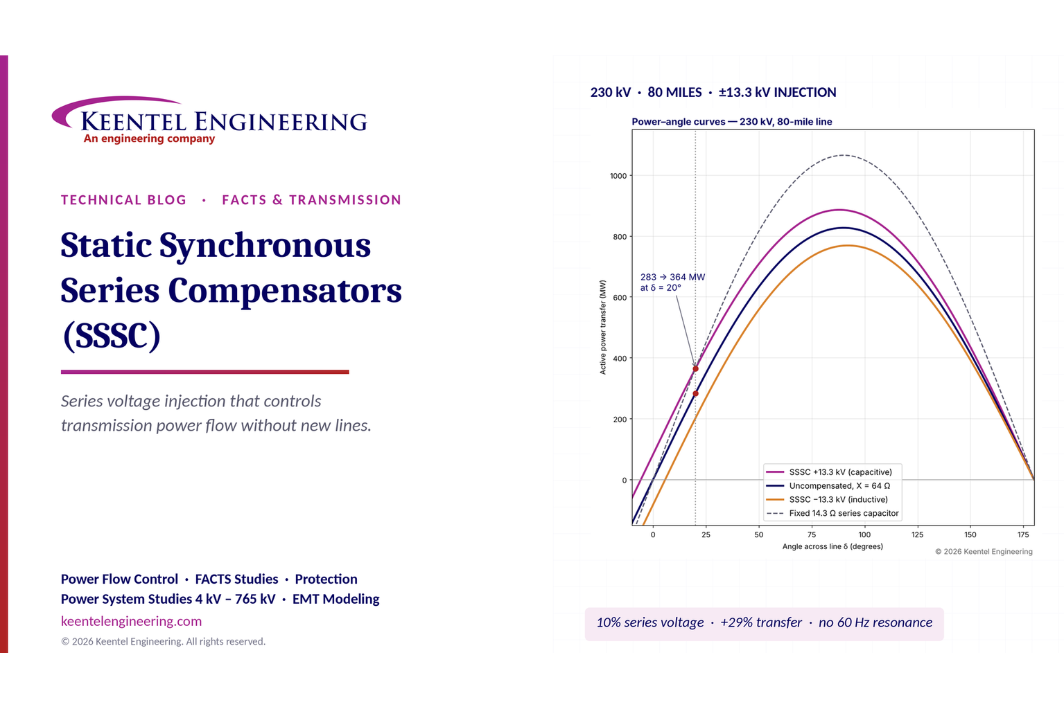
By SANDIP R PATEL
•
October 29, 2026
Learn how static synchronous series compensators (SSSC) control transmission power flow, improve grid stability and support FACTS applications, with examples.

By SANDIP R PATEL
•
October 28, 2026
Explore what's inside a data center rack, from servers and switches to PDU sizing, UPS, A/B redundancy, cooling and power design for high-density AI racks.
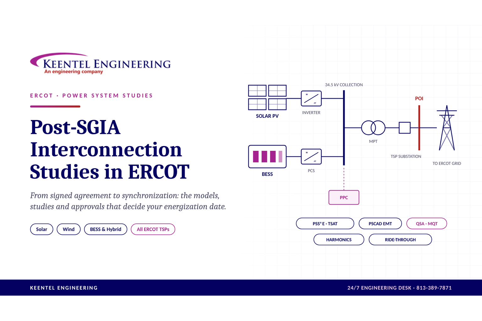
By SANDIP R PATEL
•
October 28, 2026
Explore post-SGIA interconnection studies in ERCOT, including PSCAD, PSS/E, QSA, model validation, TSP approvals and solar, wind and BESS commissioning.