A new medium-voltage switchgear lineup can look finished long before it is safe to energize. The breakers rack in, the doors close and the relay screens light up. But until every protective relay has been proven against its approved settings, through its own current and voltage transformers, all the way to the breaker it is supposed to trip, the protection system is an assumption — not a fact.
Site Acceptance Testing (SAT) is the step that turns that assumption into evidence. This guide explains, from an engineering point of view, how Keentel Engineering plans, performs and documents SAT for a typical 13.8 kV and 4.16 kV industrial or utility switchgear installation with four families of protection:
-
Motor protection — microprocessor motor relays protecting 4.16 kV induction motors (device 49, 46, 47, 27/59, 50/51, 50G/50GS, 37 and trip circuit supervision).
-
Feeder and bay control — bay controllers that combine feeder overcurrent protection with breaker control, interlocking and synchronism check (50/51, 50G/51G, 27/59, 25).
-
Shunt capacitor bank protection — overcurrent, over/undervoltage, ground and unbalance protection (50/51, 27/59, 50G, 60N, 59N).
-
Bus differential protection — high-impedance or low-impedance 87B schemes that clear switchgear bus faults in a few cycles.
The lineup in this guide
Keentel uses one illustrative lineup throughout this article. It represents a common US configuration for a process plant, water/wastewater facility, data center or utility distribution substation.
| Item | Illustrative value |
|---|---|
| Utility supply | 138 kV, stepped down to 13.8 kV by two 30/40/50 MVA transformers |
| 13.8 kV switchgear | Metal-clad (IEEE C37.20.2), main-tie-main, 2000 A bus, 25 kA short-circuit rating, low-resistance grounded (400 A) |
| 4.16 kV switchgear | Metal-clad motor lineup fed by 13.8–4.16 kV transformers, low-resistance grounded (400 A) |
| Protective relays | 28 microprocessor relays: 13 motor relays, 11 bay controllers, 2 capacitor bank relays, 2 bus differential relays |
| Control power | 125 Vdc station battery |
| Frequency | 60 Hz |
What SAT must prove
SAT is not a repeat of the factory test. It answers four field questions that the factory cannot:
| Question | Why the factory test cannot answer it | How SAT answers it |
|---|---|---|
| Are the as-installed settings the approved settings? | Final settings often arrive after factory testing; firmware may change | Download, compare and sign off the settings file against the approved study (checksum or file comparison) |
| Do the elements operate correctly at pickup, dropout and timing? | Factory tests use a generic or interim setting | Secondary injection of every enabled element against the approved settings and published tolerances |
| Are the CT and VT circuits right? | Field wiring, CT taps, polarity and grounding are completed on site | Ratio, polarity, excitation, insulation resistance, burden and primary-injection checks; in-service load checks |
| Does the relay actually trip the right breaker? | The breaker, lockout and interconnecting wiring are not present at the factory | Trip-to-breaker functional tests, lockout (86) checks, interlocks, trip circuit supervision, alarms to SCADA |
What Keentel's analysis shows
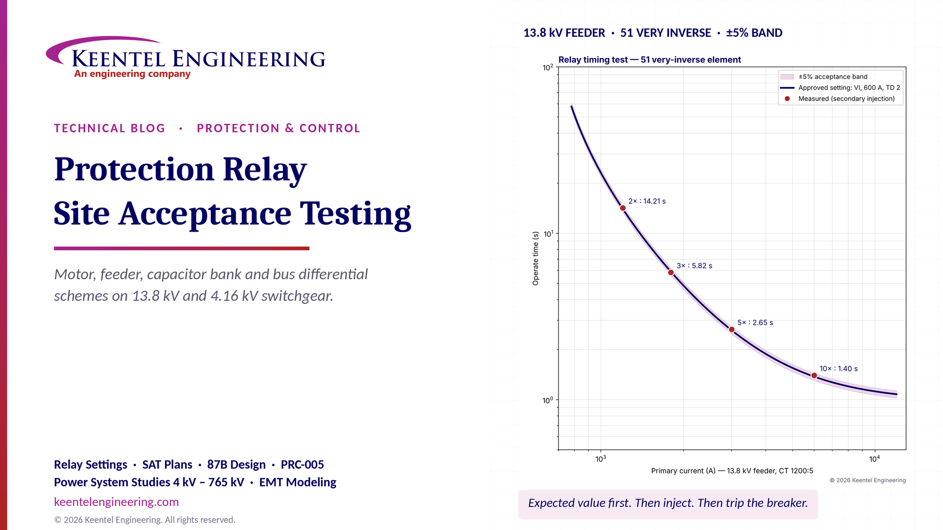
Keentel modeled two of the most common SAT checks: timing of a 51 very-inverse element on a 13.8 kV feeder, and operate/restrain testing of a low-impedance 87B dual-slope characteristic.
| Check | Approved setting | Test result | Verdict |
|---|---|---|---|
| 51 timing at 2× pickup | IEEE very inverse, 600 A primary (2.5 A secondary), time dial 2: 14.06 s expected | 14.21 s (+1.1%) | Pass (±5%) |
| 51 timing at 5× pickup | 2.62 s expected | 2.65 s (+1.3%) | Pass |
| 51 timing at 10× pickup | 1.38 s expected | 1.40 s (+1.7%) | Pass |
| 87B slope 1 at 2 pu restraint | Operate threshold 0.50 pu | Restrains at 0.45 pu, operates at 0.55 pu | Pass |
| 87B slope 2 at 8 pu restraint | Operate threshold 3.75 pu | Restrains at 3.60 pu, operates at 3.90 pu | Pass |
| 87B through-fault stability | 6 pu in, 6 pu out with 0.4 pu simulated CT error | No operation | Pass |
| High-impedance 87B setting | 25 kA through fault, 2000:5 CTs, 1.8 Ω loop | Setting voltage 169 V; knee point must be ≥ 338 V; voltage limiter required | Design check before testing |

Figure 1. Keentel's illustrative SAT results. Left: secondary-injection timing points for a 13.8 kV feeder 51 element plotted against the approved very-inverse curve and a ±5% acceptance band. Right: operate (must-trip) and stability (must-restrain) test points on a low-impedance 87B dual-slope characteristic.
Five lessons
-
Test against the approved settings, not the relay's defaults. Every pickup, dropout and timing result needs an expected value calculated from the approved setting and a written tolerance. A result without an expected value is a reading, not a test.
-
Secondary injection does not prove CT circuits. Injecting at the relay terminals bypasses the CTs, the CT shorting blocks and most of the wiring. Ratio, polarity and grounding must be proven by primary injection, CT tests and in-service load checks.
-
A bus differential relay is only as good as its stability test. The dangerous failure of an 87B scheme is not failing to trip on a bus fault — it is tripping the whole bus for a feeder fault. Prove stability for external faults before enabling the trip.
-
Output contacts are not trip tests. Closing an output contact proves the relay. Opening the breaker proves the protection system. SAT must include the breaker, the lockout relay and the trip circuit.
-
The SAT record is a compliance record. Where the switchgear is part of a Bulk Electric System Protection System, the commissioning test is the first entry in the PRC-005-6 maintenance record. Everywhere else, NFPA 70B and the owner's insurer expect the same discipline.
Engineering review of common statements about relay SAT
| Common statement | Keentel's check |
|---|---|
| "Busbar differential protection was provided by two feeder-management relays." | Possible, but it is worth understanding how. A feeder-class relay usually provides 87B as a high-impedance scheme: the paralleled CT secondaries feed the relay's sensitive overcurrent input through an external stabilizing resistor, with a voltage-limiting resistor (metal-oxide varistor) for internal faults. This is valid and widely used, but the resistor, varistor and CT knee points are part of the scheme and must be tested. US practice more often uses a dedicated high-impedance 87Z relay with a voltage-operated element, or a low-impedance percentage-restraint bus relay. |
| "47 — Phase sequence / voltage unbalance." | Close. IEEE C37.2 defines 47 as a phase-sequence or phase-balance voltage relay. In a motor relay it normally means negative-sequence voltage (V2) or phase reversal. Voltage unbalance on a motor causes a much larger current unbalance (roughly 6 to 10 times), which the 46 element sees. |
| "74TCS — Trip circuit supervision." | Device 74 is an alarm relay in IEEE C37.2. There is no dedicated device number for trip circuit supervision, so drawings use 74TC, TCS or TCM. The important thing is consistency between the drawings, the settings file and the test sheet. |
| "50G/50GS — Ground fault protection." | 50G normally denotes an instantaneous ground element on a ground-sensor (core-balance, zero-sequence) CT; 50N denotes a residual element calculated from the three phase CTs. Some drawings use 50GS for the ground-sensor CT. The difference matters: a ground-sensor CT can only be proven by passing primary current through its window. |
| "Secondary injection testing and pickup/dropout verification." | Necessary but not sufficient. SAT also needs CT and VT verification, primary injection where practical, functional logic testing, trip-to-breaker tests and in-service checks at first energization. |
| "Pickup, dropout, timing and trip verification according to approved settings." | Correct — provided the approved settings are traceable to a signed coordination study and the tolerances are written down before testing starts. |
Part B — Protection Relay Site Acceptance Testing in Technical Depth
1. FAT, SAT and commissioning — three different jobs
Protection testing for new switchgear happens in stages. The names vary by owner and contract, but the engineering purpose of each stage is distinct.
| Stage | Where | What it proves | Typical owner of the test |
|---|---|---|---|
| Factory Acceptance Test (FAT) | Switchgear manufacturer's shop | Wiring matches the drawings; relays power up; basic I/O and control logic; dielectric tests of the assembly per IEEE C37.20.2 | Manufacturer, witnessed by owner or engineer |
| Site Acceptance Test (SAT) | Installed switchgear, de-energized | Every relay, with the approved settings, in the as-installed wiring, operates correctly and trips the correct breaker | Testing contractor (often a NETA-accredited company), reviewed by the engineer of record |
| Energization and in-service checks | Energized system | CT and VT phasing under load, directional and differential quantities, alarms and SCADA points with real power flowing | Testing contractor and owner operations, with engineer support |
| Commissioning (whole-system) | Facility-wide | The integrated system — protection, controls, SCADA, transfer schemes, generators — meets the owner's requirements | Commissioning authority |
SAT sits in the middle and carries the most risk. It is the last chance to find an error while the equipment is still dead and the consequences of a mistake are a failed test rather than a damaged motor or a plant-wide outage.
1.1 Why the factory test is not enough
A FAT is valuable, but four things change between the factory and the site:
-
Settings. The final coordination study is often completed after the switchgear is built. The relays leave the factory with interim or default settings.
-
Field wiring. CT secondaries from transformers, cable-mounted ground-sensor CTs, VT connections, interposing wiring to motor starters, and trip and close circuits to remote equipment are completed in the field.
-
Shipping splits. Multi-section lineups ship in splits and are re-joined on site. Bus wiring, CT shorting links and control wiring across the splits are common error points.
-
Firmware and configuration. Relays may be updated after the FAT, and logic, communications and IEC 61850 configurations may be finalized on site.
1.2 The standards that frame SAT in the US
| Document | What it contributes to SAT |
|---|---|
| ANSI/NETA ATS — Standard for Acceptance Testing Specifications for Electrical Power Equipment and Systems (current edition) | Test lists and acceptance criteria for protective relays, instrument transformers, metal-clad switchgear, circuit breakers, batteries and grounding. The most commonly specified SAT standard in US contracts. |
| ANSI/NETA MTS — Maintenance Testing Specifications | The maintenance counterpart; useful for setting the baseline that future tests will repeat. |
| ANSI/NETA ECS — Standard for Commissioning Electrical Systems | System-level commissioning beyond individual component tests. |
| IEEE C37.2 | Device function numbers and suffixes used on drawings and settings. |
| IEEE C37.233 | Guide for power system protection testing — test types, test planning and documentation. |
| IEEE C37.103 | Guide for differential and polarity relay circuit testing — the reference for in-service phasing and differential checks. |
| IEEE C37.96, C37.99, C37.234, C37.230 | Application guides for motor, shunt capacitor, bus and distribution feeder protection — the source of the settings philosophy being tested. |
| IEEE C37.112 | Inverse-time overcurrent characteristic equations used to calculate expected trip times. |
| IEEE C57.13 and C37.110 | CT accuracy classes, testing, and application to relaying. |
| IEEE C37.20.2 | Metal-clad switchgear ratings and tests. |
| NFPA 70E and IEEE 1584 | Electrical safety in the workplace and arc-flash incident energy calculation for work on or near energized equipment. |
| NFPA 70B | Electrical equipment maintenance — now a standard, establishing baseline testing and maintenance programs. |
| NERC PRC-005-6 | Protection System maintenance for Bulk Electric System elements, where applicable. |
2. Device numbers — reading the scheme correctly
Every SAT test sheet starts with a list of enabled functions. Getting the device numbers right is not pedantry: a misread function becomes a missed test. The table below gives the IEEE C37.2 meaning and the practical SAT note for each function in our lineup.
| Device | IEEE C37.2 meaning | Where it appears | SAT note |
|---|---|---|---|
| 25 | Synchronizing or synchronism-check device | Bay controllers on ties and incomers | Test voltage, frequency (slip) and angle windows; dead-bus/dead-line logic; close supervision of manual and automatic close |
| 27 | Undervoltage relay | Motors, buses, capacitor banks | Test pickup, dropout and time; confirm VT fuse-failure supervision blocks it where intended |
| 37 | Undercurrent or underpower relay | Motors (loss of load, pump running dry) | Test pickup and time; confirm it is blocked when the motor is stopped |
| 46 | Reverse-phase or phase-balance current relay | Motors | Usually negative-sequence current (I2) or percent unbalance; test definite and inverse elements |
| 47 | Phase-sequence or phase-balance voltage relay | Motors, buses | Test phase reversal and negative-sequence voltage (V2) pickup |
| 49 | Machine or transformer thermal relay | Motors | Test the thermal model trip time from cold and from a known thermal state; verify reset and start inhibit |
| 50 | Instantaneous overcurrent relay | All | Test pickup and operating time; confirm it is above motor inrush or transformer magnetizing current |
| 51 | AC inverse-time overcurrent relay | All | Test pickup, dropout and timing at several multiples against the C37.112 equation |
| 50G / 51G | Instantaneous / time ground overcurrent (ground-sensor or neutral CT) | Motors, feeders | Prove the ground-sensor CT by primary injection through the window |
| 50N / 51N | Instantaneous / time residual (neutral) overcurrent | Feeders | Residual sum of phase CTs; prove by single-phase injection and by load checks |
| 59 | Overvoltage relay | Motors, buses, capacitor banks | Test pickup, dropout and time |
| 59N | Neutral overvoltage | Ungrounded capacitor banks; ungrounded or high-resistance grounded systems | Test with the neutral VT or broken-delta input; verify unbalance compensation |
| 60 / 60N | Voltage or current balance relay; neutral current unbalance | Capacitor banks | Test pickup, time, alarm and trip stages; verify inherent-unbalance compensation |
| 74 | Alarm relay | Trip circuit supervision, often written 74TC | Test with breaker open and closed; open the trip circuit to prove the alarm |
| 86 | Lockout relay | Bus differential, transformer and motor schemes | Prove trip of every breaker, close blocking and manual reset |
| 87B | Bus differential relay | 13.8 kV bus | Stability (external fault) and operate (internal fault) tests, CT circuit supervision, zone selection |
3. Test equipment, safety and preparation
3.1 The test set
A modern three-phase relay test set provides at least three current and three voltage sources, binary inputs to time relay outputs, binary outputs to simulate breaker status, and software that runs automated test plans. For SAT on medium-voltage switchgear, check four capabilities before mobilizing:
-
Current magnitude. Instantaneous and high-multiple timing tests can need 30 to 60 A secondary per phase. A 5 A relay set with a 51 pickup of 2.5 A requires 25 A at 10× pickup.
-
Compliance voltage. The test set must drive the current through the relay burden and the test leads. High-impedance differential tests need hundreds of volts.
-
Timing accuracy. Timing to better than 1 ms is normal; the relay tolerance is the limiting factor.
-
Synchronized injection. End-to-end and some logic tests need GPS-synchronized test sets.
A calibrated digital multimeter, a clamp-on ammeter, a phase-angle meter, a CT analyzer or CT excitation test set, a primary-injection set and an insulation resistance tester complete the kit. Every instrument must have a current calibration certificate, and the certificate number belongs on the test sheet.
3.2 Electrical safety
Switchgear SAT is often performed while adjacent equipment is energized, or while temporary power feeds part of the lineup. Keentel's planning requirements:
-
Energized work assessment. Every task is assessed under NFPA 70E for shock and arc-flash risk. Incident energy at each work location comes from the IEEE 1584 arc-flash study.
-
Isolation of CT circuits. Never open-circuit a CT secondary on an energized primary. Use test switches or shorting blocks; verify the short with a clamp-on meter before lifting any wire.
-
Isolation of trip circuits. Before secondary injection, isolate trip outputs to breakers that are in service, or confirm the breakers are racked to the test position. Accidental trips during SAT are a leading cause of commissioning outages.
-
VT circuits. Isolate VT secondaries before injecting voltage to prevent back-feeding a VT to primary voltage. A 120 V injection into a 4200:120 VT secondary appears as 4.2 kV on the primary.
-
Lockout/tagout. Applies to every breaker cubicle and every source, including control power and temporary generators.
3.3 Paperwork before tools
A SAT is only as good as the documents it is tested against. Before testing starts, Keentel confirms that the following are issued and controlled:
| Document | Purpose in SAT |
|---|---|
| Approved protective device coordination study and settings | The expected values for every test |
| Relay settings files, with revision and date | What is loaded in each relay |
| Three-line diagrams, AC and DC schematics, wiring diagrams | Test points, CT and VT connections, trip paths |
| CT and VT nameplate data and test reports | Ratios, accuracy classes, polarity, excitation curves |
| Logic diagrams and IEC 61850 configuration files | Expected behavior of interlocks and GOOSE messages |
| Test plan and test sheets with tolerances | Acceptance criteria written before the test |
| Manufacturer's instruction manuals and published accuracy | Basis for tolerances |
4. Instrument transformer verification — the foundation of the scheme
A relay that operates perfectly with test-set current can still fail in service if its CTs are wrong. More SAT findings come from instrument transformer circuits than from relays.
4.1 CT tests
| Test | Method | What it catches | Typical acceptance |
|---|---|---|---|
| Ratio | Primary injection or voltage-method ratio test with a CT analyzer | Wrong tap on a multi-ratio CT; wrong CT installed | Within the C57.13 accuracy class; consistent with nameplate |
| Polarity | Primary injection, CT analyzer or flick test | Reversed CT — fatal to differential and directional elements | Matches the three-line diagram |
| Excitation (saturation) curve | Apply increasing secondary voltage and record excitation current | Shorted turns, wrong accuracy class, knee point too low for the application | Within the manufacturer's published curve; knee point recorded |
| Winding resistance | DC resistance of the secondary | Loose connections; needed for burden and differential calculations | Consistent with manufacturer's data |
| Insulation resistance | Secondary-to-ground at 500 or 1000 Vdc | Damaged wiring and terminals | Per NETA ATS tables |
| Burden | Measure the loop impedance of the CT secondary circuit | High-resistance connections, long leads, extra devices in the circuit | Below the CT rated burden with margin |
| Single-point grounding | Lift the ground and confirm loss of continuity; inspect | Multiple grounds (circulating currents) or no ground | One ground per circuit, at the location shown on the drawings |
4.2 Worked example — will the feeder CT saturate?
A 13.8 kV feeder uses a 1200:5 multi-ratio CT, class C400, on the full 1200:5 tap. The maximum fault current at the switchgear is 25 kA, with an X/R ratio of 15. The secondary circuit has 0.48 Ω CT winding resistance, 0.40 Ω of lead resistance (round trip) and a negligible relay burden of 0.02 Ω.
The secondary fault current is:

The total burden is 0.90 Ω. The symmetrical voltage the CT must produce is:

That is well below the C400 rating, so the CT will not saturate on the symmetrical current. But IEEE C37.110 provides a criterion to avoid saturation with full DC offset:

where If is the fault current in per unit of CT rated current and Zb is the burden in per unit of the standard burden for the accuracy class (4 Ω for C400). Here Zb = 0.90 / 4 = 0.225 pu:

The CT will saturate for the first cycles of a fully offset fault. For a 51 element this is usually acceptable — the relay sees reduced current briefly and trips slightly later. For an instantaneous element it may delay operation by a cycle or so. For a bus differential scheme, it is exactly the condition the stability design must survive. The SAT team should record measured winding resistance and lead resistance so the engineer can confirm these calculations with field values.
4.3 VT tests
VT checks include ratio and polarity, secondary insulation resistance, fuse and fuse-holder inspection, and a phasing check at first energization. A common SAT failure is a VT secondary grounded in two places, or a broken-delta winding wired with one winding reversed — which gives a large standing residual voltage and a nuisance 59N alarm.
4.4 Primary injection
Primary injection drives a high current (hundreds to thousands of amperes) through the primary conductor of a CT and measures the response at the relay. It proves the CT, its ratio and polarity, the shorting blocks, the wiring and the relay measurement in one test. For ground-sensor (zero-sequence) CTs on motor and feeder cables, primary injection through the window is the only practical way to prove the CT before energization.
Keentel practice: For every ground-sensor CT, pass a single test conductor through the window, inject the 50G pickup current, and confirm the relay reads it. Then confirm the cable shield drain wires are routed correctly — back through the window if the shield is grounded on the load side of the CT — so that shield currents cancel.
4.5 In-service checks at energization
When the switchgear is energized and carries load, the testing team reads magnitudes and angles of every current and voltage at the relay. These checks are the final proof that phasing, ratio and polarity are right:
-
Phase currents balanced and at 120° spacing, in the correct sequence (ABC or ACB, as the system uses).
-
Phase current angle relative to voltage consistent with the expected power factor.
-
Residual current near zero with balanced load.
-
For differential schemes, operate current near zero and restraint current consistent with load.
-
Negative-sequence quantities small.
IEEE C37.103 describes these checks in detail. They are fast, and they catch errors that no de-energized test can.
5. Overcurrent testing — pickup, dropout and timing
Overcurrent elements appear in every relay in the lineup, so their test method sets the pattern for the rest of the SAT.
5.1 Pickup and dropout
Pickup is the smallest current that causes the element to start timing (or operate, for an instantaneous element). Dropout is the current at which it resets. They are measured by ramping the current slowly — in small steps held long enough for the relay to respond — up through pickup and back down through dropout.
The dropout ratio is:

Microprocessor relays typically have dropout ratios of 95% to 98%. A low dropout ratio matters for coordination: if a feeder element picks up on a fault and the fault is cleared downstream, the element must reset when current returns to load level.
Worked example. A 13.8 kV feeder 51 element is set at 600 A primary on a 1200:5 CT, so the secondary pickup is 600 / 240 = 2.50 A. The test records a pickup of 2.49 A and a dropout of 2.38 A.


Both are within a typical published accuracy of ±2% to ±5% of setting. The result is a pass — but only because the expected value (2.50 A) and the tolerance were written on the test sheet before the test.
5.2 Inverse-time characteristics
IEEE C37.112 defines inverse-time overcurrent curves by the equation:

where M is the multiple of pickup current, TD is the time dial and A, B and p are curve constants.
| Curve (IEEE C37.112) | A | B | p |
|---|---|---|---|
| Moderately inverse | 0.0515 | 0.1140 | 0.02 |
| Very inverse | 19.61 | 0.491 | 2.0 |
| Extremely inverse | 28.2 | 0.1217 | 2.0 |
Relay manufacturers implement these curves with their own labels (for example "U1" to "U5") and sometimes with their own time-dial scaling. Before calculating expected times, confirm from the relay manual which equation and which time-dial convention the relay uses. A curve label that looks the same on two relay brands may not give the same time.
Worked example. The feeder element uses the IEEE very-inverse curve with TD = 2. Expected times are:
| Multiple of pickup M | Secondary test current | Expected time (s) | ±5% band (s) | Measured (s) | Error | Result |
|---|---|---|---|---|---|---|
| 2 | 5.0 A | 14.06 | 13.35 – 14.76 | 14.21 | +1.1% | Pass |
| 3 | 7.5 A | 5.88 | 5.59 – 6.18 | 5.82 | −1.1% | Pass |
| 5 | 12.5 A | 2.62 | 2.49 – 2.75 | 2.65 | +1.3% | Pass |
| 10 | 25.0 A | 1.38 | 1.31 – 1.45 | 1.40 | +1.7% | Pass |
For example, at M = 5:

Typical published timing accuracy is the greater of a percentage (often ±3% to ±5%) and a fixed time (often 1 to 1.5 cycles). At low multiples the percentage governs; on fast instantaneous elements the fixed time governs.
Keentel practice: Test timing at a minimum of three multiples (for example 2×, 5× and 10× pickup) plus any point where the coordination study has a critical margin. If the study shows only 0.25 s between this element and an upstream breaker at the maximum fault level, that fault level is a test point.
5.3 Instantaneous elements
Instantaneous elements (50) are tested for pickup at a current slightly below and slightly above setting, and for operating time at around 1.2× to 2× pickup. Operating time for a microprocessor relay is typically one cycle or less, plus the output contact time. If a definite-time delay is applied (sometimes written 50/62 or 50 with a time setting), test the delay as a separate timing value.
5.4 Thermal limits of the relay input
High-multiple tests stress the relay current inputs. A 5 A input is typically rated for about 15 A continuous and 100 A for one second. A test at 25 A held for 1.4 s is within those limits, but a test at 50 A held for several seconds may not be. Read the input ratings and keep high-current injections short.
6. Motor protection — the 4.16 kV motor relay
The motor relays in our lineup protect 4.16 kV induction motors driving pumps and fans. The largest is a 1,500 hp motor. Motor protection is more than overcurrent: the relay models the motor's heating, watches for unbalance, recognizes starting and stalling, and blocks restarts that would overheat the rotor.
6.1 Motor data
| Item | Value |
|---|---|
| Rating | 1,500 hp, 4,000 V nameplate (on a 4.16 kV system), 1,800 rpm |
| Efficiency and power factor at full load | 95%, 0.89 |
| Full-load current (FLA), calculated at 4.16 kV | about 184 A |
| Service factor | 1.15 |
| Locked-rotor current | 6.0 × FLA = about 1,104 A |
| Safe stall time (hot / cold) | 12 s / 16 s |
| Phase CTs | 300:5 |
| Ground-sensor CT | 50:5 window type |
Full-load current is calculated as:

On the 300:5 CT, the relay sees 184 / 60 = 3.06 A secondary at full load. This value (or the nameplate FLA, where the settings use it) — not the CT rating — is the base for the relay's per-unit settings. Entering the wrong FLA or CT ratio is one of the most frequent motor relay setting errors found at SAT.
6.2 Thermal overload (49)
Most motor relays use a thermal model rather than a simple inverse-time curve. A common first-order form of the trip time is:

where τ is the heating time constant, I is the test current in per unit of FLA, Ip is the prior (pre-load) current in per unit and k is the overload pickup factor (often the service factor, 1.15). Relays differ in how they implement the model — some use the IEC-style equation above, some use a family of curves, and many include a separate rotor model for starting — so the expected times must come from the manufacturer's equation for that relay.
Worked example. With τ = 30 minutes (1,800 s) and k = 1.15:
| Test current (× FLA) | Prior state | Expected trip time |
|---|---|---|
| 2.0 | Cold (Ip = 0) | 1,800 × ln(4 / 2.678) = 723 s |
| 2.0 | Hot (Ip = 1.0) | 1,800 × ln(3 / 2.678) = 205 s |
| 3.0 | Cold | 286 s |
| 3.0 | Hot | 74 s |
| 6.0 | Cold | 67 s |
| 6.0 | Hot | 17 s |
Two practical points follow. First, thermal tests are long; a cold test at 2× FLA takes twelve minutes, so plan the test schedule. Second, the "hot" state must be created deliberately — by injecting rated current until the thermal capacity used reaches a steady value, or by using the relay's test mode to preset thermal capacity. Record which method was used. Also verify that the thermal model's cooling time constants (running and stopped) and the start-inhibit logic match the settings.
Note also that the hot locked-rotor trip time (17 s in this simple model) exceeds the hot safe stall time of 12 s. That is why motor relays include separate stall and acceleration protection — a definite-time or speed-switch-supervised element — rather than relying on the thermal model alone. SAT should test that element too.
6.3 Current unbalance and negative sequence (46)
Unbalanced supply voltage creates negative-sequence current, which induces double-frequency currents in the rotor and heats it far more than the same positive-sequence current would. A 1% voltage unbalance can produce roughly 6% to 10% current unbalance in an induction motor.
The negative-sequence current is calculated from the phase currents:

For the worst case — an open phase on a running motor — Ia = 0 and Ib = −Ic, so:

The relay sees 100% unbalance (I2/I1 = 1). That is the single-phasing condition the 46 element must trip quickly.
Many relays use an inverse-time negative-sequence element of the form:

With K = 20 and an injected I2 of 0.5 pu, the expected time is 20 / 0.25 = 80 s. SAT tests the alarm and trip pickups and at least two timing points, by injecting balanced three-phase current with one phase angle or magnitude changed to produce a known I2. Calculate the expected I2 for the exact injected currents rather than assuming it.
6.4 Phase sequence and voltage balance (47)
The 47 element in a motor relay usually trips or blocks starting on phase reversal and on negative-sequence voltage above a setting (often 5% to 10% V2). Test by injecting balanced voltages in the reverse sequence (swap B and C) and by injecting a known V2. On a 4200:120 VT, 5% V2 corresponds to about 3.5 V secondary phase-to-neutral (5% of 69.3 V).
6.5 Under- and overvoltage (27/59)
On the 4200:120 VT, an 80% undervoltage setting is 96 V phase-to-phase and a 110% overvoltage setting is 132 V. Test pickup, dropout and time for each. Confirm whether the element uses phase-to-phase or phase-to-neutral voltage and whether it needs one, two or all three phases to operate — that logic changes the test.
6.6 Short circuit (50) and locked rotor
The instantaneous element must not trip on motor starting inrush. A typical setting rule is 1.6 to 2.0 times the symmetrical locked-rotor current, to allow for the asymmetrical first-cycle current. With 1,104 A locked-rotor current and a factor of 1.7:

Testing at 1.2 × pickup requires about 38 A secondary — check that the test set can deliver it on a single phase, or parallel current channels. For vacuum-contactor (fused) starters, confirm that the relay does not trip the contactor for currents above the contactor's interrupting rating; that logic is a common SAT test item on 4.16 kV motor starters.
6.7 Ground fault (50G) on a ground-sensor CT
On a 400 A low-resistance grounded 4.16 kV system, motor ground-fault pickups are typically set at 5 to 20 A primary. With a 50:5 ground-sensor CT and a 10 A primary setting, the relay pickup is 1.0 A secondary. Secondary injection tests the relay. Primary injection through the CT window proves the CT, its ratio and the routing of the cable shields.
6.8 Undercurrent (37)
Loss-of-load protection for a pump might be set at 40% FLA (about 1.22 A secondary) with a 10 s delay. Confirm that the element is blocked when the motor is stopped (otherwise it trips every stopped motor) and is only armed after the motor is running.
6.9 Starting, acceleration and restart logic
Test the start detection (current rising above a threshold), the acceleration timer, the number of starts per hour, the time between starts and the restart inhibit based on thermal capacity. These are control and protection functions together, and they are often where field logic errors hide.
7. Bay controllers — feeder protection, control and synchronism check
Bay controllers combine protection (50/51, 50N/51N, 50G/51G, 27/59) with breaker control, interlocking, metering and communications. Their SAT therefore has two halves: protection tests like those above, and functional tests of control logic.
7.1 Control and interlocking
The functional test list typically includes:
-
Local and remote open and close, with the local/remote selector.
-
Breaker position indication (52a/52b) and racked-in/test position inputs.
-
Interlocks: main-tie-main logic, closing blocked by lockout (86), closing blocked by a racked-out or earthed position.
-
Automatic transfer logic, if present, including the transfer timing.
-
Alarm and event reporting to SCADA, checked point by point.
7.2 Synchronism check (25)
Synchronism check permits closing only when the voltages on the two sides of the breaker are close enough in magnitude, frequency and phase. Typical settings for a 13.8 kV tie breaker:
| Parameter | Typical setting |
|---|---|
| Voltage difference ΔV | ≤ 5% |
| Slip frequency Δf | ≤ 0.1 Hz (often 0.05 to 0.2 Hz) |
| Phase angle difference Δθ | ≤ 20° |
| Live/dead thresholds | Live above 80% V; dead below 30% V |
When the two systems are slipping, the phase angle sweeps through the window. The slip period and time inside a ±20° window are:

If the controller issues a close command at the edge of the window, the breaker's closing time causes the angle to change before the contacts touch. The advance angle is:

for a 5-cycle (83 ms) breaker. At 0.1 Hz this is small, which is why simple sync-check relays (supervising a manual close) work well. For automatic synchronizing of generators at higher slip, advance-angle compensation matters.
SAT for the 25 element injects two voltages from the test set — bus and line — and tests each boundary: voltage difference, slip frequency and angle, plus the dead-bus/live-line, live-bus/dead-line and dead-dead permissive combinations. Then a functional close is made with the breaker in the test position, confirming the close is blocked outside the window and permitted inside it.
7.3 Residual and ground elements
For residual elements (50N/51N), inject current in one phase only and confirm the residual pickup. Then inject balanced three-phase current above the phase pickup and confirm the residual element does not operate — a simple check that catches a phase CT input wired with the wrong polarity in the relay configuration.
8. Shunt capacitor bank protection
Capacitor banks on the 13.8 kV bus correct power factor and support voltage. Their protection has a feature that no other scheme in the lineup has: it must detect the failure of a single capacitor unit — a few percent change in impedance — long before the bank's phase currents look abnormal. That is the job of the unbalance elements (60N and 59N). IEEE C37.99 is the application guide.
8.1 The bank
| Item | Value |
|---|---|
| Rating | 3.6 Mvar, 13.8 kV, three-phase |
| Configuration | Ungrounded split wye, neutrals tied through a current transformer (neutral CT 25:5) |
| Each half-phase | One series group of three 200 kvar, 7.96 kV externally fused units in parallel |
| Unit reactance | Xu = V² / Q = 7,967² / 200,000 = 317.4 Ω |
| Healthy half-phase current | 75.3 A (phase current 150.6 A) |
8.2 Phase elements
-
50/51 protects against bus and major internal faults. The 51 pickup is set above the bank's maximum continuous current — typically 1.25 to 1.35 times rated, allowing for overvoltage and harmonics — and the 50 element above energizing inrush. Test them as described in Section 5.
-
59 protects the units from sustained overvoltage. Capacitors are rated for 110% of rated rms voltage continuously, and for short-time overvoltages per IEEE 18. Test pickup and time.
-
27 trips the bank on loss of bus voltage so that it is not re-energized with trapped charge when the bus returns. The capacitor must discharge before reclosing — IEEE 18 requires an internal discharge device that reduces residual voltage to 50 V or less within 5 minutes for units above 600 V. The 27 trip and the close-inhibit timer are therefore both test items.
-
50G/51G detects ground faults. On an ungrounded wye bank, a ground fault within the bank is detected at the bus or feeder ground element; confirm with the study which element is intended.
8.3 Neutral current unbalance (60N) — worked example
With the neutrals of the two wyes tied together through a CT, a healthy bank carries almost no neutral current. When a unit fuse operates, the impedance of that half-phase rises and current flows between the neutrals.
Keentel's network calculation for the bank above gives:
| Condition | Half-phase impedance | Neutral current (primary) | Neutral current (secondary, 25:5) | Voltage on remaining units in the affected group |
|---|---|---|---|---|
| Healthy | 105.8 Ω | ≈ 0 A (inherent unbalance only) | ≈ 0 A | 100% |
| One fuse operated | 158.7 Ω | 13.3 A | 2.66 A | 105.9% |
| Two fuses operated | 317.4 Ω | 28.2 A | 5.65 A | 112.5% |
The voltage on the remaining units sets the strategy. With one fuse operated, the surviving units see 105.9% voltage — below the 110% continuous limit — so the bank may stay in service with an alarm. With two fuses operated, they see 112.5%, which exceeds the limit, so the bank must trip.
Settings follow:
-
Alarm at about half the one-fuse signal: 1.3 A secondary, with a delay of about 10 s.
-
Trip between the one-fuse and two-fuse signals: about 4.1 A secondary, with a short delay (for example 0.5 s) to ride through switching transients.
SAT tests both stages for pickup and timing by secondary injection into the neutral CT input. It also proves the neutral CT by primary injection: a test current passed through the neutral connection should appear at the relay at the 25:5 ratio.
Inherent unbalance: Manufacturing tolerances mean that a new bank has a small standing neutral current — often comparable to a large fraction of the one-fuse signal in big banks with many units. Modern relays measure and compensate for it. Compensation must be performed after energization, with the bank healthy, and the compensated value recorded. That is an in-service SAT step, not a de-energized one.
8.4 Neutral voltage unbalance (59N)
For a single ungrounded wye bank, the equivalent quantity is the neutral-to-ground voltage. For the same 3.6 Mvar bank built as a single wye with six units per phase:
| Condition | Neutral voltage (primary) | % of phase voltage | Secondary on a 70:1 neutral VT |
|---|---|---|---|
| One fuse operated | 469 V | 5.9% | 6.7 V |
| Two fuses operated | 996 V | 12.5% | 14.2 V |
Here the relay must also distinguish bank unbalance from system voltage unbalance: zero-sequence voltage on the bus also appears at an ungrounded wye neutral. Relays that compensate by measuring bus V0 (or that use a voltage-differential method) must have that compensation tested with unbalanced bus voltages injected.
9. Bus differential protection (87B)
A fault on a 13.8 kV switchgear bus with 25 kA available can destroy the lineup in a few tenths of a second. Bus differential protection clears it in roughly 1 to 1.5 cycles of relay time plus breaker time — about 6 to 7 cycles total — instead of the 0.4 to 1.0 s a coordinated incomer 51 element would need. That speed is also the most effective arc-energy reduction available on medium-voltage switchgear (Section 12).
The principle is simple — by Kirchhoff's current law, the currents into a healthy bus sum to zero — but the engineering is about what happens when CTs saturate during external faults. A feeder fault fed by 25 kA through the bus forces the feeder CT to carry the full fault current while each source CT carries part of it. If the feeder CT saturates, the relay sees a false difference current. The scheme must stay stable for that.
There are two families of bus differential schemes.
9.1 High-impedance bus differential
All CTs in the zone are paralleled at a common junction and connected to a relay branch with a high impedance. During an external fault with one CT completely saturated, the saturated CT behaves as a low resistance (its winding and lead resistance), so the healthy CTs' current mostly circulates through it rather than through the high-impedance relay. The voltage across the relay is limited to the voltage drop across the saturated CT's loop. Setting the relay above that voltage makes it stable.
The minimum setting voltage is:

where IF,max is the maximum external through-fault current, N is the CT ratio, RCT is the CT secondary winding resistance, RL is the one-way lead resistance from the CT to the junction, and K is a safety factor (often 1.5 to 2, or as specified by the relay manufacturer).
Worked example. The 13.8 kV bus has 2000:5 class C400 CTs (N = 400) on all eight circuits (two incomers and six feeders). The measured CT winding resistance is 0.8 Ω and the worst one-way lead resistance is 0.5 Ω. The maximum through-fault current is 25 kA. With K = 1.5:

Keentel would set 170 V. The CT knee-point voltage should be at least twice the setting voltage so that the CTs drive enough current into the relay for internal faults:

The measured knee points (ANSI 45° tangent method) of all eight CTs must be checked against this. In Keentel's example the measured knee points range from 350 V to 420 V, so the scheme passes — but with little margin on the weakest CT. A CT with a low knee point — wrong class, or connected on a lower tap — can fail the criterion even though its nameplate looks correct.
Using a feeder-class relay as the 87B element. Many schemes, especially those built to international practice, use a sensitive overcurrent input of a feeder relay in series with an external stabilizing resistor. If the relay current setting is Is = 0.10 A, the stabilizing resistor is:

The primary operating current (the smallest bus fault that trips) includes the relay current, the magnetizing current of every CT at the setting voltage, and the leakage current of the voltage limiter:

With n = 8 CTs, each drawing 0.02 A at 170 V, and 0.005 A of limiter leakage:

The smallest bus fault on this 400 A low-resistance grounded system is a ground fault of up to 400 A, so 106 A gives the scheme good sensitivity (about 27% of the minimum fault).
Voltage limiter. For a maximum internal fault, the CTs try to drive the full secondary current through the 1,700 Ω branch. The theoretical voltage is enormous:

The CTs saturate, but the peak voltage still reaches approximately:

This exceeds the 3 kV level commonly used as the limit for secondary wiring and relay insulation, so a non-linear voltage-limiting resistor (a metal-oxide or silicon-carbide varistor) is required across the relay branch. In US practice, dedicated high-impedance bus relays usually include a voltage-operated element and a built-in limiter; when the 87B is built from a feeder relay, the resistor and limiter are separate components, and they are part of the protection system to be tested.
SAT for a high-impedance scheme:
| Test | Purpose |
|---|---|
| CT excitation curves for every CT in the zone | Confirm knee points ≥ 2 VS and matching characteristics |
| CT winding and lead resistance | Confirm the RCT + 2RL used in the setting |
| Stabilizing resistor value and thermal rating | Confirm Rst and that it survives an internal fault until cleared |
| Voltage limiter characteristic | Confirm leakage at VS and clamping behavior per the manufacturer |
| Secondary injection of the relay branch (voltage or current) | Confirm the operating voltage, pickup and time |
| Primary injection, through-fault: inject in through one CT and out through another | Spill current near zero — proves ratio and polarity for each pair |
| Primary injection, internal fault: inject through one CT only | Relay operates at the expected primary operating current |
| CT supervision (bus-wire supervision) element | Alarms and, where designed, shorts the bus wires for an open CT |
| Lockout relay (86B) trips every breaker in the zone | Proves the trip paths |
The CT supervision point is important. An open CT circuit on a loaded feeder forces that feeder's secondary load current into the relay branch. A 600 A primary load gives 1.5 A secondary — 15 times the relay setting — which would trip the whole bus. A supervision element with a low voltage setting (for example 10 to 20 V) and a few seconds of delay detects the condition first and alarms, blocks or shorts the bus wires.
9.2 Low-impedance (percentage-restraint) bus differential
Low-impedance bus relays bring every CT into the relay individually, scale the currents digitally (so CT ratios need not match), and compare an operate quantity with a restraint quantity. One common definition is:

The relay trips when Iop exceeds a characteristic that rises with restraint. Keentel's example uses a dual-slope characteristic: a minimum pickup of 0.3 pu, slope 1 of 25% up to a breakpoint at 3 pu restraint, then slope 2 of 60%:


Relays differ in how they define restraint (sum, average or maximum of the magnitudes) and in how they add CT-saturation detection, directional comparison and external-fault logic. Always calculate test points from the specific relay's equations.
Designing the test points. With two test-set currents of magnitude I1 and I2 injected into two CT inputs 180° apart (simulating current flowing in one circuit and out another), Iop = I1 − I2 and Irt = I1 + I2, so:

| Test point | Irt (pu) | Iop (pu) | Threshold (pu) | Expected | I1 (pu) | I2 (pu) |
|---|---|---|---|---|---|---|
| Slope 1, below | 2.0 | 0.45 | 0.50 | Restrain | 1.225 | 0.775 |
| Slope 1, above | 2.0 | 0.55 | 0.50 | Operate | 1.275 | 0.725 |
| Slope 2, below | 8.0 | 3.60 | 3.75 | Restrain | 5.80 | 2.20 |
| Slope 2, above | 8.0 | 3.90 | 3.75 | Operate | 5.95 | 2.05 |
| Through fault with 0.4 pu error | 12.0 | 0.40 | 6.15 | Restrain | 6.20 | 5.80 |
| Internal fault, two sources | 8.0 | 8.0 | 3.75 | Operate | 5.0 and 3.0 in phase | — |
These are the points plotted in Figure 1. Test each phase. Test the minimum pickup with a single current. Then test the relay's CT-saturation or external-fault detection logic using the manufacturer's recommended test (often a through-fault with a simulated saturated CT waveform played from a COMTRADE file).
9.3 Zone selection and check zones
For a main-tie-main lineup, each bus section is a zone, and the tie breaker CTs are allocated so that the zones overlap across the tie breaker. For double-bus or breaker-and-a-half arrangements, disconnect-switch auxiliary contacts assign each circuit dynamically to a zone, and an overall check zone supervises tripping. SAT tests each switch position combination and the transfer of a circuit between zones, and confirms that a check-zone failure blocks tripping.
The area between a CT and its breaker (the "dead zone" or end zone) needs special logic: for a fault between an open breaker and its CT, the bus zone sees an internal fault for a fault that the breaker cannot clear, or vice versa. Many relays provide end-fault protection. Test it with the breaker status inputs simulated.
9.4 Stability before trip enable
Keentel practice: On every new bus differential scheme, Keentel recommends enabling the 87B trip only after (1) primary-injection stability tests for every CT pair, and (2) an in-service load check that shows operate current near zero and restraint current consistent with the measured load, in every phase. Until then, the 87B outputs can be set to alarm. A bus differential that trips for a load or an external fault is a far worse outcome than a short delay in enabling it.
10. Trip circuits, lockout relays and trip circuit supervision
10.1 Trip-to-breaker testing
A relay test that ends at the output contact proves the relay. The SAT must also prove the path from the contact to the breaker trip coil:
-
With the breaker in the test position (or connected, where the operating procedure allows), operate each protection function that is supposed to trip it and confirm the breaker opens.
-
For lockout schemes, confirm the 86 trips every breaker listed on the schematic, blocks closing, and resets only by the intended means.
-
Check every trip path separately when there are redundant trip coils or parallel trip contacts. A test that opens the breaker through one path can hide a broken second path.
-
Time the breaker. Relay time plus breaker time is the clearing time the coordination study assumed.
10.2 Trip circuit supervision
Trip circuit supervision passes a small current through the trip coil and its wiring and alarms if the circuit opens. On a 125 Vdc system with a 25 Ω trip coil (5 A trip current), a supervision input with an effective impedance of about 50 kΩ draws:

That is 0.05% of the trip current — far too small to operate the trip coil. With the breaker closed, the current flows through the 52a contact and trip coil. To supervise with the breaker open, the scheme needs a path around the open 52a contact (often a resistor in series with a 52b contact). SAT tests:
-
Alarm with the breaker closed when the trip coil wire is lifted or the trip fuse removed.
-
Alarm with the breaker open (if the scheme supervises in both states).
-
No false alarm during normal tripping and closing.
-
Correct alarm delay (long enough to ride through breaker operation, short enough to be useful).
10.3 DC supply and inputs
Confirm each relay's power supply is fed from the intended DC circuit, that DC ground detection works, and that each binary input operates at the expected voltage threshold. A common SAT finding is a binary input with too low a threshold that picks up on induced voltage in long control cables.
11. IEC 61850 and communications-based schemes
Where bay controllers exchange status, interlocks or trips over an Ethernet station bus using GOOSE messages, the SAT must test the messages as part of the protection system:
-
Confirm each GOOSE publisher and subscriber is configured from the approved configuration files.
-
Test each signal end to end, including the receiving relay's action.
-
Measure transfer time where trips depend on it (trip-class messages are commonly designed for about 3 ms transfer time).
-
Test loss of message: the receiving relay must detect it and default to a safe state.
-
Use test and simulation modes correctly so that test messages cannot operate in-service equipment.
-
Test network redundancy (for example PRP or HSR) by disconnecting paths.
12. Bus differential and arc-energy reduction
Arc-flash incident energy rises almost in proportion to arcing duration. If a 13.8 kV bus fault is cleared by the incomer 51 element at 0.5 s, and an IEEE 1584 calculation gives 20 cal/cm² at the working distance, the same fault cleared by 87B in about 0.11 s (1.5 cycles relay, 5 cycles breaker) gives roughly:

The exact value must come from an IEEE 1584 calculation, because arcing current and the electrode configuration also change. But the order of magnitude explains why many owners now specify bus differential or zone-selective interlocking on medium-voltage switchgear. In low-voltage systems, NEC 240.87 requires an arc energy reduction method for circuit breakers rated or adjustable to 1200 A or more; medium-voltage switchgear is not covered by that section, but the same principle applies. Where the 87B is relied on for arc-flash labels, the SAT record becomes part of the arc-flash basis.
13. Settings control, documentation and acceptance criteria
13.1 As-left settings
Before the SAT is closed out, Keentel recommends a final settings comparison: download every relay's settings, compare them electronically against the approved files, resolve every difference and record a checksum or file hash where the relay supports it. Testing often requires temporary changes — disabling an element to test another, changing an output mapping. The as-left comparison is the control that ensures none of those changes stays in service.
13.2 Acceptance criteria
| Test | Typical acceptance criterion |
|---|---|
| Pickup (current, voltage, frequency) | Within the manufacturer's published accuracy, commonly ±2% to ±5% of setting |
| Dropout | Within the published dropout ratio |
| Inverse-time timing | Within the greater of the published percentage (commonly ±3% to ±5%) and a fixed time (commonly 1 to 1.5 cycles) |
| Definite-time delay | Within the published accuracy of the timer |
| Differential slope and pickup | Within published accuracy at each test point; correct operate/restrain decision |
| Thermal model | Within the published accuracy of the thermal element at each test point |
| CT ratio and polarity | Consistent with nameplate and drawings; within the C57.13 class |
| CT excitation | Consistent with manufacturer's curve; knee point meets the scheme requirement |
| Insulation resistance | Per ANSI/NETA ATS tables |
| Trip circuits | Breaker trips from every intended path; no unintended trips |
| Alarms and SCADA | Every point verified at the destination |
| Settings | As-left settings identical to approved settings |
13.3 The test record
A defensible SAT record for each relay includes the relay identification and firmware, the approved settings revision, the test set and calibration certificate, the test date and personnel, each test with expected value, tolerance, measured value and pass/fail, the as-found and as-left settings comparison, deficiencies and their resolution, and the reviewer's sign-off.
14. Regulatory context — PRC-005-6 and NFPA 70B
Where the relays are part of a Protection System for Bulk Electric System Elements — generally transmission Elements operated at 100 kV and above, plus BES generating units and their step-up transformers — NERC PRC-005-6 applies. Most 13.8 kV and 4.16 kV industrial switchgear is outside the BES, but medium-voltage relays that protect a BES generator, or that trip BES Elements, can be in scope. Its Table 1-1 sets maximum maintenance intervals and minimum activities for each Protection System component type. For unmonitored microprocessor relays, the minimum activities include verifying that settings are as specified, verifying operation of the relay inputs and outputs essential to proper functioning, and verifying acceptable measurement of power system input values; the maximum interval is six calendar years. The commissioning test establishes the first "last performed" date for each component. A SAT record that does not cover the PRC-005 activities for each component is a gap from day one.
For non-BES facilities, NFPA 70B (2023 edition) now establishes requirements for an electrical maintenance program, including baseline testing of new equipment. A thorough SAT record is that baseline. Insurers and authorities having jurisdiction increasingly ask for it.
15. Common SAT findings
| Finding | Typical cause | How SAT catches it |
|---|---|---|
| Wrong CT ratio in the relay | Multi-ratio CT on a different tap than the settings assume | Primary injection or in-service load check |
| Reversed CT polarity | Wiring or CT installed backward | Primary injection stability test; in-service phasing |
| Ground-sensor CT reads zero or double | Cable shields routed incorrectly through the window | Primary injection through the window; shield inspection |
| Motor FLA or CT ratio entered wrongly | Settings prepared from preliminary data | Settings review; thermal model test |
| 87B trips on energization | One CT polarity or ratio wrong; supervision missing | Primary injection stability tests before trip enable |
| Bank 60N alarm on energization | Inherent unbalance not compensated | In-service compensation step |
| Breaker does not trip from one path | Broken wire, wrong terminal, missing link | Trip-to-breaker tests of every path |
| Trip circuit supervision false alarms | Missing bypass resistor for breaker-open supervision | TCS tests in both breaker states |
| Sync check blocks every close | VT phase reference or angle compensation wrong | Two-source voltage injection tests and a live check |
| Temporary test settings left in service | No as-left comparison | Final settings comparison |
| SCADA point mapped to the wrong breaker | Point list error | Point-to-point SCADA verification |
16. Key takeaways
-
SAT proves the installed protection system — relays, settings, CTs, VTs, wiring, breakers and communications — not just the relays.
-
Write expected values and tolerances before testing, from the approved settings and the relay manufacturer's equations.
-
Test every enabled function, including thermal models, unbalance elements and logic, not only overcurrent.
-
Prove CT circuits with primary injection and in-service checks; secondary injection cannot do it.
-
For bus differential schemes, prove stability before enabling the trip, and test the resistor, limiter and CT supervision as part of the scheme.
-
Close out with an as-left settings comparison and a complete, signed record — it is the baseline for every future maintenance test and, where applicable, the first PRC-005 record.
17. How Keentel Engineering helps
Keentel Engineering supports owners, EPC contractors and switchgear integrators from settings development through energization:
-
Protective device coordination and settings. Short-circuit, coordination and arc-flash studies (IEEE 1584) for 4.16 kV to 765 kV systems, with relay settings files ready for testing.
-
Test plans and acceptance criteria. Relay-specific SAT plans with calculated expected values and tolerances for every element — motor thermal models, unbalance, sync check, differential slopes.
-
Bus differential design and verification. High-impedance setting calculations, CT knee-point and lead-resistance checks, stabilizing resistor and voltage limiter sizing, and low-impedance test point design.
-
Capacitor bank protection. Unbalance calculations for fused, fuseless and internally fused banks, alarm and trip settings, and inherent-unbalance compensation procedures.
-
Test witnessing and review. Engineer-of-record review of SAT results, deficiency resolution and energization support, including in-service phasing and differential checks.
-
Compliance. PRC-005-6 program development and evidence for BES Protection Systems, and NFPA 70B baseline documentation for non-BES facilities.
-
Owner's engineer services. Specification review, FAT witnessing, and commissioning oversight for new switchgear, substations and plant electrical systems.
Why clients choose Keentel Engineering
-
Protection engineering depth. Our engineers write the settings they test against, so expected values and tolerances are calculated, not copied.
-
Full voltage range. Power system studies from 4 kV to 765 kV, from motor control lineups to transmission substations.
-
Standards-based deliverables. Work aligned with IEEE C37 and C57 standards, ANSI/NETA, NFPA 70E, NFPA 70B, the NEC and NERC requirements.
-
Practical field focus. Test plans written for the test set and the switchgear in front of the technician, with clear pass/fail criteria.
-
Responsive and independent. A focused team that answers quickly and reports findings plainly.
Planning SAT for new MV switchgear, or need a second set of eyes on relay settings and test results before energization? Talk to Keentel Engineering at (813) 389-7871, contact@keentelengineering.com, or book a 15-minute scoping call at calendly.com/keentel-engineering/15min.
Part C — Case Studies
The three case studies below are illustrative composites drawn from typical US project conditions. They do not describe any specific client, facility or project, and figures are rounded.
Case Study 1 — The motor relays that passed every test but one
Situation. A municipal water treatment plant in the Southeast installed a new 4.16 kV metal-clad motor control lineup for its high-service pumps: six motors from 600 to 1,500 hp, each protected by a microprocessor motor relay, on a 400 A low-resistance grounded system. The testing contractor's SAT report showed every relay passing secondary injection tests for 49, 46, 47, 27/59, 50/51, 50G and 37. The owner asked Keentel, as owner's engineer, to review the report before energization.
Analysis. Keentel's review found three gaps. First, the report listed measured pickups but not expected values; recalculating from the approved settings showed that two relays had been set with a 300:5 CT ratio while the CTs were installed on the 400:5 tap — so the thermal model and every overcurrent element on those motors would operate at 133% of the intended current. The relays "passed" because they had been tested against what was loaded, not against what was approved. Second, the ground-sensor CTs had been tested by secondary injection only. Third, the thermal model had been tested only from cold, and the stall protection had not been tested at all.
Engineered solution. Keentel issued a relay-specific test plan with expected values calculated from the approved settings, including cold and hot thermal model times and the stall timer. The contractor corrected the CT ratio settings, primary-injected each ground-sensor CT through its window, and inspected cable terminations. On one motor, the shield drain wires of a three-conductor cable had been grounded on the load side of the CT without being brought back through the window — a configuration that would partly cancel the ground-fault current seen by the CT.
Outcome. The shield routing was corrected and the 50G element retested by primary injection at its 10 A primary setting. All six motors were energized without incident, and the in-service checks confirmed balanced currents and correct thermal capacity readings. The final SAT record — with expected values, tolerances and as-left settings comparisons — became the plant's NFPA 70B baseline.
Case Study 2 — A high-impedance bus differential that would have tripped on day one
Situation. A data center campus in the Mid-Atlantic added a 13.8 kV main-tie-main switchgear lineup fed from a new 138 kV substation. The specification called for bus differential protection on each bus section for arc-energy reduction. The switchgear integrator provided a high-impedance scheme built from feeder-class relays with external stabilizing resistors and varistors.
Analysis. Keentel checked the setting calculation against field data. The design assumed 0.3 Ω one-way lead resistance; the measured value to the farthest feeder CT was 0.55 Ω, because the CT junction had been moved to a different cubicle during construction. The required setting voltage rose from about 131 V to 178 V (with K = 1.5, 25 kA and 0.8 Ω CT resistance). The CT excitation tests showed the knee point of one incomer CT, connected on a reduced tap, at about 300 V — below the 2 × VS criterion. Primary-injection stability tests then found one feeder CT with reversed polarity: injecting through the incomer and out through that feeder produced twice the expected current in the relay branch instead of near zero.
Engineered solution. The incomer CT was reconnected on its full-ratio tap (raising its knee point above 450 V), the reversed CT was corrected at the CT terminal block, and the setting voltage and stabilizing resistor were recalculated from measured lead and winding resistances. Keentel added a bus-wire supervision element at a low voltage setting with a 3 s delay, and recommended that the 87B trip outputs remain in alarm mode until an in-service load check was complete.
Outcome. Every CT pair passed primary-injection stability tests. At energization, the load check showed negligible relay branch voltage in all three phases, and the 87B trips were enabled. With bus differential clearing in about 0.11 s instead of the incomer's 0.5 s delayed 51, the arc-flash study's incident energy at the 13.8 kV bus fell by roughly a factor of four. Had the scheme been enabled as built, the reversed feeder CT would have tripped the bus for the first feeder fault — or on the first significant load.
Case Study 3 — A capacitor bank, a sync check and a breaker that would not close
Situation. A utility in the Midwest added a 13.8 kV, 3.6 Mvar ungrounded split-wye capacitor bank and a new tie breaker to a 69/13.8 kV distribution substation. The capacitor bank relay provided 50/51, 27/59, 50G and 60N; the tie breaker's bay controller provided 50/51 and 25 sync-check supervision of manual closing. The substation was not part of the Bulk Electric System, but the utility applies its PRC-005-style practices across its fleet.
Analysis. At SAT, the 60N elements tested correctly by secondary injection against Keentel's calculated alarm (1.3 A) and trip (4.1 A) settings. At energization, however, the bank produced a standing neutral current of about 0.6 A secondary — nearly half the alarm setting — from inherent manufacturing unbalance. Separately, the tie breaker's sync-check element blocked every close attempt, even with both buses fed from the same transformer and visibly in phase.
Engineered solution. For the bank, the relay's inherent-unbalance compensation was performed with the bank healthy and the compensated residual recorded; the residual dropped below 0.05 A. Keentel added a periodic check of the compensated value to the maintenance program, since a drift in compensated neutral current is an early indicator of unit degradation. For the sync check, Keentel's two-source injection tests showed the element operated correctly with ideal voltages, so the problem had to be in the inputs. Comparing the VT connections with the settings revealed that the bus-side voltage was taken phase-to-phase (A–B) while the line side was phase-to-neutral (A–N), a 30° shift that the relay's angle-compensation setting did not account for.
Outcome. The angle-compensation setting was corrected, the 25 element was retested at each boundary, and the tie breaker closed normally with a live-live check. The bank has run at its compensated baseline since energization. The utility now requires a VT-connection review against sync-check settings on every new bay, and inherent-unbalance compensation as a documented step in every capacitor bank SAT.