Part A — NEC 2026 at a Glance
The National Electrical Code (NFPA 70) is the most widely adopted electrical installation code in the United States. Every three years it is revised, and every three years designers, contractors, inspectors and owners must learn where the rules moved, which ones changed and which old habits no longer pass inspection. The 2026 edition is a transition edition. It reorganizes more content than any edition in decades, it continues the move of medium-voltage requirements into dedicated articles, and it sets up a broader rewrite planned for the 2029 cycle.
This field guide is written for the people who have to apply the Code on real projects: electrical engineers stamping drawings, designers preparing permit sets, contractors pricing and installing work, facility managers, and owners of data centers, battery energy storage systems (BESS), solar plants, EV charging sites, health care buildings and industrial plants. It walks through the Code chapter by chapter, from the general rules of Chapter 1 through wiring methods, equipment, special occupancies, special equipment, special conditions and communications. Each section explains the rule, the reason behind it, the common mistakes we see in plan review and field inspection, and how Keentel Engineering helps.
Throughout this guide, section numbers refer to NFPA 70-2026 unless noted. Where a requirement moved between the 2023 and 2026 editions, we give both locations, because many jurisdictions are still enforcing 2020 or 2023 while projects in design today will be inspected under 2026. We paraphrase Code requirements rather than quote them; always read the adopted edition and any local amendments before relying on a value.
Who this guide is for
- Electrical engineers and designers preparing load calculations, one-line diagrams, panel schedules and permit drawings.
- Electrical contractors and project managers who need to know what the inspector will look for.
- Owners and developers of data centers, BESS, PV, EV charging, health care, hospitality and industrial facilities.
- Facility and maintenance managers who must keep installations compliant with the NEC, NFPA 70E and NFPA 70B.
- Candidates preparing for licensing examinations, who need to understand the reasoning behind the rules, not just memorize answers.
What changed in NEC 2026
The 2026 edition was issued by NFPA in 2025 and is being adopted by states and local jurisdictions through 2026 and 2027. The headline changes are organizational. They do not change the physics, but they change where you look.
| Change | 2023 location | 2026 location | Why it matters |
|---|---|---|---|
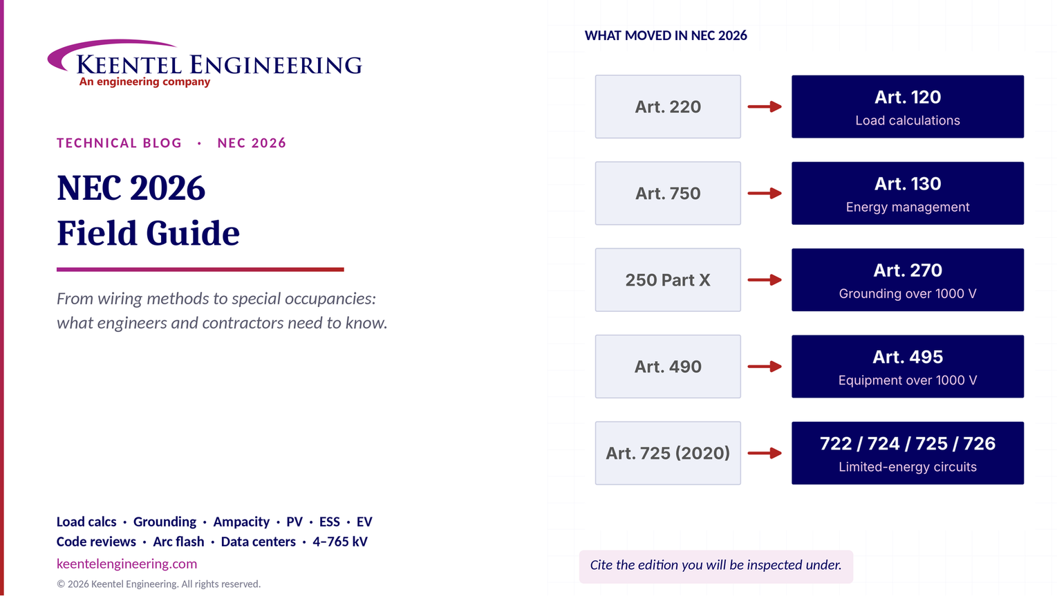
| Branch-circuit, feeder and service load calculations moved into Chapter 1 | Article 220 | New Article 120 | Every load calculation on a permit set now cites Article 120 sections; Article 220 references on drawings are out of date under 2026 |
| Energy management systems moved into Chapter 1 | Article 750 | New Article 130 | Load management and power control are now treated as general tools that affect load calculations across the Code |
| Grounding and bonding of systems over 1000 V ac / 1500 V dc consolidated | Article 250 Part X and scattered sections | Article 270 | Medium-voltage grounding rules are in one place |
| Equipment over 1000 V ac / 1500 V dc consolidated | Article 490 and others | Article 495 | Switchgear, substations and MV equipment requirements gathered in one article |
| Continued separation of over-1000 V branch circuits, feeders, services, OCPD and wiring methods | Begun in 2023 (Articles 235, 245, 305, 311, 315) | Expanded and refined | Low-voltage articles read more simply; MV designers must use the MV articles |
| Power control systems recognized in load calculations | 705.13 and scattered | Expanded across Article 120 and Chapter 7 | A listed power control system can limit the calculated load or source current, avoiding unnecessary service upgrades |
| Limited-energy circuits reorganized (from 2023) | Article 725 (2020) | Articles 722, 724, 725, 726 | Class 1 circuits are in Article 724; Class 2 and 3 in Article 725; Class 4 fault-managed power in Article 726 |
Beyond the reorganization, the 2026 edition revised many technical requirements. These include ground-fault and arc-fault circuit-interrupter provisions, requirements for replacing damaged wiring, rules for 10 A branch circuits, dwelling-unit load calculation values, EV charging and bidirectional equipment, PV and ESS, and equipment over 1000 V. Because several of these values (for example the dwelling general lighting unit load) are new and still being absorbed by industry training material, we flag them where they appear and recommend confirming the value in the adopted edition.
How Keentel Engineering helps here. When a jurisdiction moves from 2020 or 2023 to 2026, Keentel prepares code-transition reviews for owners with multi-site programs: a section-by-section map of what changes in their standard details, specifications and load-calculation templates, so drawings submitted after the adoption date cite the correct sections and pass plan review the first time.
How the Code is organized
The NEC is organized in an introduction (Article 90), nine chapters and informative annexes. Section 90.3 explains how the chapters relate, and this structure is the key to using the Code quickly.

Figure 1. NEC organization and where typical Keentel project types land. Chapters 1–4 apply generally; Chapters 5, 6 and 7 apply to special occupancies, special equipment and special conditions and may supplement or modify Chapters 1–4. Chapter 8 covers communications systems and is not subject to Chapters 1–7 unless specifically referenced. Chapter 9 contains tables that are applicable as referenced.
The practical rule is simple. Start with the special article (for example Article 625 for EV charging or Article 706 for ESS), apply what it says, and then apply Chapters 1 through 4 for everything the special article does not modify. Engineers who start in Chapter 3 and never open the special article are the source of many plan-review comments.
Article 90 states that the purpose of the Code is the practical safeguarding of persons and property from hazards arising from the use of electricity. It is not a design specification and not an instruction manual for untrained persons. Compliance with the Code and proper maintenance result in an installation that is essentially free from hazard, but not necessarily efficient, convenient or adequate for future expansion. That distinction matters: a Code-minimum service is not the same as a well-designed service, and good engineering often exceeds the minimum.
Section 90.2 defines what is covered and what is not. The Code covers premises wiring in public and private buildings, structures, mobile homes, recreational vehicles, floating buildings, yards, carnivals, parking lots, industrial substations and installations of conductors and equipment that connect to the supply of electricity. It does not cover installations under the exclusive control of an electric utility for the purpose of generation, transmission, distribution or metering, nor installations of railways for generation, transformation, transmission or distribution of power used exclusively for railway operation, nor ships, aircraft and automotive vehicles other than mobile homes and recreational vehicles. Utility facilities are governed by the National Electrical Safety Code (NESC, IEEE C2). Where a utility-scale solar or BESS plant is owned by an independent power producer rather than a utility, the boundary between NEC and NESC is a frequent design question; Article 691 and the AHJ's interpretation govern.
Section 90.4 makes the authority having jurisdiction (AHJ) responsible for interpreting the rules, approving equipment and materials, and granting special permission. The AHJ can be a building official, a fire marshal, an electrical inspector, an insurance representative or another office, depending on the jurisdiction. The NEC is revised on a three-year cycle, and states and cities adopt editions on their own schedules, often with amendments.
How Keentel Engineering helps here. For utility-scale PV, BESS and substation projects, Keentel documents the NEC/NESC boundary on the one-line diagram and in the basis of design: which equipment is premises wiring under the NEC, which is utility-type supply equipment under the NESC, and which listing and inspection path applies. Settling this early avoids late surprises with the AHJ and the utility.
Common misconceptions we correct in plan review
The following table lists misconceptions we regularly see in permit drawings, specifications, exam-preparation material and field practice. Several appear in widely circulated study aids. Each is explained in the section indicated.
| Common statement | Correct position | Where |
|---|---|---|
| "Service conductors may not be spliced between the point of attachment and the service disconnect." | Splices and taps in service conductors are permitted where made according to 110.14, 300.5(E), 300.13 and 300.15 (230.46). Connectors must be listed and, under recent editions, marked as suitable for use on the line side of service equipment. | Section 5 |
| "Service-drop clearance over a roof with a slope of 4 in 12 or more is 18 inches." | The general clearance above a roof is 8 ft 6 in. For 300 V or less and a slope of at least 4 in 12, it may be reduced to 3 ft. The 18 in reduction applies only to the overhanging portion of the roof near a through-the-roof mast, within the limits of 230.24(A). | Section 5 |
| "You may always have up to six service disconnects in one enclosure." | Since 2020, two to six disconnects are permitted only where each is in a separate enclosure, or grouped in switchgear, switchboards or metering centers with barriers or compartments as 230.71(B) requires. | Section 5 |
| "Type NM cable is limited to buildings of three floors." | The three-floor limit was removed many editions ago. Type NM use is now based on building construction type and occupancy (334.10 and 334.12), not floor count. | Section 7 |
| "LFMC is limited to 6 ft by 350.30(A)." | 350.30 covers securing and supporting. The 6 ft limit applies when LFMC is used as the equipment grounding conductor (250.118). Otherwise there is no general length limit. | Section 7 |
| "Dedicated electrical space above switchboards and panelboards extends 25 ft." | The dedicated space extends from the floor to 6 ft above the equipment or to the structural ceiling, whichever is lower (110.26(E)(1)). | Section 3 |
| "A 120 V room air conditioner cord is limited to 6 ft." | The cord length limit is 10 ft for 120 V units and 6 ft for 208 V or 240 V units (440.64). | Section 9 |
| "Transformer primary protection at 125% protects the transformer and its secondary." | 450.3(B) protects the transformer. Secondary conductors still need protection under 240.21(C); primary-only protection protects secondary conductors only in the limited cases 240.21(C)(1) allows. | Section 9 |
| "Article 725 covers Class 1, 2 and 3 circuits." | Since 2023, general requirements are in Article 722, Class 1 in Article 724, Class 2 and Class 3 in Article 725, and Class 4 fault-managed power in Article 726. | Section 12 |
| "Article 552 covers park trailers." | Park trailer requirements were relocated into Article 551 in the 2023 edition. | Section 10 |
| "Hallway receptacles are covered by 210.52(G)." | 210.52(G) covers basements, garages and accessory buildings; hallways are 210.52(H). | Section 4 |
| "Load calculations are in Article 220." | Under NEC 2026, branch-circuit, feeder and service load calculations are in Article 120. Article 220 references remain valid only where the 2023 or earlier edition is enforced. | Section 4 |
| "Section 110.16 requires shock and arc-flash warnings." | 110.16 requires arc-flash hazard warning marking, and for larger service and feeder equipment additional information such as voltage and available fault current. Shock-hazard boundary information on the label comes from NFPA 70E practice. | Section 3 |
| "The system bonding jumper for a separately derived system goes at both the source and the first disconnect." | It is installed at one point only: at the source or at the first system disconnecting means, never both (250.30(A)(1)), to avoid parallel neutral current paths. | Section 6 |
| "OCPDs may not be located in bathrooms" (as the only answer). | Dwelling and guest-room OCPDs are prohibited both in bathrooms (240.24(E)) and in clothes closets (240.24(D)), and must not be over the steps of a stairway. | Section 5 |
| "GFCI receptacles must be tested monthly under the NEC." | The NEC does not set a test interval for installed GFCIs. Manufacturers' instructions, NFPA 70B maintenance programs and owner policy do. | Section 4 |
How Keentel Engineering helps here. Keentel's code-compliance review checks permit drawings and specifications against the adopted edition before submittal. We look specifically for out-of-date section references, misapplied exceptions and the misconceptions above, which are the most common causes of correction notices and change orders.
Eight findings for decision makers
- Cite the edition you are being inspected under. Many AHJs are still on 2020 or 2023. A 2026 drawing set submitted to a 2023 jurisdiction (or the reverse) invites comments. Section numbers changed in load calculations, EMS, medium voltage and limited-energy circuits.
- Load calculations now live in Article 120, and power control systems can reduce them. For EV charging, PV-plus-storage and electrification retrofits, a listed power control system or energy management system can avoid a service upgrade.
- Medium voltage has its own articles. Data center campuses, BESS and solar collector systems at 4.16, 13.8 and 34.5 kV must be designed to Articles 235, 245, 270, 305, 311, 315 and 495, not to the low-voltage rules.
- Ampacity is a chain, not a table lookup. Ambient correction, bundling adjustment, terminal temperature limits and continuous-load factors interact. Most field failures of conductor sizing come from skipping one link.
- Grounding and bonding are still the most misunderstood part of the Code. Separately derived systems, supply-side bonding and multiple sources (PV, ESS, generators) need a deliberate design.
- Special articles modify general rules. For EV charging, PV, ESS, fire pumps, emergency systems and data rooms, start with the special article.
- Life-safety systems are held to a higher standard. Emergency (700), legally required standby (701), critical operations power (708) and fire pumps (695) require selective coordination, separation and testing that go well beyond ordinary feeders.
- The Code is the minimum. Reliability, maintainability, arc-flash energy and future expansion require engineering judgment above the minimum, especially in data centers and critical facilities.
Key terms
| Term | Meaning in plain language |
|---|---|
| AHJ | Authority having jurisdiction: the person or office that enforces and interprets the Code locally |
| Branch circuit | Conductors between the final overcurrent device and the outlets |
| Feeder | Conductors between the service equipment, a separately derived system or other source and the final branch-circuit overcurrent device |
| Service | Conductors and equipment that deliver energy from the serving utility to the premises wiring |
| Continuous load | A load whose maximum current is expected to continue for 3 hours or more |
| Ground fault | An unintentional connection between an ungrounded conductor and normally non-current-carrying metal parts, enclosures, raceways or earth |
| Equipment grounding conductor (EGC) | The conductive path that connects non-current-carrying metal parts to the system grounded conductor and electrode |
| Grounding electrode conductor (GEC) | The conductor that connects the system or equipment to the grounding electrode system |
| Separately derived system | A source, such as a transformer or generator, with no direct connection to the supply conductors of another system except through grounding and bonding |
| Listed | Included on a list published by a recognized testing organization, such as a nationally recognized testing laboratory |
| Accessible (equipment) | Capable of being reached for operation, renewal or inspection, not guarded by locked doors, elevation or other effective means |
| Readily accessible | Capable of being reached quickly without climbing over obstacles, using portable ladders or requiring tools |
| Power control system (PCS) | A listed system that limits current or power from sources and storage to a set value, used to protect conductors and busbars |
Part B — The Code in Depth, Chapter by Chapter
1. Article 100: definitions that drive design decisions
Article 100 is where many disputes with inspectors begin and end. The Code uses defined terms precisely, and the difference between two similar words often decides whether an installation passes.
Accessible and readily accessible. Equipment that is accessible can be reached for operation, renewal or inspection; it is not guarded by locked doors, elevation or other effective means. Readily accessible adds speed and convenience: no climbing over obstacles, no portable ladders and no tools. Service disconnects, many emergency disconnects and the disconnects for certain equipment must be readily accessible. A disconnect above a suspended ceiling is accessible at best, and a disconnect in a locked room is readily accessible only to those with the key, which the Code addresses separately for specific equipment.
Branch circuit and feeder. A branch circuit is the conductors between the final overcurrent device protecting the circuit and the outlets. A feeder is all circuit conductors between the service equipment, the source of a separately derived system or another power supply source, and the final branch-circuit overcurrent device. The distinction controls which sizing rules apply: Article 210 for branch circuits, Article 215 for feeders and Article 120 (formerly 220) for both calculations.
Dwelling unit. A single unit providing complete and independent living facilities for one or more persons, with permanent provisions for living, sleeping, cooking and sanitation. A hotel room with a kitchenette may or may not meet the definition, which changes GFCI, AFCI, receptacle spacing and load calculation rules. Designers of extended-stay hotels and senior living facilities should confirm the classification with the AHJ.
Ground fault and grounded. A ground fault is an unintentional, electrically conducting connection between an ungrounded conductor and normally non-current-carrying conductors, metal enclosures, metal raceways, metal equipment or the earth. It is not "any current that flows in the earth." The definition matters in understanding why the effective ground-fault current path in 250.4 must be a low-impedance metallic path: the earth is not an effective fault-current path.
Authority having jurisdiction. An organization, office or individual responsible for enforcing a code or standard, or for approving equipment, materials, an installation or a procedure. The AHJ may be the electrical inspector, the fire marshal, the building official or, for some facilities, an insurer or the owner's own designated official.
How Keentel Engineering helps here. Keentel's design basis memoranda define occupancy, system types and boundaries in Code terms at the start of a project: which conductors are service versus feeder, which systems are separately derived, which spaces are dwelling units or patient care spaces. Getting the definitions right on day one prevents redesign after plan review.
2. Article 200: identifying the grounded conductor
The grounded conductor (usually the neutral) must be identifiable throughout the system. For conductors 6 AWG and smaller, identification is by a continuous white or gray outer finish, or by three continuous white or gray stripes on other than green insulation (200.6(A)). Conductors 4 AWG and larger may be identified at terminations by a distinctive white or gray marking applied at the time of installation (200.6(B)). Where grounded conductors of different systems share an enclosure, each system's grounded conductor must be distinguishable, for example white for the 208Y/120 V system and gray for the 480Y/277 V system, with the method documented at the panelboard or posted at the premises (200.6(D)).
Terminals intended for connection of the grounded conductor are identified by a metallic coating substantially white in color (commonly a silver or nickel-plated screw), or by the word "white" or the letter "W" adjacent to the terminal (200.10). Polarity matters: reversing the grounded and ungrounded conductors on a receptacle or lampholder energizes the screw shell or the wrong blade and creates a shock hazard even though the circuit appears to work.
In buildings with both 208Y/120 V and 480Y/277 V systems, which is common in commercial buildings and almost universal in data centers, inconsistent neutral identification is one of the most frequent field findings. The convention should be specified in Division 26 specifications and verified at rough-in.
How Keentel Engineering helps here. Keentel's specifications set a single conductor identification standard for each project (phase colors, neutral colors by system, EGC identification and labeling) and include it on the one-line diagram legend, so the field crews, the inspector and the facility's future maintenance staff all read the same convention.
3. Article 110: requirements for electrical installations
Section 110.3(B) requires listed or labeled equipment to be installed and used in accordance with any instructions included in the listing or labeling. This short sentence is the hook by which manufacturers' installation instructions become enforceable Code requirements: torque values, conductor temperature ratings, breaker types allowed in a panelboard, clearances for inverters and ESS, and series-rating combinations. Section 110.3(C) requires that product evaluations for listing be performed by qualified testing laboratories recognized by the AHJ.
Section 110.14(D) requires terminal tightening torque to follow the manufacturer's value, using a calibrated torque tool or another method approved by the manufacturer. Loose terminations are a leading cause of thermal failures found by infrared surveys, and they are now squarely within the NFPA 70B maintenance scope as well.
Unused openings other than those intended for the operation of equipment, mounting or drainage must be closed to afford protection substantially equivalent to the wall of the equipment (110.12(A)). Tape, caulk and cardboard are not acceptable. Metal plugs or plates used with nonmetallic enclosures must be recessed at least 1/4 in from the outer surface.
Section 110.16 requires electrical equipment such as switchboards, switchgear, panelboards, industrial control panels, meter socket enclosures and motor control centers that are likely to require examination, adjustment, servicing or maintenance while energized to be field or factory marked to warn qualified persons of potential arc-flash hazards. For service equipment and feeder supplied equipment of larger ratings, the marking must also include specific information such as the nominal system voltage, the available fault current at the line terminals, the clearing time of the service OCPD and the date of the calculation, or alternatively the arc-flash label information required by NFPA 70E. The detailed incident energy and arc-flash boundary on a label come from an arc-flash study performed under NFPA 70E using IEEE 1584 methods.
Section 110.9 requires equipment intended to interrupt current at fault levels to have an interrupting rating sufficient for the nominal circuit voltage and the current available at the line terminals. Section 110.10 requires the overcurrent devices, the total impedance, the equipment short-circuit current ratings and other characteristics of the circuit to be selected and coordinated so that the protective devices clear a fault without extensive damage. Section 110.24 requires service equipment in other than dwelling units to be marked with the maximum available fault current and the date of the calculation, and the marking must be updated when modifications change the available fault current.
Working space in front of equipment that may require examination, adjustment, servicing or maintenance while energized is defined in 110.26(A). The required depth depends on the nominal voltage to ground and the condition behind the worker.
| Nominal voltage to ground | Condition 1 | Condition 2 | Condition 3 |
|---|---|---|---|
| 0–150 V | 3 ft | 3 ft | 3 ft |
| 151–600 V | 3 ft | 3 1/2 ft | 4 ft |
| 601–1000 V | 3 ft | 4 ft | 5 ft |
Condition 1 has exposed live parts on one side and no live or grounded parts on the other (or both sides effectively guarded). Condition 2 has exposed live parts on one side and grounded parts, such as concrete or masonry, on the other. Condition 3 has exposed live parts on both sides. A 480Y/277 V switchboard facing a concrete wall is Condition 2 and needs 3 1/2 ft; the same switchboard facing another energized lineup is Condition 3 and needs 4 ft.
The working space must be at least 30 in wide or the width of the equipment, whichever is greater, and equipment doors must be able to open at least 90 degrees. The height of the working space is 6 1/2 ft or the height of the equipment, whichever is greater (110.26(A)(3)); some exceptions apply to dwelling service equipment and small panelboards. Working space may not be used for storage.
Entrances. For equipment rated 1200 A or more that contains overcurrent devices, switching devices or control devices and is over 6 ft wide, there must be one entrance to and egress from the working space at least 24 in wide and 6 1/2 ft high at each end of the working space (110.26(C)(2)). A single entrance is permitted where the location permits a continuous and unobstructed way of egress travel, or where the working space depth is doubled. Where personnel doors are within 25 ft of the nearest edge of the working space for such equipment, the doors must open in the direction of egress and be equipped with listed panic or fire exit hardware (110.26(C)(3)).
Dedicated equipment space. Indoor switchboards, switchgear, panelboards and motor control centers must have a dedicated electrical space equal to the width and depth of the equipment, extending from the floor to a height of 6 ft above the equipment or to the structural ceiling, whichever is lower (110.26(E)(1)). Piping, ducts, leak protection apparatus and equipment foreign to the electrical installation may not be located in this zone. A sprinkler head is permitted; a water pipe passing over the switchboard is not.
Illumination. Working spaces about service equipment, switchboards, switchgear, panelboards and motor control centers installed indoors must be illuminated, and the lighting may not be controlled solely by automatic means (110.26(D)).
Over 1000 V, Part III of Article 110 and the medium-voltage articles set larger working spaces, entrance requirements and guarding rules.
How Keentel Engineering helps here. Keentel's electrical room layouts are drawn to scale with working space, door swing, dedicated space and egress shown on the plan, checked against the equipment submittals rather than catalog dimensions. In data centers and BESS enclosures, where space is expensive, this avoids discovering at installation that a 2,000 A switchboard needs a second exit.
4. Branch circuits and load calculations (Articles 210, 215 and 120)
Branch circuits are rated by the maximum ampere rating or setting of the overcurrent device. Standard ratings for circuits supplying multiple outlets are 10 A (added in 2023 for limited uses), 15, 20, 30, 40 and 50 A in most occupancies. A 20 A branch circuit supplying two or more receptacles may use 15 A or 20 A receptacles (Table 210.21(B)(3)). A single receptacle on an individual branch circuit must have a rating not less than the branch circuit, so a single 15 A receptacle on a 20 A individual circuit is not permitted; a duplex receptacle counts as two receptacles.
Section 210.20(A) requires the branch-circuit overcurrent device to be rated not less than the noncontinuous load plus 125% of the continuous load, unless the assembly including the overcurrent device is listed for operation at 100% of its rating. Stated the other way round, continuous load on a standard breaker should not exceed 80% of its rating.
Section 210.8 has expanded in nearly every edition. For dwelling units, GFCI protection is required for 125 V through 250 V receptacles supplied by single-phase branch circuits rated 150 V or less to ground in bathrooms, garages and accessory buildings, outdoors, crawl spaces, basements, kitchens (all receptacles in the kitchen, not only countertop receptacles), areas with sinks within 6 ft of the bowl edge, boathouses, bathtub and shower areas, laundry areas and indoor damp and wet locations. Section 210.8(B) extends similar protection in other than dwelling units, and 210.8(D) and (F) cover specific appliances and outdoor outlets. The 2026 edition refined several of these provisions; designers should confirm the list against the adopted edition and note where listed special-purpose GFCI devices are permitted for higher-voltage equipment.
The NEC does not prescribe how often a GFCI must be tested after installation. Manufacturers' instructions typically call for monthly testing, and a facility's NFPA 70B electrical maintenance program should set an interval and document it.
Section 210.12 requires arc-fault circuit-interrupter protection for 120 V, 15 A and 20 A branch circuits supplying outlets or devices in dwelling-unit kitchens, family rooms, dining rooms, living rooms, parlors, libraries, dens, bedrooms, sunrooms, recreation rooms, closets, hallways, laundry areas and similar rooms or areas. Similar requirements apply to dormitory units and to guest rooms and guest suites of hotels and motels. Extensions and modifications to existing circuits trigger AFCI requirements, with exceptions for short extensions.
| Location | Requirement (paraphrased) | Section |
|---|---|---|
| Habitable rooms (wall space) | No point along the floor line of any wall space more than 6 ft from a receptacle | 210.52(A) |
| Kitchen countertops | No point along the wall line more than 24 in from a receptacle; receptacles for each countertop space 12 in or wider | 210.52(C) |
| Bathrooms | At least one receptacle within 3 ft of the outside edge of each basin | 210.52(D) |
| Outdoors | At least one at the front and one at the back of a one-family dwelling, readily accessible from grade | 210.52(E) |
| Laundry | At least one receptacle for the laundry | 210.52(F) |
| Basements, garages, accessory buildings | Receptacle required in each separate unfinished portion and each vehicle bay | 210.52(G) |
| Hallways | At least one receptacle in hallways 10 ft or more in length | 210.52(H) |
The rules for kitchen islands and peninsulas changed in 2023: receptacles are no longer required on islands and peninsulas, but where they are installed they must meet location rules, and provisions for future receptacles may be required. Check the adopted edition.
Dwelling kitchens require at least two 20 A small-appliance branch circuits for the countertop and dining receptacles (210.11(C)(1)), plus at least one 20 A laundry circuit and at least one 20 A bathroom circuit.
Feeder conductors must have an ampacity not less than the noncontinuous load plus 125% of the continuous load (215.2(A)(1)), before any adjustment or correction factors, and not less than the calculated load after adjustment and correction. The feeder neutral is sized to carry the maximum unbalanced load (Article 120, formerly 220.61), which may be reduced for certain loads but must never be reduced for nonlinear loads where harmonic currents add in the neutral.
Under the 2026 edition, the methods formerly in Article 220 are in Article 120. The structure is familiar: general requirements, branch-circuit load calculations, feeder and service calculations (the standard method), optional calculations for dwellings and other occupancies, and calculations for farm loads. Key values used in a standard dwelling calculation include:
| Item | Value (paraphrased) | Notes |
|---|---|---|
| General lighting, dwelling | Unit load per square foot from the general lighting table | 3 VA/ft² under the 2023 edition; the 2026 edition revisited the dwelling unit load, so confirm the value in the adopted table |
| Small-appliance circuits | 1500 VA per circuit | At least two circuits |
| Laundry circuit | 1500 VA | |
| Lighting demand factors, dwellings | First 3000 VA at 100%, 3001–120,000 VA at 35%, remainder at 25% | Applies to general lighting plus small-appliance and laundry loads |
| Fastened-in-place appliances | 75% when four or more | Excludes ranges, dryers, space heating and A/C |
| Household dryer | 5000 W or nameplate, whichever is larger | |
| Ranges | Demand from the range table | 8 kW for one range of 12 kW or less |
| Heating and A/C | Larger of the two (noncoincident loads) | |
| EV supply equipment | 7200 W or nameplate, whichever is larger | Formerly 220.57 |
| Range and dryer neutral | 70% of the demand load | Formerly 220.61(B) |
A 2,400 ft² one-family dwelling has two small-appliance circuits, one laundry circuit, a 12 kW range, a 5 kW dryer, a 4.5 kW water heater, a 1.2 kW dishwasher, a 0.9 kW disposal, a 1.5 kW built-in microwave, 10 kW of electric heat, a 5 kVA heat pump condensing unit (noncoincident with the heat strips for this example) and a 32 A, 240 V Level 2 EV charger. The supply is 120/240 V single phase. We use 3 VA/ft² for the general lighting load to show the method; substitute the value in the adopted edition.
| Step | Load | Calculation | Demand (VA) |
|---|---|---|---|
| 1 | General lighting | 2,400 ft² × 3 VA/ft² | 7,200 |
| 2 | Small appliance and laundry | 3 × 1,500 VA | 4,500 |
| 3 | Subtotal | 7,200 + 4,500 = 11,700 | |
| 4 | Lighting demand | 3,000 × 100% + 8,700 × 35% | 6,045 |
| 5 | Range | One range, 12 kW or less | 8,000 |
| 6 | Dryer | Nameplate 5,000 W (not less than 5,000 W) | 5,000 |
| 7 | Fastened appliances | (4,500 + 1,200 + 900 + 1,500) × 75% | 6,075 |
| 8 | Heat versus A/C | Larger: heat 10,000 W | 10,000 |
| 9 | EV charger | Larger of 7,200 W or 32 A × 240 V = 7,680 W | 7,680 |
| 10 | Total | 42,800 |

The calculated load is 178 A, so a 200 A service is the minimum standard size. The Code's absolute minimum for a one-family dwelling service is 100 A (230.79(C)), but the calculation governs. Note how much the EV charger drives the answer: without it, the load would be about 147 A. Under the 2026 edition, an energy management system complying with Article 130 can limit the EV load included in the calculation, often avoiding a service upgrade in existing homes.
A feeder supplies 120 A of continuous lighting and receptacle load and 40 A of noncontinuous load. The equipment terminals are rated 75 °C.

From the 75 °C column of Table 310.16, 3/0 AWG copper is rated 200 A, so it is the minimum conductor before any correction or adjustment. A 200 A standard breaker (not 100% rated) is appropriate. If the feeder ran through a hot rooftop or shared a raceway with other circuits, the derated ampacity must also be checked, as Worked example 6 shows.
How Keentel Engineering helps here. Keentel prepares load calculations under the adopted edition (Article 220 or Article 120) for dwellings, multifamily, commercial, EV charging depots and data centers, and documents them in the format plan reviewers expect. For existing buildings adding EV chargers or heat pumps, we use measured demand (formerly 220.87, now in Article 120) and listed energy management systems to avoid unnecessary service upgrades.
5. Services, feeders and overcurrent protection (Articles 225, 230, 240 and 408)
Service conductors are permitted to be spliced or tapped in accordance with 110.14, 300.5(E), 300.13 and 300.15 (230.46). Recent editions added a requirement that pressure connectors and devices for splices and taps installed on service conductors be marked "suitable for use on the line side of the service equipment" or equivalent. The rule is not that service conductors may never be spliced; the rule is that splices must use the right listed hardware in an accessible enclosure where required.
| Situation | Minimum clearance (paraphrased) | Section |
|---|---|---|
| Above roofs, general | 8 ft 6 in vertically | 230.24(A) |
| Above roofs, 300 V or less, slope at least 4 in 12 | May be reduced to 3 ft | 230.24(A) Exception |
| Overhang portion near a through-the-roof mast, 300 V or less | 18 in, limited to not more than 6 ft of conductors passing over not more than 4 ft of overhang, terminating at a through-the-roof raceway or approved support | 230.24(A) Exception |
| Above finished grade, sidewalks, platforms accessible to pedestrians only, 150 V to ground or less | 10 ft | 230.24(B) |
| Residential property and driveways, commercial areas not subject to truck traffic, 300 V or less | 12 ft | 230.24(B) |
| Same, exceeding 300 V to ground | 15 ft | 230.24(B) |
| Public streets, alleys, roads, parking areas subject to truck traffic, driveways on other than residential property | 18 ft | 230.24(B) |
The service disconnecting means must be installed at a readily accessible location either outside the building or inside nearest the point of entrance of the service conductors (230.70(A)). The AHJ often sets a maximum length of service conductors inside the building. For one- and two-family dwellings, an emergency disconnect must be installed at a readily accessible outdoor location (230.85), so first responders can de-energize the building without entering it.
Each service may have one disconnect, or two to six disconnects where each is in a separate enclosure, or grouped in switchgear, switchboards, metering centers or panelboards with the barriers and compartments 230.71(B) requires. The older practice of six main breakers in a single panelboard without separation is no longer permitted.
Ground-fault protection of equipment is required for solidly grounded wye services of more than 150 V to ground but not more than 1000 V phase to phase, for each service disconnect rated 1000 A or more (230.95). This rule captures most 480Y/277 V services at commercial buildings and data centers. The maximum setting is 1200 A, and the maximum time delay is one second for ground-fault currents of 3000 A or more. Section 215.10 and 240.13 apply similar requirements to feeders and building disconnects. Performance testing of the GFP system is required when first installed (230.95(C)).
Conductors must be protected against overcurrent in accordance with their ampacities (240.4). Three rules are worth memorizing:
- Next size up (240.4(B)). Where the ampacity of a conductor does not match a standard OCPD rating, the next higher standard rating is permitted if the conductors are not part of a branch circuit supplying more than one receptacle for cord-and-plug-connected portable loads, the ampacity does not correspond to a standard rating, and the next higher standard rating does not exceed 800 A.
- Small conductors (240.4(D)). Unless specifically permitted, 14 AWG copper is limited to 15 A, 12 AWG copper to 20 A and 10 AWG copper to 30 A; 12 AWG aluminum to 15 A and 10 AWG aluminum to 25 A.
- Standard ratings (240.6(A)). Standard ratings include 15, 20, 25, 30, 35, 40, 45, 50, 60, 70, 80, 90, 100, 110, 125, 150, 175, 200, 225, 250, 300 and higher values. 1, 3, 6 and 10 A are additional standard ratings for fuses, and 10 A is now a standard breaker rating. 55 A is not a standard rating.
The OCPD must be located at the point where the conductors receive their supply (240.21), with the tap and transformer secondary exceptions of 240.21(B) and (C). In dwelling units and guest rooms, OCPDs may not be located in bathrooms (240.24(E)), in clothes closets or near easily ignitible material (240.24(D)), or over the steps of a stairway (240.24(F)). Fuseholders must not be altered to accept fuses of a higher rating than the design rating, and Type S fuses and adapters are designed to be non-tamperable for that reason.
Arc energy reduction (240.87). Where the highest continuous current trip setting of a circuit breaker, or the rating of the largest breaker that can be installed, is 1200 A or higher, a method to reduce clearing time must be provided. Accepted methods include zone-selective interlocking, differential relaying, an energy-reducing maintenance switch with local status indicator, an energy-reducing active arc-flash mitigation system, an instantaneous trip setting below the available arcing current, an instantaneous override below the arcing current, or an approved equivalent. Section 240.67 imposes a similar requirement on fuses rated 1200 A and above. Documentation showing the method reduces clearing time is required, and performance testing of the method is required when first installed.
Every circuit and circuit modification must be legibly identified as to its clear, evident and specific purpose on a circuit directory located on the face of, inside or adjacent to the panel door (408.4(A)). Spare positions with unused overcurrent devices must be described accordingly. Each panelboard must be protected by an overcurrent device with a rating not greater than that of the panelboard, located within or on the supply side of the panelboard (408.36).
How Keentel Engineering helps here. For data centers and large commercial services, Keentel's one-line diagrams and coordination studies show the 230.95 ground-fault protection settings, the 240.87 arc energy reduction method for every 1200 A and larger breaker, and the series-rated and fully rated combinations, so that the inspector's performance-testing witness and the owner's arc-flash labels are based on the same settings.
6. Grounding and bonding (Articles 250 and 270)
Section 250.4 explains why we ground and bond. Electrical systems that are grounded are connected to earth to limit the voltage imposed by lightning, line surges or unintentional contact with higher-voltage lines, and to stabilize the voltage to earth during normal operation. Equipment is bonded together and to the system grounded conductor to create an effective ground-fault current path: a permanent, low-impedance path capable of safely carrying the maximum ground-fault current so that the overcurrent device operates quickly. The earth is not considered an effective ground-fault current path.
All electrodes present at a building must be bonded together to form the grounding electrode system (250.50). Permitted electrodes include metal underground water pipe in contact with earth for 10 ft or more (which must be supplemented), the metal frame of the building where effectively grounded, concrete-encased electrodes, ground rings, rod and pipe electrodes, plate electrodes and other listed electrodes (250.52). Metal underground gas piping, aluminum and plastic water pipe may not be used as electrodes.
A concrete-encased electrode consists of at least 20 ft of one or more bare or zinc-galvanized steel reinforcing bars not smaller than 1/2 in diameter, or at least 20 ft of bare copper conductor not smaller than 4 AWG, encased by at least 2 in of concrete and in direct contact with the earth (250.52(A)(3)). Where present in a new building's footing, it must be used.
Rod electrodes must be installed so that at least 8 ft of length is in contact with the soil (250.53(A)(4)). A single rod, pipe or plate electrode must be supplemented by an additional electrode unless the single electrode has a resistance to earth of 25 ohms or less (250.53(A)(2)). Supplemental electrodes must be at least 6 ft apart. In practice, most installers simply install two rods rather than test.
The grounding electrode conductor is sized from Table 250.66 based on the size of the largest ungrounded service-entrance conductor or equivalent area of parallel conductors.
| Largest service conductor (copper) | Copper GEC |
|---|---|
| 2 AWG or smaller | 8 AWG |
| 1 or 1/0 AWG | 6 AWG |
| 2/0 or 3/0 AWG | 4 AWG |
| Over 3/0 through 350 kcmil | 2 AWG |
| Over 350 through 600 kcmil | 1/0 AWG |
| Over 600 through 1100 kcmil | 2/0 AWG |
| Over 1100 kcmil | 3/0 AWG |
The GEC to a rod, pipe or plate electrode need not be larger than 6 AWG copper; to a concrete-encased electrode, not larger than 4 AWG copper; to a ground ring, not larger than the ring conductor (250.66(A)–(C)). The GEC must be installed in one continuous length, or spliced only by irreversible compression connectors listed as grounding and bonding equipment or by the exothermic welding process (250.64(C)).
The equipment grounding conductor is sized from Table 250.122 based on the rating of the overcurrent device ahead of the circuit.
| OCPD rating (A) | Copper EGC | Aluminum EGC |
|---|---|---|
| 15 | 14 AWG | 12 AWG |
| 20 | 12 AWG | 10 AWG |
| 60 | 10 AWG | 8 AWG |
| 100 | 8 AWG | 6 AWG |
| 200 | 6 AWG | 4 AWG |
| 400 | 3 AWG | 1 AWG |
| 800 | 1/0 AWG | 3/0 AWG |
| 1200 | 3/0 AWG | 250 kcmil |
Where ungrounded conductors are increased in size for voltage drop, the EGC must be increased proportionally by circular-mil area (250.122(B)). Where conductors are run in parallel in separate raceways, a full-size EGC is required in each raceway (250.122(F)).
A 1,200 A, 480Y/277 V service uses three parallel sets of 500 kcmil copper per phase (1,500 kcmil equivalent). A 400 A feeder from the switchboard supplies a mechanical panel.
- GEC: the equivalent area exceeds 1,100 kcmil, so the GEC to the building steel or water pipe is 3/0 AWG copper. If the only electrode were a rod, 6 AWG copper would suffice for that electrode connection.
- Feeder EGC: the 400 A OCPD requires 3 AWG copper from Table 250.122. If the feeder conductors were upsized from 600 kcmil to 750 kcmil for voltage drop, the EGC must be increased by the ratio 750/600 = 1.25, from 3 AWG (52,620 cmil) to at least 65,775 cmil, which is 2 AWG (66,360 cmil).
- Service GFP: each service disconnect of 1,000 A or more requires ground-fault protection of equipment (230.95), and the 1,200 A main also requires arc energy reduction (240.87).
The main bonding jumper connects the grounded conductor and the equipment grounding conductor at the service (250.24(B), 250.28). It is the single point at which neutral and ground are joined for the service; downstream of the service, the neutral and the EGC must remain separate. The system bonding jumper performs the same function for a separately derived system (250.30(A)(1)) and is installed at a single location: at the source or at the first system disconnecting means, but not at both. Installing it at both creates parallel paths for neutral current on the EGC, raceways and building steel, which causes stray current, magnetic fields and nuisance tripping of ground-fault protection. The supply-side bonding jumper connects metal parts on the supply side of the service or of a separately derived system; it is sized from Table 250.102(C)(1).
A transformer with no direct electrical connection between primary and secondary, such as a 480 V delta to 208Y/120 V wye dry-type transformer, is a separately derived system. Its secondary needs a system bonding jumper, a grounding electrode conductor to an electrode (preferably building steel or the common grounding electrode conductor) and supply-side bonding. Generators, PV inverters and ESS can be separately derived or not, depending on whether the transfer switch or interconnection switches the neutral. A 3-pole transfer switch with a solidly connected neutral means the generator is not separately derived and must not have its own neutral-to-ground bond; a 4-pole switch makes it separately derived. This single decision drives ground-fault protection behavior, and mistakes are common in emergency and standby systems.
The 2026 edition consolidates grounding and bonding of systems over 1000 V ac and 1500 V dc into Article 270. Medium-voltage systems may be solidly grounded, low-impedance grounded or high-resistance grounded, and impedance-grounded neutral systems have specific requirements for the grounding impedance, its monitoring and labeling. Collector systems at solar and BESS plants (typically 34.5 kV), data center campus distribution (13.8 kV or 34.5 kV) and industrial MV systems should be designed with Article 270, IEEE Std 142, IEEE Std 80 for substations and the NESC where utility-type equipment is involved.
How Keentel Engineering helps here. Grounding is one of Keentel's core disciplines, from residential services to 765 kV substations. We design grounding electrode systems and ground grids to IEEE Std 80, specify bonding for separately derived systems, generators, PV and ESS, perform fall-of-potential and soil resistivity testing, and review neutral switching and GFP behavior in multi-source systems before the first transfer test.
7. Wiring methods (Chapter 3)
Article 300 applies to all wiring methods unless modified elsewhere. Its most important rules are:
- Conductors of the same circuit together (300.3(B)). All conductors of a circuit, including the grounded conductor and the EGC, must be in the same raceway, cable, trench or cord. Separating them causes inductive heating of metal raceways and enclosures and raises the impedance of the fault-return path.
- Different systems (300.3(C)). Conductors of ac and dc circuits rated 1000 V or less may occupy the same raceway, cable or enclosure only where all conductors have an insulation rating equal to at least the maximum circuit voltage applied to any conductor in the enclosure. Conductors over 1000 V may not share with conductors of 1000 V or less except as specifically permitted.
- Protection against physical damage (300.4). Where cables or raceway-type wiring methods pass through bored holes in wood framing, the edge of the hole must be at least 1 1/4 in from the nearest edge of the framing member, or the cable must be protected by a steel plate or bushing at least 1/16 in thick. Notches in wood members are treated the same way.
- Underground installations (300.5). Minimum cover depends on the wiring method and location, from Table 300.5. Typical values: direct-buried cables 24 in; rigid metal conduit and IMC 6 in; PVC and other nonmetallic raceways not encased in concrete 18 in; residential branch circuits rated 120 V or less with GFCI protection and an OCPD of 20 A or less 12 in. Under a driveway or in a street, deeper cover applies.
- Securing and supporting (300.11). Raceways and cables must be securely fastened in place. Ceiling support wires that are not part of the fire-rated design may not be used as the sole support, except where the ceiling system is identified for the purpose.
- Fire-resistive assemblies (300.21). Penetrations of fire-resistance-rated walls, partitions, floors and ceilings must be firestopped using approved methods that maintain the rating. Listed firestop systems with a specific design number are the usual approach.
- Ducts and plenums (300.22). Only specific wiring methods are permitted in ducts for dust, loose stock or vapor removal (none), in ducts for environmental air, and in other spaces used for environmental air (plenums). The rule matters for raised floors and ceiling plenums in data centers and offices.
- Enclosure of conductors. The general requirement that conductors be installed in a recognized wiring method appears throughout Chapter 3 and in 300.3(A), which requires single conductors to be installed only within a recognized wiring method.
Every box must have enough volume for the conductors, devices and fittings inside it. Box fill is calculated from Table 314.16(B), which assigns a volume allowance per conductor based on its size.
| Conductor size | Volume allowance per conductor |
|---|---|
| 18 AWG | 1.50 in³ |
| 16 AWG | 1.75 in³ |
| 14 AWG | 2.00 in³ |
| 12 AWG | 2.25 in³ |
| 10 AWG | 2.50 in³ |
| 8 AWG | 3.00 in³ |
| 6 AWG | 5.00 in³ |
The counting rules (314.16(B)) are where mistakes happen:
- Each conductor that originates outside the box and terminates or is spliced inside counts as one. A conductor that passes through without splice or termination counts as one; a looped, unbroken conductor 12 in or longer counts as two.
- All equipment grounding conductors together count as one allowance based on the largest EGC, with an additional 1/4 allowance for each EGC beyond four (a change made in recent editions).
- One or more internal cable clamps count as one allowance based on the largest conductor.
- Each yoke or strap containing one or more devices counts as two allowances based on the largest conductor connected to the device (a device wider than a single 2 in device box counts two for each gang required).
- Each luminaire stud or hickey counts as one.
- Small fittings such as locknuts and bushings are not counted.
All boxes must remain accessible after installation without removing any part of the building structure or finish (314.29). Boxes behind drywall or above a hard ceiling without an access panel are a violation.
A 4 in square by 2 1/8 in deep box (30.3 in³ from Table 314.16(A)) contains six 12 AWG insulated conductors, three 12 AWG equipment grounding conductors, one internal cable clamp and one duplex receptacle on 12 AWG conductors.
| Item | Count | Allowance | Volume |
|---|---|---|---|
| Insulated conductors | 6 | 2.25 in³ | 13.50 in³ |
| EGCs (up to four count as one) | 1 | 2.25 in³ | 2.25 in³ |
| Internal clamps | 1 | 2.25 in³ | 2.25 in³ |
| Device yoke | 2 | 2.25 in³ | 4.50 in³ |
| Total | 22.50 in³ |
The required 22.5 in³ is less than 30.3 in³, so the box is adequate. A 4 in square by 1 1/2 in box (21.0 in³) would not be.
| Wiring method | Article | Typical permitted uses | Key limits |
|---|---|---|---|
| Rigid metal conduit (RMC) | 344 | All atmospheric conditions and occupancies; corrosive locations with supplementary corrosion protection approved for the condition | Supports per Table 344.30(B)(2) |
| Intermediate metal conduit (IMC) | 342 | Similar to RMC | |
| Electrical metallic tubing (EMT) | 358 | Exposed and concealed work; wet locations with suitable fittings | Not where subject to severe physical damage; not as a support for luminaires except listed conditions |
| Rigid PVC conduit | 352 | Underground, concrete-encased, exposed where not subject to physical damage, corrosive locations | Not in hazardous locations except as permitted; not to support luminaires or other equipment; expansion fittings required where temperature change causes 1/4 in movement |
| Flexible metal conduit (FMC) | 348 | Dry locations, short connections to vibrating equipment | Secure within 12 in of each box and at intervals not exceeding 4 1/2 ft |
| Liquidtight flexible metal conduit (LFMC) | 350 | Wet locations, connections to motors and equipment | No general length limit; the 6 ft limit applies when it serves as the EGC (250.118) |
| Metal-clad cable (MC) | 330 | Services, feeders and branch circuits; exposed and concealed; many commercial uses | Secure at intervals not exceeding 6 ft and within 12 in of boxes for smaller cables |
| Nonmetallic-sheathed cable (NM) | 334 | One- and two-family and multifamily dwellings and other structures based on construction type | Not in Types I and II construction except as permitted; secure within 12 in of boxes and at intervals not exceeding 4 1/2 ft |
| Cable tray | 392 | Support system for listed cables and raceways | Cable must be identified for tray use; ampacity per 392.80 |
Between pull points (for example conduit bodies and boxes), a raceway run may not contain more than the equivalent of four quarter bends, 360 degrees total (344.26, 358.26 and similar sections).
Chapter 9, Table 1 sets the maximum percentage fill: 53% for one conductor, 31% for two conductors and 40% for three or more. Table 4 gives the internal area of each raceway type and trade size, and Table 5 gives the area of insulated conductors. Informative Annex C tabulates the result for common combinations.
How many 10 AWG THHN conductors fit in 3/4 in EMT?

The 40% fill area of 3/4 in EMT is 0.213 in². Each 10 AWG THHN conductor occupies 0.0211 in². Ten conductors fit. Chapter 9 Note 7 allows rounding up to the next whole number only where the decimal is 0.8 or larger, which does not apply here. Remember that ten current-carrying conductors in one raceway require a 50% ampacity adjustment, so fitting physically does not mean the design is acceptable thermally.
How Keentel Engineering helps here. Keentel's raceway and cable schedules include fill, bending, pulling tension and sidewall pressure checks for feeders and MV cables, and they are coordinated with the ampacity calculations. For data centers with dense overhead busway and cable tray, we design tray loading and ampacity under 392.80 and IEEE Std 835 methods.
8. Conductor ampacity (Article 310)
Ampacity is the maximum current, in amperes, that a conductor can carry continuously under the conditions of use without exceeding its temperature rating. The conditions of use include the ambient temperature, the number of current-carrying conductors bundled together, the termination temperature ratings and, for continuous loads, the 125% factor.

Figure 2. The ampacity chain: load, base ampacity, ambient correction, bundling adjustment, terminal limits and overcurrent protection. Most conductor-sizing errors in the field come from skipping one link.
Base ampacity. Table 310.16 gives ampacities for insulated conductors rated up to 2000 V, not more than three current-carrying conductors in a raceway, cable or earth, based on an ambient temperature of 30 °C (86 °F). Columns are for 60 °C, 75 °C and 90 °C insulation.
Ambient correction. Table 310.15(B)(1) corrects for ambient temperatures other than 30 °C. For a 90 °C conductor at 40 °C ambient, the factor is 0.91; at 50 °C, 0.82. Raceways and cables exposed to sunlight on or above rooftops require adding a temperature adder or using conductors such as XHHW-2 under the conditions of 310.15(B)(2).
Bundling adjustment. Where more than three current-carrying conductors are in a raceway or cable, or where cables are installed without spacing for more than 24 in, Table 310.15(C)(1) applies.
| Number of current-carrying conductors | Adjustment factor |
|---|---|
| 4–6 | 80% |
| 7–9 | 70% |
| 10–20 | 50% |
| 21–30 | 45% |
| 31–40 | 40% |
| 41 and above | 35% |
Neutral conductors carrying only unbalanced current of other conductors of the same circuit are not counted, but neutrals of 4-wire wye circuits supplying mostly nonlinear loads (such as LED drivers and IT equipment) are counted, because harmonic currents add in the neutral. EGCs are never counted.
Terminal limits. Section 110.14(C) limits the conductor ampacity to the temperature rating of the lowest-rated termination. Unless equipment is listed and marked otherwise, circuits rated 100 A or less (or 14 through 1 AWG conductors) use the 60 °C column, and circuits over 100 A (or conductors larger than 1 AWG) use the 75 °C column. Most modern equipment is listed for 75 °C terminations. The 90 °C column may be used as the starting point for correction and adjustment, but the final result may not exceed the terminal-limited value.
Aluminum. Aluminum and copper-clad aluminum conductors are permitted for most feeders and services, and their use has grown with the cost of copper. They are not permitted for small branch circuits in sizes smaller than 12 AWG aluminum. Terminations must be identified for aluminum (AL7CU or AL9CU), and anti-oxidant compound and torque values must follow the manufacturer's instructions.
Six current-carrying 10 AWG THHN copper conductors share a raceway in a mechanical room with a 40 °C ambient. Terminals are rated 75 °C. The load on each circuit is 24 A noncontinuous.

The 90 °C base ampacity of 10 AWG copper is 40 A. Applying the ambient factor and the 80% bundling factor gives 29.1 A. The terminal-limited ampacity at 75 °C is 35 A, which is higher, so the derated value governs at 29.1 A. That is above the 24 A load. Because 29.1 A does not match a standard rating, 240.4(B) permits the next higher standard rating, 30 A, which also satisfies the 240.4(D) small-conductor limit for 10 AWG copper. A 30 A breaker is acceptable.
If the load were continuous, the conductor would need an ampacity of at least 1.25 × 24 = 30 A before derating, and the 29.1 A derated ampacity would fail; the designer would move to 8 AWG.
The NEC contains informational notes, not requirements, suggesting that branch circuits be sized to limit voltage drop to 3% and the combination of feeder and branch circuit to 5%. Some sections do impose voltage-drop requirements, for example for fire pumps (695.7) and sensitive electronic equipment (647.4(D)), and energy codes such as ASHRAE 90.1 set mandatory voltage-drop limits for new construction in many states.

Here K is the conductor resistance in ohms per 1,000 ft (Chapter 9, Table 8 for dc resistance or Table 9 for ac effective impedance), I is the load current in amperes and L is the one-way length in feet.
A 50 A, 240 V single-phase load is 150 ft from the panel. Using dc resistance from Chapter 9 Table 8 for uncoated copper:
| Conductor | Resistance (Ω/1000 ft) | Voltage drop | Percent |
|---|---|---|---|
| 6 AWG | 0.491 | 2 × 0.491 × 50 × 150 / 1000 = 7.37 V | 3.07% |
| 4 AWG | 0.308 | 2 × 0.308 × 50 × 150 / 1000 = 4.62 V | 1.93% |
The 6 AWG conductor meets ampacity but slightly exceeds the 3% recommendation. Upsizing to 4 AWG meets it; remember that 250.122(B) then requires the EGC to be increased proportionally.
How Keentel Engineering helps here. Keentel's feeder schedules calculate ampacity with every correction and adjustment shown, plus voltage drop at the actual load and power factor. For rooftop PV, EV parking structures and data center hot aisles, we model the real ambient conditions rather than assuming 30 °C.
9. Equipment for general use (Chapter 4)
Switches must disconnect the ungrounded conductor; switching the grounded conductor alone is not permitted except where all conductors are disconnected simultaneously (404.2(B)). General-use snap switches controlling motor loads are limited to 80% of their ampere rating, and inductive lighting loads must be within the switch rating (404.14). Most switch locations now require a grounded conductor in the box (404.2(C)) so that electronic controls can be added later.
Tamper-resistant receptacles are required in dwelling units, guest rooms and guest suites of hotels and motels, child care facilities, preschools and education facilities, business offices, corridors, waiting rooms and similar areas of clinics and medical and dental offices, places of assembly, dormitories, assisted living facilities and other listed locations (406.12). Receptacles of 15 A and 20 A, 125 V and 250 V installed in wet locations must have an enclosure that is weatherproof whether or not the attachment plug is inserted ("in-use" or "extra-duty" covers) (406.9(B)(1)); GFCI protection comes from 210.8, not from the cover rule.
Luminaires in clothes closets are limited by 410.16: incandescent luminaires with open or partially enclosed lamps and pendant luminaires or lampholders are not permitted, and surface and recessed luminaires must meet clearance requirements to the defined storage space. Recessed luminaires that are not identified for contact with insulation (Type IC) must have thermal insulation kept at least 3 in away from the enclosure, wiring compartment and ballast or driver (410.116(B)). No parts of cord-connected luminaires, hanging luminaires, lighting track, pendants or ceiling-suspended fans may be located within a zone 3 ft horizontally and 8 ft vertically from the top of a bathtub rim or shower stall threshold (410.10(D)); luminaires in that zone that are subject to shower spray must be marked for damp or wet locations.
Motor circuits are sized from tables, not from the nameplate, except for overload protection.
- Full-load current. Use Table 430.248 (single phase) or Table 430.250 (three phase) to size conductors, short-circuit and ground-fault protection, and disconnects (430.6(A)(1)). Use the nameplate current for overload protection.
- Conductors. Branch-circuit conductors supplying a single motor must have an ampacity not less than 125% of the table full-load current (430.22).
- Short-circuit and ground-fault protection. Table 430.52 sets the maximum rating as a percentage of full-load current: for Design B energy-efficient squirrel-cage motors, 300% for nontime-delay fuses, 175% for dual-element time-delay fuses, 800% (1,100% for Design B energy-efficient) for instantaneous-trip breakers and 250% for inverse-time breakers. Where the value does not correspond to a standard size, the next higher standard size is permitted (430.52(C)(1) Exception 1), with further increases allowed if the motor cannot start.
- Overload protection. Separate overload devices must be set at not more than 125% of nameplate full-load current for motors with a marked service factor of 1.15 or greater, or a marked temperature rise of 40 °C or less, and 115% for all others (430.32(A)(1)). Higher values (140% and 130%) are permitted under 430.32(C) where the motor cannot start or carry the load.
- Disconnecting means. A disconnect must be located in sight from the controller (430.102(A)) and, with exceptions, in sight from the motor (430.102(B)). Where the disconnect is not in sight from the motor, the controller disconnect must be lockable in the open position with a permanent locking provision and the motor must meet the conditions of the exception. "In sight" means visible and not more than 50 ft away.
A 25 hp, 460 V, three-phase Design B motor has a nameplate full-load current of 32 A and a service factor of 1.15.
| Item | Rule | Calculation | Result |
|---|---|---|---|
| Table FLC | Table 430.250 | 25 hp at 460 V | 34 A |
| Conductors | 125% of table FLC | 1.25 × 34 = 42.5 A | 8 AWG Cu (50 A at 75 °C) |
| Inverse-time breaker | 250% of table FLC | 2.5 × 34 = 85 A | 90 A (next standard size) |
| Overload | 125% of nameplate | 1.25 × 32 = 40 A | Set at 40 A or less |
| Disconnect | 115% of table FLC minimum | 1.15 × 34 = 39 A | Horsepower-rated, 60 A switch |
Hermetic refrigerant motor-compressors use the rated-load current or the branch-circuit selection current, whichever is greater. Branch-circuit conductors must have an ampacity not less than 125% of that value (440.32). The disconnecting means must be located within sight from and readily accessible from the equipment, and may be mounted on or within the equipment but not on panels designed to allow access to the equipment or where it obscures the nameplate (440.14). Most designers simply use the minimum circuit ampacity (MCA) and maximum overcurrent protection (MOP) marked on the nameplate, which already incorporate these rules.
Cord-and-plug-connected room air conditioners have cord length limits in 440.64: 10 ft for 120 V units and 6 ft for 208 V and 240 V units. Room air conditioner cords must also include a leakage-current detector-interrupter or an arc-fault circuit interrupter (440.65).
Generator output conductors must have an ampacity not less than 115% of the generator nameplate current rating (445.13), unless the design prevents the generator from being overloaded. Generators must have a disconnecting means, and for one- and two-family dwellings an emergency shutdown device outside the dwelling for generators above 15 kW (445.18(D)). For portable generators, GFCI and bonding rules apply.
Section 450.3(B) and Table 450.3(B) set the maximum overcurrent protection for transformers rated 1000 V and less.
| Protection method | Primary current 9 A or more | Secondary current 9 A or more |
|---|---|---|
| Primary-only protection | 125% (next higher standard size permitted) | Not required for the transformer |
| Primary and secondary protection | 250% | 125% (next higher standard size permitted) |
These limits protect the transformer. The secondary conductors are a separate matter: 240.21(C) sets the rules for transformer secondary conductors, including the 10 ft and 25 ft secondary conductor rules, and primary protection protects secondary conductors only for single-phase transformers with a 2-wire secondary and three-phase delta-delta transformers with a 3-wire secondary (240.21(C)(1)).
A 112.5 kVA, 480 V delta to 208Y/120 V transformer serves a lighting and receptacle panel.

- With primary-only protection, the maximum is 125% × 135.3 = 169.1 A, and the next standard size, 175 A, is permitted. But the secondary conductors still need protection, so in practice a secondary main or a secondary conductor protected under 240.21(C)(2) or (C)(6) is required.
- With primary and secondary protection, the primary may be up to 250% × 135.3 = 338 A (choose a 225 A or 250 A primary breaker to avoid nuisance tripping on inrush while keeping feeder size practical), and the secondary up to 125% × 312.3 = 390 A, rounded to 400 A.
- Dry-type transformers over 112 1/2 kVA must be installed in a fire-resistant transformer room of at least 1-hour rating, unless they have Class 155 or higher insulation systems and are separated from combustible material by a fire-resistant barrier or by distances of 6 ft horizontally and 12 ft vertically, or are completely enclosed except for ventilating openings (450.21(B)). This transformer, at exactly 112.5 kVA, is at the threshold; the next size up triggers the rule.
Article 480 covers stationary storage battery installations, including the batteries used in UPS systems and substation dc systems. Batteries must be protected from physical damage, provided with ventilation sufficient to prevent the accumulation of an explosive mixture where the chemistry produces hydrogen, and installed with working space and live-part guarding. A disconnecting means is required for battery systems over 60 V dc, and battery terminals must be insulated or guarded. Systems that store energy for later use as a power source for premises loads are energy storage systems under Article 706, which references Article 480 for the battery itself.
How Keentel Engineering helps here. Keentel designs motor control, HVAC, generator and transformer installations with protection coordinated to the equipment and the conductors, not just to the Code tables. For substation and UPS battery systems, we size batteries and chargers to IEEE Std 485 and IEEE Std 1115 and lay out battery rooms for ventilation, working space and seismic restraint.
10. Hazardous (classified) locations and special occupancies (Chapter 5)
Article 500 contains the general requirements for all hazardous (classified) locations, before the class-specific articles. Classification identifies areas where fire or explosion hazards may exist because of flammable gases, flammable liquid-produced vapors, combustible liquid-produced vapors, combustible dusts, or ignitible fibers and flyings. Classification is an engineering exercise, normally documented on area classification drawings prepared with reference to NFPA 497 (gases and vapors), NFPA 499 (dusts) and industry recommended practices such as API RP 500 and API RP 505.
| Class | Hazard | Groups | Specific article |
|---|---|---|---|
| Class I | Flammable gases, flammable liquid-produced vapors, combustible liquid-produced vapors | A (acetylene), B (hydrogen and similar), C (ethylene and similar), D (propane, gasoline and similar) | 501 (Division system), 505 (Zone 0, 1, 2) |
| Class II | Combustible dust | E (metal dusts), F (carbonaceous dusts), G (other dusts such as grain, flour, plastics) | 502 (Division system), 506 (Zone 20, 21, 22) |
| Class III | Ignitible fibers and flyings | None | 503 |
Each class is divided by likelihood. A Division 1 location is one in which ignitible concentrations exist under normal operating conditions, frequently because of repair or maintenance operations or leakage, or where breakdown or faulty operation could release ignitible concentrations and simultaneously cause failure of electrical equipment. A Division 2 location is one in which the material is normally confined within closed containers or closed systems, or ignitible concentrations are normally prevented by positive mechanical ventilation, and becomes hazardous only under abnormal conditions. In the Zone system, Zone 0 is where ignitible concentrations are present continuously or for long periods, Zone 1 where they are likely under normal operation, and Zone 2 where they are not likely and, if they occur, exist only for a short period. The Zone and Division systems are alternatives; they may coexist in a facility under the rules of 505.7 but not be mixed in the same area without care.
Equipment in hazardous locations must be identified for the class, division or zone, group and operating temperature (T-code) of the specific location (500.8). Explosionproof equipment contains an internal explosion and prevents ignition of the surrounding atmosphere; dust-ignitionproof equipment excludes dust; purged and pressurized, intrinsically safe, nonincendive, encapsulated and other protection techniques are listed in 500.7 and 505.8.
- Threaded joints. Threaded conduit and fittings in explosionproof systems must be made up wrenchtight with at least five full threads fully engaged (500.8(E)), or 4 1/2 threads for listed factory-threaded NPT entries.
- Class I, Division 1 wiring methods (501.10(A)). Threaded rigid metal conduit or threaded steel IMC, Type MI cable with approved termination fittings, Type MC-HL and ITC-HL cables listed for the location, and limited use of PVC and RTRC encased in concrete. Type NM, standard MC and EMT are not permitted.
- Class I, Division 2 wiring methods (501.10(B)). All Division 1 methods, plus enclosed gasketed busways, enclosed gasketed wireways, Type PLTC, ITC, MC, MV, TC cables and other methods under stated conditions.
- Flexibility. Where flexibility is needed in Division 1, listed explosionproof flexible fittings or flexible cords identified for extra-hard usage with listed fittings are used (501.10(A)(2)).
- Seals. Conduit seals prevent the passage of gases, vapors and flames from one portion of the system to another and limit the propagation of an explosion through the conduit. In Class I, Division 1, seals are required in each conduit entry into an explosionproof enclosure containing arcing devices, within 18 in of the enclosure, and where conduits leave the classified location (501.15).
- Arcing devices. Switches, circuit breakers, motor controllers and fuses in Class I, Division 1 must be in explosionproof enclosures identified for the location (501.115).
- Motors and generators. In Division 1, they must be identified for the location: explosionproof, totally enclosed with positive-pressure ventilation, totally enclosed inert-gas-filled, or of a type submerged in liquid (501.125).
- Static and bonding. Bonding in hazardous locations must use bonding jumpers or other approved means across locknut-bushing joints; locknuts alone are not acceptable (501.30). Static electricity control for process equipment is addressed by NFPA 77.
Specific occupancies have their own articles: commercial garages (511), aircraft hangars (513), motor fuel dispensing facilities (514), bulk storage plants (515) and spray application, dipping and coating processes (516). Article 514 is increasingly relevant as fueling stations add EV chargers alongside dispensers.
A vented lead-acid substation battery releases hydrogen during equalize charging. Is the room a Class I, Group B location? Under NFPA 497 principles and Article 480, a battery room with ventilation that keeps hydrogen well below 25% of its lower flammable limit (1% by volume) is normally unclassified. The design deliverable is a ventilation calculation per IEEE Std 1635 / ASHRAE guidance showing the hydrogen concentration with the charger at maximum current, plus an alarm or interlock if ventilation fails. Classifying the room as Class I, Division 2 instead would force explosionproof lighting and seals that add cost without improving safety. The engineering decision belongs on the area classification drawing, approved by the AHJ.
Article 517 applies to health care facilities: hospitals, nursing homes, limited care facilities, clinics, medical and dental offices and ambulatory care. Patient care spaces are categorized by risk under NFPA 99: Category 1 (critical care, where failure is likely to cause major injury or death), Category 2 (general care), Category 3 (basic care) and Category 4 (support spaces). The category determines the electrical safety measures.
- Redundant grounding (517.13). Branch circuits serving patient care spaces must provide two equipment grounding paths: a wiring method that qualifies as an EGC (such as metal raceway or the armor of listed health-care-facility MC cable), plus an insulated copper EGC. This applies to receptacles and fixed electrical equipment in patient care spaces generally, not only to critical care.
- Essential electrical system. Hospitals require an essential electrical system divided into the life safety branch, the critical branch and the equipment branch, supplied by an alternate source such as an on-site generator. Life safety and critical branches must be restored within 10 seconds. Branches must be kept independent of all other wiring.
- Receptacles. Hospital-grade receptacles are required at patient bed locations and in other specified areas, with minimum quantities by category. Wet procedure locations require GFCI protection or isolated power systems.
- Coordination with NFPA 99 and NFPA 101. The NEC addresses installation; NFPA 99 sets performance criteria and risk categories; NFPA 101 and the Centers for Medicare and Medicaid Services set the regulatory framework.
Article 518 covers places of assembly for 100 or more persons, such as auditoriums, arenas, conference rooms, restaurants and places of worship, and limits wiring methods to metal raceways, flexible metal raceways, nonmetallic raceways encased in concrete, and MI, MC and AC cable, with exceptions where the building is not required to be of fire-rated construction. Emergency lighting and exit signs are supplied by systems complying with Article 700, which remain available when normal power fails. Article 520 covers theaters and similar locations, including stage switchboards and portable equipment, which uses cords listed for extra-hard usage because of frequent movement and abuse. Article 525 covers carnivals, circuses and fairs, where frequent assembly and disassembly, outdoor wet conditions and public contact justify GFCI protection for 15 A and 20 A, 125 V receptacles and specific grounding and bonding.
| Article | Scope | Key requirements |
|---|---|---|
| 547 | Agricultural buildings with dust, corrosive atmospheres or livestock | Corrosion-resistant wiring methods; equipotential planes in livestock confinement areas with concrete floors and metallic equipment, bonded to the electrical grounding system, to minimize voltage differences that livestock can sense and that reduce productivity |
| 550 | Mobile homes, manufactured homes and parks | Each lot has its own service equipment or feeder disconnect within sight and not more than 30 ft from the home, not mounted on the home itself (with exceptions for manufactured homes on permanent foundations) |
| 551 | Recreational vehicles, RV parks and (since 2023) park trailers | Site supply equipment with 20 A, 30 A and 50 A receptacles per site; GFCI requirements; park trailer requirements formerly in Article 552 |
| 553 | Floating buildings | Feeder from shore; GFP of equipment; bonding of metal parts |
| 555 | Marinas, boatyards, floating docks and commercial and noncommercial docking facilities | Ground-fault protection not exceeding 30 mA for feeders and branch circuits on docks, with specific rules for shore-power receptacles; electrical datum plane; bonding of metal parts; warning signs about electric shock drowning |
| 590 | Temporary installations | GFCI protection for all 125 V, single-phase, 15 A, 20 A and 30 A receptacle outlets not part of permanent wiring, and listed GFCI for other outlets as required |
Electric shock drowning occurs when leakage current from a boat or dock wiring flows through fresh water and a swimmer's body, causing paralysis at currents far below what would be felt on land. The marina rules respond to that hazard, and retrofits of older docks are a growing part of the work.
How Keentel Engineering helps here. Keentel prepares area classification drawings for BESS enclosures, hydrogen and gas facilities, substations and industrial plants, and designs the wiring and equipment selection to match. For health care, agricultural and marina projects, we design to the special article and coordinate with NFPA 99, NFPA 303 and local requirements.
11. Special equipment (Chapter 6)
Each sign and outline lighting system must be controlled by an externally operable switch or circuit breaker that opens all ungrounded conductors and is located within sight of the sign, or capable of being locked in the open position (600.6). Neon secondary circuits up to 1000 V use wiring methods and GTO cable rated for the high secondary voltage, and electronic power supplies must have secondary ground-fault protection (600.21 and 600.23). Section 600.5 requires a dedicated 20 A branch circuit for sign outlets at commercial building entrances.
Article 610 covers cranes, hoists and monorail hoists. Runway and contact conductors may be bare but must be guarded or located to prevent accidental contact.
Article 620 covers elevators, dumbwaiters, escalators, moving walks, platform lifts and stairway chairlifts. The elevator car lighting, receptacles and ventilation must be supplied by a separate branch circuit, not from the elevator power feeder, so that passengers are not left in the dark if the drive trips (620.22). Machine rooms require disconnects for each elevator's main power and for car lighting, plus lighting, receptacles and HVAC as applicable. Where multiple elevators are on a single feeder, selective coordination of the overcurrent devices is required (620.62).
Article 625 applies to the conductors and equipment that transfer energy between premises wiring and an electric vehicle, including the electric vehicle supply equipment (EVSE), wireless power transfer equipment and bidirectional equipment used for vehicle-to-home or vehicle-to-grid.
- Listing and personnel protection. EVSE must be listed. It must include a listed system of protection against electric shock that detects ground faults and interrupts power before injury (625.22), and receptacles for EV charging require GFCI protection (625.54).
- Continuous load. EV charging is a continuous load; the branch circuit and OCPD must be sized at not less than 125% of the maximum load of the EVSE (625.42), and each EVSE outlet must be supplied by an individual branch circuit (625.40).
- Energy management. Where an energy management system or adjustable settings limit the current, the maximum load is the set value, provided the adjustment is restricted to qualified persons. For multi-port depots, managed charging under 625.42 and Article 130 lets more chargers share a fixed service.
- Cords and locations. Cords must be listed for extra-hard usage. Outdoor EVSE must be listed for wet locations.
- Ventilation. Indoor charging of vehicles with batteries that release hazardous gases requires mechanical ventilation (625.52); modern lithium-ion vehicles do not, and listed EVSE is marked accordingly.
- Bidirectional and wireless equipment. EVSE that can export power must be listed for that function and must comply with Article 705 when interconnected with the premises and the utility, and Article 702 when used as optional standby.
A 48 A, 240 V EVSE is supplied from a panel with 75 °C terminations.

A 60 A breaker and 6 AWG copper conductors (65 A at 75 °C) are required, provided no ambient or bundling correction applies. The load counts as 11,520 VA in the dwelling service calculation, the larger of 7,200 W or nameplate. If the homeowner's service cannot accommodate the load, an energy management system can be set to 32 A, reducing both the circuit (40 A) and the calculated load.
Article 645 is optional: it applies only where the room meets all its conditions, and it then permits relaxed wiring methods under raised floors and in the room in exchange for specific safety features. The conditions include a disconnecting means for the ITE and a separate disconnect for the HVAC serving the room, operable from the principal exit doors (or a remote disconnect controlled by a critical operations data system under specified conditions); a dedicated HVAC system or fire/smoke dampers; listed ITE; occupancy limited to personnel needed for maintenance and operation; and separation from other occupancies by fire-resistant construction, coordinated with NFPA 75. Many large data centers choose not to apply Article 645 and wire the halls under Chapters 1–4 instead, avoiding the emergency power-off (EPO) requirement that has caused accidental outages. That decision should be made deliberately and documented. Article 646 covers modular data centers.
Article 680 addresses permanently installed and storable pools, spas, hot tubs, fountains, hydromassage bathtubs and similar installations.
- Equipotential bonding (680.26). Conductive pool shells, perimeter surfaces extending 3 ft horizontally beyond the inside walls of the pool, metal fittings, underwater lighting, pool water, pump motors and fixed metal parts must be bonded together with a solid copper conductor not smaller than 8 AWG or other permitted means. The purpose is to equalize potential, not to clear faults.
- GFCI protection. Required for pool pump motors (680.21), receptacles within 20 ft of the inside walls (680.22), underwater luminaires operating above the low-voltage contact limit (680.23) and most associated equipment, including for storable pools and fountains.
- Underwater luminaires. Must be listed and either operate at low voltage from a listed isolating transformer or be GFCI-protected; they are installed with the top of the lens at least 18 in below the normal water level unless listed otherwise.
- Clearances. Receptacles must be at least 6 ft from the inside walls of the pool (with specific exceptions), switching devices at least 5 ft, and overhead conductors must meet the clearances in Table 680.9(A). Panelboards and other equipment must meet the setback rules of 680.22 and 680.24.
- Bodies of water. Article 682 applies to natural and artificial bodies of water such as lakes, ponds, irrigation reservoirs and aeration ponds, where the water level varies and equipotential planes are used at access points.
Article 690 covers PV systems, from rooftop residential arrays to commercial carports. Article 691 covers large-scale PV electric supply stations of 5,000 kW or more, not under exclusive utility control, which may use engineered designs documented by a licensed professional engineer and supervised by qualified persons, and which have alternative rules for fencing, disconnects and arc-fault protection.
Key Article 690 requirements:
- Maximum voltage (690.7). The maximum PV system dc circuit voltage is calculated from the module open-circuit voltage corrected to the lowest expected ambient temperature, using the module manufacturer's temperature coefficient, Table 690.7(A), or an engineering method for systems of 100 kW or more. One- and two-family dwellings are limited to 600 V dc; other buildings to 1000 V dc; ground-mounted and some other systems to 1500 V dc.
- Maximum current and conductor sizing (690.8). The maximum circuit current is 125% of the sum of parallel module short-circuit currents. Conductors and OCPDs are then sized at 125% of that value for continuous duty, giving the familiar 156% factor, unless an engineering calculation for systems of 100 kW or more applies.
- Rapid shutdown (690.12). PV circuits on or in buildings must have a rapid shutdown function that reduces shock hazard for firefighters. Outside the array boundary (1 ft from the array), conductors must be limited to 30 V within 30 seconds of initiation; inside the array boundary, a listed PV hazard control system or limits of 80 V within 30 seconds apply. The initiation device must be at a readily accessible location.
- Disconnecting means (690.13 and 690.15). The PV system disconnect must be readily accessible, permanently marked, and indicate whether it is open or closed. Equipment disconnects isolate inverters and other equipment for service.
- Arc-fault protection (690.11). PV systems with dc circuits operating at 80 V or greater on or in buildings require listed dc arc-fault protection.
- Grounding (690.41–690.47). PV system dc circuits may be functionally grounded or ungrounded; ground-fault detection is required.
A ground-mounted array uses modules with Voc = 49.5 V at 25 °C, a temperature coefficient of Voc of −0.26%/°C and Isc = 13.9 A. The record low ambient at the site is −10 °C.

- Modules per string, 1500 V system: 1500 / 54.0 = 27.8, so a maximum of 27 modules (1,458 V).
- Modules per string, 1000 V system: 1000 / 54.0 = 18.5, so 18 modules (972 V).
- Circuit current: 1.25 × 13.9 = 17.4 A maximum circuit current; conductor and OCPD sizing at 1.25 × 17.4 = 21.7 A. Series fuses must not be less than 21.7 A and not more than the module's maximum series fuse rating; a 25 A fuse is typical where the module rating permits.
Using the 25 °C nameplate voltage, an inexperienced designer would allow 30 modules per string and exceed the inverter's 1,500 V limit on a cold morning, which can destroy the inverter's input stage.
Article 692 covers fuel cell systems and Article 694 covers wind electric systems, including small wind turbines. Both follow the same pattern as Article 690: listed equipment, disconnecting means, conductor sizing for continuous output and interconnection under Article 705.
Article 695 covers electric fire pumps, where the philosophy is the opposite of ordinary circuits: the pump must run until it destroys itself rather than trip and leave the building without fire protection.
- Reliable power sources (695.3). Power from a utility service, an on-site power production facility, a dedicated feeder or a combination with an alternate source such as an on-site generator meeting stated conditions.
- Overcurrent protection (695.4(B)(2)). The OCPD must be sized to carry indefinitely the sum of the locked-rotor current of the fire pump motor and the full-load current of the pressure maintenance (jockey) pump and associated accessories. It protects against short circuit only, not overload.
- Conductors (695.6). At least 125% of the motor full-load current, routed outside the building or protected by 2-hour fire-rated construction or encased in concrete.
- Voltage drop (695.7). The voltage at the controller line terminals must not drop more than 15% below the controller's rated voltage during motor starting, and the voltage at the motor terminals must not drop more than 5% below the motor's rated voltage when operating at 115% of full-load current.
- Controller location. As close as practicable to and within sight of the motor (695.12).
A 50 hp, 460 V three-phase fire pump motor has a table full-load current of 65 A (Table 430.250) and a locked-rotor current of 363 A (Table 430.251(B)). The jockey pump is small enough to neglect for this illustration.
- Overcurrent device: must carry 363 A indefinitely; the next standard size is 400 A. A thermal-magnetic breaker that would trip on locked-rotor current is not acceptable; many designs use fuses or a breaker with an adjustable instantaneous setting selected for this duty.
- Conductors: at least 1.25 × 65 = 81.3 A, so 4 AWG copper (85 A at 75 °C) before checking voltage drop.
- Voltage drop at starting: with locked-rotor current flowing, the drop to the controller must not exceed 15%. On a long feeder, this check usually governs the conductor size, not ampacity.
How Keentel Engineering helps here. Keentel designs EV charging depots with managed charging, PV and large-scale PV plants with temperature-corrected string sizing and rapid shutdown, fire pump services with locked-rotor and voltage-drop verification, and data center halls with a documented decision on Article 645. We stamp the drawings and support the plan review through approval.
12. Special conditions (Chapter 7)
| Feature | Emergency (700) | Legally required standby (701) | Optional standby (702) |
|---|---|---|---|
| Required by | Codes and governmental agencies for life safety | Codes and governmental agencies, not for life safety | Owner choice for property protection or convenience |
| Typical loads | Egress lighting, exit signs, fire alarm, fire pumps (in some cases), elevators for evacuation | Smoke control, sewage disposal, HVAC for hazardous processes, communications | Data processing, refrigeration, industrial processes, homes |
| Restoration time | 10 seconds | 60 seconds | No requirement |
| Wiring separation | Independent of all other wiring, except in transfer equipment, exit and emergency luminaires supplied from two sources, and other permitted locations (700.10) | Permitted with general wiring | Permitted with general wiring |
| Selective coordination | Required (700.32) | Required (701.32) | Not required |
| Witness testing | Required at installation and periodic testing (700.3) | Required (701.3) | Not required |
| Transfer equipment | Automatic, listed for emergency use, dedicated | Automatic, listed | Manual or automatic, listed |
Emergency feeders in high-rise buildings and buildings with large occupant loads must be protected by 2-hour fire-rated construction, a listed fire-resistive cable system or other methods (700.10(D)). Optional standby systems with automatic transfer must be sized for the full load that can be transferred, unless a load management system limits it (702.4).
Article 705 governs interconnection of PV, ESS, generators, fuel cells, wind and bidirectional EVSE with other sources, including the utility. Interconnection can be on the supply side of the service disconnect (705.11) or on the load side (705.12).
For load-side connections to a panelboard, 705.12(B)(3) offers several options for protecting the busbar. The most widely used is the 120% rule: where the source breaker is at the opposite end of the busbar from the main supply, the sum of 125% of the inverter output current and the rating of the OCPD protecting the busbar may not exceed 120% of the busbar ampere rating. Other options include the 100% rule (sum of all sources not exceeding the bus rating), the sum-of-breakers rule for panels that do not supply loads, and center-fed panel rules.

A residential panelboard has a 200 A busbar and a 200 A main breaker. How large can the PV back-fed breaker be at the opposite end of the bus?
- Allowable: 1.2 × 200 − 200 = 40 A. An inverter with 32 A output requires 1.25 × 32 = 40 A, so it fits exactly.
- If the main breaker is reduced to 175 A (where the load calculation allows), the allowance rises to 1.2 × 200 − 175 = 65 A.
- If the homeowner adds an ESS, its output must be included. A listed power control system complying with 705.13 can limit the combined current from the PV and ESS to the busbar allowance, avoiding a panel replacement.
Article 706 applies to permanently installed ESS with a usable capacity greater than 3.6 MJ (1 kWh), whether stand-alone or interactive. Batteries are covered by Article 480 as referenced. Key requirements include listing of the ESS (UL 9540 for the system, with cells and modules to UL 1973 and inverters to UL 1741), a disconnecting means that is readily accessible and lockable, marking of maximum voltage and available fault current, working space per 110.26, ventilation and thermal management as the listing requires, and an emergency shutdown function for one- and two-family dwellings. Article 706 sends designers to NFPA 855 for fire safety: unit size and separation limits, energy thresholds, explosion control, fire detection and suppression, and large-scale fire testing per UL 9540A. In most jurisdictions, the fire code (IFC Section 1207 or NFPA 1 Chapter 52) adopts NFPA 855 requirements, so both the electrical and fire reviews must be satisfied.
A 50 kW, 480 V three-phase ESS inverter interconnects to a building switchboard.

An 80 A circuit breaker and 4 AWG copper conductors (85 A at 75 °C) are the starting point. The 120% rule or a power control system must also be checked at the switchboard bus, and the available fault current contributed by the inverter must be included in the 110.24 marking and the arc-flash study.
Article 708 applies to critical operations power systems (COPS) in vital infrastructure facilities designated by a governmental authority or the owner as critical operations areas, such as emergency operations centers, communications facilities and certain data centers serving national security or public safety. It requires a risk assessment, a documented emergency operations plan, physical security, protection of feeders against fire and flooding, selective coordination, commissioning and periodic testing. Data centers that adopt Article 708 voluntarily or by contract should understand that its requirements extend to the building and operations, not just the wiring.
Article 710 covers stand-alone systems that are not connected to a utility, and Article 712 covers dc microgrids. Under the 2026 edition, energy management systems are covered in Article 130, relocated from Article 750, reflecting their role in load calculations and in managing EV, PV and ESS loads across the building.
The 2023 edition split former Article 725 into Article 722 (general requirements for cables for power-limited circuits), Article 724 (Class 1 power-limited circuits and Class 1 power-limited remote-control and signaling circuits), Article 725 (Class 2 and Class 3 power-limited circuits) and Article 726 (Class 4 fault-managed power systems). The 2026 edition keeps this structure.
- Class 2 and Class 3 circuits are supplied by listed power sources that limit output power, voltage and current, which reduces fire and shock hazard and allows lighter wiring methods. Power over Ethernet and many LED lighting and building control systems are Class 2. Where Class 2 cables carry power for PoE and similar applications, bundling limits in 725.144 apply to control conductor heating.
- Separation. Class 2 and Class 3 conductors must be separated from electric light, power, Class 1 and non-power-limited fire alarm conductors by barriers or spacing, unless permitted otherwise (725.136).
- Fire alarm systems (Article 760) are categorized as power-limited (PLFA) or non-power-limited (NPLFA), each with its own cable types and installation rules. Survivability of circuits in buildings with partial evacuation or relocation is required by NFPA 72 and implemented through 2-hour fire-rated cable systems or enclosures (760.53 and 760.130 reference NFPA 72).
- Optical fiber (Article 770) covers optical fiber cables and raceways.
13. Communications systems (Chapter 8)
Chapter 8 covers communications circuits (Article 800 general requirements and Article 805 communications circuits), radio and television equipment (810), community antenna television and radio distribution systems (820), network-powered broadband (830) and premises-powered broadband (840). Chapter 8 is not subject to the requirements of Chapters 1 through 7 unless specifically referenced, which is why it has its own grounding (bonding to the intersystem bonding termination at the service, 250.94), cable listing and plenum rules. Where fire alarm and communications circuits share cable or raceway, the more stringent requirements of the applicable articles apply.
How Keentel Engineering helps here. Keentel designs emergency, legally required and optional standby systems with selective coordination studies, transfer schemes and generator sizing; interconnects PV, ESS and bidirectional EV equipment under Article 705 with power control systems where they save a service upgrade; and coordinates Article 706 with NFPA 855 and the fire code for BESS from residential units to 34.5 kV utility-scale projects.
14. Systems over 1000 V: the medium-voltage articles
Medium-voltage requirements, formerly scattered through the Code as "over 600 V" or "over 1000 V" parts, have been moved into dedicated articles over the 2023 and 2026 cycles. This matters for data center campuses, BESS and solar collector systems, industrial plants and hospital campuses, which commonly use 4.16 kV, 13.8 kV and 34.5 kV distribution.
| Topic | Article |
|---|---|
| Branch circuits, feeders and services over 1000 V ac / 1500 V dc | 235 |
| Overcurrent protection over 1000 V | 245 |
| Grounding and bonding over 1000 V (2026) | 270 |
| General requirements for wiring methods over 1000 V | 305 |
| Medium-voltage conductors and cable | 311 |
| Medium-voltage conductors, cable, cable joints and terminations | 315 |
| Equipment over 1000 V (2026) | 495 |
Medium-voltage cable ampacities are in Article 315 tables or are calculated under the Neher-McGrath method under engineering supervision. Shielding, shield grounding and bonding, terminations, splices and surge protection must be specified carefully, and installations of MV cable require qualified installers and acceptance testing (for example very low frequency (VLF) withstand and tan delta testing per IEEE Std 400.2). Equipment over 1000 V requires specific working space and guarding, and switchgear must be listed or field evaluated.
Where the owner, rather than the utility, owns a substation, the premises side is governed by the NEC and the utility side by the NESC, and the boundary needs to be clear on the drawings.
How Keentel Engineering helps here. Medium voltage is Keentel's home ground. We design 4.16 kV to 34.5 kV distribution for data centers, BESS, solar plants and industrial facilities, and substations from 69 kV to 765 kV. That includes cable sizing and ampacity studies, grounding to IEEE Std 80, relay protection and coordination, arc-flash studies and acceptance testing specifications.
Part C — Three Anonymous US Case Studies
The following case studies are composites based on the types of projects Keentel Engineering supports. Names, locations and identifying details have been changed.
Case study 1 — Data center switchboard rejected at final inspection (Southeast)
Situation. A colocation developer in the Southeast was completing a 12 MW data hall served by four 4,000 A, 480Y/277 V switchboards fed from 13.8 kV unit substations. At final inspection, the electrical inspector issued a correction notice on three items: no documentation of the 240.87 arc energy reduction method for the 4,000 A main and 1,600 A feeder breakers; no performance test record for the 230.95 ground-fault protection; and missing 110.24 available fault current markings. The certificate of occupancy, and the tenant's move-in date, were on hold.
What Keentel did. Keentel reviewed the one-line diagram, the switchboard submittals and the trip-unit settings. The breakers had zone-selective interlocking capability, but it had not been wired or enabled because the coordination study assumed time-current coordination only. Keentel updated the short-circuit, coordination and arc-flash study under IEEE Std 1584-2018, enabled zone-selective interlocking between main and feeder breakers, and added an energy-reducing maintenance switch with local status indication on the mains as a second method for maintenance work. We prepared the 240.87 documentation, witnessed the ground-fault performance testing required by 230.95(C) with the testing contractor, and issued updated 110.24 markings and NFPA 70E arc-flash labels.
Outcome. Incident energy at the 4,000 A switchboards dropped from about 38 cal/cm² to under 8 cal/cm² with the maintenance switch enabled. The inspector accepted the documentation and the occupancy certificate was issued eleven days after the correction notice. The owner adopted Keentel's 240.87 and 230.95 documentation template for the remaining halls on the campus.
Lesson. On large 480 V services, 240.87, 230.95 and 110.24 are inspection items, not paperwork. They should be designed into the coordination study and witnessed during commissioning, not discovered at final inspection.
Case study 2 — BESS permit stalled between electrical and fire review (Southwest)
Situation. A commercial owner in the Southwest planned a 1 MW / 2 MWh lithium-ion BESS at a manufacturing plant to reduce demand charges, interconnected to the plant's 480 V switchboard. The electrical plan review comments cited Article 706 disconnecting means, Article 480 battery requirements and Article 705 interconnection. The fire marshal separately rejected the site plan, citing the fire code's adoption of NFPA 855 for separation distances, explosion control and UL 9540A test data. Each reviewer pointed to the other's requirements, and the project had been in review for five months.
What Keentel did. Keentel prepared a single code-compliance narrative mapping each requirement of Article 706, Article 480, Article 705, NFPA 855 and the adopted fire code to the design, with references to the UL 9540 listing and UL 9540A unit-level and installation-level test reports. We relocated the containers to meet the separation distances, specified the deflagration venting and gas detection required by the listing, added the readily accessible lockable disconnect and the emergency shutdown station, and checked the switchboard busbar under 705.12. Because the busbar could not take the full inverter output under the 120% rule, we specified a listed power control system under 705.13 to limit export current, avoiding a switchboard replacement. We also prepared the arc-flash and available fault current update including the inverter contribution.
Outcome. Both reviews were approved in a single resubmittal. The power control system saved an estimated $180,000 and twenty weeks of lead time compared with replacing the switchboard.
Lesson. ESS permitting needs one integrated code narrative covering the NEC, NFPA 855 and the fire code. Power control systems are now one of the most valuable tools in the Code for avoiding service and switchboard upgrades.
Case study 3 — EV fleet depot service upgrade avoided (Midwest)
Situation. A municipal fleet in the Midwest planned to install forty 19.2 kW Level 2 chargers and four 150 kW dc fast chargers at a maintenance garage served by a 1,600 A, 480Y/277 V service. The design-build contractor's initial load calculation counted every charger at 125% of nameplate and concluded that a new 3,000 A service and a utility transformer upgrade were needed, with an eighteen-month utility lead time.
What Keentel did. Keentel obtained twelve months of 15-minute interval demand data from the utility and applied the existing-load method in the load calculation article, which bases the existing load on the maximum demand plus 25%. We then specified a listed energy management system and adjustable EVSE settings under 625.42 and Article 130, with a site limit tied to the available capacity. The design included Article 625 individual branch circuits, GFCI protection, cord and wet-location listings, and an Article 511 review for the repair bays, where fuel-burning vehicles are also serviced and parts of the garage are classified. Charging was scheduled overnight when the building load is low.
Outcome. The managed system delivered the fleet's required overnight energy within the existing 1,600 A service. Only a new 1,200 A distribution section was needed. The project was completed seven months after design start instead of the projected two years, and the utility transformer upgrade was deferred.
Lesson. The 2026 Code gives designers real tools for electrification: measured demand, energy management systems and power control. A load calculation that ignores them can cost an owner years.