A Coordinated Electric System Interconnection Review—the utility’s deep-dive on technical and cost impacts of your project.

Challenge: Frequent false tripping using conventional electromechanical relays
Solution: SEL-487E integration with multi-terminal differential protection and dynamic inrush restraint
Result: 90% reduction in false trips, saving over $250,000 in downtime

The three operating regions you have to design to

Device Output vs voltage Response Best suited to Main limitations
Mechanically switched capacitor or reactor Proportional to voltage squared Seconds; discrete steps; limited switching operations per day Steady-state reactive supply, voltage profile, loss reduction No dynamic capability; step voltage change on switching; capability collapses when most needed
Static var compensator Capacitive branches proportional to voltage squared A few cycles; continuously controllable Continuous control where cost matters and deep voltage support is not the driver Square-law capability loss; harmonic filters are part of the plant and interact with the network
STATCOM Approximately proportional to voltage — constant current capability One to two cycles closed loop; converter response faster still Voltage stability margin, weak interconnections, fast disturbance recovery, flicker and unbalance compensation Higher capital cost; converter losses; adds a converter and its control dynamics to the network
Synchronous condenser Governed by machine capability and excitation Excitation response in the hundreds of milliseconds; inherent inertial response instantaneous System strength and inertia, short-circuit contribution, black start support Rotating plant with maintenance and losses; slower controlled response than a converter
STATCOM with energy storage Reactive as a STATCOM, plus real power within the storage rating As STATCOM for reactive; real power limited by storage Where a real power deficiency is part of the problem Cost and complexity of the storage; different failure and maintenance profile
Service area What we do for SST campuses Typical deliverables
Grid interconnection Site screening, large-load applications, independent studies, utility and RTO coordination in ERCOT, NYISO, PJM and other markets Screening reports, application data packages, load flow, contingency and stability studies, study review memos
EMT modeling Model requirements, vendor model review, campus aggregation, ride-through, weak-grid, control interaction and load-oscillation studies EMT model specifications, model acceptance reports, PSCAD study reports, SCR screening
MV/MVDC system studies AC and DC short-circuit, DC protection philosophy, AC protection, arc flash, grounding, insulation coordination Study reports, protection philosophy documents, settings files, arc flash labels, interface control documents
Power quality Emission requirements, frequency scans, IEEE 519-2022 compliance, filter sizing, flicker assessment Harmonic study reports, filter specifications, monitoring plans
Substation and transmission design HV/EHV substations, MV collectors, transmission lines, utility interface protection Physical and electrical drawing packages, specifications, bills of material, protection and control design
NERC compliance Registration and applicability, ride-through requirements, model validation, monitoring, compliance programs Applicability assessments, compliance programs, evidence packages, model validation reports
Owner's engineer and QA/QC SST, storage and substation specifications, design reviews, FAT and SAT plans and witnessing, multi-unit QA Specifications, review comments, test plans, witness reports, due diligence reports
Onsite generation and BESS Role definition and sizing, DC bus control architecture, fire and code compliance coordination, performance testing Sizing studies, control architecture documents, specifications, test procedures

Storage and generation

Term Meaning
AFE Active front end. The actively switched AC/DC stage of an SST that connects to the MV grid and sets its grid behavior.
Aggregated model A model in which many converters are represented by a smaller number of equivalent converters to make campus-scale simulation practical.
Arc flash The release of energy from an electric arc fault, assessed as incident energy at a working distance to set PPE and safe work practices.
BESS Battery energy storage system.
Blocking Turning off all converter switches so the converter stops feeding current, used to limit DC faults.
Composite load model A positive-sequence load model that combines several load types, such as motors, electronics and static loads.
DAB Dual active bridge. An isolated DC/DC converter topology with active bridges on both sides of a high-frequency transformer.
DC-link The internal DC capacitor bank between converter stages.
EMT Electromagnetic transient simulation. Time-domain simulation with microsecond time steps, used to study fast converter and network behavior.
FAT Factory acceptance test.
Grid-forming A converter control mode that sets its own voltage and frequency reference rather than following the grid's, providing support to weak grids.
HIL Hardware-in-the-loop testing, in which a real controller is tested against a real-time simulation.
IBR Inverter-based resource. Generation or storage connected to the grid through power electronics.
Insulation coordination Matching the insulation strength of equipment to the voltage stresses the system produces, with surge protection where needed.
ISC/IL The ratio of available short-circuit current to maximum demand load current at the point of common coupling, used to set IEEE 519 limits.
ISOP Input-series, output-parallel. A modular converter arrangement that shares a high input voltage across cells in series and combines their outputs in parallel.
Large load A load large enough to affect transmission system reliability. Definitions vary, for example 75 MW and above under Texas SB 6, or loads above 20 MW in the federal rulemaking proposal.
LVDC Low-voltage DC, such as 800 VDC or ±400 VDC rack distribution.
MFT Medium-frequency transformer. The compact isolation transformer inside an SST, operating at kilohertz frequencies.
MMC Modular multilevel converter. A converter built from many submodules with their own capacitors, producing a stepped multilevel waveform.
MVDC Medium-voltage DC distribution, roughly 1 kV to 35 kV DC in common usage.
OE Owner's engineer. An independent engineer representing the owner's technical interests.
PCC / POI Point of common coupling / point of interconnection, where the campus connects to the utility system and where compliance is usually assessed.
PLL Phase-locked loop. The control element that tracks grid voltage phase and frequency.
Positive-sequence model A fundamental-frequency, balanced dynamic model used in PSS®E, PSLF and similar tools.
Ride-through The ability to stay connected and keep operating during and after a grid disturbance within defined limits.
SAT Site acceptance test.
SCR Short-circuit ratio. Available short-circuit power divided by converter rating, a measure of grid strength.
SiC Silicon carbide, a wide-bandgap semiconductor material that allows higher voltage, higher frequency switching.
SST Solid-state transformer. A power electronic converter with a high-frequency isolation stage that replaces a 60 Hz transformer and rectifier chain.
Supraharmonics Emissions in the 2 kHz to 150 kHz range, above the range covered by most harmonic limits.
TDD Total demand distortion. Harmonic current distortion relative to maximum demand current, used in IEEE 519.
WSCR Weighted short-circuit ratio. An SCR screen that accounts for several inverter-based plants sharing a network area.

Links were current at publication (November 2026). Large-load rules, NERC actions and standards editions are changing quickly, so confirm current versions before relying on them.


Large-load reliability and NERC


Federal and state large-load rules


Solid-state transformers and DC data center power


Standards referenced (consult the publisher for the current edition)

Step 5 — options. Replacing or retrofitting the drives with active-front-end or 18-pulse units at about 5% THDi gives a TDD of about 1.5%. An active harmonic filter sized for the 5th and 7th could achieve a similar result at the facility level. A passive 5th-harmonic tuned filter would also work but must be checked for resonance with the utility system and with any future capacitors.


What this means for you.


The same drives can be compliant on a strong system and non-compliant on a weak one. Ask your utility for the maximum short-circuit current at the PCC early in design. If the ratio is below 50, plan for low-harmonic drives or filtering from the start; it is much cheaper than retrofitting.


9. Inverter-based resources: solar, storage and wind


Solar PV, battery energy storage and full-converter wind turbines use pulse-width-modulated inverters with output filters. They are generally low-distortion sources. IEEE Std 1547-2018 (distribution-connected resources) and IEEE Std 2800-2022 (transmission-connected resources) limit their current distortion — total rated-current distortion (TRD) of 5% with individual limits by order, measured against rated current rather than present output. In practice, quality inverters measure 1–3% at rated output.


Three cautions apply:


  1. Percentages rise at low output. At 10% of rated output a 2% distortion (of rated current) looks like 20% THD. Limits referenced to rated current, like TDD, avoid this trap.
  2. Inverters change the system's impedance. Plant collector cables, inverter output filters and capacitor banks add capacitance. They can create resonances near the 5th to 13th harmonics on the 34.5 kV collector or at a 138 kV, 230 kV or 345 kV point of interconnection, amplifying background distortion that the plant did not create.
  3. Background distortion matters. Inverters can absorb or amplify existing voltage distortion depending on their control design. Utilities increasingly require harmonic impedance studies for new plants, sometimes using electromagnetic transient (EMT) simulation.


Keentel's articles on harmonic resonance and on
weak-grid inverter stability cover these interactions in depth.


10. Data centers and other electronic facilities


Data centers are a special case because almost all their load is electronic. Points to check:


  • UPS rectifiers. Double-conversion UPS units with IGBT rectifiers typically draw less than 5% THDi at rated load, rising at low load. Older six-pulse or 12-pulse thyristor UPS rectifiers may need input filters.
  • Server and network power supplies. Modern units with active power factor correction have low 3rd harmonic. Legacy equipment does not. Measure a representative panel rather than assuming.
  • 208Y/120 V and 415Y/240 V distribution. Check neutral current and transformer K-factor as in Sections 4 and 7.
  • Generator operation. Test UPS and generator compatibility at the actual load level. Generator THDv can be three to four times the utility THDv for the same load.
  • Cooling plant. Chiller, pump, fan and cooling distribution unit drives often contribute more low-order harmonics than the IT load. Specify low-harmonic drives where the facility is large relative to the utility source.
  • Large-load interconnection. Utilities and grid operators now treat large data centers as high-impact loads. Harmonic studies and power quality monitoring are increasingly part of interconnection requirements, alongside ride-through and dynamic studies.


11. How a harmonic study is done


A harmonic study answers four questions: How much harmonic current will the facility inject? What voltage distortion will it cause? Will any resonance amplify it? What is the cheapest reliable fix? Keentel's typical workflow:


  1. Gather data. Single-line diagram; utility short-circuit data (maximum and minimum) at the PCC; utility background distortion if known; transformer impedances; cable lengths; capacitor banks and filters; drive, UPS and inverter data sheets with harmonic spectra.
  2. Measure existing conditions. For existing facilities, install class-compliant power quality meters at the PCC and key buses for at least one week, capturing 10-minute and 3-second data up to the 50th harmonic.
  3. Build the model. Represent sources as harmonic current injections and the network as frequency-dependent impedances, including transformer phase shifts that can cancel 5th and 7th harmonics between delta-delta and delta-wye units.
  4. Run a frequency scan. Plot driving-point impedance versus frequency at each important bus to find resonances, for all credible system configurations (tie breakers open/closed, capacitor steps in/out, generator versus utility).
  5. Run harmonic load flow. Calculate harmonic currents and voltages and compare them with IEEE 519 at the PCC and with equipment limits (IEEE 18 for capacitors, C57.110 for transformers) inside the facility.
  6. Design mitigation. Compare options for performance, cost, losses, footprint and future flexibility.
  7. Verify. Measure again after installation and document compliance with the statistical criteria.


12. Fixing harmonics: options compared
NERC Compliance, Engineered: A Technical Guide for Generator Owners, Transmission Owners, Planners, Distribution Providers and Large Loads

NERC compliance engineering standards covering PRC, MOD, TPL, FAC, VAR, EOP and CIP.
Calendar icon. D

November 14, 2026 | Blog

Part A — NERC Compliance at a Glance

NERC compliance used to be a topic that most renewable developers, data center owners and small utilities could leave to someone else. That is no longer true. Since FERC Order No. 901 in October 2023, the North American Electric Reliability Corporation (NERC) has issued a series of new and revised Reliability Standards aimed at inverter-based resources (IBRs). It has also changed its registration criteria so that thousands of megawatts of smaller solar, wind and battery plants now have to register as Generator Owners and Generator Operators. At the same time, data centers and other large loads are connecting to the transmission system at a pace that is forcing NERC, FERC and the utilities to rethink how loads are studied, modeled and, possibly, registered.


Each of these changes lands on engineering. A ride-through requirement is met by inverter and plant controller settings. A model validation requirement is met by tests and simulations. A relay loadability requirement is met by a calculation that a protection engineer must make and defend. A maintenance requirement is met by test records produced in the field. Compliance managers own the program, but the evidence that makes the program defensible is engineering evidence.


This guide explains how NERC compliance works for every type of registered entity Keentel Engineering supports: Generator Owners and Generator Operators of solar, wind, battery storage, gas and hydro plants; Transmission Owners and Transmission Operators; Planning Coordinators and Transmission Planners; Distribution Providers; and the developers of new large loads who are about to meet the bulk power system for the first time. It maps the standards to each function, explains the engineering behind the most consequential requirements with worked examples, describes three anonymous US engagements, and answers thirty questions we hear from clients. Throughout, we describe how Keentel Engineering's dedicated NERC compliance team delivers programs that are both technically correct and ready for audit.


Related Keentel reading. This article is the hub for our compliance library. Each standard discussed here has a detailed companion guide: PRC-030-1: Unexpected IBR Event Mitigation, PRC-028-1: IBR Disturbance Monitoring, MOD-032-2: Data for Power System Modeling, MOD-033-3: System Model Validation, TPL-001-5.1: Transmission System Planning, Power Plant Controller Compliance, Power Swing Blocking and NERC PRC-026, Buchholz and Sudden Pressure Relays under PRC-005-6, and When LVRT Becomes HVRT in Weak Grids.


Who this guide is for


  • Asset owners and compliance managers at solar, wind, storage and thermal plants who need to know which standards apply, what evidence is required and how to keep it current.
  • Newly registered Category 2 Generator Owners and Generator Operators — owners of IBR plants of at least 20 MVA connected at 60 kV or above — who are building a compliance program for the first time.
  • Transmission Owners, municipal utilities and cooperatives with protection, maintenance and facility rating obligations.
  • Planning Coordinators and Transmission Planners who must deliver annual Planning Assessments, model validations and data procedures.
  • Distribution Providers with UFLS obligations and new DER data duties under MOD-032-2.
  • Data center, hydrogen, crypto-mining and industrial developers whose large loads are drawing new attention from NERC and the utilities.
  • Investors, lenders and owner's engineers performing due diligence on compliance risk.


How NERC compliance works


NERC is the Electric Reliability Organization certified by FERC under Section 215 of the Federal Power Act. It writes Reliability Standards through an open stakeholder process; FERC approves them and they become mandatory for registered entities in the United States. Six Regional Entities — Midwest Reliability Organization (MRO), Northeast Power Coordinating Council (NPCC), ReliabilityFirst (RF), SERC Reliability Corporation, Texas Reliability Entity (Texas RE) and the Western Electricity Coordinating Council (WECC) — carry out compliance monitoring and enforcement under delegation agreements.


The rules for how monitoring and enforcement work are in the NERC Rules of Procedure. Appendix 4C is the Compliance Monitoring and Enforcement Program (CMEP); Appendix 5B contains the Statement of Compliance Registry Criteria. The CMEP uses several tools:

CMEP tool What it is What it means for you
Compliance audit Scheduled, scoped review of selected standards, on site or remote Evidence for the audit period must be organized and retrievable; subject matter experts must be ready to explain it
Spot check Narrower review, often triggered by risk or an event Can arrive with short notice; evidence must already exist
Self-certification Entity attests to compliance with specified requirements A false or careless attestation is itself a serious problem
Self-report / self-log Entity discloses a possible violation it has found Usually treated far more favorably than a violation discovered by the Regional Entity
Periodic data submittal Required data reported on a schedule Missing a submittal is a violation in its own right
Complaint and compliance investigation Triggered by a complaint or a significant event Event analysis quality becomes decisive

The scope and frequency of monitoring are driven by risk. Each Regional Entity performs an inherent risk assessment of each registered entity and builds a compliance oversight plan. Entities that demonstrate strong internal controls — documented processes that prevent, detect and correct noncompliance — can receive a lighter oversight plan.


Penalties are set with reference to a Violation Risk Factor (Lower, Medium or High) and a Violation Severity Level (Lower, Moderate, High or Severe) for each requirement, adjusted for duration, history, cooperation, internal controls and self-reporting. The statutory maximum is adjusted for inflation each year and is now in the range of about $1.5 million per violation per day; check the current figure published by FERC. Actual penalties are usually far below the maximum, but mitigation costs, management attention and reputational effects are significant even for small violations.


The Reliability Standard Audit Worksheet (RSAW) for each standard is the most useful single document in a compliance program. It is the auditor's own checklist: it lists the evidence requested for each requirement and the steps the auditor will follow. Keentel builds evidence packages that answer the RSAW questions directly, in the RSAW's order.


Why compliance matters more now


FERC Order No. 901 and the IBR standards


FERC Order No. 901, issued October 19, 2023, directed NERC to develop Reliability Standards for IBRs in four areas: disturbance monitoring, performance (ride-through), analysis and mitigation of performance issues, and data sharing and model validation. NERC grouped the work into milestones. The results are now in effect or close to it.

Standard Purpose Status (as published in Keentel's companion guides)
PRC-028-1 Disturbance monitoring equipment at IBRs Approved by FERC February 20, 2025; effective April 1, 2025, with phased compliance dates running to January 1, 2030
PRC-002-5 Disturbance monitoring at non-IBR BES elements Approved with PRC-028-1; IBRs removed from PRC-002 scope
PRC-029-1 IBR frequency and voltage ride-through Approved by FERC in Order No. 909, July 24, 2025
PRC-024-4 Ride-through settings for synchronous generators, Type 1 and Type 2 wind, synchronous condensers Approved with PRC-029-1 in Order No. 909
PRC-030-1 Unexpected IBR event mitigation Effective October 1, 2026 for BES IBRs; January 1, 2027 for applicable non-BES IBRs
MOD-032-2 Modeling data, including IBRs and DERs Adopted by the NERC Board October 31, 2025; effective April 1, 2028 with R2–R4 phased to April 1, 2029 (assuming a FERC order effective in Q1 2026)
MOD-026-2 Verification of generator dynamic models, replacing MOD-026-1 and MOD-027-1 Part of the modeling package; verify the current effective date and implementation plan
MOD-033-3 Planning Coordinator system model validation Effective date tied to approval of the package; verify

Dates in this table follow Keentel's detailed guides. Implementation plans tie effective dates to the effective dates of FERC orders, and the precise start point can shift a date by a calendar quarter. Always confirm dates against the current NERC implementation plan and your Regional Entity's guidance.


Category 2 registration


NERC's revised registration criteria added a new category of Generator Owner and Generator Operator. In addition to the existing Bulk Electric System (BES) thresholds — generally individual units above 20 MVA, or dispersed plants with aggregate nameplate above 75 MVA connected at 100 kV or above — owners and operators of non-BES IBRs that have, or contribute to, an aggregate nameplate capacity of at least 20 MVA, delivered through a system designed primarily for that purpose to a common point of connection at 60 kV or above, must register. Registration was to be completed by May 2026.


For these Category 2 entities, the compliance obligations are deliberately narrower than for BES entities. The Order No. 901 standards — PRC-028-1, PRC-029-1, PRC-030-1, MOD-032-2 and MOD-026-2 among them — name "Category 2" facilities in their applicability sections, along with a selected group of other standards. Each standard's applicability section and implementation plan defines whether and when it applies. Owners should not assume that registration brings every standard with it, nor that it brings none.


Worked example 1 — Category 2 screen

Site Configuration Aggregate ≥ 20 MVA? Common point ≥ 60 kV? Category 2 candidate?
A 22 MVA solar, 34.5 kV collectors, 34.5/69 kV step-up Yes Yes (69 kV) Yes
B 18 MVA solar at a 115 kV POI No Yes No — until capacity grows
C 40 MVA BESS on a 34.5 kV distribution feeder Yes No (34.5 kV) No
D 80 MVA solar plus storage at a 138 kV POI Yes Yes Yes — and BES if above 75 MVA aggregate at ≥ 100 kV

Site B shows why the screen must be re-run whenever capacity is added. An 18 MVA plant that adds 4 MVA of storage behind the same transformer becomes a 22 MVA facility and crosses the threshold. Keentel recommends that every owner build a registration trigger into its management-of-change process.


Large loads


Data centers and other large loads are now connecting at 138 kV, 230 kV and 345 kV in blocks of hundreds of megawatts. Recent events in which voltage-sensitive loads disconnected simultaneously after transmission faults have shown that large loads can behave like large generators in reverse. NERC formed a Large Loads Task Force, has issued guidance on modeling and ride-through of large loads, and is evaluating whether a registration category and new standards are needed. That framework is still under development. In the meantime, the obligations sit mostly with the Transmission Owner and Planning Coordinator — interconnection requirements under FAC-001, studies under FAC-002 and TPL-001, model data under MOD-032 — and flow to the load owner through interconnection agreements and tariffs. Keentel advises large-load developers to plan as if model, ride-through and data requirements will apply, because the utility will usually ask for them in any case.

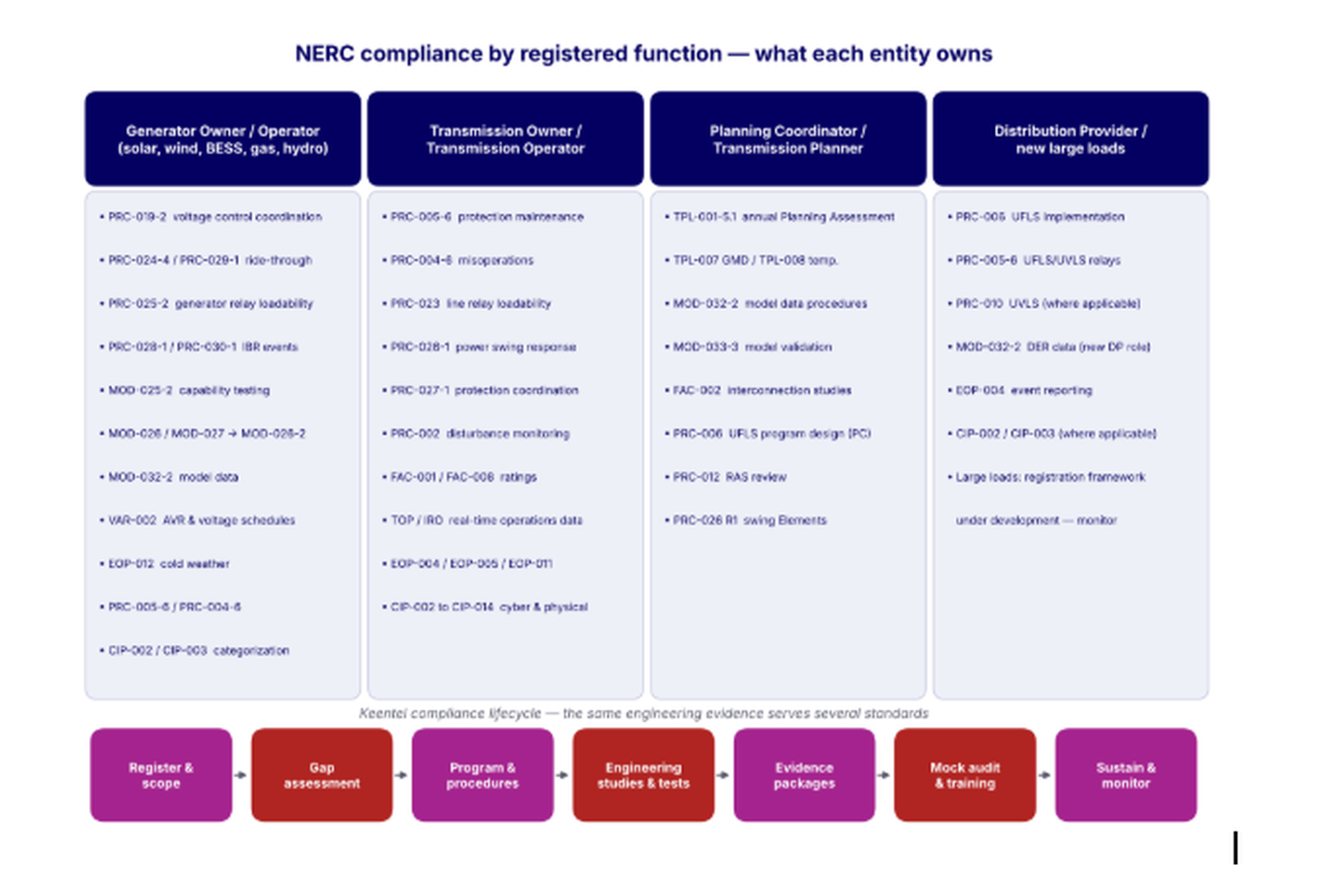
Figure 1. Keentel's map of the principal NERC standards by registered function, and the compliance lifecycle Keentel follows. Many engineering deliverables — a verified model, a relay settings review, a recorder — serve several standards at once.


The standards map


The table below summarizes the standards Keentel works with most often, the functions they apply to and the engineering that supports them. It is a guide, not a substitute for each standard's applicability section.

Standard Topic Primary functions Engineering behind it
PRC-002 Disturbance monitoring (non-IBR) TO, GO Recorder location and triggers, data retention
PRC-004-6 Protection System misoperation identification and correction TO, GO, DP Event analysis, root cause, corrective action plans
PRC-005-6 Protection System, Automatic Reclosing and Sudden Pressure Relaying maintenance TO, GO, DP Maintenance program, intervals, test procedures and records
PRC-006 Under-frequency load shedding PC (design), TO, DP (implement) UFLS design studies, relay settings
PRC-012 Remedial Action Schemes RC, PC, RAS-entity RAS design, reviews and functional tests
PRC-019-2 Coordination of generator voltage controls, limiters and protection GO Capability curve, limiter and relay coordination studies
PRC-023 Transmission relay loadability TO, GO, DP Loadability calculations for phase protective relays
PRC-024-4 Ride-through settings — synchronous and Type 1/2 wind GO Voltage and frequency protection settings review
PRC-025-2 Generator relay loadability GO, TO, DP Load-responsive relay settings checks
PRC-026-1 Relay performance during stable power swings PC (R1), TO, GO Swing screening against Attachment B; settings changes
PRC-027-1 Coordination of Protection Systems for performance during faults TO, GO, DP Coordination studies, fault current change tracking
PRC-028-1 IBR disturbance monitoring GO Recorder design, triggers, synchronization, data delivery
PRC-029-1 IBR ride-through GO Inverter, controller and protection settings; performance evidence
PRC-030-1 Unexpected IBR event mitigation GO Detection, root cause, corrective action plans
MOD-025-2 Real and reactive capability verification GO Staged tests or operational data, test reports
MOD-026 / MOD-027 → MOD-026-2 Dynamic model verification GO, TP Model building, staged tests, recordings, simulation comparisons
MOD-032-2 Modeling data PC, TP, GO, TO, DP, BA, RP, TSP Model data submittals, DER data
MOD-033-3 System model validation PC Steady-state and dynamic comparisons
TPL-001-5.1 Transmission system planning PC, TP Annual Planning Assessment, CAPs
FAC-001 / FAC-002 Interconnection requirements and studies TO, GO, PC, TP Interconnection requirements documents, studies
FAC-008 Facility Ratings TO, GO Ratings methodology and equipment ratings database
VAR-002 Generator voltage control GO, GOP AVR status, voltage schedules, GSU tap data
EOP-004 Event reporting Most functions Reporting procedures and timelines
EOP-011 / EOP-012 Emergency operations and cold weather preparedness TOP, BA, GO, GOP Freeze protection, cold weather data, corrective actions
CIP-002 to CIP-014 Cyber and physical security Most functions BES Cyber System categorization and controls
TOP / IRO Real-time operations and data specifications TOP, RC, BA, data providers Operational data and models

Eight findings from Keentel's compliance work


1. Most audit findings are evidence failures, not engineering failures. The work was done, but the records do not prove it, or they prove it for the wrong date, device or version.

2. Applicability is the first engineering decision. A wrong BES or Category 2 determination, or a missed relay in the PRC-025 population, undermines everything that follows.

3. The same data serves several standards. A recorder installed for PRC-028 feeds PRC-030 analysis, MOD-026 model verification and MOD-033 validation. Build one data architecture, not one per standard.

4. Settings in the field must match settings in the model. Ride-through, plant controller and protection settings appear in PRC-024/029 evidence, MOD-032 data and MOD-026 models. Mismatches are common and are increasingly visible to auditors and planners.

5. Change triggers compliance. Capacity additions, inverter firmware updates, relay replacements, CT ratio changes and new interconnections all have compliance consequences. Management of change is a compliance control.

6. Internal controls reduce oversight. Entities that can show how they prevent, detect and correct noncompliance receive lighter oversight and better outcomes when something goes wrong.

7. Self-reporting is almost always the better path. A possible violation found by your own controls and promptly reported and mitigated is treated far more favorably than one found by the Regional Entity.

8. Compliance programs need engineering owners. Every requirement with a technical basis needs a named engineer who understands it, not only a compliance coordinator who tracks it.


Key terms

Term Meaning
BES Bulk Electric System, as defined in the NERC Glossary, generally elements at 100 kV and above with inclusions and exclusions
Category 2 GO / GOP Owner or operator of non-BES IBRs of at least 20 MVA aggregate at a common point of 60 kV or above, registered under the revised criteria
CMEP Compliance Monitoring and Enforcement Program, NERC Rules of Procedure Appendix 4C
RSAW Reliability Standard Audit Worksheet — the auditor's evidence checklist
VRF / VSL Violation Risk Factor and Violation Severity Level for each requirement
CAP Corrective Action Plan
PSMP Protection System Maintenance Program under PRC-005-6
IBR Inverter-Based Resource, as defined in the NERC Glossary
DER Distributed Energy Resource, a new Glossary term introduced with MOD-032-2
Internal controls Documented activities that prevent, detect and correct noncompliance

Part B — Engineering Guide by Registered Function

Part B walks through the standards by registered function. Each section explains what the requirement asks for, the engineering that meets it, a worked example where calculation is involved, and the evidence an auditor will expect. Requirement summaries are paraphrased; the governing text is always the current approved standard.


1. Generator Owners and Generator Operators


Generator Owners (GOs) carry the largest number of technical requirements among registered functions, and IBR owners now carry the newest. The common theme is that the plant's settings, capabilities and models must be known, coordinated and proven.


1.1 PRC-019-2 — coordinating voltage controls, limiters and protection


PRC-019-2 requires the GO to verify that a generating unit's or plant's voltage regulating controls, limiters and protection are coordinated, so that protection does not trip the unit before the limiters have had a chance to act, and so that limiters keep the unit inside its capability. The verification must be repeated periodically and after changes that affect coordination; the standard sets the interval (at least once every five calendar years) and a deadline after equipment or setting changes. Confirm both against the current text.


For a synchronous machine, the classic checks are on the underexcited side: the underexcitation limiter (UEL) must operate before the loss-of-field relay (40) reaches its trip zone, and both must sit inside the steady-state stability limit and the machine capability curve. On the overexcited side, the volts-per-hertz limiter must operate before the volts-per-hertz relay (24), and the overexcitation limiter must protect the field before field overcurrent protection acts.


For an IBR plant, the logic is the same but the devices differ: the plant controller's reactive limits, the inverters' current and voltage limits, inverter AC overvoltage and undervoltage protection, collector and main power transformer protection, and any capacitor bank or STATCOM controls. The question is whether any protective function will act before the plant's own controls have had the chance to keep it inside its capability.


Worked example 2 — loss-of-field relay versus UEL

A 200 MVA, 18 kV synchronous generator has a UEL point at P = 0.80 pu and Q = −0.30 pu (absorbing) at 1.0 pu terminal voltage. The loss-of-field relay is an offset mho with offset X′d/2 = 0.15 pu and diameter Xd = 1.80 pu. Does the UEL operate before the relay?


Convert the UEL point to apparent impedance:

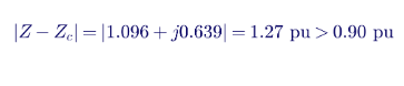
The relay circle is centered at −j(0.15 + 0.90) = −j1.05 pu with a radius of 0.90 pu. The distance from the UEL point to the center is:

The UEL point lies outside the relay circle with a margin of about 0.37 pu, so the limiter acts first. In secondary ohms, with a base impedance of 18² / 200 = 1.62 Ω and CT and VT ratios of 8000:5 and 18,000:120, the UEL point is about 20.2 Ω secondary. A complete PRC-019 study repeats the check across the capability curve, at minimum and maximum expected terminal voltage, and with the limiter and relay characteristics plotted on the same P–Q or R–X diagram.

Coordination pair Must operate first Typical evidence
UEL vs loss-of-field relay (40) UEL P–Q or R–X plot with both characteristics and capability curve
V/Hz limiter vs V/Hz relay (24) Limiter Time-overexcitation plot with limiter and relay curves
Overexcitation limiter vs field overcurrent protection Limiter Time–current plot of limiter and protection
Plant controller Q limits vs inverter and POI voltage protection (IBR) Controller limits Voltage–reactive power plot showing limits and trip settings
Inverter current limits vs collector protection (IBR) Inverter limits Time–current coordination plot

How Keentel Engineering helps here. Keentel performs PRC-019 coordination studies for synchronous and inverter-based plants, plotting limiter, relay and capability characteristics on common axes, documenting the settings source for each device and producing an RSAW-ready report with a change-trigger checklist.


1.2 PRC-024-4 and PRC-029-1 — ride-through


With Order No. 909, ride-through obligations split by technology. PRC-024-4 covers voltage and frequency protection settings of synchronous generators, Type 1 and Type 2 wind turbines and synchronous condensers. PRC-029-1 sets performance-based ride-through requirements for IBRs: the plant must remain connected and continue to operate through defined voltage and frequency excursions, with specific expectations for current injection and recovery, and with documentation of any equipment limitations that prevent full compliance.


The difference matters. PRC-024 is largely a settings standard: show that protective relays will not trip inside a no-trip zone. PRC-029 is a performance standard: show that the plant actually rides through, which brings in inverter firmware behavior, momentary cessation, phase-lock loop response, DC-link protection, plant controller interaction and post-fault overvoltage. Our article When LVRT Becomes HVRT in Weak Grids explains why a plant that rides through a voltage dip can still trip on the overvoltage that follows the fault.


Worked example 3 — settings screen against a ride-through envelope

A GO lists every voltage and frequency trip function in the plant: inverter undervoltage and overvoltage stages, collector feeder relays, main power transformer relays and any POI relays. For each function it records the pickup, time delay and measurement point, converts the pickup to per unit at the reference point the standard uses, and compares the setting with the envelope.

Function Measured at Pickup Delay Required no-trip envelope at that magnitude Result
Inverter UV stage 1 Inverter terminal 0.50 pu 0.16 s Must ride through longer at this magnitude (illustrative) Fails — extend delay or lower pickup
Inverter OV stage 2 Inverter terminal 1.20 pu 0.01 s Must ride through a short excursion above this level (illustrative) Review — terminal voltage exceeds POI voltage after fault clearing
Collector feeder 27 34.5 kV bus 0.70 pu 2.0 s Within envelope Pass
Plant 81U POI 57.0 Hz 0.1 s Below the no-trip frequency boundary for the Interconnection (verify) Pass if the boundary is above 57.0 Hz

The values above are illustrative; the governing curves, tables and measurement-point rules are those in the current PRC-024-4 and PRC-029-1 text for the relevant Interconnection. Two common errors deserve attention: comparing an inverter-terminal setting with a POI-referenced curve without accounting for the voltage difference across the main power transformer and collector system, and ignoring fast-acting inverter protection that is not visible in the relay settings database.


How Keentel Engineering helps here. Keentel builds a complete trip-function inventory, translates each setting to the standard's reference point, screens against the governing envelope, and runs EMT simulations where performance must be demonstrated. Where equipment limitations exist, we prepare the technical documentation PRC-029-1 requires.


1.3 PRC-025-2 — generator relay loadability


PRC-025-2 requires GOs (and TOs and DPs owning applicable relays) to set load-responsive protective relays associated with generator Facilities so that they do not trip during the high reactive output a generator delivers under stressed system conditions — for example, during field forcing after a nearby fault. Attachment 1 contains a table of options for each relay type and application (generator phase distance, GSU high-side overcurrent, unit auxiliary transformer protection, IBR collector and interconnection relays, and others). Each option prescribes the simulated real and reactive power, the voltage and the margin to use.


Worked example 4 — IBR interconnection overcurrent relay

A 230 MVA solar plant connects through a 34.5/138 kV transformer. A phase overcurrent relay on the 138 kV side protects the plant interconnection. Rated current at 138 kV is:

If the applicable Attachment 1 option requires the pickup to exceed 130% of the current at the plant's maximum aggregate nameplate output (an illustrative factor — confirm the exact multiplier, voltage and power basis in the option that applies to your relay), the pickup must exceed 1.30 × 962 ≈ 1,251 A primary. A relay set at 1,100 A primary would fail and must be raised, supervised or replaced with a function the standard treats differently.


The most common PRC-025 problems are not calculation errors. They are population errors: relays that were never identified as load-responsive, relays on auxiliary transformers that were overlooked, and IBR collector relays added after the original review.


How Keentel Engineering helps here. Keentel identifies the full load-responsive relay population from single-line diagrams and settings files, selects and documents the Attachment 1 option for each relay, performs the calculations and recommends setting changes that preserve fault sensitivity.


1.4 PRC-028-1 and PRC-030-1 — monitoring and event mitigation for IBRs


PRC-028-1 requires sequence-of-events, fault recording and dynamic disturbance recording at IBR plants, with defined locations, sampling, triggers, time synchronization, retention and data-delivery timelines. PRC-030-1 then requires the GO to detect unexpected changes in output — any complete loss of output, or any change in Real Power of at least 20 MW and at least 10% of gross nameplate within four seconds, excluding defined causes — analyze each event within 90 calendar days, develop a Corrective Action Plan or technical justification within 60 days of completing the analysis, and implement the CAP while keeping the RC informed.


The two standards depend on each other. A PRC-030 analysis is only as good as the data PRC-028 equipment captured. Our companion guides show why a four-second SCADA historian can miss a 215 MW momentary dip entirely, and why the PRC-030 threshold is the larger of 20 MW and 10% of nameplate, not the smaller.

Requirement Engineering deliverable
PRC-028 recorder design Recording locations, channels, sample rates, triggers and time synchronization specified per plant
PRC-028 data delivery Procedure and tested data path to provide records to the PC, TP, RC and others within the required time
PRC-030 R1 detection Documented algorithm, data source and resolution that can detect four-second changes
PRC-030 R2 analysis Root cause, ride-through and reactive response assessment, performance issues, fleet extent of condition
PRC-030 R3/R4 CAP Corrective actions, timetables, notifications to RC, BA and TOP

How Keentel Engineering helps here. Keentel designs PRC-028 monitoring architectures, writes PRC-030 detection procedures, and performs event analyses using recorder, inverter fault log and plant controller data, supported by PSCAD replication where root cause is not obvious.


1.5 MOD-025-2 — real and reactive power capability


MOD-025-2 requires GOs to verify and report the real and reactive power capability of their units and plants, typically through staged tests or qualifying operational data, within defined periods after commissioning and periodically thereafter. The capability reported is used by Transmission Planners and operators; an optimistic value can lead to voltage collapse in a study that should have flagged it.


Worked example 5 — reactive capability at the POI

A 150 MW solar plant has an interconnection requirement of 0.95 power factor leading and lagging at the POI at full output. The required reactive power is:

During the test the plant delivers 46.0 Mvar at the POI with POI voltage at 1.02 pu. Is that a failure? Not necessarily. The test must be evaluated against the conditions the requirement specifies; at higher POI voltage, transformer and collector reactive losses change and inverter terminal voltage approaches its upper limit, which caps output. The report should record the measured value, the test conditions, the limiting factor (inverter current, inverter terminal voltage, controller limit or transformer tap position) and, where the interconnection agreement requires it, a calculation projecting capability at the reference conditions. If the plant genuinely cannot deliver 49.3 Mvar at the reference condition, the shortfall must be resolved through settings, tap changes or added reactive equipment.


How Keentel Engineering helps here. Keentel writes MOD-025 test procedures, witnesses tests, analyzes data, identifies limiting elements and prepares capability reports that reconcile test results with the interconnection agreement and the planning model.


1.6 MOD-026 and MOD-027, moving to MOD-026-2 — dynamic model verification


MOD-026-1 (excitation and voltage control) and MOD-027-1 (turbine-governor and load control, or active power and frequency control) require GOs to provide verified dynamic models to their Transmission Planner and to re-verify them periodically. Under the Order No. 901 modeling package, MOD-026-2 replaces both standards with a single verification framework that explicitly covers IBRs and requires TP acceptance of the verified model. Check the current implementation plan for transition dates.


Verification compares model response with measured response. For an IBR plant, that typically means reproducing a recorded disturbance or a staged test — a reactive power or voltage step, a frequency excursion response, a fault ride-through event — in the positive-sequence model and, increasingly, in an EMT model. The acceptance criteria are set by the TP's requirements, and they usually include visual agreement of key quantities and numeric tolerances for steady-state values, rise time and settling.

Model element Typical verification evidence
Plant controller voltage or reactive control Reactive power step response at POI, measured versus simulated
Inverter fault response Recorded fault event, current injection during and after fault
Active power–frequency control Frequency excursion or staged droop test
Protection and ride-through representation Settings comparison between field and model
EMT model Benchmark against positive-sequence model and recorded data

How Keentel Engineering helps here. Keentel builds and tunes PSS®E, PSLF and PSCAD models, designs verification tests, benchmarks models against PRC-028 recordings and prepares MOD-026 packages that answer the TP's acceptance checklist. See MOD-033-3: System Model Validation and MOD-032-2: Data for Power System Modeling for how verified unit models feed system models.


1.7 MOD-032-2 — modeling data from the GO


Under MOD-032-2, GOs — including Category 2 GOs — provide steady-state, dynamic and short-circuit data according to the procedures their Planning Coordinator and Transmission Planner publish. Where a model accepted by the TP under MOD-026 exists, that is the model to submit. Our MOD-032-2 guide covers the dates, the DER definition and the Unacceptable Models List.


1.8 VAR-002 — voltage control


VAR-002 requires the Generator Operator to operate with the automatic voltage regulator (or the IBR plant's equivalent voltage control) in automatic voltage control mode unless otherwise directed, to maintain the voltage or reactive schedule the Transmission Operator provides, and to notify the TOP of status changes within defined times. The GO must provide step-up transformer tap and impedance data on request. Evidence is largely operational: logs, schedules, notifications and tap data.


1.9 EOP-012 — cold weather preparedness


After the February 2021 and December 2022 winter events, NERC developed EOP-012 to require GOs to implement freeze protection measures, provide cold weather data, maintain cold weather preparedness plans, train staff, and develop corrective action plans after freeze-related outages, derates or failures to start. Later versions refined the requirements for new and existing units. Verify which version is currently effective and its applicability to IBRs and storage in your region.


Worked example 6 — sizing heat tracing for an exposed line

A 2-inch instrument sensing line (outside diameter 2.375 in) has 2 inches of insulation with a thermal conductivity of 0.30 BTU·in/(h·ft²·°F). The plant must keep the line at 40 °F at a design extreme cold temperature of −10 °F, a temperature difference of 50 °F. Heat loss per foot is:

With a 20% margin for wind and aging, the design load is about 2.8 W/ft, so a 3 W/ft self-regulating cable is appropriate. The EOP-012 evidence is not just the calculation: it is the inventory of freeze-sensitive components, the design temperature basis, the installed measures, inspection records and the corrective action history.


How Keentel Engineering helps here. Keentel performs cold weather vulnerability assessments, freeze protection designs and EOP-012 evidence packages for thermal, wind, solar and storage plants.


1.10 CIP standards for generators


Every registered GO and GOP must categorize its BES Cyber Systems under CIP-002. Most renewable and storage plants fall in the low impact category and must implement a CIP-003 low impact plan covering cyber security awareness, physical security controls, electronic access controls, cyber security incident response, transient cyber asset and removable media controls, and vendor remote access where applicable. Larger facilities and control centers can be medium or high impact, which brings the full CIP-004 through CIP-013 suite. CIP-014 physical security applies to certain transmission stations and substations, not to generation as such.


Keentel's CIP work focuses on the engineering interfaces: network architecture drawings, identification of routable and dial-up connectivity, electronic access points, and categorization evidence. We coordinate with specialist cyber security firms where full CIP programs are required.


2. Transmission Owners and Transmission Operators


Transmission Owners (TOs) carry the bulk of the protection-related standards. Transmission Operators (TOPs) carry the real-time operations standards. Many utilities, cooperatives and municipal systems hold both registrations, and many generator interconnection facilities are owned by TOs even when the generator owner paid for them.


2.1 PRC-005-6 — Protection System maintenance


PRC-005-6 requires each TO, GO and DP to establish a Protection System Maintenance Program (PSMP) for its Protection Systems, Automatic Reclosing and Sudden Pressure Relaying, and to perform the minimum maintenance activities within the maximum intervals in the standard's tables, or under a performance-based program meeting Attachment A. The program must document, for each Component Type, whether maintenance is time-based, performance-based or a combination, and must justify any monitoring attributes used to extend intervals.

Component (examples) Typical maximum interval for unmonitored components Minimum activity (summary)
Microprocessor protective relays 6 calendar years Verify settings, operation of inputs and outputs, and acceptable measurement of power system values
Voltage and current sensing inputs 12 calendar years Verify the relay receives correct current and voltage signals
Protection System communications 4 calendar months (inspection) and 6 calendar years (performance) Verify channel operation and performance
Station dc supply — vented lead-acid 4 calendar months, 18 calendar months and 6 calendar years for different activities Inspections, internal ohmic or capacity testing as specified
Trip coils and unmonitored control circuitry 6 and 12 calendar years Verify trip coils operate; verify trip paths
Sudden pressure relays and their lockouts 6 calendar years Verify sensing mechanism and electrical operation
Automatic Reclosing and UFLS/UVLS relays Per the applicable tables Verify operation and settings

The intervals above are summaries for orientation; the standard's tables govern, and monitoring attributes change several of them. Our guide Buchholz and Sudden Pressure Relays under PRC-005-6 covers Table 5 in detail.


Worked example 7 — scheduling a PSMP workload

A mid-sized TO has 1,240 unmonitored microprocessor relays (6-year interval), 1,240 sets of voltage and current sensing inputs (12-year interval), 410 unmonitored control circuits (12-year interval) and 62 vented lead-acid station batteries with 18-month activities.

Component group Count Interval Per year at the maximum Planning target (finish each cycle at 85% of the interval)
Microprocessor relays 1,240 6 years 207 About 243
Sensing inputs 1,240 12 years 103 About 122 (combine with relay tests)
Control circuitry 410 12 years 34 About 40
Station batteries (18-month activities) 62 18 months 41 About 49

Planning to complete each cycle at about 85% of the maximum interval gives a buffer for cancelled outages, storms and equipment replacement. The single most common PRC-005 violation Keentel sees in mock audits is not an overdue relay test — it is a component that was never in the PSMP population at all, often an auxiliary relay, a lockout, a communications channel or a battery at a remote site.


How Keentel Engineering helps here. Keentel writes PSMPs, builds component inventories from drawings and field verification, develops test procedures, reviews test records against the minimum activities and intervals, and performs mock audits against the PRC-005 RSAW.


2.2 PRC-004-6 — misoperations


PRC-004-6 requires TOs, GOs and DPs to identify whether each operation of a Composite Protection System is a Misoperation, within 120 calendar days of the interrupting device operation, then to identify the cause and develop and implement a Corrective Action Plan, with defined timelines and extent-of-condition evaluation. A Misoperation can be a failure to trip, a slow trip, an unnecessary trip during a fault, or an unnecessary trip with no fault.


Good PRC-004 work depends on data: relay event reports, oscillography, sequence-of-events records and settings in force at the time. Keentel analyzes events with COMTRADE records, settings files and short-circuit models, determines whether the operation was correct, and writes CAPs that address the root cause and the extent of condition.


2.3 PRC-023 — transmission relay loadability


PRC-023 requires phase protective relays on transmission lines and transformers to be set so they do not operate at defined load levels, so that relays do not trip heavily loaded lines during stressed conditions and contribute to cascading. The most common criterion for a line is that the relay must not operate at 150% of the highest seasonal four-hour Facility Rating with the line-to-line voltage at 0.85 per unit and a load angle of 30 degrees.


Worked example 8 — zone 3 loadability on a 345 kV line

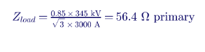
A 345 kV line has a highest seasonal four-hour Facility Rating of 2,000 A. The loadability criterion sets the test current at 150% of 2,000 A, or 3,000 A, at 0.85 per unit voltage. The equivalent load impedance is:

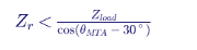
A mho element with maximum torque angle θ_MTA reaches a distance Z_r cos(θ_MTA − 30°) along the 30° load line. To stay outside the load point:

Maximum torque angle Maximum mho reach
75° 79.8 Ω
80° 87.8 Ω
85° 98.4 Ω

A zone 3 element set to 110 Ω at 85° reaches 63.1 Ω along the 30° load line, which is beyond the 56.4 Ω load point. It fails. The options are to reduce the reach to below 98.4 Ω, apply load encroachment blinders that cut the load region out of the characteristic, convert to a quadrilateral characteristic with a resistive reach below the load point, or — if remote backup is truly needed — use a different scheme. Each option has consequences for remote backup coverage that must be documented.


How Keentel Engineering helps here. Keentel performs PRC-023 reviews for lines and transformers, plots relay characteristics against the load point, recommends load encroachment or characteristic changes, and documents the criteria used for each relay.


2.4 PRC-026-1 — power swings


PRC-026-1 requires the Planning Coordinator to identify Elements exposed to power swings and notify the owners, and requires TOs and GOs to evaluate load-responsive protective relays on those Elements against Attachment B criteria, then develop and implement Corrective Action Plans where a relay could trip on a stable power swing. Our guide Power Swing Blocking and NERC PRC-026 works through the screening in detail: on the 345 kV, 100-mile example line, a mho zone 2 at 125% of line impedance is entered by the swing at about 109° and fails the screen, while a quadrilateral with resistive blinders within about ±20 Ω passes. The evaluation, the CAP and the evidence trail are all engineering products.


2.5 PRC-027-1 — protection coordination


PRC-027-1 requires TOs, GOs and DPs to have a process for developing new and revised Protection System settings for BES Elements that includes reviewing and coordinating settings with neighboring entities, and to perform periodic Protection System Coordination Studies or to monitor short-circuit changes and restudy when fault current changes beyond a threshold. The standard offers options for the periodic obligation; verify the current interval and the fault-current change threshold in the text you are complying with.


The engineering behind PRC-027 is a maintained short-circuit model that reflects new generation (including IBRs with limited fault current), transmission changes and neighboring systems, and a settings database that ties each relay to the study that justified it. IBR additions are now the most common reason that a previously coordinated scheme needs to be re-examined: inverter fault current is limited and controlled, negative-sequence current may be small or may follow IEEE 2800 requirements, and ground source contributions depend on transformer connections. Our Ground Distance Protection guide explains how these effects change zone reach and polarization.


2.6 FAC-001, FAC-002 and FAC-008


FAC-001 requires TOs (and certain GOs) to document and publish Facility interconnection requirements for generation, transmission and end-user Facilities. FAC-002 requires coordinated studies of new or materially modified Facilities. FAC-008 requires a documented Facility Ratings methodology and ratings for each Facility, determined by the most limiting equipment — conductor, transformer, breaker, switch, CT, wave trap, jumper or relay setting.


FAC-008 findings are common and often expensive because the error lies in the field: a CT tap that limits a rating, a substation jumper that was never updated after a reconductoring, or a relay loadability limit that was not carried into the rating. Keentel performs ratings walkdowns, builds ratings databases and reconciles them with relay settings, PRC-023 calculations and the planning model.


2.7 Operations, events and security


TOPs operate under TOP and IRO standards for real-time monitoring, operating plans, data specifications and coordination with the Reliability Coordinator; EOP-004 governs event reporting; EOP-005 and EOP-006 govern system restoration; EOP-011 governs emergency operations; CIP-002 through CIP-014 govern cyber and physical security. Keentel's role here is engineering support: studies for operating plans and restoration, event analysis, and the technical inputs that operations standards depend on.


3. Planning Coordinators and Transmission Planners


Planning Coordinators (PCs) and Transmission Planners (TPs) own the standards that decide how the system will perform in the future, and they increasingly own the processes that collect data from everyone else.


3.1 TPL-001-5.1 — the annual Planning Assessment


TPL-001-5.1 requires each PC and TP to prepare an annual Planning Assessment of its portion of the BES covering the Near-Term (years one through five) and Long-Term (years six through ten) horizons, using steady-state, short-circuit and Stability studies of the planning events (P0 through P7) and extreme events in Table 1, and to develop Corrective Action Plans when performance requirements are not met.

Category Event (summary) Typical fault type
P0 No contingency —
P1 Single contingency (generator, line, transformer, shunt, DC pole) 3Ø for elements, SLG for DC
P2 Single event: line section opening, bus section fault, internal breaker fault SLG
P3 Generator out followed by a single contingency 3Ø
P4 Stuck breaker during a fault SLG
P5 Protection system failure (non-redundant component) SLG
P6 Two overlapping single contingencies 3Ø
P7 Common structure or bipolar DC SLG

Our TPL-001-5.1 guide covers each requirement, footnote 12 non-consequential load loss, sensitivity cases, the treatment of protection system single points of failure and the annual cycle.


3.2 MOD-032-2 and MOD-033-3 — data and validation


Under MOD-032-2, the PC and TP must jointly develop and publish data requirements and reporting procedures that now explicitly cover IBRs, DERs and the new Distribution Provider role. Under MOD-033-3, the PC must implement a documented Model Validation process comparing steady-state simulation with actual system behavior and dynamic simulation with recorded disturbances at least once every 24 calendar months. Our dedicated guides cover both standards in depth.


3.3 PRC-006, PRC-012 and PRC-026 R1


The PC designs the under-frequency load shedding program under PRC-006 and assesses it periodically through dynamic simulation. PCs and RCs review Remedial Action Schemes under PRC-012. Under PRC-026 R1, the PC identifies Elements for evaluation — for example, Elements that form a boundary of an island in a UFLS design assessment, Elements with relays that tripped on stable or unstable power swings, and Elements identified in Planning Assessments as monitored for angular stability — and notifies the owners. Each of these obligations depends on validated dynamic models.


How Keentel Engineering helps here. Keentel supports PCs and TPs with Planning Assessment studies, contingency analysis, stability and EMT studies, Corrective Action Plan development, MOD-032 procedure drafting, MOD-033 validations, UFLS assessments and PRC-026 Element identification.


4. Distribution Providers and DER


Distribution Providers (DPs) typically carry PRC-005-6 maintenance for UFLS and UVLS relays, PRC-006 implementation of the UFLS program designed by the PC, PRC-004 for applicable Protection Systems, and EOP-004 event reporting. MOD-032-2 adds a new obligation: DPs now provide DER data under their PC's procedures, including aggregate DER capacity and, where available, ride-through and trip settings. The drafting team set no size threshold for DER, so DPs need practical methods to estimate data they cannot measure, and must explain the method.


UFLS design is becoming harder as DER grows: a feeder that sheds load during an under-frequency event may also shed rooftop solar, so the net load removed can be much smaller than planned. Keentel helps DPs and PCs quantify net load at UFLS feeders and adjust programs accordingly.


5. New large loads


For data centers and other large loads, NERC obligations arrive indirectly but firmly. The TO's FAC-001 interconnection requirements, the PC's MOD-032 data procedures and the TP's TPL-001 and FAC-002 studies all reach the load. Utilities increasingly ask large-load customers for dynamic models, ride-through capability for voltage dips, protection settings that avoid simultaneous disconnection, power quality data, and the behavior of on-site generation and storage.

Topic What utilities ask large loads for Engineering response
Model data Load composition, dynamic models, UPS and power supply behavior Models built from equipment data and tests
Ride-through Behavior during faults and voltage dips on the transmission system Ride-through studies and UPS/power supply settings review
Protection Settings that avoid tripping on transmission faults cleared normally Protection coordination with the utility
Power quality Harmonics, flicker, unbalance IEEE 519 studies and mitigation
On-site generation and storage Interconnection and operating characteristics Studies under the generator interconnection process where applicable

How Keentel Engineering helps here. Keentel performs large-load interconnection studies, builds load models, reviews ride-through and protection behavior, and prepares the technical packages utilities require — with an eye on the registration framework NERC is developing.


6. How Keentel delivers a compliance program


Keentel's approach follows the lifecycle in Figure 1 and is the same whether the client is a single solar plant, a fleet owner or a utility.

Keentel's dedicated NERC compliance team works alongside our protection, studies and design engineers, so the person who writes the procedure can call on the person who runs the study. Clients receive regular status updates and a single point of contact for each engagement.


Part C — Three Anonymous US Case Studies

The case studies below are composites drawn from the types of engagement Keentel performs. Names, locations and some figures have been changed or generalized to protect client confidentiality.


Case study 1 — A newly registered Category 2 solar owner


Situation. An independent power producer owned four solar plants of 22 to 60 MVA in the Southwest, each connected at 69 kV or 115 kV. None had previously been registered with NERC. Under the revised registration criteria, the owner registered as a Category 2 Generator Owner and Generator Operator and asked Keentel to determine what it now had to do and by when.


What Keentel found. The applicability review showed that one 60 MVA plant was only a few megavolt-amperes below the 75 MVA BES threshold, and a planned 20 MVA storage addition behind the same 115 kV transformer would make it a BES facility. A second plant was registered on the basis of 22 MVA nameplate, but the inverter nameplate schedule supplied to the registration team used a site rating that excluded two inverters added during construction; the correct figure was 24.4 MVA. Neither error changed the registration outcome, but both would have changed the facility applicability memos and the recorder design.


The settings review found that inverter undervoltage stages at three plants were set with short delays inherited from a distribution-style interconnection specification. Screened against the ride-through envelope at the correct reference point, two of the stages failed. The plant controllers had no defined freeze or hold behavior during faults, and none of the plants had recording capable of resolving a four-second output change.


What Keentel delivered.


  • Facility applicability memos for each standard, with single-line diagrams, nameplate schedules and POI voltage evidence.
  • A ride-through settings inventory and screen, coordinated with the inverter manufacturer, and an implementation plan for settings changes with test evidence.
  • A PRC-028 monitoring design for each plant and a PRC-030 detection procedure using high-resolution recorder data.
  • A compliance calendar with change triggers, including the BES re-evaluation for the planned storage addition.
  • Training for the operations center and site staff on VAR-002 notifications and EOP-004 reporting.


Outcome. The owner entered its first compliance cycle with documented applicability, corrected settings and a monitoring design in its construction schedule. The storage addition was redesigned to include BES-level obligations from the start rather than as a retrofit.


Case study 2 — A transmission owner's PRC-005 mock audit


Situation. A municipal utility with 115 kV and 230 kV facilities faced an upcoming Regional Entity audit. Its PRC-005 records were kept in spreadsheets maintained by two relay technicians, one of whom had recently retired. The utility asked Keentel to perform a mock audit.


What Keentel found. The PSMP document was sound, but the component inventory did not match the field. Keentel reconciled the inventory against relay settings files, substation drawings and a sample of field walkdowns. The reconciliation found 23 components not in the program: lockout relays at two substations, communications channels for a permissive overreaching transfer trip scheme, station batteries at a remote switching station and voltage sensing inputs for a recently replaced relay panel. Six relays had test records with no evidence that the outputs had been verified through to the trip coil or lockout; four test reports recorded the wrong relay serial number after a panel replacement. Two sudden pressure relays were tested by operating the test button only, which did not verify the pressure sensing mechanism.


What Keentel delivered.


  • A reconciled component inventory linked to drawings, with monitoring attributes documented for each Component Type.
  • Updated test procedures for lockouts, communications and sudden pressure relays, specifying how to verify each minimum activity.
  • A prioritized remediation schedule completed before the audit window, with self-logging recommendations for the possible violations found.
  • An evidence repository organized in RSAW order, and interview preparation for the relay supervisor.

Outcome. The utility self-reported the gaps with completed mitigation before the audit. The audit closed with no additional PRC-005 findings, and the Regional Entity noted the reconciled inventory and change controls as a positive internal control.


Case study 3 — A battery storage plant event under PRC-028 and PRC-030


Situation. A 200 MW, 800 MWh battery storage plant in the south-central US was discharging at 160 MW when a 345 kV line fault occurred about 30 miles away. Plant output dropped to near zero during the fault and recovered to only 95 MW for several minutes. The owner asked Keentel to determine whether the event was reportable under PRC-030-1 and to analyze it.


What Keentel found. The PRC-030 threshold for a 200 MW plant is the larger of 20 MW and 10% of 200 MW, so 20 MW governs. The sustained 65 MW loss clearly qualified. Recorder data showed the fault cleared in four cycles with POI voltage recovering to about 1.12 pu for roughly 200 ms. Inverter fault logs showed that 21 of 52 power conversion systems tripped on a DC-link overvoltage alarm about 30 ms after fault clearing. The plant controller had wound up during the fault and commanded maximum reactive output on recovery, which pushed inverter terminal voltages higher and coincided with the DC-link overshoot.


A PSCAD replication with the manufacturer's model reproduced the trips. Two changes — a controller freeze extended slightly beyond fault clearing, and a revised DC chopper setting supplied by the manufacturer — eliminated them in simulation across a range of fault locations and grid strengths. The extent-of-condition review identified two other plants in the owner's fleet with the same power conversion system firmware and controller logic.


What Keentel delivered.


  • The PRC-030 R2 analysis report within the 90-day window, including root cause, ride-through assessment, reactive response and extent of condition.
  • A Corrective Action Plan with settings changes, firmware update, field verification test and timetable, transmitted to the RC, BA and TOP.
  • An updated MOD-026 model reflecting the new settings, and a note to the TP for the next MOD-032 submittal.
  • Recommendations for PRC-028 recorder trigger improvements after the event revealed a gap in DC-side data.


Outcome. The CAP was implemented across three plants within the stated timetable. A later fault of similar severity produced no trips, and the recorded response matched the updated model closely enough to support MOD-026 verification.


Part D — Technical FAQ: 30 Questions on NERC Compliance

The questions below are the ones owners, designers, operators and inspectors ask most often about 800 VDC and 1,500 VDC distribution. Each answer stands on its own, so some points from Parts A and B are repeated where they are needed to answer the question completely.

  • 1. How do I know whether my plant must register with NERC?

    Apply the registration criteria in Appendix 5B of the NERC Rules of Procedure. A generator generally must register if it is part of the BES — for example, units above 20 MVA, or dispersed generating resources above 75 MVA aggregate connected at 100 kV or above — or, under the revised criteria, if it is a non-BES IBR that has or contributes to an aggregate nameplate of at least 20 MVA delivered through a system designed primarily for that purpose to a common point of connection at 60 kV or above. Document the analysis with single-line diagrams and nameplate data, and confirm with your Regional Entity when in doubt.


  • 2. What is the difference between registration and applicability?

    Registration determines whether your organization is a registered entity for a function such as GO or GOP. Applicability determines which facilities and which requirements of each standard apply. A registered GO can own plants that fall outside a specific standard, and a Category 2 GO is subject only to the standards whose applicability sections include Category 2 facilities. Keep a facility-by-facility applicability memo for each standard.


  • 3. Which standards apply to a Category 2 Generator Owner?

    Category 2 GOs are subject to a defined set of standards, notably the Order No. 901 IBR standards such as PRC-028-1, PRC-029-1 and PRC-030-1, the modeling standards MOD-032-2 and MOD-026-2, and other standards whose applicability sections name Category 2 facilities. Implementation plans set phased dates. Because the list is defined standard by standard and may change as new standards are approved, maintain a standards matrix and review it whenever NERC adopts or FERC approves a standard.


  • 4. When did PRC-030-1 take effect?

    As set out in Keentel's PRC-030-1 guide, the standard became effective for BES IBRs on October 1, 2026, the later of the dates calculated from FERC's February 20, 2025 approval of PRC-030-1 and its July 24, 2025 approval of PRC-029-1. Applicable non-BES IBRs comply from January 1, 2027. Record the basis of your calculation and confirm with your Regional Entity.


  • 5. What triggers a PRC-030-1 analysis?

    A complete loss of facility output, or a change in Real Power of at least 20 MW and at least 10% of gross nameplate within four seconds, excluding the causes listed in the standard, or a request from the RC, BA or TOP. The larger of 20 MW and 10% governs, so for plants above 200 MW the 10% value applies.


  • 6. Is a four-second SCADA scan good enough for PRC-030-1 detection?

    Often not. A four-second scan can split a ramp across two samples or miss a momentary dip entirely. The detection process must be able to resolve the changes the standard describes. High-resolution recorder data or a purpose-built detection algorithm is usually needed, and the detection method should be documented and tested.


  • 7. What is the difference between PRC-024-4 and PRC-029-1?

    PRC-024-4 applies to synchronous generators, Type 1 and Type 2 wind turbines and synchronous condensers and focuses on protection settings that must not trip within defined voltage and frequency boundaries. PRC-029-1 applies to IBRs and sets performance-based ride-through requirements: the plant must stay connected and operate through defined excursions, with documentation of any equipment limitations.


  • 8. Can a plant comply with PRC-029-1 by changing relay settings only?

    Rarely. Ride-through performance depends on inverter firmware, phase-lock loop behavior, DC-link protection, momentary cessation logic, plant controller interaction and post-fault overvoltage. Settings changes are necessary but not always sufficient. EMT studies and manufacturer engagement are often needed to demonstrate performance.


  • 9. What does PRC-019-2 require for an IBR plant?

    It requires the GO to verify that voltage regulating controls, limiters and protection are coordinated. For an IBR plant, that means showing that the plant controller's reactive and voltage limits and the inverters' current and voltage limits act before protective functions trip the plant, across the plant's capability. The verification must be repeated periodically and after relevant changes.


  • 10. Which relays are in scope of PRC-025-2?

    Load-responsive protective relays associated with generator Facilities that could trip during high reactive output under stressed conditions, as listed in the standard's applicability and Attachment 1 — for example, generator phase distance and overcurrent relays, GSU and unit auxiliary transformer relays, and relays on IBR collector and interconnection Facilities. Population errors are the most common problem, so start with drawings and settings files rather than an existing list.

  • 11. How is PRC-023 loadability calculated for a line?

    For the most common criterion, the relay must not operate at 150% of the highest seasonal four-hour Facility Rating with voltage at 0.85 per unit and a load angle of 30 degrees. Calculate the load impedance at those conditions and compare it with the relay characteristic along the 30° line. For a mho element, the reach along the load line is the setting multiplied by the cosine of the angle between the maximum torque angle and 30°.


  • 12. What is a Protection System Maintenance Program?

    A documented program under PRC-005-6 that identifies each Component Type, states whether maintenance is time-based, performance-based or a combination, documents monitoring attributes used to justify intervals, and includes the procedures used to perform the minimum maintenance activities. It must cover Protection Systems, Automatic Reclosing and Sudden Pressure Relaying within scope.


  • 13. What are the most common PRC-005 audit findings?

    Components missing from the program, test records that do not prove every minimum activity, records with wrong device identification after replacements, missed intervals at remote sites, and sudden pressure or lockout tests that verify only part of the required function. Inventory reconciliation against drawings and the field prevents most of these.


  • 14. Can PRC-005 intervals be extended?

    Yes, through monitoring attributes that the tables recognize, or through a performance-based program under Attachment A, which requires segments of at least 60 Components, annual testing of a defined sample and Countable Events below 4%. Performance-based programs need careful statistics and recordkeeping.


  • 15. What counts as a Misoperation under PRC-004-6?

    A failure to trip, a slow trip, an unnecessary trip during a fault or an unnecessary trip other than during a fault, by a Composite Protection System. The entity must identify whether an operation was a Misoperation within 120 calendar days of the interrupting device operation, then identify the cause and develop and implement a Corrective Action Plan.


  • 16. How does PRC-026-1 work?

    The Planning Coordinator identifies Elements exposed to power swings and notifies the owners. The TO or GO then evaluates load-responsive protective relays on those Elements against Attachment B criteria, and develops and implements a Corrective Action Plan for relays that could trip on a stable power swing. Keentel's PRC-026 guide includes a worked Attachment B screening.


  • 17. How often must PRC-027 coordination studies be performed?

    PRC-027-1 offers options: a periodic coordination study at a fixed interval, monitoring of fault current changes with a restudy when changes exceed a threshold, or a combination. Confirm the interval and threshold in the current text. Large IBR additions and transmission changes are common triggers for restudy.


  • 18. What does MOD-025-2 require?

    Verification and reporting of real and reactive power capability of generating units and plants, by staged test or qualifying operational data, within defined periods after commissioning and periodically thereafter. Reports should record test conditions and limiting factors, and reconcile results with interconnection requirements and planning models.


  • 19. What is changing with MOD-026-2?

    MOD-026-2 consolidates dynamic model verification of voltage control and active power–frequency control into one standard that explicitly covers IBRs and requires Transmission Planner acceptance of verified models. It replaces MOD-026-1 and MOD-027-1 on the schedule set by its implementation plan. Owners should expect verification to rely increasingly on recorded disturbances from PRC-028 equipment.


  • 20. What data do Generator Owners provide under MOD-032-2?

    Steady-state, dynamic and short-circuit data required by the PC and TP's published procedures, including IBR plant models, ride-through settings and, where accepted, the MOD-026 verified model. Category 2 GOs are included. The submittal schedule and format are set by the procedures.


  • 21. What are Distribution Providers' new obligations under MOD-032-2?

    DPs provide DER data according to the PC and TP's procedures, including estimates where measured data are unavailable, with an explanation of the estimation method. The new Glossary definition of DER has no size threshold, so DPs need practical aggregation and estimation methods.


  • 22. What is a TPL-001 Corrective Action Plan?

    A list of actions and timetables to meet performance requirements where the Planning Assessment shows they are not met — for example, transmission upgrades, Remedial Action Schemes, operating procedures, or, within limits, non-consequential load loss under footnote 12. CAPs are reviewed in subsequent assessments.


  • 23. What does EOP-012 require of generators?

    Freeze protection measures, cold weather data, cold weather preparedness plans, training and corrective action plans after freeze-related outages, derates or failures to start, with requirements that differ for new and existing units. Verify the currently effective version and its applicability to your technology.


  • 24. Do CIP standards apply to solar and storage plants?

    Every registered GO and GOP must categorize its BES Cyber Systems under CIP-002. Most renewable and storage plants are low impact and must implement a CIP-003 low impact plan. Some larger facilities and control centers are medium or high impact. Network architecture, remote access and transient cyber asset controls are the usual focus.


  • 25. What evidence will an auditor ask for?

    The evidence listed in the RSAW for each requirement: programs and procedures with version history, records showing activities were performed within required timelines, studies and calculations supporting settings, notifications and transmittals with dates and recipients, and evidence of corrective actions. Evidence must cover the full audit period.


  • 26. Should we self-report a possible violation?

    In most cases, yes. A possible violation identified by your own internal controls, promptly reported or self-logged where eligible, and promptly mitigated is treated far more favorably than one discovered by the Regional Entity. Seek legal and regulatory advice on the specific circumstances.


  • 27. What are internal controls in NERC compliance?

    Documented activities that prevent, detect and correct noncompliance — for example, a change-management checklist that triggers PRC-025 and PRC-027 reviews when settings change, or a calendar that flags PRC-005 components well before their maximum interval. Regional Entities consider internal controls in setting oversight plans and penalties.


  • 28. How do large data centers fit into NERC compliance today?

    Large loads are not yet subject to a dedicated registration category, but NERC is evaluating one. Today, obligations reach large loads through the TO's interconnection requirements, the PC's data procedures and the TP's studies, and through interconnection agreements. Utilities increasingly require models, ride-through behavior, protection coordination and power quality studies.


  • 29. How long does it take to build a compliance program for a new registrant?

    For a small Category 2 owner with a few plants, a focused program — applicability, standards matrix, key procedures, settings screens and monitoring design — typically takes a few months. Studies, tests and equipment changes may extend over a longer period, aligned with implementation plan dates. Starting early avoids rushed changes near compliance dates.


  • 30. What does Keentel provide that a compliance software tool does not?

    Software tracks tasks and stores evidence. Keentel produces the engineering evidence itself — relay loadability calculations, ride-through screens, coordination studies, verified models, event analyses, test procedures — and organizes it so it answers the auditor's questions. Many clients use both: a tool for tracking, and Keentel for the engineering.


How Keentel Engineering Helps

Keentel Engineering provides NERC compliance services backed by power system engineering, from 4 kV to 765 kV. Our dedicated NERC compliance team works with our protection, studies, modeling and design engineers, so every procedure has an engineer behind it and every calculation lands in an audit-ready package.

Step What we do Deliverable
Register and scope Confirm registrations, BES and Category 2 status, facility applicability for each standard Applicability memo per facility, standards matrix
Gap assessment Compare existing programs, settings, models and records with each requirement and RSAW Gap register ranked by risk and effort
Program and procedures Write or update programs (PSMP, PRC-030 detection procedure, MOD-032 data procedure, PRC-019/025/026/027 processes) Controlled procedures with owners and triggers
Engineering studies and tests Perform the calculations, studies, tests and models each requirement needs Study reports, test reports, verified models
Evidence packages Organize evidence by requirement in RSAW order with cross-references Audit-ready evidence binders or repositories
Mock audit and training Conduct an audit simulation with interviews; train staff and subject matter experts Findings report, training records
Sustain and monitor Calendar, change triggers, periodic reviews, regulatory watch Compliance calendar, change checklist, monthly status

Typical engagement models:


  • Program build for newly registered entities: applicability, standards matrix, procedures, settings screens and monitoring design.
  • Audit readiness: gap assessment, evidence organization and mock audit, typically starting six to nine months before the audit window.
  • Standard-specific projects: PRC-019, PRC-023, PRC-025, PRC-026, PRC-027, MOD-025 and MOD-026 studies and tests.
  • Event response: PRC-004 and PRC-030 analyses and Corrective Action Plans within the required clocks.
  • Ongoing compliance support: periodic reviews, change-trigger evaluations and status updates to management.


Why Clients Choose Keentel


  • Engineering-led compliance. Our compliance work is performed by engineers who run the studies, set the relays and build the models, so the evidence is technically sound.
  • Full voltage range. 4 kV to 765 kV, distribution through EHV transmission, synchronous and inverter-based generation, and large loads.
  • IBR expertise. Ride-through, plant controllers, EMT modeling, event analysis and the Order No. 901 standards are core to our practice.
  • Audit-ready deliverables. Evidence organized by requirement in RSAW order, with clear cross-references and version control.
  • Responsive delivery. We work to compliance clocks — 60, 90 and 120-day deadlines — and to audit schedules.
  • Practical recommendations. Settings changes and corrective actions ranked by reliability benefit, cost and outage impact.
  • Credentials. Florida-registered professional engineering firm with offices in Tampa, Austin, Sacramento and Baltimore; NSPE member; IEEE Senior Member leadership; D-U-N-S registered; BBB Accredited Business A+.


Contact Keentel Engineering


Newly registered, preparing for an audit, responding to an event or evaluating relays under PRC-023, PRC-025 or PRC-026? Talk to our NERC compliance team.


  • Phone: (813) 389-7871
  • Email: contact@keentelengineering.com
  • Book a 15-minute call: calendly.com/keentel-engineering/15min
  • Web: keentelengineering.com


References


  • NERC Rules of Procedure, Appendix 4C, Compliance Monitoring and Enforcement Program; Appendix 5B, Statement of Compliance Registry Criteria (current editions, including revisions for Category 2 IBR registration).
  • NERC, Glossary of Terms Used in NERC Reliability Standards, including the definitions of Bulk Electric System, Inverter-Based Resource and Distributed Energy Resource.
  • NERC Reliability Standards PRC-002-5, PRC-004-6, PRC-005-6, PRC-006, PRC-012, PRC-019-2, PRC-023, PRC-024-4, PRC-025-2, PRC-026-1, PRC-027-1, PRC-028-1, PRC-029-1 and PRC-030-1, with Reliability Standard Audit Worksheets and implementation plans.
  • NERC Reliability Standards MOD-025-2, MOD-026-1, MOD-026-2, MOD-027-1, MOD-032-2 and MOD-033-3, with implementation plans.
  • NERC Reliability Standards TPL-001-5.1, TPL-007, TPL-008, FAC-001, FAC-002, FAC-008, VAR-002, EOP-004, EOP-011, EOP-012 and CIP-002 through CIP-014.
  • FERC Order No. 901, Reliability Standards to Address Inverter-Based Resources, October 19, 2023.
  • FERC Order No. 909, approving PRC-029-1 and PRC-024-4, July 24, 2025.
  • FERC letter order approving PRC-028-1, PRC-002-5, PRC-030-1 and the IBR definition, February 20, 2025.
  • FERC Order No. 818, approving PRC-026-1.
  • NERC disturbance reports on IBR performance (Blue Cut Fire, Canyon 2 Fire, Odessa and subsequent events) and NERC Large Loads Task Force publications.
  • IEEE Std 2800-2022, interconnection and interoperability of IBRs with transmission systems; IEEE Std C37.113 (line protection); IEEE Std C37.102 (generator protection); IEEE Std 519-2022 (harmonic control).
  • Keentel Engineering technical guides: PRC-030-1, PRC-028-1, MOD-032-2, MOD-033-3, TPL-001-5.1, Power Plant Controller Compliance, Power Swing Blocking and NERC PRC-026, Ground Distance Protection, Buchholz and Sudden Pressure Relays under PRC-005-6, and When LVRT Becomes HVRT in Weak Grids.


Disclaimer


This article is provided by Keentel Engineering for general technical education. It is not legal advice, and it is not engineering advice for any specific facility or compliance program. Requirement summaries are paraphrased; the governing text is the current FERC-approved version of each standard. Standard versions, effective dates, intervals, thresholds and penalty amounts change over time — verify each against the current NERC standard, implementation plan, Rules of Procedure and FERC order, and confirm interpretations with your Regional Entity and counsel. Worked examples use illustrative values. Case studies are composites. Keentel Engineering accepts no liability for decisions made on the basis of this article without a project-specific review.

© 2026 Keentel Engineering. All rights reserved. Written by Keentel Engineering.


Office Address Phone
Head Office — Tampa 400 N Ashley Dr STE #2600, Tampa FL 33602 (813) 389-7871
Austin 5900 Balcones Drive STE 100, Austin TX 78731 (512) 591-0752
Sacramento 1401 21st St Ste R, Sacramento CA 95811 (916) 913-4524
Baltimore 306 W Redwood St STE 200, Baltimore MD 21201 (410) 225-2181


A smiling man with glasses and a beard wearing a blue blazer stands in front of server racks in a data center.

About the Author:

Sandip "Sonny" R. Patel, P.E.

IEEE Senior Member · Founder & CEO, Keentel Engineering

In 1995, Sonny Patel earned his Electrical Engineering degree from the University of Illinois. But degrees don't build legacies — action does.

For three decades, he has worked the power industry from every side of the table: 16 years as a utility engineer at Exelon/Commonwealth Edison; generation leadership across hydroelectric, industrial steam turbine, and a 9 GW renewable fleet; NERC Regional Entity Senior Compliance Engineer and Audit Team Lead, auditing some of the nation's largest utilities; and testing and commissioning lead on equipment up to 765 kV — the very top of the North American grid.Utility. Generator. Regulator. Consultant. Few engineers have seen all four seats. Fewer still have sat in them.

His experience spans nuclear, hydro, conventional generation, renewables, oil and gas, mining — and today's data centers, where he is authoring a three-book series on data center design. He is a Licensed Professional Engineer in six states and a Licensed Electrical Contractor in Florida (Unlimited EC) — he doesn't just design the work; he's qualified to stand behind its execution.Today, as Founder and CEO of Keentel Engineering, Sonny leads a nationwide team of engineers delivering substation design, power system studies, NERC compliance, and commissioning — done right, coast to coast.Three decades. Every side of the table. One standard: accountable engineering.

Four workers in safety vests and helmets stand with arms crossed near wind turbines.

Let's Discuss Your Project

Let's book a call to discuss your electrical engineering project that we can help you with.

Man in a blazer and open shirt, looking at the camera, against a blurred background.

About the Author:

Sandip "Sonny" R. Patel, P.E.

IEEE Senior Member · Founder & CEO, Keentel Engineering

In 1995, Sonny Patel earned his Electrical Engineering degree from the University of Illinois. But degrees don't build legacies — action does.

For three decades, he has worked the power industry from every side of the table: 16 years as a utility engineer at Exelon/Commonwealth Edison; generation leadership across hydroelectric, industrial steam turbine, and a 9 GW renewable fleet; NERC Regional Entity Senior Compliance Engineer and Audit Team Lead, auditing some of the nation's largest utilities; and testing and commissioning lead on equipment up to 765 kV — the very top of the North American grid.

Utility. Generator. Regulator. Consultant. Few engineers have seen all four seats. Fewer still have sat in them.

His experience spans nuclear, hydro, conventional generation, renewables, oil and gas, mining — and today's data centers, where he is authoring a three-book series on data center design. He is a Licensed Professional Engineer in six states and a Licensed Electrical Contractor in Florida (Unlimited EC) — he doesn't just design the work; he's qualified to stand behind its execution.

Today, as Founder and CEO of Keentel Engineering, Sonny leads a nationwide team of engineers delivering substation design, power system studies, NERC compliance, and commissioning — done right, coast to coast.Three decades. Every side of the table. One standard: accountable engineering.

Leave a Comment

Related Posts

Data Center Tiers I–IV comparison showing redundancy, concurrent maintainability and fault tolerance
By SANDIP R PATEL • November 14, 2026
Explore Data Center Tiers I–IV, N+1 vs. 2N redundancy, concurrent maintainability, fault tolerance, and MEP design requirements with Keentel Engineering.
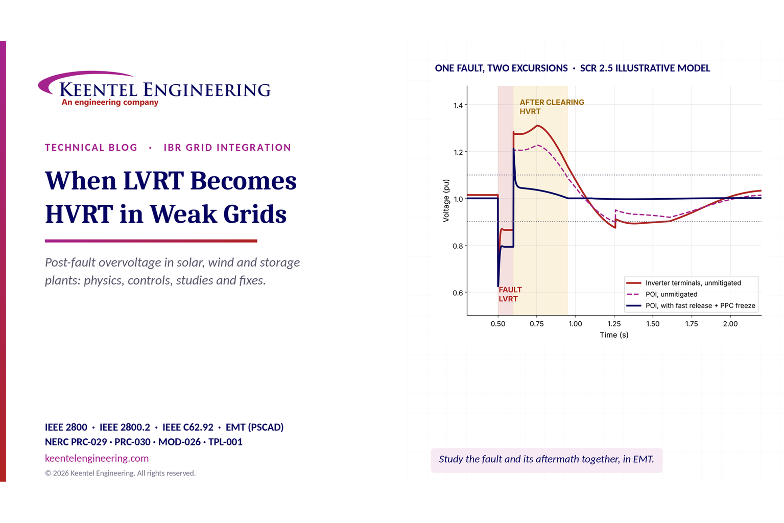
LVRT to HVRT transition in weak grids showing post-fault overvoltage and inverter voltage response.
By SANDIP R PATEL • November 14, 2026
Learn why LVRT becomes HVRT in weak grids, how post-fault overvoltage trips solar, wind and BESS plants, and how Keentel Engineering uses EMT studies.
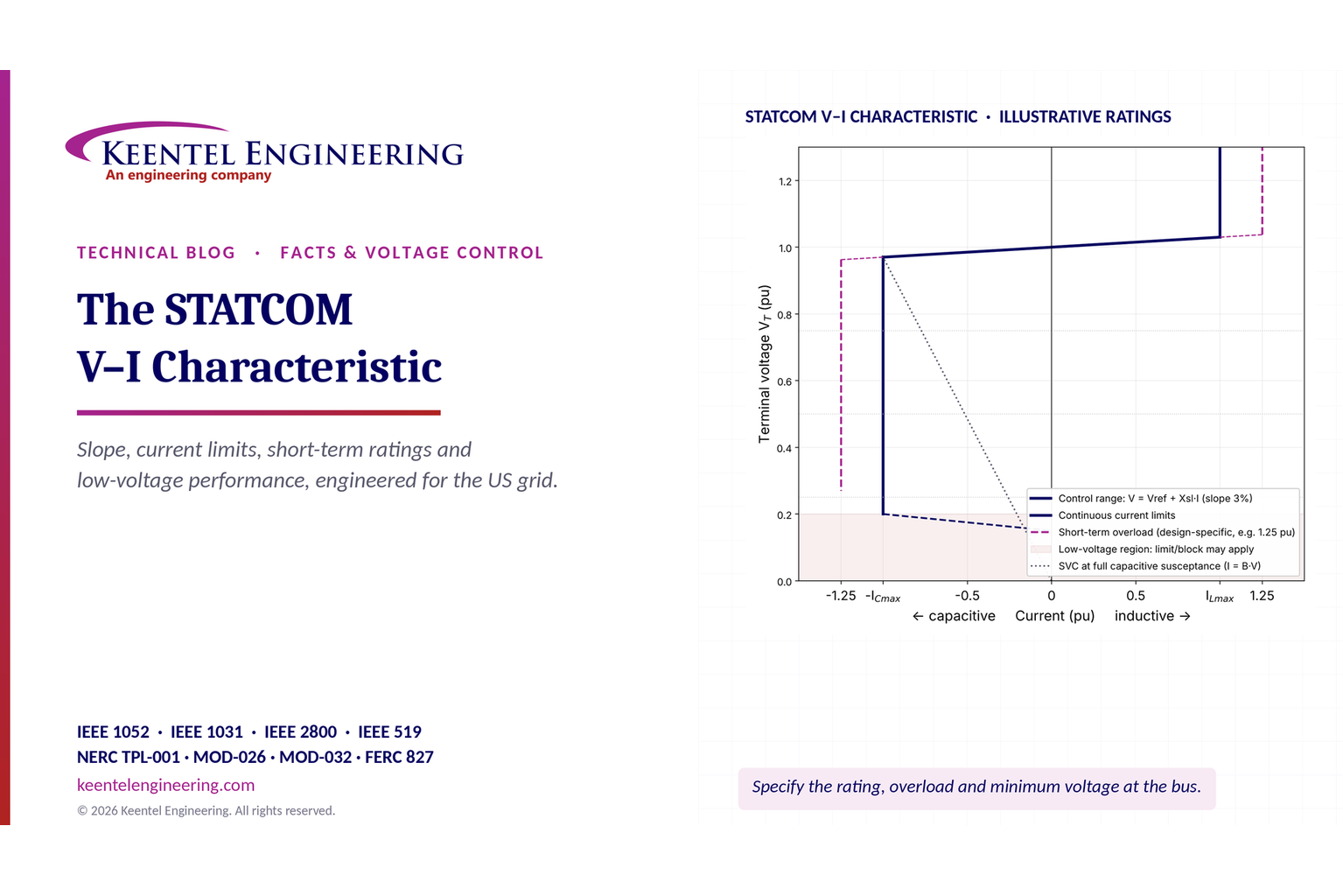
STATCOM V-I characteristic graph showing voltage regulation, current limits and short-term overload.
By SANDIP R PATEL • November 14, 2026
Explore STATCOM V-I characteristics, voltage control slope, current limits, short-term overload ratings, reactive power and low-voltage grid performance.
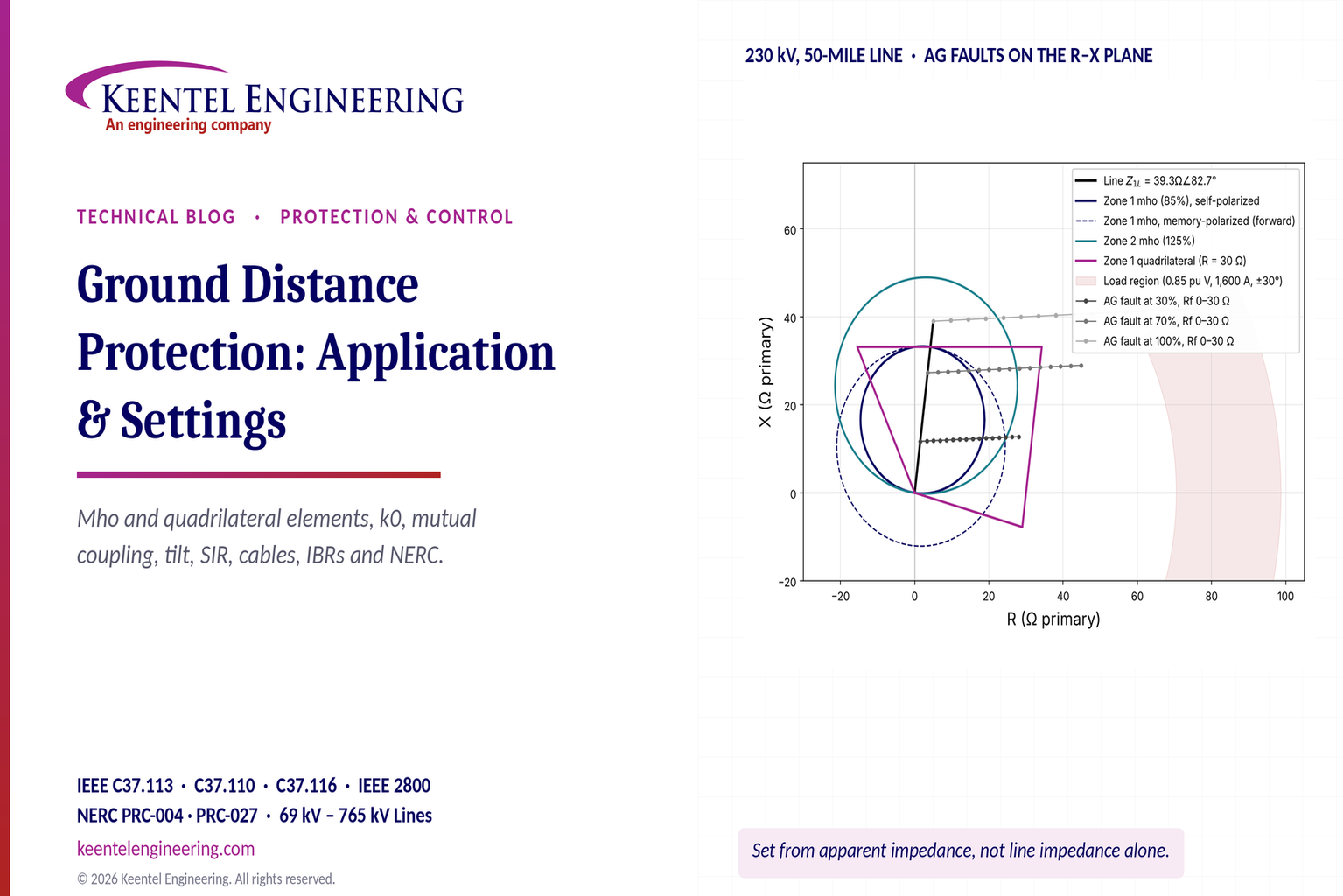
Ground distance protection R-X diagram showing mho and quadrilateral relay settings for a 230 kV lin
By SANDIP R PATEL • November 12, 2026
Learn ground distance protection settings for transmission lines: k0 compensation, mho and quadrilateral relays, mutual coupling and NERC compliance.
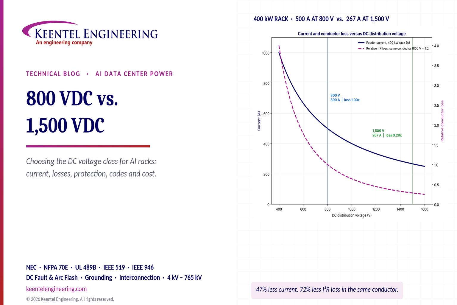
800 VDC vs. 1,500 VDC AI data center power distribution chart comparing rack current and conductor l
By SANDIP R PATEL • November 12, 2026
Compare 800 VDC vs. 1500 VDC for AI data centers. Explore efficiency, copper savings, DC protection, safety and power distribution with Keentel Engineering.
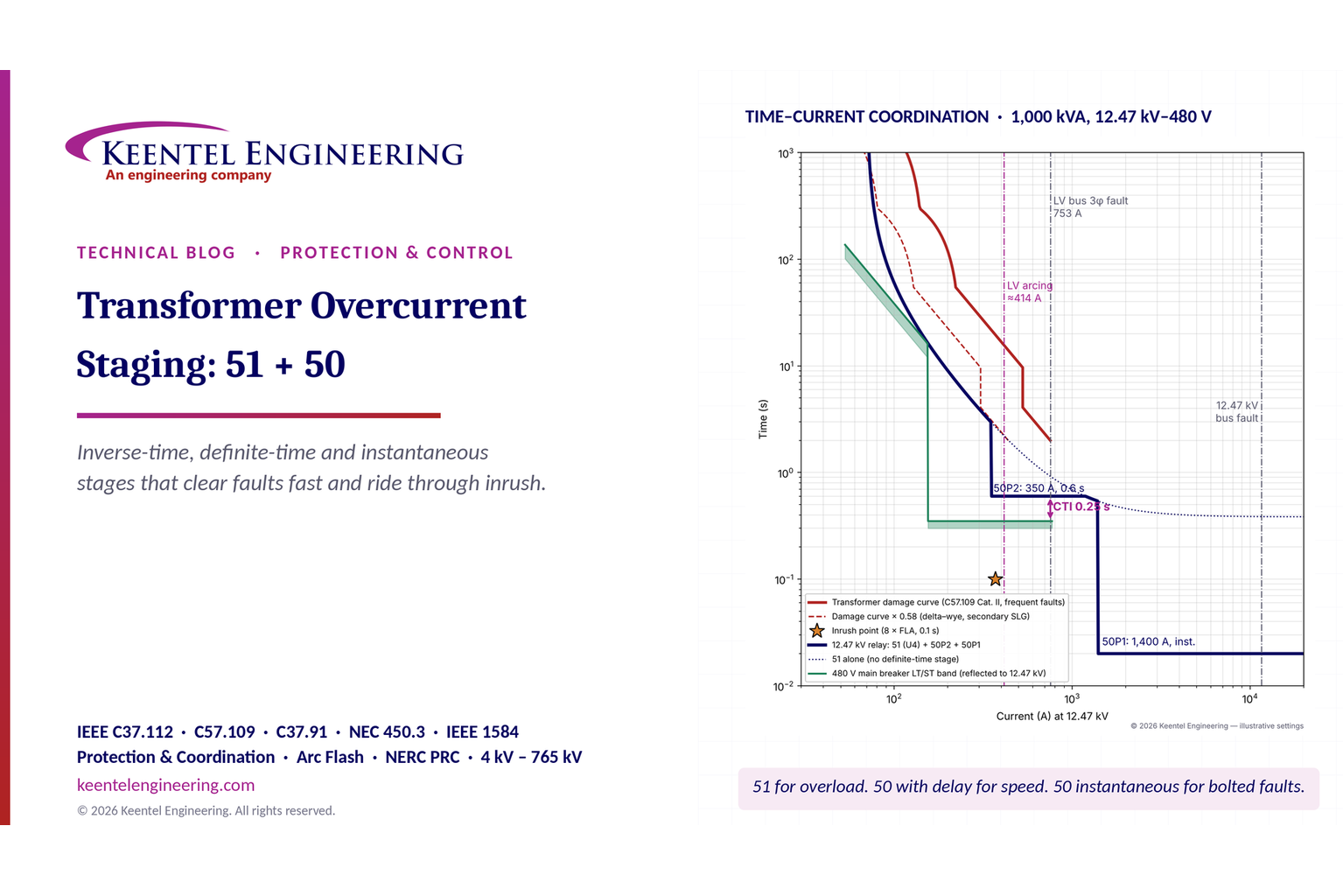
Transformer overcurrent protection 51/50 time-current coordination curves showing relay settings and
By SANDIP R PATEL • November 12, 2026
Learn transformer overcurrent protection using 50/51 relay stages, inverse-time curves, inrush checks, fault coordination and arc-flash mitigation.
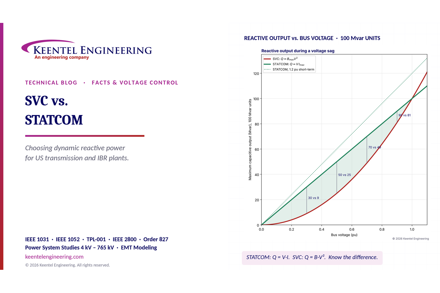
SVC vs. STATCOM reactive power comparison showing voltage stability and performance during voltage s
By SANDIP R PATEL • November 12, 2026
Compare SVC vs. STATCOM for dynamic reactive power compensation, voltage stability, weak grids, response time, harmonics and transmission system design.
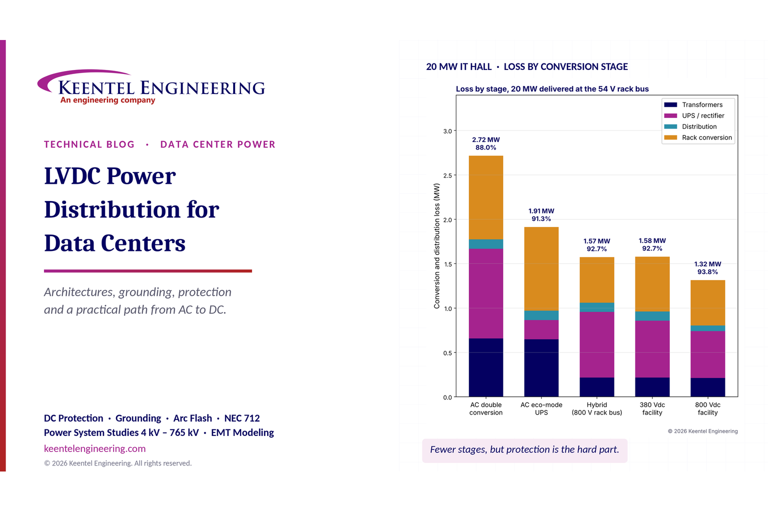
LVDC data center power distribution chart comparing AC, hybrid, 380 VDC and 800 VDC efficiency.
By SANDIP R PATEL • November 11, 2026
Explore LVDC power distribution for data centers, including 380V vs 800V DC, architecture, grounding, protection, UPS, energy efficiency and safety standards.
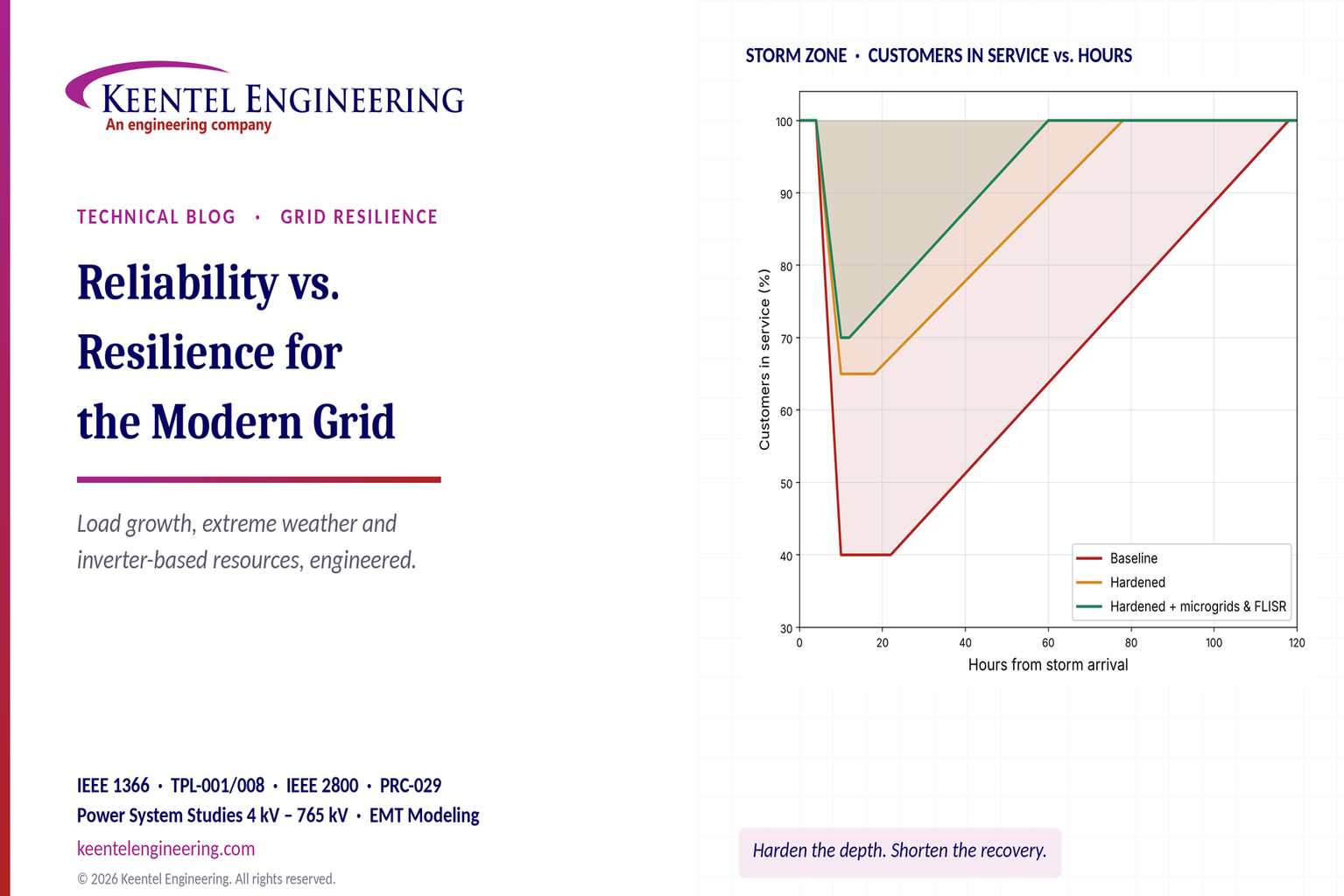
Grid reliability vs. resilience comparison showing storm outage and power restoration performance
By SANDIP R PATEL • November 11, 2026
Explore grid reliability vs. resilience, extreme weather planning, outage recovery, IEEE 1366 metrics, microgrids and IBR challenges with Keentel Engineering.