A Coordinated Electric System Interconnection Review—the utility’s deep-dive on technical and cost impacts of your project.

Challenge: Frequent false tripping using conventional electromechanical relays
Solution: SEL-487E integration with multi-terminal differential protection and dynamic inrush restraint
Result: 90% reduction in false trips, saving over $250,000 in downtime

The three operating regions you have to design to

Device Output vs voltage Response Best suited to Main limitations
Mechanically switched capacitor or reactor Proportional to voltage squared Seconds; discrete steps; limited switching operations per day Steady-state reactive supply, voltage profile, loss reduction No dynamic capability; step voltage change on switching; capability collapses when most needed
Static var compensator Capacitive branches proportional to voltage squared A few cycles; continuously controllable Continuous control where cost matters and deep voltage support is not the driver Square-law capability loss; harmonic filters are part of the plant and interact with the network
STATCOM Approximately proportional to voltage — constant current capability One to two cycles closed loop; converter response faster still Voltage stability margin, weak interconnections, fast disturbance recovery, flicker and unbalance compensation Higher capital cost; converter losses; adds a converter and its control dynamics to the network
Synchronous condenser Governed by machine capability and excitation Excitation response in the hundreds of milliseconds; inherent inertial response instantaneous System strength and inertia, short-circuit contribution, black start support Rotating plant with maintenance and losses; slower controlled response than a converter
STATCOM with energy storage Reactive as a STATCOM, plus real power within the storage rating As STATCOM for reactive; real power limited by storage Where a real power deficiency is part of the problem Cost and complexity of the storage; different failure and maintenance profile
Service area What we do for SST campuses Typical deliverables
Grid interconnection Site screening, large-load applications, independent studies, utility and RTO coordination in ERCOT, NYISO, PJM and other markets Screening reports, application data packages, load flow, contingency and stability studies, study review memos
EMT modeling Model requirements, vendor model review, campus aggregation, ride-through, weak-grid, control interaction and load-oscillation studies EMT model specifications, model acceptance reports, PSCAD study reports, SCR screening
MV/MVDC system studies AC and DC short-circuit, DC protection philosophy, AC protection, arc flash, grounding, insulation coordination Study reports, protection philosophy documents, settings files, arc flash labels, interface control documents
Power quality Emission requirements, frequency scans, IEEE 519-2022 compliance, filter sizing, flicker assessment Harmonic study reports, filter specifications, monitoring plans
Substation and transmission design HV/EHV substations, MV collectors, transmission lines, utility interface protection Physical and electrical drawing packages, specifications, bills of material, protection and control design
NERC compliance Registration and applicability, ride-through requirements, model validation, monitoring, compliance programs Applicability assessments, compliance programs, evidence packages, model validation reports
Owner's engineer and QA/QC SST, storage and substation specifications, design reviews, FAT and SAT plans and witnessing, multi-unit QA Specifications, review comments, test plans, witness reports, due diligence reports
Onsite generation and BESS Role definition and sizing, DC bus control architecture, fire and code compliance coordination, performance testing Sizing studies, control architecture documents, specifications, test procedures

Storage and generation

Term Meaning
AFE Active front end. The actively switched AC/DC stage of an SST that connects to the MV grid and sets its grid behavior.
Aggregated model A model in which many converters are represented by a smaller number of equivalent converters to make campus-scale simulation practical.
Arc flash The release of energy from an electric arc fault, assessed as incident energy at a working distance to set PPE and safe work practices.
BESS Battery energy storage system.
Blocking Turning off all converter switches so the converter stops feeding current, used to limit DC faults.
Composite load model A positive-sequence load model that combines several load types, such as motors, electronics and static loads.
DAB Dual active bridge. An isolated DC/DC converter topology with active bridges on both sides of a high-frequency transformer.
DC-link The internal DC capacitor bank between converter stages.
EMT Electromagnetic transient simulation. Time-domain simulation with microsecond time steps, used to study fast converter and network behavior.
FAT Factory acceptance test.
Grid-forming A converter control mode that sets its own voltage and frequency reference rather than following the grid's, providing support to weak grids.
HIL Hardware-in-the-loop testing, in which a real controller is tested against a real-time simulation.
IBR Inverter-based resource. Generation or storage connected to the grid through power electronics.
Insulation coordination Matching the insulation strength of equipment to the voltage stresses the system produces, with surge protection where needed.
ISC/IL The ratio of available short-circuit current to maximum demand load current at the point of common coupling, used to set IEEE 519 limits.
ISOP Input-series, output-parallel. A modular converter arrangement that shares a high input voltage across cells in series and combines their outputs in parallel.
Large load A load large enough to affect transmission system reliability. Definitions vary, for example 75 MW and above under Texas SB 6, or loads above 20 MW in the federal rulemaking proposal.
LVDC Low-voltage DC, such as 800 VDC or ±400 VDC rack distribution.
MFT Medium-frequency transformer. The compact isolation transformer inside an SST, operating at kilohertz frequencies.
MMC Modular multilevel converter. A converter built from many submodules with their own capacitors, producing a stepped multilevel waveform.
MVDC Medium-voltage DC distribution, roughly 1 kV to 35 kV DC in common usage.
OE Owner's engineer. An independent engineer representing the owner's technical interests.
PCC / POI Point of common coupling / point of interconnection, where the campus connects to the utility system and where compliance is usually assessed.
PLL Phase-locked loop. The control element that tracks grid voltage phase and frequency.
Positive-sequence model A fundamental-frequency, balanced dynamic model used in PSS®E, PSLF and similar tools.
Ride-through The ability to stay connected and keep operating during and after a grid disturbance within defined limits.
SAT Site acceptance test.
SCR Short-circuit ratio. Available short-circuit power divided by converter rating, a measure of grid strength.
SiC Silicon carbide, a wide-bandgap semiconductor material that allows higher voltage, higher frequency switching.
SST Solid-state transformer. A power electronic converter with a high-frequency isolation stage that replaces a 60 Hz transformer and rectifier chain.
Supraharmonics Emissions in the 2 kHz to 150 kHz range, above the range covered by most harmonic limits.
TDD Total demand distortion. Harmonic current distortion relative to maximum demand current, used in IEEE 519.
WSCR Weighted short-circuit ratio. An SCR screen that accounts for several inverter-based plants sharing a network area.

Links were current at publication (November 2026). Large-load rules, NERC actions and standards editions are changing quickly, so confirm current versions before relying on them.


Large-load reliability and NERC


Federal and state large-load rules


Solid-state transformers and DC data center power


Standards referenced (consult the publisher for the current edition)

Step 5 — options. Replacing or retrofitting the drives with active-front-end or 18-pulse units at about 5% THDi gives a TDD of about 1.5%. An active harmonic filter sized for the 5th and 7th could achieve a similar result at the facility level. A passive 5th-harmonic tuned filter would also work but must be checked for resonance with the utility system and with any future capacitors.


What this means for you.


The same drives can be compliant on a strong system and non-compliant on a weak one. Ask your utility for the maximum short-circuit current at the PCC early in design. If the ratio is below 50, plan for low-harmonic drives or filtering from the start; it is much cheaper than retrofitting.


9. Inverter-based resources: solar, storage and wind


Solar PV, battery energy storage and full-converter wind turbines use pulse-width-modulated inverters with output filters. They are generally low-distortion sources. IEEE Std 1547-2018 (distribution-connected resources) and IEEE Std 2800-2022 (transmission-connected resources) limit their current distortion — total rated-current distortion (TRD) of 5% with individual limits by order, measured against rated current rather than present output. In practice, quality inverters measure 1–3% at rated output.


Three cautions apply:


  1. Percentages rise at low output. At 10% of rated output a 2% distortion (of rated current) looks like 20% THD. Limits referenced to rated current, like TDD, avoid this trap.
  2. Inverters change the system's impedance. Plant collector cables, inverter output filters and capacitor banks add capacitance. They can create resonances near the 5th to 13th harmonics on the 34.5 kV collector or at a 138 kV, 230 kV or 345 kV point of interconnection, amplifying background distortion that the plant did not create.
  3. Background distortion matters. Inverters can absorb or amplify existing voltage distortion depending on their control design. Utilities increasingly require harmonic impedance studies for new plants, sometimes using electromagnetic transient (EMT) simulation.


Keentel's articles on harmonic resonance and on
weak-grid inverter stability cover these interactions in depth.


10. Data centers and other electronic facilities


Data centers are a special case because almost all their load is electronic. Points to check:


  • UPS rectifiers. Double-conversion UPS units with IGBT rectifiers typically draw less than 5% THDi at rated load, rising at low load. Older six-pulse or 12-pulse thyristor UPS rectifiers may need input filters.
  • Server and network power supplies. Modern units with active power factor correction have low 3rd harmonic. Legacy equipment does not. Measure a representative panel rather than assuming.
  • 208Y/120 V and 415Y/240 V distribution. Check neutral current and transformer K-factor as in Sections 4 and 7.
  • Generator operation. Test UPS and generator compatibility at the actual load level. Generator THDv can be three to four times the utility THDv for the same load.
  • Cooling plant. Chiller, pump, fan and cooling distribution unit drives often contribute more low-order harmonics than the IT load. Specify low-harmonic drives where the facility is large relative to the utility source.
  • Large-load interconnection. Utilities and grid operators now treat large data centers as high-impact loads. Harmonic studies and power quality monitoring are increasingly part of interconnection requirements, alongside ride-through and dynamic studies.


11. How a harmonic study is done


A harmonic study answers four questions: How much harmonic current will the facility inject? What voltage distortion will it cause? Will any resonance amplify it? What is the cheapest reliable fix? Keentel's typical workflow:


  1. Gather data. Single-line diagram; utility short-circuit data (maximum and minimum) at the PCC; utility background distortion if known; transformer impedances; cable lengths; capacitor banks and filters; drive, UPS and inverter data sheets with harmonic spectra.
  2. Measure existing conditions. For existing facilities, install class-compliant power quality meters at the PCC and key buses for at least one week, capturing 10-minute and 3-second data up to the 50th harmonic.
  3. Build the model. Represent sources as harmonic current injections and the network as frequency-dependent impedances, including transformer phase shifts that can cancel 5th and 7th harmonics between delta-delta and delta-wye units.
  4. Run a frequency scan. Plot driving-point impedance versus frequency at each important bus to find resonances, for all credible system configurations (tie breakers open/closed, capacitor steps in/out, generator versus utility).
  5. Run harmonic load flow. Calculate harmonic currents and voltages and compare them with IEEE 519 at the PCC and with equipment limits (IEEE 18 for capacitors, C57.110 for transformers) inside the facility.
  6. Design mitigation. Compare options for performance, cost, losses, footprint and future flexibility.
  7. Verify. Measure again after installation and document compliance with the statistical criteria.


12. Fixing harmonics: options compared
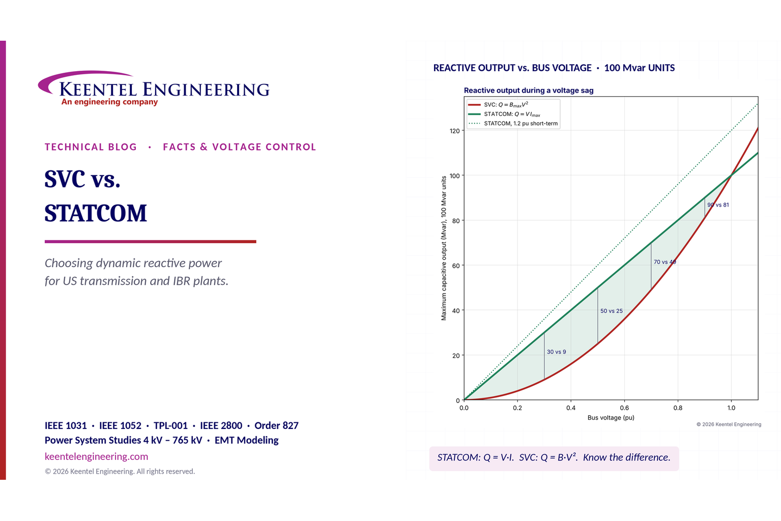
SVC vs. STATCOM: A US Engineering Guide to Selecting Dynamic Reactive Power Compensation

SVC vs. STATCOM reactive power comparison showing voltage stability and performance during voltage sags.
Calendar icon. D

November 12, 2026 | Blog

Part A — SVC vs. STATCOM at a Glance

When a US transmission planner, a renewable developer or a large-load customer needs fast, continuously controllable reactive power, the shortlist almost always starts with two shunt FACTS devices: the static var compensator (SVC) and the static synchronous compensator (STATCOM). A third option, the synchronous condenser, belongs on the same list whenever system strength or inertia is part of the problem.

All three regulate voltage by injecting or absorbing reactive power at a bus. They differ in how they produce that reactive power. That difference decides how much support each delivers when the grid needs it most, during and just after a fault, when voltage is depressed. It also decides how fast each responds, how much harmonic filtering it needs, how much land it occupies, what it costs to own for 30 years, and how it behaves on a weak grid crowded with inverter-based resources (IBRs).

This guide is Keentel Engineering's head-to-head selection guide. It does not repeat the voltage-stability and motor-stall mechanics covered in our earlier STATCOM article. Instead it compares the two technologies on the questions that decide a procurement:

  • Topology: what is actually inside each device.
  • Physics: the exact equations behind their voltage–current behavior.
  • Response time: what "fast" really means.
  • Harmonics: what each injects and how it is filtered.
  • Ownership: losses, footprint and lifecycle cost.
  • Weak grids: how each behaves at low short-circuit strength.
  • US compliance: where each fits under NERC and IEEE.

In plain terms: an SVC is a bank of reactors and capacitors whose effective size is adjusted by thyristor switches, so its output depends on the square of voltage. A STATCOM is a power-electronic voltage source that pushes a controlled current, so its output depends only on voltage itself. Both regulate voltage well in normal operation; they separate sharply when voltage collapses.

The two technologies side by side

Attribute SVC STATCOM
Operating principle Variable shunt susceptance: thyristor-controlled reactor (TCR) plus thyristor-switched or fixed capacitors and filters Voltage-source converter (VSC) with IGBTs or similar devices and a DC capacitor, coupled through a reactor and transformer
Behaves like A controlled impedance A controlled current source
Maximum capacitive output vs. bus voltage Falls with V² Falls with V (current held at its limit)
Output at 0.5 pu voltage (100 Mvar unit) 25 Mvar 50 Mvar (60 Mvar with 1.2 pu short-term overload)
Device response Thyristor firing changes within half a cycle; closed-loop voltage response typically 2–5 cycles Inner current loop in milliseconds; closed-loop voltage response typically 1–2 cycles
Harmonics TCR generates 5th, 7th, 11th, 13th; filters required Modern modular multilevel converters (MMC) produce very low harmonics; filters often unnecessary
Footprint Larger: outdoor reactors, capacitor racks, filter banks Smaller: indoor converter hall plus transformer and coolers
Typical losses at rated output About 0.5–1% of rating (topology-dependent) About 0.8–1.2% for MMC designs
Indicative installed cost Lower per Mvar of dynamic range Higher per Mvar, gap narrowing
Maturity Decades of US transmission service Widely deployed; now the default for many new projects
System strength contribution None Limited to converter current; no inertia

Six findings from Keentel's analysis

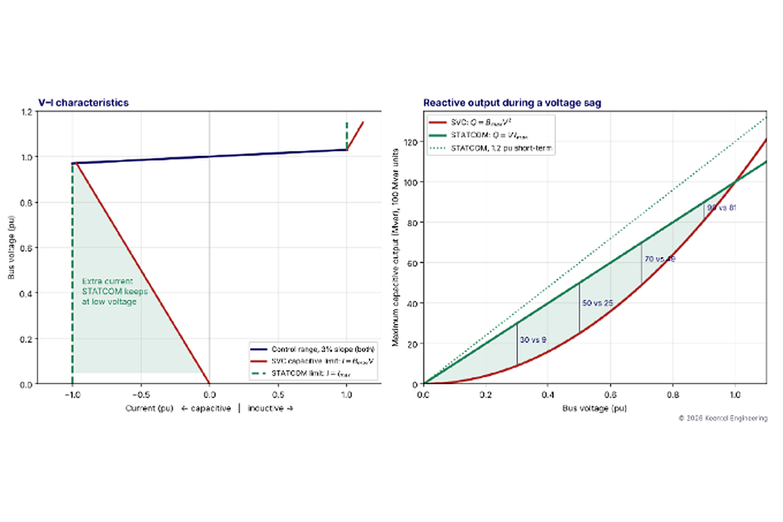
  • The V-versus-V² difference is real, but often overstated. A STATCOM does not "maintain full reactive power regardless of voltage." At its current limit its output falls in proportion to voltage: 50 Mvar at 0.5 pu for a 100 Mvar unit, against 25 Mvar for an SVC. The advantage is a factor of 1/V. That is decisive in deep sags and modest at 0.9 pu, where the numbers are 90 vs. 81 Mvar.
  • Response time is mostly about the control loop, not the semiconductor. Thyristors and IGBTs both switch in microseconds to milliseconds. The closed-loop voltage response that a planner actually sees is set by measurement filtering, regulator gain, slope and system strength. A well-tuned SVC can be fast enough; a poorly tuned STATCOM can be slow or unstable.
  • The SVC's harmonic filters are part of its design, not an add-on. A TCR's 5th harmonic peaks at about 5% of its rated current. The filters that absorb it also supply part of the capacitive range, so they must be engineered against the system's harmonic impedance from the outset
  • Lifecycle cost differences are smaller than capex differences. In our illustrative ±100 Mvar comparison, the STATCOM costs about 40% more up front. Over 30 years at 7%, it ends up about 34% higher in present-value terms, after lower losses and O&M are credited. Land, outage cost and schedule can close the rest of that gap at constrained sites.
  • On weak grids neither device adds system strength. Where short-circuit ratios fall toward 2 or below, the binding problem is often grid strength itself, which only synchronous condensers, grid-forming inverters or new transmission can supply.
  • The right answer is often a hybrid. Mechanically switched capacitors (MSC) or reactors (MSR) handle slow, steady-state needs, so a smaller fast device can be reserved for dynamic events. This applies to both SVC- and STATCOM-based solutions.

Figure 1. Left: idealized voltage–current characteristics with a 3% slope. In the control range both devices behave identically; below it, the SVC is bounded by its maximum susceptance while the STATCOM holds rated current. Right: maximum capacitive output of 100 Mvar units as bus voltage falls. The shaded area is the extra reactive support a STATCOM delivers during a sag.


Engineering review of common claims

Common claim Keentel's assessment
"SVC response is 1–3 cycles; STATCOM is milliseconds." Partly correct. Thyristor firing can change every half-cycle. The converter's inner current loop acts within a few milliseconds. But voltage-control response is closed-loop: typically 2–5 cycles (about 30–80 ms) for an SVC and 1–2 cycles for a STATCOM, and both depend on gain, slope and system strength.
"STATCOM maintains reactive current regardless of deep voltage drops." Correct for current, not for reactive power. Reactive current stays at rated (or short-term overload) value down to a low-voltage threshold, below which most controls block or limit. Reactive power still falls in proportion to voltage.
"SVC reactive output decreases with system voltage." Correct, and more precisely it falls with the square of voltage because an SVC at its limit is a fixed susceptance.
"STATCOM losses are higher." Older two-level and three-level PWM STATCOMs had losses of 1.5–2% or more. Modern MMC STATCOMs are about 0.8–1.2% at rated output and lower at partial output. An SVC with a large TCR circulating current against fixed capacitors can have significant standby losses. The comparison depends on topology and duty cycle.
"SVC can inject some low-order harmonics." Correct, and understated. An uncompensated TCR produces 5th and 7th harmonics of several percent of its rating. A delta connection cancels balanced triplens, and 12-pulse arrangements cancel the 5th and 7th. Filters remain mandatory.
"STATCOM is the gold standard for renewable-heavy weak grids." Often true for fast dynamic support and ride-through, but not universal. In very weak grids a current-source device that relies on a phase-locked loop (PLL) can itself contribute to control interactions. Synchronous condensers or grid-forming converters may be needed for strength.
"SVC for bulk transmission." SVCs remain cost-effective for large ratings, load compensation and sites with ample land, and many US SVCs are being life-extended or refurbished. New-build decisions increasingly favor STATCOMs or hybrids.

The illustrative system used in this guide


Keentel's worked examples use one consistent setting so the numbers can be compared directly.

Item Value
Point of connection 138 kV transmission substation, 60 Hz
Device rating ±100 Mvar at the 138 kV bus (both technologies)
Device medium-voltage bus 34.5 kV via a coupling transformer (illustrative)
Short-circuit strength studied 2,000 MVA (strong), 1,000 MVA (moderate), 500 MVA (weak)
Nearby IBR 300 MW of solar connected at 230 kV in Worked Example 6
Economic assumptions 30-year life, 7% discount rate, $50/MWh loss energy (illustrative)

Part B — SVC vs. STATCOM: An Engineering Selection Guide

1. Why dynamic reactive power matters


Voltage on a transmission system is held up by reactive power. Generators, shunt capacitors, line charging and FACTS devices supply it; loads, transformer and line reactance, and stalled motors consume it. In steady state, slow resources are enough: switched capacitor banks and reactors, transformer tap changers, and generator voltage schedules. During disturbances they are not. A fault depresses voltage across a wide area for a few cycles. After it clears, the system must re-establish voltage within a fraction of a second, or induction motors stall, inverter-based plants enter low-voltage modes and protection begins to operate.


Dynamic reactive devices fill that gap. They change output continuously and fast, holding a voltage set point through load swings and supporting recovery after faults. US planners need them for four recurring reasons:


  • Post-contingency voltage support to meet TPL-001-5.1 steady-state and transient voltage criteria, especially in load pockets and long radial paths.
  • Voltage stability margin where heavy transfers push a path near the nose of its PV curve.
  • Generator and IBR interconnection requirements, including the 0.95 power factor requirement of FERC Order No. 827 and dynamic reactive support under IEEE 2800-2022 as adopted by transmission owners.
  • Fluctuating loads: arc furnaces, large motors, rolling mills and, increasingly, AI data centers whose demand swings within seconds.


Mechanically switched capacitors (MSC) and reactors (MSR) are the cheapest reactive resource per Mvar, but they switch in discrete steps, take several cycles to close, need discharge time before reclosing and wear with each operation. SVCs and STATCOMs provide continuous, repeatable, fast control. The choice between them is the subject of the rest of this guide.


2. How an SVC works


2.1 Building blocks


An SVC is an assembly of shunt reactors and capacitors whose effective susceptance is controlled by thyristor valves. It connects to the transmission bus through a step-down coupling transformer, so the valves and passive components operate at a medium voltage. In the US that medium voltage is typically in the 13.8–34.5 kV class, and our examples use 34.5 kV. The main elements are:


  • Thyristor-controlled reactor (TCR): an air-core reactor in series with a pair of anti-parallel thyristors in each phase. Delaying the firing angle reduces the conduction period and therefore the effective inductive susceptance, continuously from full rating to zero.
  • Thyristor-switched capacitor (TSC): a capacitor bank in series with anti-parallel thyristors and a small damping reactor. A TSC is either fully on or fully off; it is never phase-controlled, because that would cause large inrush transients.
  • Fixed capacitors and harmonic filters: capacitor banks with series reactors tuned near the TCR's dominant harmonics (5th, 7th, sometimes 11th and 13th). They absorb TCR harmonics and supply part of the capacitive range.
  • Mechanically switched capacitors or reactors (MSC/MSR): breaker-switched banks on the medium-voltage or transmission bus, used for slow adjustments under the SVC controller's supervision.
  • Controls and protection: voltage measurement, a regulator with slope, firing logic, valve protection and coordination with external banks.


2.2 Common topologies

Topology Description Typical use
FC-TCR Fixed capacitors (filters) plus a TCR sized to cancel them and provide inductive range Simple, robust; relatively high standby losses because the TCR conducts heavily at zero net output
TSC-TCR One or more TSC steps plus a TCR sized to fill between steps Lower losses near zero output; most common modern transmission SVC
TSC only Discrete capacitive steps Low-cost capacitive-only support; output is stepwise
SVC with MSC/MSR Thyristor-controlled core plus mechanically switched banks Larger total range at lower cost; MSCs handle slow needs
12-pulse TCR Two TCRs fed from transformer windings phase-shifted by 30° Cancels 5th and 7th characteristic harmonics; smaller filters

New ParagraTCR branches are usually delta-connected. With balanced firing, triplen harmonic currents (3rd, 9th, 15th) circulate inside the delta and do not appear in the line currents. That is why the line-current spectrum is dominated by the 5th, 7th, 11th and 13th.


2.3 TCR susceptance as a function of firing angle


The firing angle convention matters, because textbooks use two. In this guide the firing angle α is measured from the zero crossing of the voltage across the TCR branch. Full conduction occurs at α = 90° (firing at the voltage peak), and the reactor is blocked at α = 180°. The conduction angle is σ = 2(π − α). With this convention, the fundamental-frequency susceptance of a TCR with inductance L is:

Equivalently, in terms of the conduction angle:

If a reference measures α from the voltage peak instead (0° = full conduction, 90° = blocked), substitute α' = α − 90°. Mixing the two conventions is a common source of specification and modeling errors, so a technical specification should state the convention explicitly.


Worked Example 1 — Sizing the TCR and TSC for a ±100 Mvar SVC at 138 kV

Requirement. The SVC must deliver +100 Mvar capacitive to −100 Mvar inductive at the 138 kV bus. For simplicity, ignore coupling-transformer reactive losses (in a real design they add several Mvar and shift the medium-voltage ratings).


Topology. A TSC-TCR design with fixed harmonic filters:


  • Fixed filters (5th and 7th tuned branches): 30 Mvar capacitive, always connected.
  • Two TSC steps of 35 Mvar each: 70 Mvar capacitive.
  • One delta-connected TCR.


Capacitive limit. Filters plus both TSCs, with the TCR blocked: 30 + 70 = 100 Mvar capacitive.

Inductive limit. Both TSCs off, the filters still connected, the TCR at full conduction. To achieve −100 Mvar net, the TCR must absorb 100 + 30 = 130 Mvar at rated voltage.


TCR branch reactance. Each delta branch carries one third of the rating at the 34.5 kV line voltage:

That corresponds to L = 72.9 mH per branch. The full-conduction line current is 130 MVA / (√3 × 34.5 kV) = 2,176 A.


Susceptance versus firing angle. Using the equation above:

Firing angle α (from voltage zero) B/Bmax TCR output (Mvar)
90° 1.000 130.0
100° 0.780 101.4
110° 0.573 74.5
120° 0.391 50.8
130° 0.242 31.5
140° 0.131 17.0
150° 0.058 7.5
160° 0.018 2.3
180° 0 0

The relationship is strongly nonlinear: half the TCR's range lies between 90° and about 120°. The SVC controller therefore linearizes it, computing the firing angle that produces the susceptance its voltage regulator demands.


Filling the gaps. With 35 Mvar TSC steps and a 130 Mvar TCR, every net output between −100 and +100 Mvar can be reached continuously. The controller selects the number of TSCs in service and sets the TCR to absorb the excess. Overlap between steps (TCR range larger than one TSC step) gives hysteresis, so the TSCs do not chatter.


2.4 TSC transient-free switching


A capacitor energized at an arbitrary point on the voltage wave draws a large inrush current. A TSC avoids this by firing its thyristors only when the voltage across the valve is near zero. That happens when the system voltage equals the voltage left on the capacitor, typically at a voltage peak when the capacitor is fully charged. Once blocked, the capacitor holds its peak charge, so it can be re-inserted within about one cycle without a transient. This is why TSC steps can switch much faster and more often than mechanically switched capacitors, which need several minutes of discharge time before reclosing.


2.5 SVC voltage–current characteristic


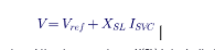
Within its control range an SVC is regulated to a slope, also called droop or current compensation:

Here I is positive for inductive current, and the slope reactance X(SL) is typically 1–5% on the SVC's rating base. Outside the control range the SVC is simply a fixed susceptance at its limit, so its current and reactive power are

3. How a STATCOM works


3.1 The voltage-source converter principle


A STATCOM is a voltage-source converter connected to the grid through a coupling reactance: a phase reactor, the leakage reactance of a coupling transformer, or both. The converter synthesizes a three-phase voltage Vc, nearly in phase with the system voltage V. The reactive power exchanged through the coupling reactance X is:

When Vc exceeds V, the STATCOM supplies reactive power (capacitive operation). When Vc is below V, it absorbs reactive power (inductive operation). A small phase shift lets the converter draw enough real power from the grid to cover its losses and hold its DC capacitor voltage. No large energy store is needed for reactive operation, because reactive power circulates between the phases.


In practice the converter is controlled as a current source. An inner current loop in a rotating dq reference frame, synchronized to the grid by a phase-locked loop (PLL), sets the reactive current in milliseconds. An outer voltage loop with slope sets the reactive current reference.


3.2 Converter topologies

Topology Characteristics Status
Two-level PWM VSC Simple; high switching frequency, so higher losses; output filters needed Common at distribution level and for small units
Three-level (NPC) VSC Lower harmonics and losses than two-level Used in medium ratings
Multi-pulse transformer-coupled (GTO era) Low switching frequency; complex magnetics Early transmission STATCOMs; largely superseded
Modular multilevel converter (MMC), cascaded H-bridge Many series submodules per phase, each switching slowly; nearly sinusoidal output; low losses, little or no filtering, often delta-connected Dominant for transmission-scale STATCOMs today

An MMC STATCOM in delta configuration with dozens of submodules per arm produces an output voltage staircase so fine that harmonic filters are often unnecessary. It is also modular: redundant submodules let it keep running after individual failures, which improves availability.


3.3 STATCOM voltage–current characteristic


In its control range a STATCOM uses the same slope characteristic as an SVC. Outside it, the converter is current-limited:

Two practical details matter in specifications:


  • Short-term overload. Many STATCOMs can deliver 1.2 pu or more current for a few seconds, limited by semiconductor junction temperature. This capability must be specified, tested and modeled; it is not automatic.
  • Low-voltage behavior. Below a threshold, often 0.2–0.3 pu, the converter may block or reduce current because the PLL cannot track a collapsed voltage reliably. A STATCOM's support therefore does not continue all the way to zero voltage.


3.4 DC capacitor sizing in brief


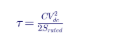
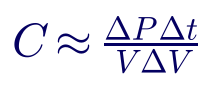
The DC capacitor must limit ripple and ride through transients, not store energy for reactive output. A useful first estimate relates stored energy to converter rating through a time constant:

Converters typically use τ of a few milliseconds to tens of milliseconds. In an MMC the energy is distributed across submodule capacitors, sized mainly for the voltage ripple each submodule sees. Adding substantial storage (a battery) turns the device into a STATCOM with energy storage, which can also exchange real power, for example for fast frequency response.


4. Reactive output when voltage collapses


Worked Example 2 — Support from 100 Mvar units at depressed voltage

At its capacitive limit, an SVC is a fixed capacitor: Q = B(max)V². A STATCOM at its current limit is a fixed current source: Q = V·I(max). For 100 Mvar units rated at 1.0 pu voltage:

Bus voltage (pu) SVC (Mvar) STATCOM (Mvar) STATCOM, 1.2 pu short-term (Mvar) STATCOM ÷ SVC
1.0 100 100 120 1.00
0.9 81 90 108 1.11
0.7 49 70 84 1.43
0.5 25 50 60 2.00
0.3 9 30 36 3.33
0.2 4 20 24 5.00

Interpretation. In the voltage range where most planning criteria live, 0.9–1.05 pu, the two devices are nearly equivalent: an SVC rated about 11% higher matches a STATCOM at 0.9 pu. The STATCOM's advantage grows sharply during deep sags, which is exactly when fault-induced delayed voltage recovery (FIDVR) and motor stalling begin. A planner who needs support at 0.7 pu would need an SVC rated about 143 Mvar to match a 100 Mvar STATCOM. That is the correct way to compare them: equal performance at the voltage that matters, not equal nameplate.


Two cautions keep the comparison honest:


  • The 0.2 pu row is theoretical for many STATCOMs. If the controls block below 0.3 pu, the STATCOM delivers nothing at 0.2 pu. Ask the supplier for the actual low-voltage characteristic and verify it in models.
  • Capacitive support is not the whole story. After fault clearing, voltage can overshoot, especially with capacitors and filters connected. An SVC's TCR and a STATCOM's inductive range must both absorb reactive power quickly to limit temporary overvoltage.


5. Response time: device versus closed loop


Specifications often quote response in a single number. It helps to separate three layers:

Layer SVC STATCOM
Switching device Thyristor firing adjustable once per half-cycle per valve (about 8.3 ms at 60 Hz) IGBT switching at hundreds of Hz to a few kHz; inner current loop acts within milliseconds
Measurement Voltage measurement and filtering, typically half a cycle to one cycle PLL and dq transformation, typically a few milliseconds; slower if tuned for weak grids
Closed-loop voltage response (to 90% of the final change) Typically 2–5 cycles (about 30–80 ms), depending on gain and system strength Typically 1–2 cycles (about 15–35 ms), depending on gain and system strength

The closed-loop response is set by the voltage regulator's gain, which must be tuned to the system's short-circuit strength. The plant seen by the regulator is approximately:

A regulator gain that gives a crisp response on a strong system becomes too aggressive when the system weakens after line outages: the effective loop gain rises as S(sc) falls. Both SVCs and STATCOMs therefore use gain supervision or adaptive gain, which reduces gain when oscillation is detected or when system strength is estimated to be low. A specification should require stable response across the full range of credible system strengths, not just a fast step at the strongest one.

For most transmission voltage-support needs, a 2–5 cycle response is fast enough. TPL-001 transient voltage criteria and FIDVR recovery play out over hundreds of milliseconds to seconds. Speed becomes decisive for flicker compensation, where the load changes within a cycle, and for some ride-through and power-oscillation-damping applications.


6. System strength and weak-grid behavior


Worked Example 3 — How much does 100 Mvar move the voltage?

Use ΔV ≈ ΔQ/S(sc) at the 138 kV bus, with the short-circuit ratio taken against a 300 MW plant at the same

Short-circuit MVA ΔV for 100 Mvar SCR for 300 MW Classification
2,000 5% 6.7 Strong
1,000 10% 3.3 Moderate
500 20% (linear estimate breaks down) 1.7 Weak

On a strong system the device nudges voltage; on a weak one it dominates it. Three consequences follow:


  • Gain scheduling is essential. A gain tuned for 2,000 MVA is four times too aggressive at 500 MVA.
  • Rating needs shrink but sensitivity grows. Fewer Mvar are needed to correct a given voltage deviation, but control interactions with nearby IBRs become likely.
  • The linear estimate fails. A 20% voltage change cannot be computed with small-signal formulas. Load-flow and EMT studies are needed.


6.1 Neither device makes the grid stronger


An SVC adds no fault current; at its limit it is just a susceptance. A STATCOM adds fault current only up to its converter rating, roughly 1.0–1.2 pu of its own current, and that current depends on a PLL tracking a severely distorted voltage. Neither provides inertia. For problems where the root cause is low system strength (IBR control instability, protection that cannot see faults, high voltage sensitivity), the candidate solutions are:


  • Synchronous condensers, which provide real short-circuit current (typically 4–6 times rating for a few cycles), rotating inertia and a voltage source behind reactance.
  • Grid-forming (GFM) converters, including GFM STATCOMs with energy storage, which behave as a voltage source and do not depend on a PLL in the same way.
  • Transmission reinforcement, which raises short-circuit strength directly.


6.2 Comparison with synchronous condensers

Attribute SVC STATCOM Synchronous condenser
Short-circuit contribution None About 1.0–1.2 pu of rating High, typically 4–6 pu of rating subtransient
Inertia None None (unless GFM with storage) Yes, flywheel can add more
Output at 0.5 pu voltage 25% 50% Rises transiently (field forcing)
Response 2–5 cycles 1–2 cycles Inherent subtransient response; AVR seconds
Losses Low–moderate Low–moderate Higher, about 1–2% plus auxiliaries
Maintenance Low Low Rotating machine: bearings, lube oil, outages
Footprint Large Smallest Large building, foundation
Typical role Voltage regulation, load compensation Voltage regulation, ride-through, flicker System strength, inertia, voltage support

The choice is not always either–or. Several US weak-grid regions are evaluating STATCOMs paired with synchronous condensers, or condensers alone, where IBR penetration has driven system strength down.


6.3 Control interactions


On weak grids, fast voltage controllers can interact with nearby IBR plant controllers, HVDC converters and each other. Common symptoms include sustained oscillations at a few hertz to tens of hertz, and voltage hunting between devices with similar time constants. Mitigations are:


  • Coordinate slope and gain with nearby plant controllers, and set deliberately different response speeds.
  • Run EMT studies with vendor-specific, user-defined models of every nearby converter, not only generic RMS models.
  • Check the SVC's capacitive banks for resonance with the network at low system strength, where the network impedance rises.


7. Harmonics and filtering


Worked Example 4 — TCR harmonics and a tuned filter

A delta TCR with balanced firing produces characteristic harmonics of order 6k ± 1 in the line current. The magnitude of each harmonic depends on the firing angle and peaks at an intermediate angle. As a percentage of the TCR's rated fundamental current:

Harmonic Maximum (% of rated fundamental) Firing angle at maximum
3rd (inside delta only) 13.8% 120°
5th 5.05% 108°
7th 2.59% 103°

For the 130 Mvar TCR in Worked Example 1, with a line current of 2,176 A at full conduction, the worst-case 5th harmonic is about 0.0505 × 2,176 ≈ 110 A at 34.5 kV.


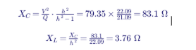
Filter design. Consider a 15 Mvar single-tuned 5th harmonic filter at 34.5 kV, tuned slightly below the harmonic at 4.7. The capacitor reactance for 15 Mvar effective output, accounting for the series reactor, is:

That gives C = 31.9 µF per phase (wye-equivalent) and L = 9.98 mH. The fundamental current is about 251 A, and the capacitor sees about 1.047 pu voltage because of the series reactor. The capacitor must be rated for that voltage plus the harmonic contribution, consistent with IEEE 18 and IEEE 1036 capacitor duties.


Why tune at 4.7, not 5.0? Tuning slightly low leaves margin for capacitor aging, temperature drift and frequency deviation. All of those shift the tuning upward. A filter tuned exactly at 5 could move above the 5th harmonic, where a parallel resonance with the system impedance sits right next to it.

Design checks. Every SVC filter design should check:


  • Background harmonics already on the system, which the filter will also absorb.
  • Parallel resonances between the filters and the network across the full range of system strengths and contingencies.
  • Capacitor, reactor and resistor duty including harmonics.
  • Compliance at the point of common coupling with IEEE 519-2022 voltage and current distortion limits.


STATCOMs. An MMC STATCOM typically produces harmonic voltages well within IEEE 519 limits without filters. A small high-pass filter may still be used, and two-level and three-level converters usually need filters for switching harmonics. The network's own background harmonics and resonance must still be studied, because the coupling transformer's capacitance and nearby capacitor banks can create resonances.


8. Losses, footprint and lifecycle cost


8.1 Losses


Losses depend strongly on topology and on how the device spends its time:


  • FC-TCR SVCs have high losses near zero output, because the TCR conducts heavily to cancel the fixed capacitors.
  • TSC-TCR SVCs keep losses low near zero output, because the TCR conducts lightly.
  • MMC STATCOMs have losses of roughly 0.8–1.2% at rated output and much less at light load. Older designs with higher switching frequencies were around 1.5–2% or more.
  • Auxiliaries (cooling, HVAC, controls) add tens to hundreds of kilowatts for any of these technologies.


The meaningful number is energy loss over the actual duty cycle. Most transmission devices sit near zero output most of the time, waiting for a disturbance, so standby losses dominate.


Worked Example 5 — 30-year lifecycle comparison

Illustrative assumptions for a ±100 Mvar device at 138 kV:

Item SVC (TSC-TCR) STATCOM (MMC)
Installed cost (illustrative) $30M $42M
Average losses over the duty cycle 350 kW 300 kW
Annual loss energy 3,066 MWh 2,628 MWh
Annual loss cost at $50/MWh $153k $131k
Annual O&M 1.0% of capex = $300k 0.8% of capex = $336k
Present value factor (7%, 30 years) 12.409 12.409
Net present cost $35.63M $47.80M

The present value factor is:

Net present cost is capex plus PVF times annual costs: for the SVC, 30 + 12.409 × 0.453 = $35.63M; for the STATCOM, 42 + 12.409 × 0.467 = $47.80M. The STATCOM is about 34% higher.


What this example leaves out:


  • Land and site work. A STATCOM's footprint is often 40–60% of an equivalent SVC's. At urban or constrained sites, land can swing the decision.
  • Rating at depressed voltage. If the requirement is defined at 0.7 pu, the SVC must be rated about 143 Mvar to match. That raises its cost by tens of percent and nearly closes the gap.
  • Outage and schedule costs. Shorter construction and modular redundancy can be worth more than loss savings.
  • Refurbishment. Thyristor valves and controls may need replacement after 20–25 years. Converters may need submodule and control replacement on a similar or shorter cycle. Spare parts and obsolescence plans belong in the specification.


All costs here are illustrative. Real quotations vary with market conditions, scope and site; use them only for structure, not budgets.


8.2 Footprint

Element SVC STATCOM
Coupling transformer Yes Yes (or direct connection at MV)
Valve or converter hall Thyristor valve building, compact Larger converter hall (MMC submodules)
Outdoor reactors TCR reactors, filter reactors Phase reactors (smaller)
Capacitor banks TSC and filter capacitors, often large racks Few or none
Cooling Water-glycol with outdoor coolers Water-glycol with outdoor coolers
Relative footprint 1.0 About 0.4–0.6

9. Hybrid solutions


Many of the best US projects use a fast device for dynamic needs and cheaper switched banks for steady-state needs:


  • STATCOM plus MSCs/MSRs: a ±50 Mvar STATCOM with 2 × 50 Mvar MSCs gives −50 to +150 Mvar of total range. The STATCOM's full dynamic range is kept available for disturbances, and the MSCs switch in slowly as steady-state conditions change.
  • SVC core with MSCs: the same principle with thyristor-based control.
  • Hybrid STATCOM with TSCs: a STATCOM with thyristor-switched capacitors, extending capacitive range at lower cost than converter capacity.
  • STATCOM with energy storage: adds real-power capability for frequency response or oscillation damping. This blurs into battery energy storage systems (BESS) with grid-support functions.


A coordinated controller is essential. It should keep the fast device near the center of its range in steady state ("reactive reserve management") by switching the slow banks, so full dynamic range is available when a fault occurs.


10. Where each device fits in US practice


10.1 Transmission voltage support under TPL-001


Planners use dynamic reactive devices to meet TPL-001-5.1 steady-state and transient voltage criteria after contingencies, and to avoid FIDVR in load pockets. Selection hinges on the voltage at which support is needed. If post-contingency voltages fall below about 0.8 pu during recovery, the STATCOM's V-versus-V² advantage typically wins on equal performance. If the need is mainly steady-state voltage control near 0.95 pu, an SVC or a hybrid with MSCs can be the lowest-cost solution.


10.2 IBR plants: Order 827 and IEEE 2800


FERC Order No. 827 requires newly interconnecting non-synchronous generators to provide dynamic reactive power within 0.95 leading to 0.95 lagging power factor at the high side of the generator substation. IEEE 2800-2022, adopted to varying degrees by US transmission owners and regions, sets reactive capability and ride-through performance at the point of measurement. Most plants meet these with inverter capability, but shortfalls are common in long collector systems.


Worked Example 6 — Reactive shortfall at a 300 MW solar plant

A 300 MW solar plant connects at 230 kV. At 0.95 power factor, the reactive requirement at the high side is:

Losses in the collector system and the main power transformer add about 30 Mvar, so the inverters must provide about 128.6 Mvar when the plant is at full output. With 320 MVA of inverter capacity:

The shortfall is 128.6 − 111.4 = 17.2 Mvar. The two common remedies are:


  • Oversize the inverters to about √(300² + 128.6²) ≈ 326.4 MVA, which also adds capability at all output levels.
  • Add a ±20 Mvar STATCOM at the collector bus, which also helps with ride-through and voltage regulation.


An SVC is rarely chosen for this role, because its output falls with V² during ride-through, its filters complicate the plant's harmonic study, and its footprint is larger. Always confirm the transmission owner's specific requirements, including whether reactive capability must be available at zero active power output.


10.3 Arc furnaces and flicker


Electric arc furnaces cause rapid, erratic reactive power swings that create voltage flicker. IEEE 1453 sets flicker assessment methods and planning levels. Historically, large SVCs with fast TCRs were the standard solution. STATCOMs now offer better flicker reduction factors because of their faster response, especially at higher frequencies within the flicker range. Selection rests on the required flicker reduction, the furnace size relative to system strength, and budget.


10.4 Large loads and data centers


Large AI data centers can change demand by hundreds of megawatts within seconds, and their power electronic loads can trip offline during voltage dips. Both effects stress local voltage. In load pockets at 138 kV and 230 kV, utilities are studying dynamic reactive devices at or near large-load interconnections. A STATCOM's fast response and low-voltage performance are attractive here, but the real issue may be large-load ride-through behavior, which is a load-side engineering problem.


10.5 HVDC and series-compensated corridors


Line-commutated HVDC converters consume large amounts of reactive power and need strong AC voltage. SVCs and STATCOMs have both supported HVDC terminals. Near series-compensated lines, subsynchronous interactions must be screened for any new converter-based device.


11. Standards and compliance map

Topic Standard or guide Notes
SVC specification IEEE 1031, Guide for the Functional Specification of Transmission Static Var Compensators Functional requirements, testing, performance
STATCOM specification IEEE 1052, Guide for Specification of Transmission Static Synchronous Compensator (STATCOM) Systems Ratings, performance, testing
Thyristor valves IEEE 1031 references; IEC valve test standards are commonly cited in US specifications Valve testing
Harmonics IEEE 519-2022 Limits at point of common coupling
Flicker IEEE 1453 Arc furnace and fluctuating loads
Shunt capacitors IEEE 18, IEEE 1036 Capacitor ratings and application
Transformers IEEE C57.12 series Coupling transformer
Seismic IEEE 693 Substation equipment seismic qualification
Facility ratings NERC FAC-008 Ratings of the device and its interconnection
Model data and validation NERC MOD-032, MOD-033; MOD-026 and MOD-027 where applicable Check applicability with the planning coordinator
Planning NERC TPL-001-5.1 Contingency voltage criteria
Protection system maintenance NERC PRC-005 Protection systems for the BES
Ride-through NERC PRC-024; PRC-029 for IBRs Applicability to a standalone STATCOM must be confirmed
Cybersecurity NERC CIP-002 through CIP-014 Depends on BES impact categorization
IBR performance IEEE 2800-2022, IEEE 2800.2 Where a STATCOM is part of an IBR plant

Applicability caution. A standalone STATCOM owned by a transmission owner is generally not a generating resource, and NERC's IBR registration criteria and PRC-029 apply to IBR generating facilities. When a STATCOM is part of an IBR plant, it is usually included in the plant's performance obligations. Confirm applicability with the planning coordinator and regional entity for each project.


12. Modeling for planning and design studies


Studies at each stage use different models:


  • Load flow: an SVC as a voltage-controlled shunt with susceptance limits; a STATCOM as a voltage-controlled source with current limits. Many programs have dedicated SVC and FACTS device records.
  • Positive-sequence stability (RMS): generic library models for SVCs and STATCOMs are available in the major US planning programs, for example the SVSMO family and the CSTCNT-type STATCOM model. Model names and features vary by program and version, so confirm the accepted models with the planning coordinator. For MOD-032 submissions, use the approved model list in the region.
  • EMT: for weak grids, harmonic interactions, subsynchronous screening and control interactions, require the supplier's detailed EMT model with real control code, validated against factory tests.
  • Harmonic studies: frequency-domain studies of the filters and network resonance, with the device modeled as a harmonic source.


Model validation after commissioning, by comparing recorded responses to simulations, should be part of the contract.


13. Specification checklist


A good functional specification, following the structure of IEEE 1031 and IEEE 1052, defines:


  • Ratings: continuous capacitive and inductive Mvar at a defined voltage, and short-term overload capability (magnitude and duration).
  • Voltage range: continuous operating range, and performance at depressed voltage down to a stated level.
  • Response: closed-loop response time and overshoot for defined step tests, across a defined range of system strengths.
  • Control modes: voltage control with slope, reactive power control, power oscillation damping, coordination with MSCs/MSRs and reactive reserve management.
  • Harmonics: performance against IEEE 519 at the point of common coupling, including background harmonics and network impedance envelopes.
  • Losses: guaranteed losses at defined operating points, with loss evaluation in the bid comparison.
  • Availability and redundancy: target availability, redundant submodules or valve levels, spares.
  • Environmental: ambient temperature range, altitude, seismic qualification to IEEE 693, audible noise limits.
  • Models: RMS and EMT models validated against testing, with control code and documentation.
  • Cybersecurity: compliance with applicable CIP requirements and utility security standards.
  • Training, documentation, warranty and lifecycle support: including obsolescence management.


14. Commissioning tests

Stage Tests
Factory Valve and submodule tests; control system tests with real-time simulation (hardware-in-the-loop)
Site, subsystem Transformer, reactor, capacitor and filter tests; protection relay tests; cooling system tests
Energization Step-by-step energization; harmonic measurements with branches in service
Performance Voltage reference step tests; reactive power range tests; gain and slope verification; switching of MSCs/MSRs
Staged faults or recorded disturbances Where practical, verify the dynamic response against models
Model validation Compare recorded responses with RMS and EMT models and update the models as required
Heat run Extended operation at rated output to confirm cooling and losses

Commissioning records should be kept as the baseline for future PRC-005 maintenance, model updates and performance reviews.


15. Decision matrix

Requirement Favors SVC Favors STATCOM Consider instead or in addition
Large steady-state reactive range at low cost ✓ MSCs/MSRs
Support during deep voltage sags (below 0.8 pu) ✓ Synchronous condenser
Constrained site footprint ✓
Arc furnace flicker mitigation ✓ (traditional) ✓ (better performance)
IBR plant reactive shortfall ✓ Oversized inverters
Low system strength or inertia Synchronous condenser, GFM
Refurbishment of existing SVC site ✓ (life extension) ✓ (replacement) Hybrid
Lowest harmonic impact ✓
Lowest capex for a given nameplate ✓

The right answer comes from studies, not rules of thumb: load flow and voltage-stability studies to size the need, dynamic studies to test performance at depressed voltage, EMT studies on weak grids, harmonic studies for any device with filters, and a lifecycle cost comparison on an equal-performance basis.


Part C — Case Studies

The following case studies are composites based on typical US project conditions. Names, locations and identifying details are withheld, and numbers are rounded.


Case Study 1 — An aging 345 kV SVC: refurbish or replace?


Situation


A transmission owner in the Midwest operated a ±200 Mvar SVC at a 345 kV substation, in service for about 28 years. The thyristor valves and the analog-era control system were near the end of their supported life. Spare parts were scarce, and the SVC had two forced outages in three years. Meanwhile, the region's generation had shifted from coal plants to wind, and post-contingency studies now showed voltages dipping to about 0.75 pu during the first second after certain 345 kV faults.


Analysis


Keentel compared three options on an equal-performance basis:


  • Refurbish the SVC: new valves and digital controls, reusing reactors, capacitors and the transformer after condition assessment. Lowest cost, but the V² characteristic delivered only about 112 Mvar at 0.75 pu.
  • Replace with a ±200 Mvar STATCOM: about 150 Mvar at 0.75 pu, a smaller footprint and lower harmonics, but at the highest cost.
  • Hybrid: ±125 Mvar STATCOM plus 2 × 75 Mvar MSCs at 345 kV, reusing part of the existing yard. At 0.75 pu, the STATCOM delivered about 94 Mvar dynamically, with MSCs switching in within seconds for sustained needs.


Dynamic studies showed that the critical recovery period needed about 140 Mvar of fast support at depressed voltage. Refurbishment alone fell short. The hybrid met the requirement once the STATCOM's 1.2 pu short-term overload (about 112 Mvar at 0.75 pu) was combined with a fast MSC that was already in service before the contingency under reactive reserve management.


Engineered solution


The owner selected the hybrid. Keentel prepared the functional specification under IEEE 1052, including the low-voltage characteristic and overload ratings, coordinated control with the MSCs, and an EMT model requirement.


Outcome


The new installation met the transient voltage criteria with margin, freed about 40% of the yard and was cheaper than a full-size STATCOM by about a quarter. The old SVC's coupling transformer was retained as a spare for the system after testing.


Case Study 2 — A 230 kV solar plant short of reactive power


Situation


A 250 MW solar project in the Southwest, connecting at 230 kV, had a long collector system and a large main power transformer. During the facility study, the transmission owner identified a reactive capability shortfall at the high side at full output, and the IEEE 2800-based ride-through requirements also had to be met.


Analysis


Keentel's reactive capability study found a shortfall of about 14 Mvar at 0.95 lagging power factor, with collector and transformer losses accounting for most of it. Oversizing the inverters would have required renegotiating supply contracts late in the project. The site was in a moderately weak area, with an SCR near 3.


Engineered solution


A ±20 Mvar STATCOM at the 34.5 kV collector bus, coordinated with the power plant controller. The STATCOM handled fast dynamic response, while the plant controller dispatched the inverters for steady-state voltage control. EMT studies with vendor-specific inverter and STATCOM models confirmed stable operation at the minimum system strength.


Outcome


 The plant met its reactive capability and ride-through requirements without changing the inverter order. Commissioning tests matched the model responses closely, which simplified the plant's model validation submission.


Case Study 3 — Flicker at a 138 kV steel mill


Situation


A steel producer planned to add an electric arc furnace at a 138 kV service in the Southeast. Pre-project studies predicted short-term flicker severity well above the utility's planning levels under IEEE 1453 at the point of common coupling, which also served residential customers.


Analysis


Keentel modeled the furnace using measured data from a similar furnace and evaluated an SVC and a STATCOM. Both reduced flicker, but the SVC's predicted flicker reduction factor (about 2) was not enough to meet the planning level. The STATCOM's faster response achieved a factor of about 4. The SVC also required larger 2nd- and 3rd-harmonic filters to handle the unbalanced, interharmonic-rich furnace current.


Engineered solution


A STATCOM sized to the furnace's reactive swings, with a small fixed capacitor bank for power factor correction and filtering. The control was configured for fast load compensation with independent phase control.


Outcome


Measured flicker after commissioning was within planning levels, and harmonic distortion at the point of common coupling met IEEE 519. The mill's power factor improved enough to reduce demand charges, and the furnace's productivity rose because voltage at the electrodes was steadier.


Part D — 20-Question Technical FAQ

  • 1. What is the basic difference between an SVC and a STATCOM?

    An SVC is a variable impedance: thyristor-controlled reactors and switched capacitors whose effective susceptance is adjusted to regulate voltage. A STATCOM is a voltage-source converter that injects a controlled current. At its limit, an SVC's output falls with the square of voltage, while a STATCOM's falls only in proportion to voltage.

  • 2. Does a STATCOM deliver full reactive power at any voltage?

    No. It can hold rated reactive current down to a low-voltage threshold, but reactive power is voltage times current, so output falls linearly with voltage. Below roughly 0.2–0.3 pu, many STATCOM controls block or reduce current.

  • 3. How much more support does a STATCOM give during a voltage sag?

    By a factor of 1/V compared with an SVC of the same rating. At 0.9 pu the STATCOM gives about 11% more; at 0.7 pu, 43% more; at 0.5 pu, twice as much.

  • 4. Is a STATCOM always faster than an SVC?

    Its inner current control is faster, but the closed-loop voltage response depends on the regulator gain, measurement filtering and system strength. Typical closed-loop responses are 1–2 cycles for a STATCOM and 2–5 cycles for an SVC. Both are fast enough for most transmission voltage-support needs.

  • 5. Why does an SVC need harmonic filters?

    A TCR conducts in partial cycles, which produces harmonic currents. The 5th harmonic can reach about 5% of the TCR's rated current and the 7th about 2.6%. Filters absorb these harmonics and also supply part of the SVC's capacitive range.

  • 6. Do STATCOMs need harmonic filters?

    Modern modular multilevel STATCOMs usually do not, because their output is close to sinusoidal. Two-level and three-level designs often need filters. A harmonic and resonance study is still required for any installation.

  • 7. Which has lower losses?

    It depends on topology and duty cycle. A TSC-TCR SVC has low losses near zero output; a fixed-capacitor TCR SVC has high standby losses. Modern MMC STATCOMs run about 0.8–1.2% at rated output. Compare guaranteed losses at the operating points where the device actually spends its time.

  • 8. Which is cheaper?

    An SVC usually has lower capital cost per Mvar of nameplate. When the requirement is defined at depressed voltage, the SVC must be oversized to match, and land, schedule and lifecycle costs can narrow or reverse the gap.

  • 9. Which takes less space?

    A STATCOM, typically about 40–60% of the footprint of an equivalent SVC, because it needs few or no capacitor banks and filters.

  • 10. Can an SVC or STATCOM fix a weak grid?

    Not by itself. Neither adds meaningful short-circuit strength or inertia. They regulate voltage, but if low system strength is the root problem, consider synchronous condensers, grid-forming converters or transmission reinforcement.

  • 11. When should I choose a synchronous condenser instead?

    When you need short-circuit current for protection and IBR stability, inertia, or a strong voltage source, especially in areas with high IBR penetration. Condensers have higher losses and maintenance needs, so they are often paired with fast power-electronic devices.

  • 12. What is the slope setting and why does it matter?

    Slope (droop) makes the regulated voltage vary slightly with the device's current, typically 1–5% across the full range. It shares reactive power among devices, prevents the device from reaching its limits for small voltage deviations, and improves stability.

  • 13. What standards govern SVC and STATCOM specifications in the US?

    IEEE 1031 provides functional specification guidance for transmission SVCs, and IEEE 1052 does the same for transmission STATCOMs. IEEE 519 covers harmonics, IEEE 1453 flicker, IEEE 693 seismic qualification, and the IEEE C57.12 series covers the coupling transformer.

  • 14. Which NERC standards apply?

    Typically TPL-001 for planning, FAC-008 for facility ratings, MOD-032 and MOD-033 for model data and validation, PRC-005 for protection system maintenance, and CIP standards depending on impact categorization. Ride-through standards such as PRC-024 and PRC-029 apply to generating resources; confirm applicability for any standalone device with your planning coordinator.

  • 15. Can a STATCOM solve a solar or wind plant's reactive shortfall?

    Yes. It is a common solution when inverter capability, minus collector and transformer losses, falls short of the 0.95 power factor requirement of FERC Order No. 827 or the transmission owner's IEEE 2800-based requirements. Oversizing inverters is the main alternative.

  • 16. What models do I need for interconnection studies?

    Generic positive-sequence models from the approved list for planning studies, plus a detailed EMT model with the supplier's real control code for weak-grid, harmonic and interaction studies. Confirm model names and versions with the planning coordinator.

  • 17. Should I refurbish an old SVC or replace it?

    Compare both on an equal-performance basis. If the system now needs support at deep voltage sags, or space is needed, replacement or a STATCOM hybrid may win. If the needs remain steady-state and the passive equipment is sound, refurbishing the valves and controls can be the lowest-cost option.

  • 18. What is a hybrid compensator?

    A combination of a fast device (SVC or STATCOM) and cheaper mechanically switched capacitors or reactors. The slow banks handle steady-state needs, keeping the fast device's range available for disturbances.

  • 19. Can a STATCOM help with frequency?

    Not by itself, because it exchanges essentially no real power. Adding energy storage lets it provide fast frequency response, and grid-forming controls can add synthetic inertia within its energy limits.

  • 20. What tests should be done at commissioning?

    Subsystem tests, energization with harmonic measurements, voltage reference step tests, range and slope verification, coordination tests with switched banks, a heat run, and model validation against recorded responses. These records become the baseline for maintenance and future model updates.


How Keentel Engineering Helps

Keentel Engineering supports utilities, independent power producers, large-load developers and industrial customers through every stage of a dynamic reactive power project:


  • Needs assessment: load flow, PV/QV and dynamic studies to define how many Mvar are needed, where, how fast and at what voltage.
  • Technology selection: equal-performance comparison of SVC, STATCOM, hybrid and synchronous condenser options, with lifecycle cost analysis.
  • Weak-grid and EMT studies: system strength screening, control interaction studies and EMT modeling with vendor-specific models.
  • Harmonic and flicker studies: filter design review, resonance scans and compliance with IEEE 519 and IEEE 1453.
  • Specification and procurement: functional specifications based on IEEE 1031 and IEEE 1052, bid evaluation and loss evaluation.
  • Interconnection support: reactive capability studies for IBR plants under FERC Order No. 827 and IEEE 2800, and model submissions under MOD-032.
  • Substation design and protection: physical layout, grounding, protection and control design for the coupling transformer, filters and banks.
  • Commissioning and model validation: test planning, witness testing and model validation against recorded performance.


Why Clients Choose Keentel


  • Planning and design under one roof: the engineers who run the studies also write the specifications and review the designs.
  • US standards fluency: daily work with NERC, IEEE, FERC and regional requirements.
  • Independent advice: we are not tied to any equipment supplier, so recommendations follow the engineering.
  • Practical, documented results: clear reports, auditable calculations and models that pass review.


Talk to an Engineer


Planning a new reactive compensation project, refurbishing an existing SVC or closing an interconnection reactive shortfall? Keentel Engineering can help you choose the right technology and size it correctly.


  • Phone: (813) 389-7871
  • Email: contact@keentelengineering.com
  • Book a 15-minute call: calendly.com/keentel-engineering/15min


References


  • IEEE Std 1031, IEEE Guide for the Functional Specification of Transmission Static Var Compensators.
  • IEEE Std 1052, IEEE Guide for Specification of Transmission Static Synchronous Compensator (STATCOM) Systems.
  • IEEE Std 519-2022, IEEE Standard for Harmonic Control in Electric Power Systems.
  • IEEE Std 1453, IEEE Recommended Practice for the Analysis of Fluctuating Installations on Power Systems.
  • IEEE Std 18, IEEE Standard for Shunt Power Capacitors; IEEE Std 1036, IEEE Guide for the Application of Shunt Power Capacitors.
  • IEEE Std 693, IEEE Recommended Practice for Seismic Design of Substations.
  • IEEE Std 2800-2022, IEEE Standard for Interconnection and Interoperability of Inverter-Based Resources Interconnecting with Associated Transmission Electric Power Systems.
  • NERC Reliability Standards TPL-001-5.1, FAC-008, MOD-032, MOD-033, PRC-005, PRC-024, PRC-029 and CIP-002.
  • FERC Order No. 827, Reactive Power Requirements for Non-Synchronous Generation (2016).
  • N. G. Hingorani and L. Gyugyi, Understanding FACTS: Concepts and Technology of Flexible AC Transmission Systems, IEEE Press.
  • R. M. Mathur and R. K. Varma, Thyristor-Based FACTS Controllers for Electrical Transmission Systems, IEEE Press/Wiley.
  • Keentel Engineering, "STATCOM and Voltage Stability," companion technical blog.


Disclaimer


This article is for general technical information only. Worked examples use illustrative values and simplified assumptions; costs, losses and ratings are not quotations or design values. Standards are cited as of publication and may be revised; always confirm the current edition and its applicability with the relevant planning coordinator, transmission owner or regional entity. Project decisions require site-specific studies by qualified engineers.

© Keentel Engineering


Office Address Phone
Head Office — Tampa 400 N Ashley Dr STE #2600, Tampa FL 33602 (813) 389-7871
Austin 5900 Balcones Drive STE 100, Austin TX 78731 (512) 591-0752
Sacramento 1401 21st St Ste R, Sacramento CA 95811 (916) 913-4524
Baltimore 306 W Redwood St STE 200, Baltimore MD 21201 (410) 225-2181


A smiling man with glasses and a beard wearing a blue blazer stands in front of server racks in a data center.

About the Author:

Sandip "Sonny" R. Patel, P.E.

IEEE Senior Member · Founder & CEO, Keentel Engineering

In 1995, Sonny Patel earned his Electrical Engineering degree from the University of Illinois. But degrees don't build legacies — action does.

For three decades, he has worked the power industry from every side of the table: 16 years as a utility engineer at Exelon/Commonwealth Edison; generation leadership across hydroelectric, industrial steam turbine, and a 9 GW renewable fleet; NERC Regional Entity Senior Compliance Engineer and Audit Team Lead, auditing some of the nation's largest utilities; and testing and commissioning lead on equipment up to 765 kV — the very top of the North American grid.Utility. Generator. Regulator. Consultant. Few engineers have seen all four seats. Fewer still have sat in them.

His experience spans nuclear, hydro, conventional generation, renewables, oil and gas, mining — and today's data centers, where he is authoring a three-book series on data center design. He is a Licensed Professional Engineer in six states and a Licensed Electrical Contractor in Florida (Unlimited EC) — he doesn't just design the work; he's qualified to stand behind its execution.Today, as Founder and CEO of Keentel Engineering, Sonny leads a nationwide team of engineers delivering substation design, power system studies, NERC compliance, and commissioning — done right, coast to coast.Three decades. Every side of the table. One standard: accountable engineering.

Four workers in safety vests and helmets stand with arms crossed near wind turbines.

Let's Discuss Your Project

Let's book a call to discuss your electrical engineering project that we can help you with.

Man in a blazer and open shirt, looking at the camera, against a blurred background.

About the Author:

Sandip "Sonny" R. Patel, P.E.

IEEE Senior Member · Founder & CEO, Keentel Engineering

In 1995, Sonny Patel earned his Electrical Engineering degree from the University of Illinois. But degrees don't build legacies — action does.

For three decades, he has worked the power industry from every side of the table: 16 years as a utility engineer at Exelon/Commonwealth Edison; generation leadership across hydroelectric, industrial steam turbine, and a 9 GW renewable fleet; NERC Regional Entity Senior Compliance Engineer and Audit Team Lead, auditing some of the nation's largest utilities; and testing and commissioning lead on equipment up to 765 kV — the very top of the North American grid.

Utility. Generator. Regulator. Consultant. Few engineers have seen all four seats. Fewer still have sat in them.

His experience spans nuclear, hydro, conventional generation, renewables, oil and gas, mining — and today's data centers, where he is authoring a three-book series on data center design. He is a Licensed Professional Engineer in six states and a Licensed Electrical Contractor in Florida (Unlimited EC) — he doesn't just design the work; he's qualified to stand behind its execution.

Today, as Founder and CEO of Keentel Engineering, Sonny leads a nationwide team of engineers delivering substation design, power system studies, NERC compliance, and commissioning — done right, coast to coast.Three decades. Every side of the table. One standard: accountable engineering.

Leave a Comment

Related Posts

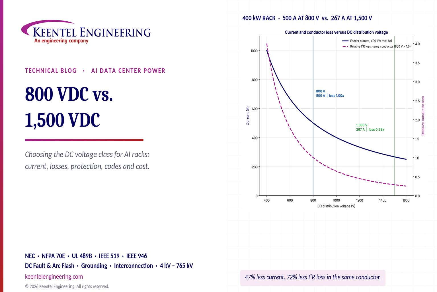
800 VDC vs. 1,500 VDC AI data center power distribution chart comparing rack current and conductor l
By SANDIP R PATEL • November 12, 2026
Compare 800 VDC vs. 1500 VDC for AI data centers. Explore efficiency, copper savings, DC protection, safety and power distribution with Keentel Engineering.
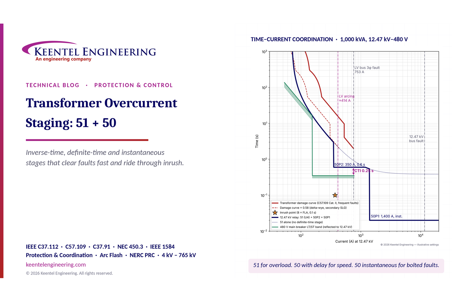
Transformer overcurrent protection 51/50 time-current coordination curves showing relay settings and
By SANDIP R PATEL • November 12, 2026
Learn transformer overcurrent protection using 50/51 relay stages, inverse-time curves, inrush checks, fault coordination and arc-flash mitigation.
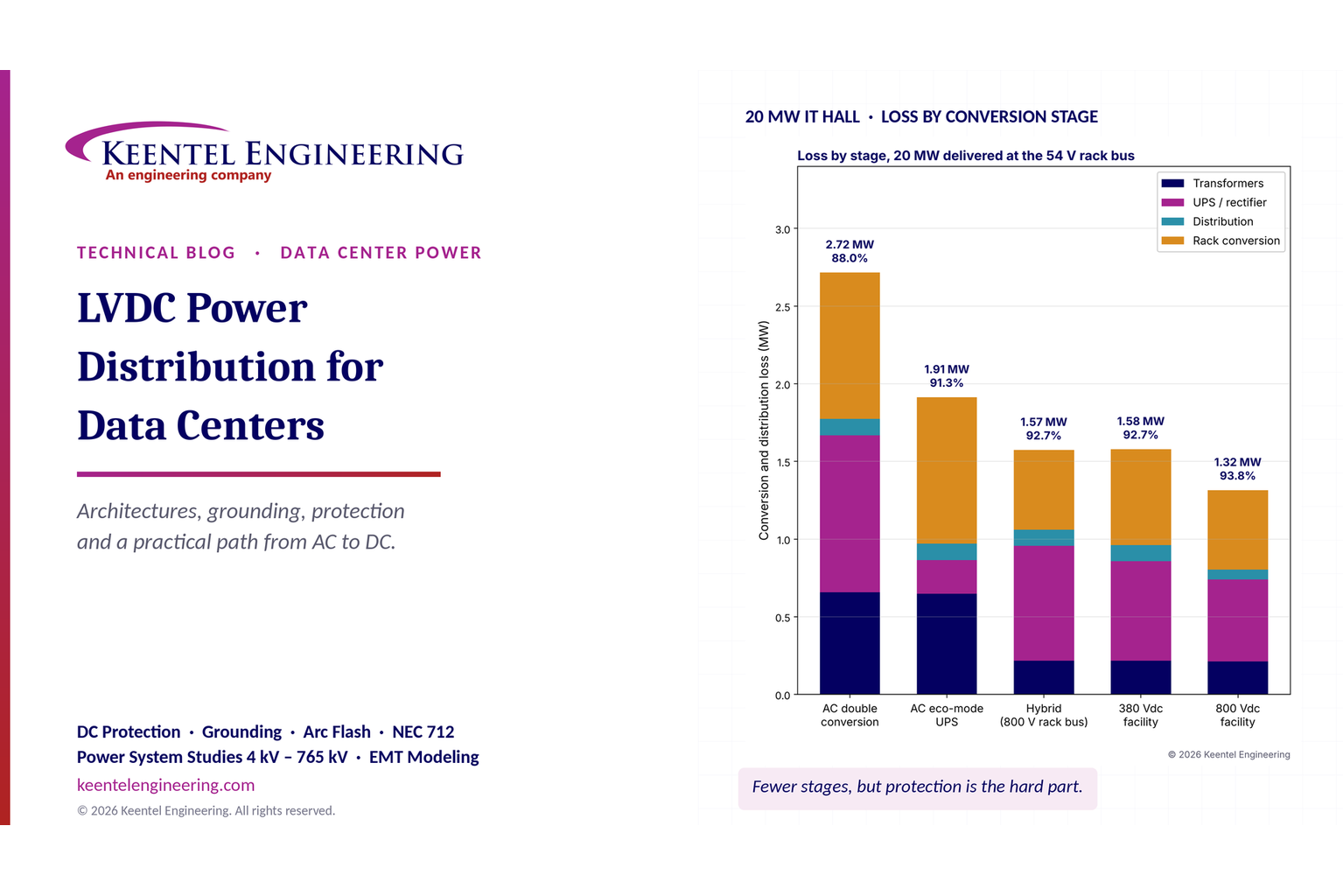
LVDC data center power distribution chart comparing AC, hybrid, 380 VDC and 800 VDC efficiency.
By SANDIP R PATEL • November 11, 2026
Explore LVDC power distribution for data centers, including 380V vs 800V DC, architecture, grounding, protection, UPS, energy efficiency and safety standards.
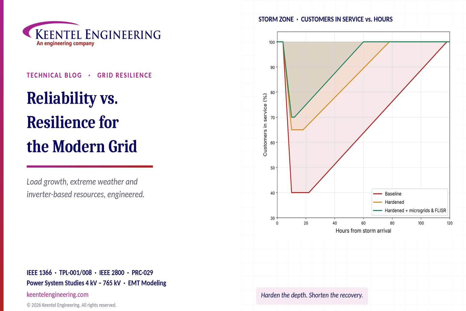
Grid reliability vs. resilience comparison showing storm outage and power restoration performance
By SANDIP R PATEL • November 11, 2026
Explore grid reliability vs. resilience, extreme weather planning, outage recovery, IEEE 1366 metrics, microgrids and IBR challenges with Keentel Engineering.
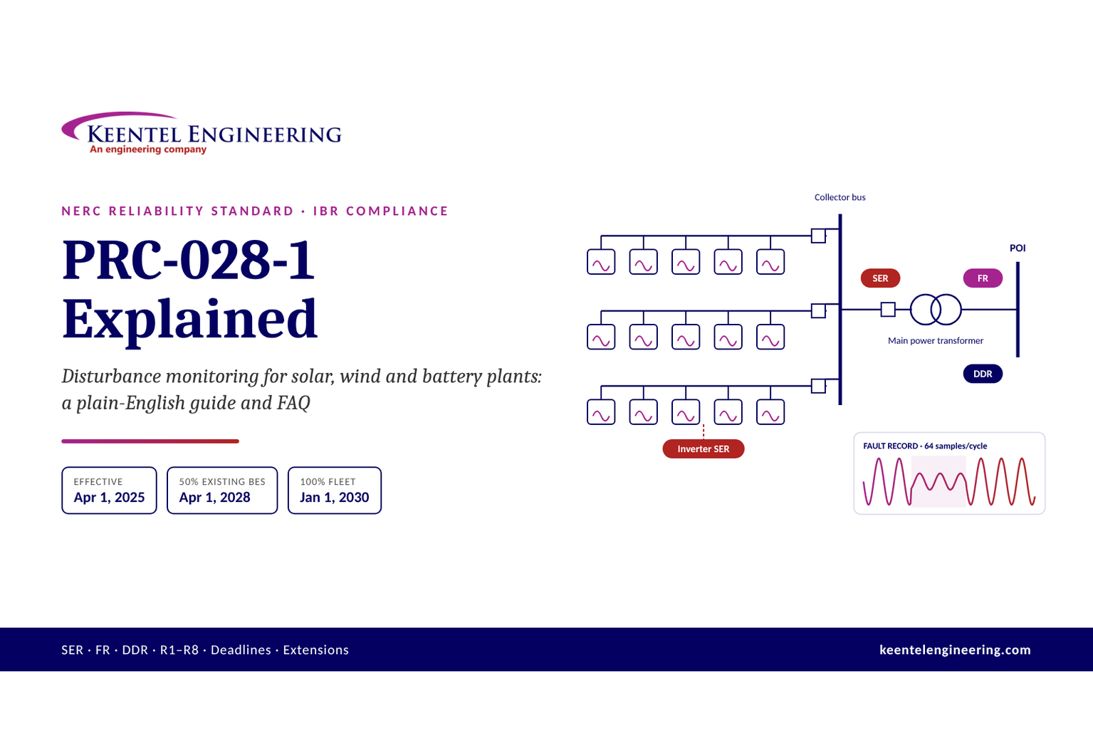
PRC-028-1 Explained: What Every Solar, Wind & Battery Owner Needs to Know
By SANDIP R PATEL • November 10, 2026
Learn NERC PRC-028-1 requirements for solar, wind and BESS, including disturbance monitoring, recording standards, deadlines and compliance steps from Keentel.
1 GW data center power capacity breakdown from utility service to GPU racks.
By SANDIP R PATEL • November 8, 2026
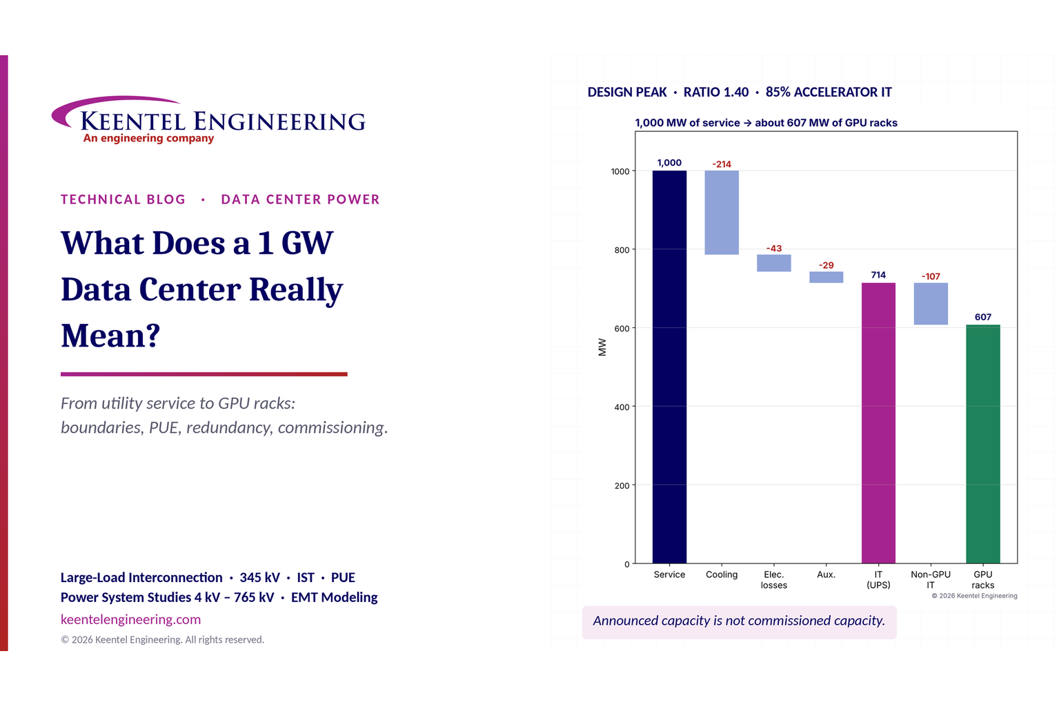
What does a 1 GW data center mean? Explore power capacity, PUE, GPU racks, grid interconnection and commissioning with Keentel Engineering's expert guide.
TPL-001-5.1 transmission planning performance and NERC compliance requirements
By SANDIP R PATEL • November 8, 2026
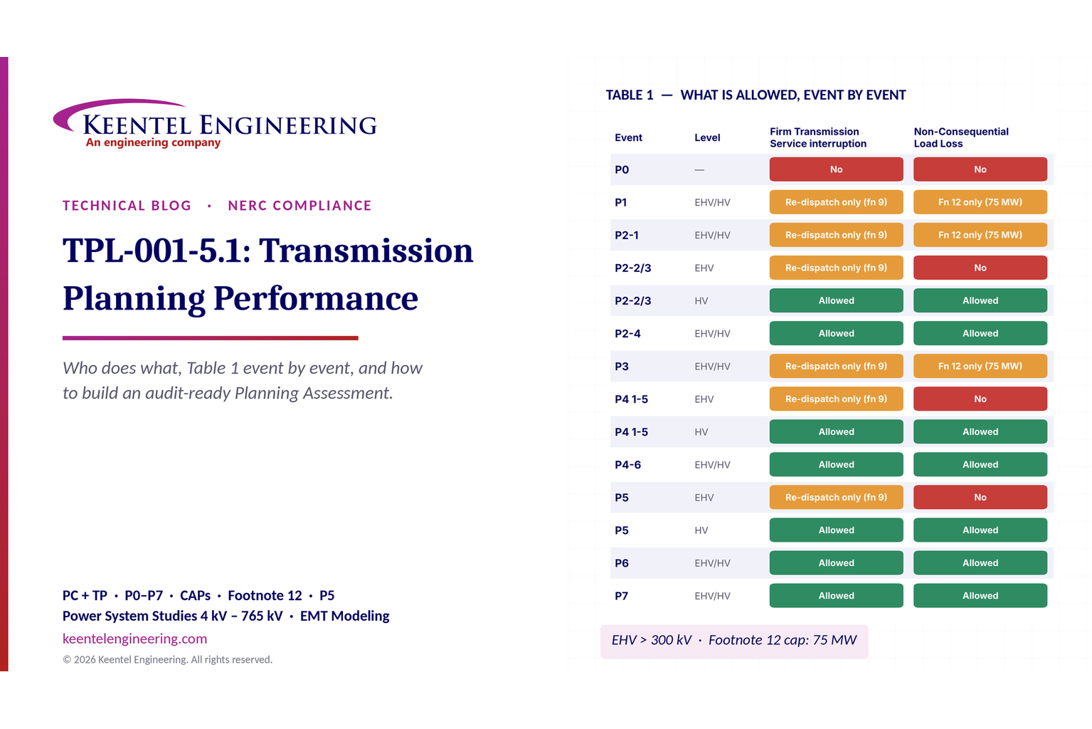
Explore NERC TPL-001-5.1 requirements, P0–P7 planning events, Table 1, corrective action plans and annual assessments with Keentel Engineering.
Radial vs. loop distribution systems comparison showing outage minutes and reliability.
By SANDIP R PATEL • November 6, 2026
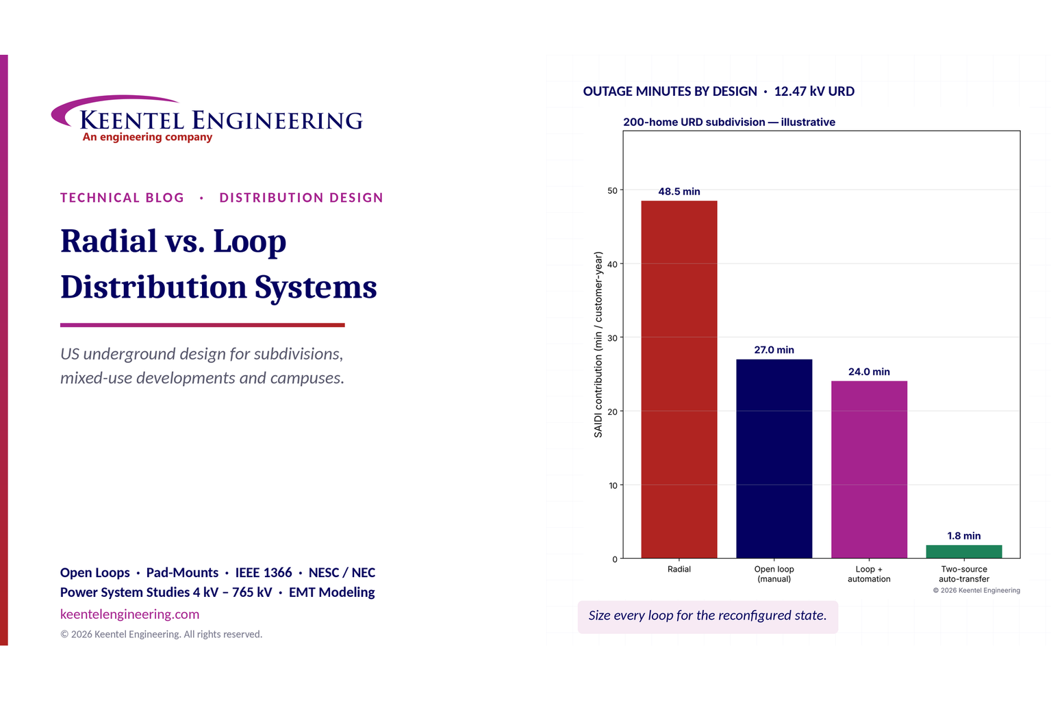
Compare radial vs. loop distribution systems in the US. Explore reliability, underground cables, protection, voltage drop and design with Keentel Engineering.
Transmission planning and resource adequacy analysis showing LOLE reduction and interregional transf
By SANDIP R PATEL • November 6, 2026
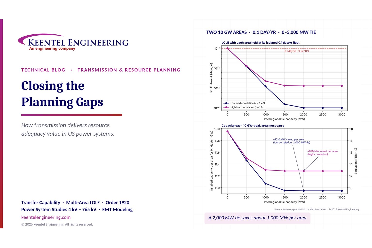
Learn how transmission planning improves US resource adequacy through LOLE, reserve sharing and FERC Order 1920 analysis from Keentel Engineering.