A Coordinated Electric System Interconnection Review—the utility’s deep-dive on technical and cost impacts of your project.

Challenge: Frequent false tripping using conventional electromechanical relays
Solution: SEL-487E integration with multi-terminal differential protection and dynamic inrush restraint
Result: 90% reduction in false trips, saving over $250,000 in downtime

The three operating regions you have to design to

Device Output vs voltage Response Best suited to Main limitations
Mechanically switched capacitor or reactor Proportional to voltage squared Seconds; discrete steps; limited switching operations per day Steady-state reactive supply, voltage profile, loss reduction No dynamic capability; step voltage change on switching; capability collapses when most needed
Static var compensator Capacitive branches proportional to voltage squared A few cycles; continuously controllable Continuous control where cost matters and deep voltage support is not the driver Square-law capability loss; harmonic filters are part of the plant and interact with the network
STATCOM Approximately proportional to voltage — constant current capability One to two cycles closed loop; converter response faster still Voltage stability margin, weak interconnections, fast disturbance recovery, flicker and unbalance compensation Higher capital cost; converter losses; adds a converter and its control dynamics to the network
Synchronous condenser Governed by machine capability and excitation Excitation response in the hundreds of milliseconds; inherent inertial response instantaneous System strength and inertia, short-circuit contribution, black start support Rotating plant with maintenance and losses; slower controlled response than a converter
STATCOM with energy storage Reactive as a STATCOM, plus real power within the storage rating As STATCOM for reactive; real power limited by storage Where a real power deficiency is part of the problem Cost and complexity of the storage; different failure and maintenance profile
Service area What we do for SST campuses Typical deliverables
Grid interconnection Site screening, large-load applications, independent studies, utility and RTO coordination in ERCOT, NYISO, PJM and other markets Screening reports, application data packages, load flow, contingency and stability studies, study review memos
EMT modeling Model requirements, vendor model review, campus aggregation, ride-through, weak-grid, control interaction and load-oscillation studies EMT model specifications, model acceptance reports, PSCAD study reports, SCR screening
MV/MVDC system studies AC and DC short-circuit, DC protection philosophy, AC protection, arc flash, grounding, insulation coordination Study reports, protection philosophy documents, settings files, arc flash labels, interface control documents
Power quality Emission requirements, frequency scans, IEEE 519-2022 compliance, filter sizing, flicker assessment Harmonic study reports, filter specifications, monitoring plans
Substation and transmission design HV/EHV substations, MV collectors, transmission lines, utility interface protection Physical and electrical drawing packages, specifications, bills of material, protection and control design
NERC compliance Registration and applicability, ride-through requirements, model validation, monitoring, compliance programs Applicability assessments, compliance programs, evidence packages, model validation reports
Owner's engineer and QA/QC SST, storage and substation specifications, design reviews, FAT and SAT plans and witnessing, multi-unit QA Specifications, review comments, test plans, witness reports, due diligence reports
Onsite generation and BESS Role definition and sizing, DC bus control architecture, fire and code compliance coordination, performance testing Sizing studies, control architecture documents, specifications, test procedures

Storage and generation

Term Meaning
AFE Active front end. The actively switched AC/DC stage of an SST that connects to the MV grid and sets its grid behavior.
Aggregated model A model in which many converters are represented by a smaller number of equivalent converters to make campus-scale simulation practical.
Arc flash The release of energy from an electric arc fault, assessed as incident energy at a working distance to set PPE and safe work practices.
BESS Battery energy storage system.
Blocking Turning off all converter switches so the converter stops feeding current, used to limit DC faults.
Composite load model A positive-sequence load model that combines several load types, such as motors, electronics and static loads.
DAB Dual active bridge. An isolated DC/DC converter topology with active bridges on both sides of a high-frequency transformer.
DC-link The internal DC capacitor bank between converter stages.
EMT Electromagnetic transient simulation. Time-domain simulation with microsecond time steps, used to study fast converter and network behavior.
FAT Factory acceptance test.
Grid-forming A converter control mode that sets its own voltage and frequency reference rather than following the grid's, providing support to weak grids.
HIL Hardware-in-the-loop testing, in which a real controller is tested against a real-time simulation.
IBR Inverter-based resource. Generation or storage connected to the grid through power electronics.
Insulation coordination Matching the insulation strength of equipment to the voltage stresses the system produces, with surge protection where needed.
ISC/IL The ratio of available short-circuit current to maximum demand load current at the point of common coupling, used to set IEEE 519 limits.
ISOP Input-series, output-parallel. A modular converter arrangement that shares a high input voltage across cells in series and combines their outputs in parallel.
Large load A load large enough to affect transmission system reliability. Definitions vary, for example 75 MW and above under Texas SB 6, or loads above 20 MW in the federal rulemaking proposal.
LVDC Low-voltage DC, such as 800 VDC or ±400 VDC rack distribution.
MFT Medium-frequency transformer. The compact isolation transformer inside an SST, operating at kilohertz frequencies.
MMC Modular multilevel converter. A converter built from many submodules with their own capacitors, producing a stepped multilevel waveform.
MVDC Medium-voltage DC distribution, roughly 1 kV to 35 kV DC in common usage.
OE Owner's engineer. An independent engineer representing the owner's technical interests.
PCC / POI Point of common coupling / point of interconnection, where the campus connects to the utility system and where compliance is usually assessed.
PLL Phase-locked loop. The control element that tracks grid voltage phase and frequency.
Positive-sequence model A fundamental-frequency, balanced dynamic model used in PSS®E, PSLF and similar tools.
Ride-through The ability to stay connected and keep operating during and after a grid disturbance within defined limits.
SAT Site acceptance test.
SCR Short-circuit ratio. Available short-circuit power divided by converter rating, a measure of grid strength.
SiC Silicon carbide, a wide-bandgap semiconductor material that allows higher voltage, higher frequency switching.
SST Solid-state transformer. A power electronic converter with a high-frequency isolation stage that replaces a 60 Hz transformer and rectifier chain.
Supraharmonics Emissions in the 2 kHz to 150 kHz range, above the range covered by most harmonic limits.
TDD Total demand distortion. Harmonic current distortion relative to maximum demand current, used in IEEE 519.
WSCR Weighted short-circuit ratio. An SCR screen that accounts for several inverter-based plants sharing a network area.

Links were current at publication (November 2026). Large-load rules, NERC actions and standards editions are changing quickly, so confirm current versions before relying on them.


Large-load reliability and NERC


Federal and state large-load rules


Solid-state transformers and DC data center power


Standards referenced (consult the publisher for the current edition)

Step 5 — options. Replacing or retrofitting the drives with active-front-end or 18-pulse units at about 5% THDi gives a TDD of about 1.5%. An active harmonic filter sized for the 5th and 7th could achieve a similar result at the facility level. A passive 5th-harmonic tuned filter would also work but must be checked for resonance with the utility system and with any future capacitors.


What this means for you.


The same drives can be compliant on a strong system and non-compliant on a weak one. Ask your utility for the maximum short-circuit current at the PCC early in design. If the ratio is below 50, plan for low-harmonic drives or filtering from the start; it is much cheaper than retrofitting.


9. Inverter-based resources: solar, storage and wind


Solar PV, battery energy storage and full-converter wind turbines use pulse-width-modulated inverters with output filters. They are generally low-distortion sources. IEEE Std 1547-2018 (distribution-connected resources) and IEEE Std 2800-2022 (transmission-connected resources) limit their current distortion — total rated-current distortion (TRD) of 5% with individual limits by order, measured against rated current rather than present output. In practice, quality inverters measure 1–3% at rated output.


Three cautions apply:


  1. Percentages rise at low output. At 10% of rated output a 2% distortion (of rated current) looks like 20% THD. Limits referenced to rated current, like TDD, avoid this trap.
  2. Inverters change the system's impedance. Plant collector cables, inverter output filters and capacitor banks add capacitance. They can create resonances near the 5th to 13th harmonics on the 34.5 kV collector or at a 138 kV, 230 kV or 345 kV point of interconnection, amplifying background distortion that the plant did not create.
  3. Background distortion matters. Inverters can absorb or amplify existing voltage distortion depending on their control design. Utilities increasingly require harmonic impedance studies for new plants, sometimes using electromagnetic transient (EMT) simulation.


Keentel's articles on harmonic resonance and on
weak-grid inverter stability cover these interactions in depth.


10. Data centers and other electronic facilities


Data centers are a special case because almost all their load is electronic. Points to check:


  • UPS rectifiers. Double-conversion UPS units with IGBT rectifiers typically draw less than 5% THDi at rated load, rising at low load. Older six-pulse or 12-pulse thyristor UPS rectifiers may need input filters.
  • Server and network power supplies. Modern units with active power factor correction have low 3rd harmonic. Legacy equipment does not. Measure a representative panel rather than assuming.
  • 208Y/120 V and 415Y/240 V distribution. Check neutral current and transformer K-factor as in Sections 4 and 7.
  • Generator operation. Test UPS and generator compatibility at the actual load level. Generator THDv can be three to four times the utility THDv for the same load.
  • Cooling plant. Chiller, pump, fan and cooling distribution unit drives often contribute more low-order harmonics than the IT load. Specify low-harmonic drives where the facility is large relative to the utility source.
  • Large-load interconnection. Utilities and grid operators now treat large data centers as high-impact loads. Harmonic studies and power quality monitoring are increasingly part of interconnection requirements, alongside ride-through and dynamic studies.


11. How a harmonic study is done


A harmonic study answers four questions: How much harmonic current will the facility inject? What voltage distortion will it cause? Will any resonance amplify it? What is the cheapest reliable fix? Keentel's typical workflow:


  1. Gather data. Single-line diagram; utility short-circuit data (maximum and minimum) at the PCC; utility background distortion if known; transformer impedances; cable lengths; capacitor banks and filters; drive, UPS and inverter data sheets with harmonic spectra.
  2. Measure existing conditions. For existing facilities, install class-compliant power quality meters at the PCC and key buses for at least one week, capturing 10-minute and 3-second data up to the 50th harmonic.
  3. Build the model. Represent sources as harmonic current injections and the network as frequency-dependent impedances, including transformer phase shifts that can cancel 5th and 7th harmonics between delta-delta and delta-wye units.
  4. Run a frequency scan. Plot driving-point impedance versus frequency at each important bus to find resonances, for all credible system configurations (tie breakers open/closed, capacitor steps in/out, generator versus utility).
  5. Run harmonic load flow. Calculate harmonic currents and voltages and compare them with IEEE 519 at the PCC and with equipment limits (IEEE 18 for capacitors, C57.110 for transformers) inside the facility.
  6. Design mitigation. Compare options for performance, cost, losses, footprint and future flexibility.
  7. Verify. Measure again after installation and document compliance with the statistical criteria.


12. Fixing harmonics: options compared
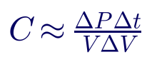
For the single-loop design in normal configuration, each half carries 90.3 A over 6,000 ft:
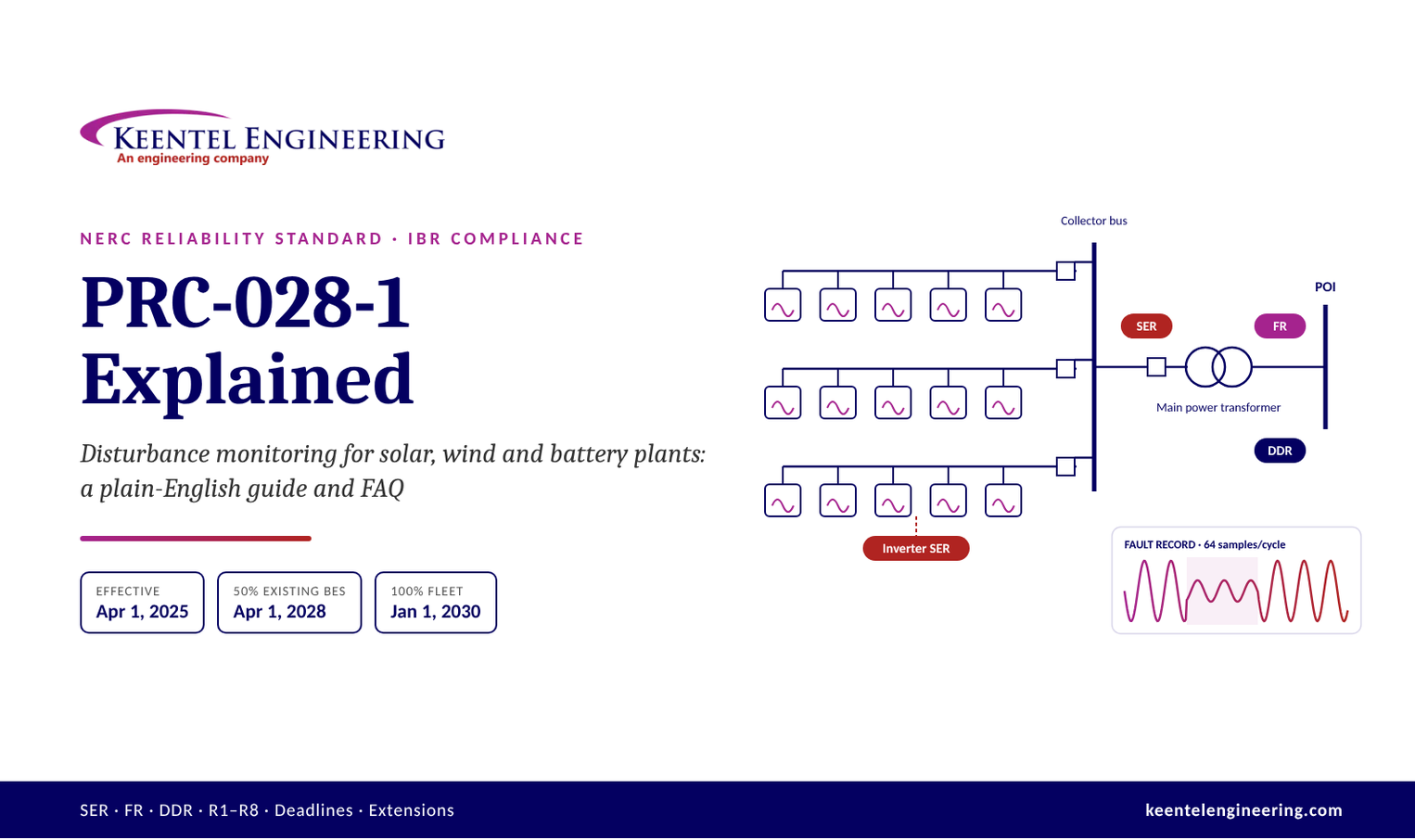
PRC-028-1 Explained: What Every Solar, Wind & Battery Owner Needs to Know

Radial vs. loop distribution systems comparison showing outage minutes and reliability.
Calendar icon. D

November 10, 2026 | Blog

The short version


If you own a solar farm, wind farm or battery storage plant connected to the high-voltage grid, NERC Reliability Standard PRC-028-1 now requires you to install "black box" recorders at your plant. The standard took effect in the U.S. on April 1, 2025, and every existing plant must be fully equipped by January 1, 2030. New plants must have the recorders working on the day they go commercial.


Think of it like the flight data recorder on an airplane. When something goes wrong on the grid, investigators need to know exactly what each plant saw and did, down to the millisecond. Until now, most solar, wind and battery plants simply didn't keep that kind of record.

This guide explains, in plain English, what PRC-028-1 requires, who it applies to, the deadlines that matter, and what to do next. A detailed FAQ is at the end.


Why this standard exists


PRC-028-1 exists because several large grid disturbances showed that inverter-based plants can react badly to ordinary faults, and nobody had the data to prove why.


  • What happened. In events such as the Blue Cut Fire, Canyon 2 Fire and Odessa (Texas) disturbances, a routine transmission fault that was cleared in a few cycles caused many solar plants to trip offline or cut output at the same time. A small, normal event turned into a large one.
  • What was missing. When NERC investigated, most of the plants involved had no high-speed recordings. Investigators could not tell which inverters tripped, why, or in what order.
  • What regulators did. FERC Order No. 901 directed NERC to require inverter-based resource (IBR) owners to install disturbance monitoring equipment, share the data, and let planners use it to check their computer models. FERC wants this in force before 2030.
  • What NERC did. Rather than bolt IBR rules onto the existing PRC-002 standard, NERC wrote a new, dedicated standard: PRC-028-1. FERC approved it on February 20, 2025.


In plain terms: the grid now has a lot of solar, wind and batteries, and those plants respond to problems in milliseconds through software. To keep the grid reliable, operators need to see exactly how they behave.


PRC-002 vs. PRC-028: who covers what


PRC-002 covers the transmission grid's key substations; PRC-028 covers the inverter-based plant itself. They were updated together under NERC Project 2021-04.

PRC-002-5 PRC-028-1
What it monitors Key transmission buses and Elements, plus synchronous generators Inverter-based resources: solar, wind, battery storage, VSC HVDC-connected plants
Who is responsible Reliability Coordinator, Transmission Owner, Generator Owner Generator Owner only
What changed IBRs removed from its scope (clarification only, no new equipment) Brand-new standard
U.S. effective date April 1, 2025 (replaced PRC-002-4) April 1, 2025
Phase-in period None Through January 1, 2030

A simple way to picture the boundary: the utility's substation where your line lands may be a PRC-002 bus owned by the Transmission Owner. Everything on your side of the tie line, from the main power transformer down to the inverters, falls under PRC-028 and is your responsibility as Generator Owner.


Transmission Owners were deliberately removed from PRC-028 during drafting. If you share a switchyard with the utility, spell out in your interconnection agreement who owns which recorder and who supplies which data.


Who must comply


PRC-028-1 applies to the Generator Owner of any inverter-based plant that falls into one of two groups.


  1. BES inverter-based resources. Plants that are already part of the Bulk Electric System under NERC's existing definition. In general, these are larger plants connected at 100 kV or above. Most utility-scale solar, wind and storage owners already registered with NERC are in this group.
  2. Non-BES inverter-based resources. Smaller plants that are newly being registered with NERC. They qualify if they have, or contribute to, an aggregate nameplate capacity of 20 MVA or more, connected through a system designed mainly to deliver that power to a common point of connection at 60 kV or above. NERC expanded its registration rules (FERC approved them June 27, 2024), and these owners must be registered by May 2026.


"Inverter-based resource" covers any plant whose generators connect to the AC grid through power electronics: solar PV, wind turbines (Type 3 and Type 4), battery energy storage systems, and plants tied in through a dedicated VSC HVDC link.


The Generator Operator, the Transmission Owner and the Transmission Operator have no PRC-028 obligations. The Generator Owner carries all of them.


What equipment is covered


Inside an in-scope plant, PRC-028-1 looks at five kinds of equipment:


  • Circuit breakers (or other interrupting devices)
  • Main power transformer(s): the big transformer(s) that step plant voltage up to transmission voltage
  • Collector bus and collector feeder breakers: the medium-voltage system that gathers power from the inverters
  • Shunt reactive devices, static or dynamic, including filter banks. Synchronous condensers and STATCOMs/SVCs installed inside the plant count here.
  • AC-DC and DC-AC converters where the plant connects through a dedicated VSC HVDC line, such as an offshore wind farm. In that case, transformers on both ends count as main power transformers.


The inverters themselves (and wind turbine converters) are covered too, but only for event logging, as explained below. The standard calls each one an "IBR unit".


The three kinds of recording, in plain English


PRC-028-1 asks for three different types of data. Each answers a different question about what happened.

Recording Plain-English analogy What it answers Where it's required
SER: Sequence of Events Recording A time-stamped diary of every switch flip Which breaker opened, which inverter tripped, in what order, and why (fault codes) Every in-scope breaker, plus every inverter
FR: Fault Recording A high-speed camera filming the first 2 seconds The exact voltage and current waveforms during a fault High side of each main power transformer, each collector feeder breaker, each dynamic reactive device
DDR: Dynamic Disturbance Recording A security camera that never stops recording How plant output swings over seconds to minutes after a disturbance High side of each main power transformer

Example. A lightning strike causes a fault on a nearby 230 kV line that clears in 4 cycles. The FR captures the voltage dip and the plant's current injection during those milliseconds. The SER shows that collector feeder 3's breaker stayed closed but 40 inverters logged an AC undervoltage trip. The DDR shows plant output dropping from 150 MW to 60 MW and taking 90 seconds to recover. Together, they tell the full story.


What each requirement says (R1 to R8)

PRC-028-1 has eight requirements. Here is what each one means in practice, based on NERC's Technical Rationale. Always check the wording of the standard itself, which is what auditors enforce.


R1: Sequence of Events Recording (SER)


Record every open/close of the breakers on the main power transformer, the collector bus and feeders, reactive devices and filter banks, and any HVDC converters. Also record each inverter's fault codes, alarms, and voltage or frequency ride-through status whenever it rides through or trips. Momentary cessation counts as ride-through for recording purposes.


  • Relief for older inverters: if an inverter was in commercial operation before April 1, 2025 and simply cannot record SER data, it is excused. The same applies if the manufacturer has gone out of business or been acquired and you can't confirm the capability. Keep written documentation proving this.
  • No new hardware at the inverter: NERC states it does not intend for owners to add equipment to inverters just for SER. New inverters already have the capability.


R2: Fault Recording (FR) locations and quantities


At the high side of each main power transformer, record each phase-to-neutral voltage, each phase current, residual (neutral) current, and real and reactive power. Values may be measured directly or calculated. Record the same quantities for any dynamic reactive device, and record current on each collector feeder breaker. Feeder recordings stand in for recording each individual inverter.


R3: Fault Recording performance


  • At least 64 samples per cycle
  • At least 2 seconds of data per event (120 cycles). Several shorter records stitched together on a common clock are allowed.
  • Triggers must include a neutral (residual) overcurrent setting for ground faults, and a phase overvoltage or undervoltage setting for ride-through events


R4: Dynamic Disturbance Recording (DDR)


Continuous recording at the high side of each main power transformer. One phase-to-neutral voltage (or positive-sequence, or phase-to-phase), the matching current, frequency, and real and reactive power. Data is stored as RMS or phasor values, not raw waveforms.


R5: DDR performance


Input sampling of at least 960 samples per second (16 per cycle) and an output recording rate of at least 60 values per second.


R6: Time synchronization


All recorders must be synced to UTC. Plant-level recorders (FR, DDR, breaker SER) must be within ±1 millisecond. Inverters can be within ±100 milliseconds, because distributing a precision clock to hundreds of inverters is hard. This is intentionally looser than IEEE 2800's ±1 microsecond.


R7: Keeping and sharing data


  • Keep data retrievable for at least 20 calendar days
  • When the Reliability Coordinator, Regional Entity or NERC asks, deliver it within 15 calendar days (an extension can be agreed)
  • SER in a simple CSV format. FR and DDR in IEEE C37.111 (COMTRADE) or CSV with headers. File names per IEEE C37.232 (COMNAME).


R8: Fixing broken recorders


If a recorder fails, restore it within 90 calendar days of discovering the failure. If that's not possible (budget cycle, vendor lead time, needed outage), submit a Corrective Action Plan to your Regional Entity and follow it. An outage of the equipment being monitored doesn't count as a recorder failure.


Key dates and deadlines


PRC-028-1 became effective on April 1, 2025. Existing plants are phased in through January 1, 2030, and new plants must comply when they go commercial. "COD" means commercial operation date: the date a plant has every approval it needs to operate after start-up testing.

Plant type When it reached COD What's due Deadline
BES IBR Any R8 (fix failed recorders within 90 days) January 1, 2026 (already in force)
BES IBR On or before April 1, 2025 R1–R7 at 50% of your BES IBR fleet April 1, 2028
BES IBR On or before April 1, 2025 R1–R7 at 100% of your BES IBR fleet January 1, 2030
BES IBR, owner has only one plant On or before April 1, 2025 R1–R7 April 1, 2028
BES IBR April 2, 2025 to July 1, 2026 R1–R7 July 1, 2026 (passed)
BES IBR After July 1, 2026 R1–R7 On the COD
Non-BES IBR On or before May 15, 2026 R1–R7 at 100% January 1, 2030
Non-BES IBR After May 15, 2026 R1–R7 Later of July 1, 2026 or COD, so in practice on the COD
Non-BES IBR Any R8 April 1, 2027

Two things readers often get wrong:


  • NERC's implementation plan uses an example effective date of July 1, 2025, which gives an October 1, 2026 cutoff for new plants. The real effective date is April 1, 2025, so the real 15-month cutoff was July 1, 2026. Some industry articles still quote the October date.
  • The plan doesn't say whether "50% of your BES IBRs" means 50% of plants or 50% of megawatts. Pick a basis, write it down, and confirm it with your Regional Entity.


Worked example: a new battery plant going live in December 2026


A battery storage plant with a December 1, 2026 commercial operation date must be fully PRC-028-1 compliant on December 1, 2026. That applies whether it is BES or non-BES.


  1. Why there's no grace period. For new plants, the deadline is the later of July 1, 2026 or the COD. July 1, 2026 has already passed, so the COD controls.
  2. R8 (repairs). If the plant is BES, R8 applies from COD. If it is non-BES, R8 formally starts April 1, 2027, but planning to meet it from day one is wise.
  3. No older-inverter relief. The SER exemption only covers inverters in service before April 1, 2025. The plant's battery inverters (power conversion systems) must log fault codes, alarms and ride-through status, time-synced within ±100 ms.
  4. No extension. Extensions are only for plants already operating before April 1, 2025. See the next section.
  5. What to have ready on COD:


  • A list of every in-scope breaker, transformer, feeder and reactive device, marked on the one-line diagram
  • Recorder settings showing at least 64 samples/cycle and 2-second records for FR, plus the required triggers
  • DDR running continuously at 960 samples/s input and 60/s output
  • GPS or other UTC clock test results showing ±1 ms at plant level
  • Written procedures for keeping data 20 days and delivering it within 15 days (R7)
  • A written R8 procedure for detecting and repairing recorder failures
  • NERC registration as Generator Owner completed before COD


If the recorders won't be ready, the cleanest option is usually to delay declaring COD. Going commercial without them means being out of compliance from the first day.


Extensions: who qualifies and how to ask


Only Generator Owners whose IBRs were already in commercial operation before April 1, 2025 can ask for more time. New plants cannot.


Valid reasons are circumstances outside your control, such as:

  • Supply-chain delays in buying, engineering, installing or commissioning the recorders
  • Being unable to get a scheduled outage to do the work
  • Other exceptional circumstances


What the request must contain (sent to your Compliance Enforcement Authority, usually your Regional Entity):


  1. Which plants the extension covers
  2. Your plan and timetable for installing the equipment
  3. What is stopping you and why it is beyond your control
  4. Anything else that supports the request


When to send it. As soon as you see the problem, and no later than three months before the deadline you need extended. That means by January 1, 2028 for the 50% milestone and by October 1, 2029 for the 100% milestone. If an extension is granted, you must follow your timetable. If you need still more time, submit an updated request.


Don't count on extending past January 1, 2030 easily. That date comes straight from FERC's directive.


Your compliance checklist


Most owners can get compliant by working through these nine steps in order.


  • Confirm applicability. List every plant, classify it as BES or non-BES (20 MVA / 60 kV test), and record its COD.
  • Confirm NERC registration. Make sure each owning entity is registered as a Generator Owner.
  • Build the equipment inventory. Mark every in-scope breaker, main power transformer, collector feeder, reactive device, filter bank and converter on the one-line diagram.
  • Check inverter SER capability. Ask each inverter vendor in writing whether the units log fault codes, alarms and ride-through status with time stamps. For pre-April-2025 units that can't, keep the evidence for the exemption.
  • Gap-check existing relays and recorders. Many modern protective relays and DFRs already meet 64 samples/cycle, 2-second records and the trigger settings. Confirm continuous DDR at 960/60 and ±1 ms clock accuracy.
  • Order what's missing. Recorder and GPS clock lead times can be long, and installation usually needs an outage. Start early.
  • Set your 50% plan. For existing BES fleets, choose which plants make up the first 50% (by April 1, 2028). Prioritise the largest or highest-risk sites, and document your counting basis.
  • Write the procedures. Data retention (20 days, ideally 30 or more), data requests (15 days), file formats (COMTRADE/CSV, COMNAME naming), and recorder failure response (90 days or a Corrective Action Plan).
  • Keep audit evidence. Settings files, clock test records, commissioning reports, vendor letters, and request/response logs.

Frequently asked questions

  • Q1. What is PRC-028-1, in one sentence?

    It's a NERC rule that requires owners of solar, wind and battery plants to install "black box" recorders so grid disturbances can be investigated.


  • Q2. Is it in effect now?

    Yes. It became effective in the U.S. on April 1, 2025. Some deadlines have already passed, and others run through January 1, 2030.


  • Q3. Does it apply to my plant?

    It does if your plant is inverter-based and is either part of the Bulk Electric System, or is 20 MVA or larger (alone or combined with others) and connects at 60 kV or above.


  • Q4. Does it apply to rooftop or community solar?

    Generally no. Distribution-connected plants below the 20 MVA / 60 kV threshold are not covered.


  • Q5. Does it apply to battery storage?

    Yes. Batteries connect through inverters, so they are inverter-based resources.


  • Q6. Does it apply to hybrid solar-plus-storage plants?

    Yes. The whole facility is assessed. The recorder locations (main power transformer, collector feeders and so on) are the same.


  • Q7. Who is responsible, us or the utility?

    The Generator Owner. Transmission Owners have no PRC-028 obligations, though they still have PRC-002 duties at their own substations.


  • Q8. What's the difference between PRC-002 and PRC-028?

    PRC-002 covers key transmission substations and conventional generators. PRC-028 covers inverter-based plants. PRC-002-5 simply removed IBRs so they aren't covered twice.


  • Q9. Do I have to add equipment to every inverter?

    No. Inverters must log events (SER) only. Older inverters that can't do it are excused if you document it. New inverters generally already can.

  • Q10. Do I need a separate DFR, or can my relays do it?

    Modern microprocessor relays often satisfy fault recording if they meet 64 samples/cycle, 2-second records and the trigger rules. Continuous DDR usually needs a dedicated recorder or PMU-type device. Each site needs an engineering check.


  • Q11. What does "64 samples per cycle" mean?

    The recorder takes 64 snapshots of the voltage and current wave in every 1/60th of a second, which is fast enough to see the shape of a fault clearly.


  • Q12. Why ±1 millisecond time sync?

    Inverter plants react within 10 to 40 milliseconds. Without precise time stamps, investigators can't line up records from dozens of plants to see what happened first.


  • Q13. How long do I keep data?

    At least 20 calendar days. We recommend 30 or more, because requests can arrive late in that window.


  • Q14. Who can ask for my data, and how fast must I respond?

    Your Reliability Coordinator, Regional Entity or NERC. You have 15 calendar days unless they agree to an extension.


  • Q15. What happens if a recorder breaks?

    Fix it within 90 days of discovering the failure. If you can't, file a Corrective Action Plan with your Regional Entity and follow it.


  • Q16. My new plant goes live after July 1, 2026. When must I comply?

    On your commercial operation date. There is no grace period and no extension for new plants.


  • Q17. Can I get an extension?

    Only for plants operating before April 1, 2025, only for reasons beyond your control, and only if you ask at least three months before the deadline.


  • Q18. What if I miss a deadline?

    That's a potential violation. Self-reporting to your Regional Entity with a mitigation plan is generally viewed more favourably than having it found at audit. Talk to compliance counsel.


  • Q19. What does "50% of my BES IBRs" mean?

    The plan doesn't define it. Count by plants or by MW, document the choice, and confirm it with your Regional Entity.


  • Q20. Will the rule get stricter?

    Possibly. FERC flagged high-speed data at the plant controller level, which this first version doesn't require. Designing with spare capacity now can avoid a costly retrofit later.


  • Q21. Is this related to PRC-029 and PRC-030?

    Yes. They are companion IBR standards. PRC-029-1 sets ride-through performance, and PRC-030-1 requires owners to find and fix unexpected IBR performance. Both took effect October 1, 2026. PRC-028 recordings are the evidence used for both.


How Keentel Engineering can help

Keentel Engineering supports Generator Owners through every step of PRC-028-1 compliance:


  • Applicability reviews (BES vs. non-BES) and compliance date mapping
  • One-line diagram reviews and equipment inventories
  • Gap assessments of existing relays, DFRs, PMUs and clock systems
  • Recorder and GPS clock specifications, settings and trigger design
  • Inverter SER capability reviews and exemption documentation
  • R7/R8 procedures, extension requests and audit-ready evidence packages
  • Companion PRC-029-1 and PRC-030-1 support


  Start a scope:  contact@keent


References and further reading


NERC standards and project documents


Regulatory approval and regional guidance


Links were current at publication (November 2026).


Disclaimer


This article is general technical information, not legal or compliance advice, and does not create an engineering engagement. Requirements are summarised from NERC documents as of November 2026; always confirm against the current standard text and with your Regional Entity. NERC, FERC, IEEE and other names are the property of their respective owners; Keentel Engineering is not affiliated with or endorsed by them.


Office Address Phone
Head Office — Tampa 400 N Ashley Dr STE #2600, Tampa FL 33602 (813) 389-7871
Austin 5900 Balcones Drive STE 100, Austin TX 78731 (512) 591-0752
Sacramento 1401 21st St Ste R, Sacramento CA 95811 (916) 913-4524
Baltimore 306 W Redwood St STE 200, Baltimore MD 21201 (410) 225-2181


A smiling man with glasses and a beard wearing a blue blazer stands in front of server racks in a data center.

About the Author:

Sandip "Sonny" R. Patel, P.E.

IEEE Senior Member · Founder & CEO, Keentel Engineering

In 1995, Sonny Patel earned his Electrical Engineering degree from the University of Illinois. But degrees don't build legacies — action does.

For three decades, he has worked the power industry from every side of the table: 16 years as a utility engineer at Exelon/Commonwealth Edison; generation leadership across hydroelectric, industrial steam turbine, and a 9 GW renewable fleet; NERC Regional Entity Senior Compliance Engineer and Audit Team Lead, auditing some of the nation's largest utilities; and testing and commissioning lead on equipment up to 765 kV — the very top of the North American grid.Utility. Generator. Regulator. Consultant. Few engineers have seen all four seats. Fewer still have sat in them.

His experience spans nuclear, hydro, conventional generation, renewables, oil and gas, mining — and today's data centers, where he is authoring a three-book series on data center design. He is a Licensed Professional Engineer in six states and a Licensed Electrical Contractor in Florida (Unlimited EC) — he doesn't just design the work; he's qualified to stand behind its execution.Today, as Founder and CEO of Keentel Engineering, Sonny leads a nationwide team of engineers delivering substation design, power system studies, NERC compliance, and commissioning — done right, coast to coast.Three decades. Every side of the table. One standard: accountable engineering.

Four workers in safety vests and helmets stand with arms crossed near wind turbines.

Let's Discuss Your Project

Let's book a call to discuss your electrical engineering project that we can help you with.

Man in a blazer and open shirt, looking at the camera, against a blurred background.

About the Author:

Sandip "Sonny" R. Patel, P.E.

IEEE Senior Member · Founder & CEO, Keentel Engineering

In 1995, Sonny Patel earned his Electrical Engineering degree from the University of Illinois. But degrees don't build legacies — action does.

For three decades, he has worked the power industry from every side of the table: 16 years as a utility engineer at Exelon/Commonwealth Edison; generation leadership across hydroelectric, industrial steam turbine, and a 9 GW renewable fleet; NERC Regional Entity Senior Compliance Engineer and Audit Team Lead, auditing some of the nation's largest utilities; and testing and commissioning lead on equipment up to 765 kV — the very top of the North American grid.

Utility. Generator. Regulator. Consultant. Few engineers have seen all four seats. Fewer still have sat in them.

His experience spans nuclear, hydro, conventional generation, renewables, oil and gas, mining — and today's data centers, where he is authoring a three-book series on data center design. He is a Licensed Professional Engineer in six states and a Licensed Electrical Contractor in Florida (Unlimited EC) — he doesn't just design the work; he's qualified to stand behind its execution.

Today, as Founder and CEO of Keentel Engineering, Sonny leads a nationwide team of engineers delivering substation design, power system studies, NERC compliance, and commissioning — done right, coast to coast.Three decades. Every side of the table. One standard: accountable engineering.

Leave a Comment

Related Posts

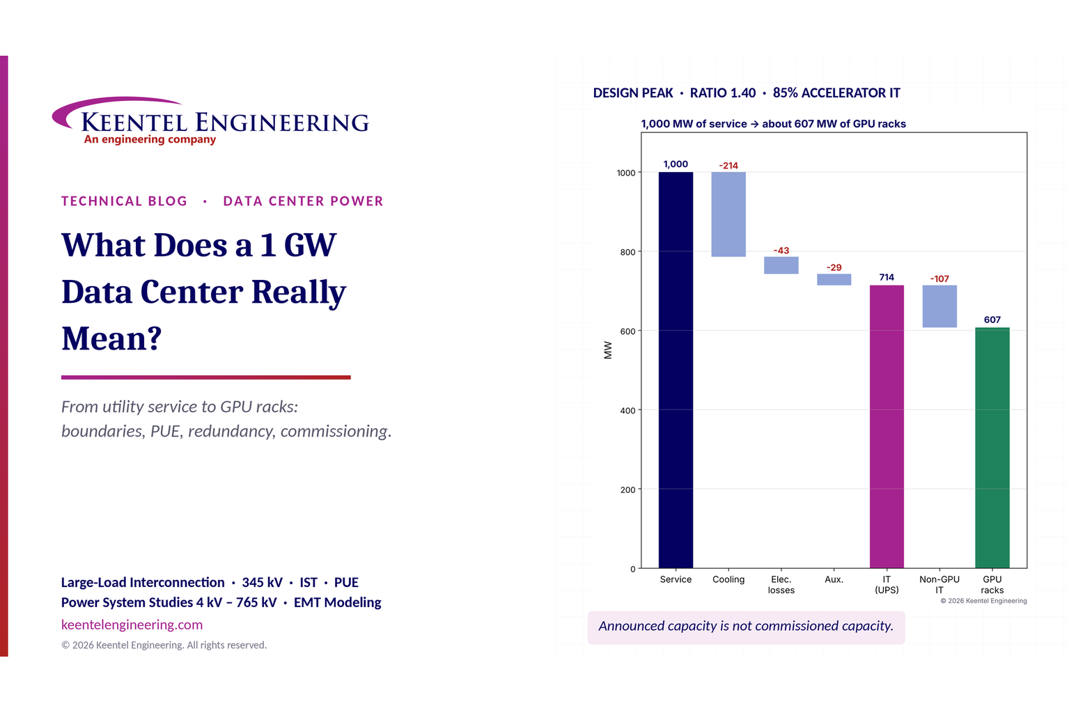
1 GW data center power capacity breakdown from utility service to GPU racks.
By SANDIP R PATEL • November 8, 2026
What does a 1 GW data center mean? Explore power capacity, PUE, GPU racks, grid interconnection and commissioning with Keentel Engineering's expert guide.
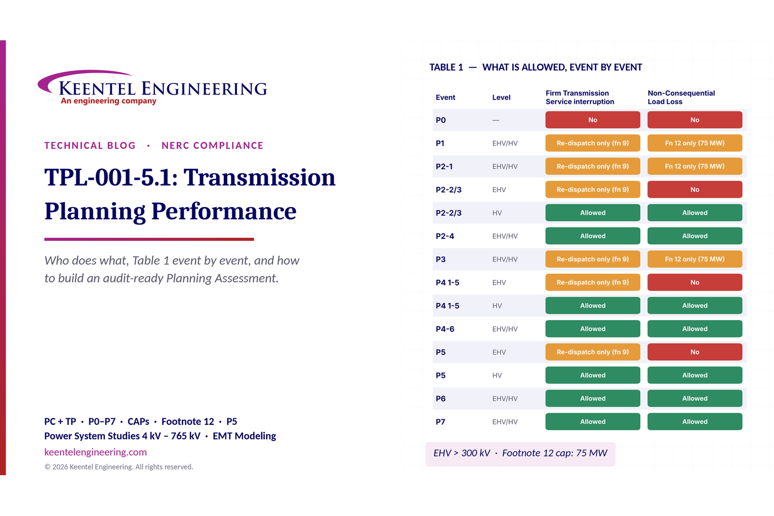
TPL-001-5.1 transmission planning performance and NERC compliance requirements
By SANDIP R PATEL • November 8, 2026
Explore NERC TPL-001-5.1 requirements, P0–P7 planning events, Table 1, corrective action plans and annual assessments with Keentel Engineering.
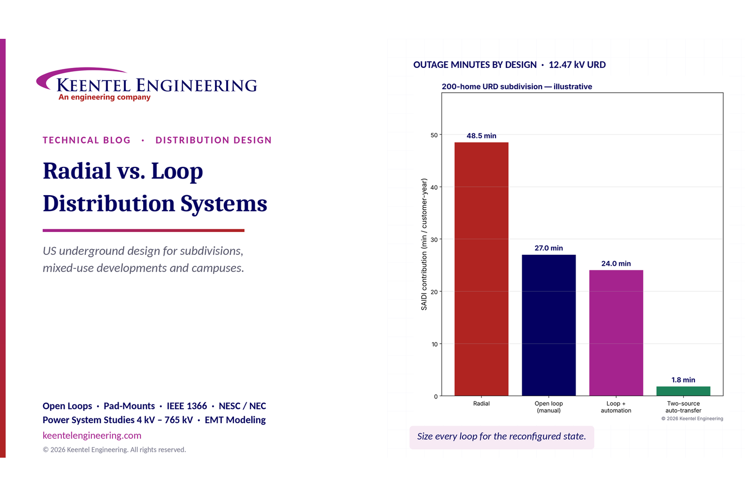
Radial vs. loop distribution systems comparison showing outage minutes and reliability.
By SANDIP R PATEL • November 6, 2026
Compare radial vs. loop distribution systems in the US. Explore reliability, underground cables, protection, voltage drop and design with Keentel Engineering.
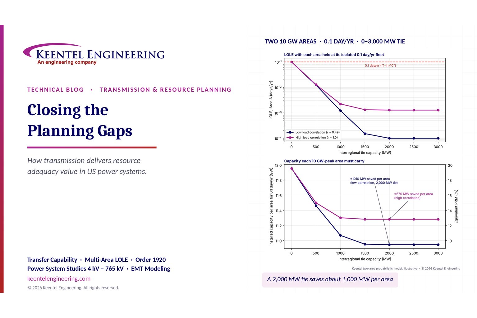
Transmission planning and resource adequacy analysis showing LOLE reduction and interregional transf
By SANDIP R PATEL • November 6, 2026
Learn how transmission planning improves US resource adequacy through LOLE, reserve sharing and FERC Order 1920 analysis from Keentel Engineering.
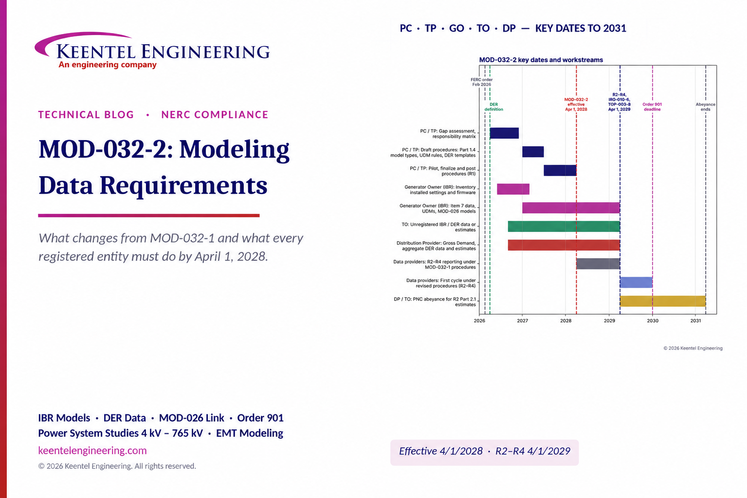
MOD-032-2 modeling data requirements and NERC compliance timeline through 2031.
By SANDIP R PATEL • November 6, 2026
Understand NERC MOD-032-2 requirements, key compliance dates, IBR modeling, DER data reporting and changes from MOD-032-1 with Keentel Engineering.
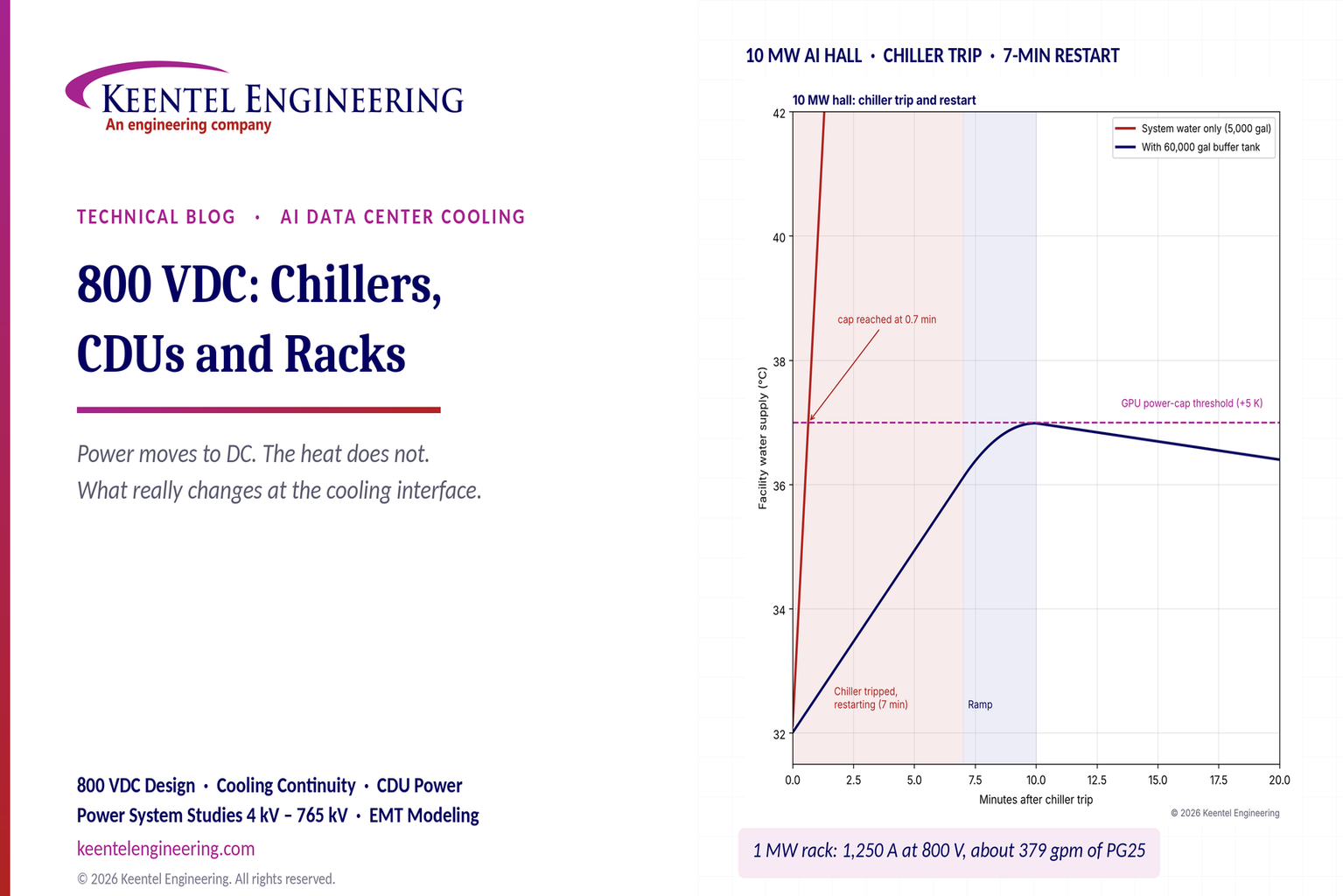
800 VDC AI data center cooling and chiller restart temperature comparison chart.
By SANDIP R PATEL • November 5, 2026
Learn how 800 VDC affects AI data center cooling, including chillers, CDUs, liquid-cooled racks, pump backup and DC safety. Keentel Engineering, USA.
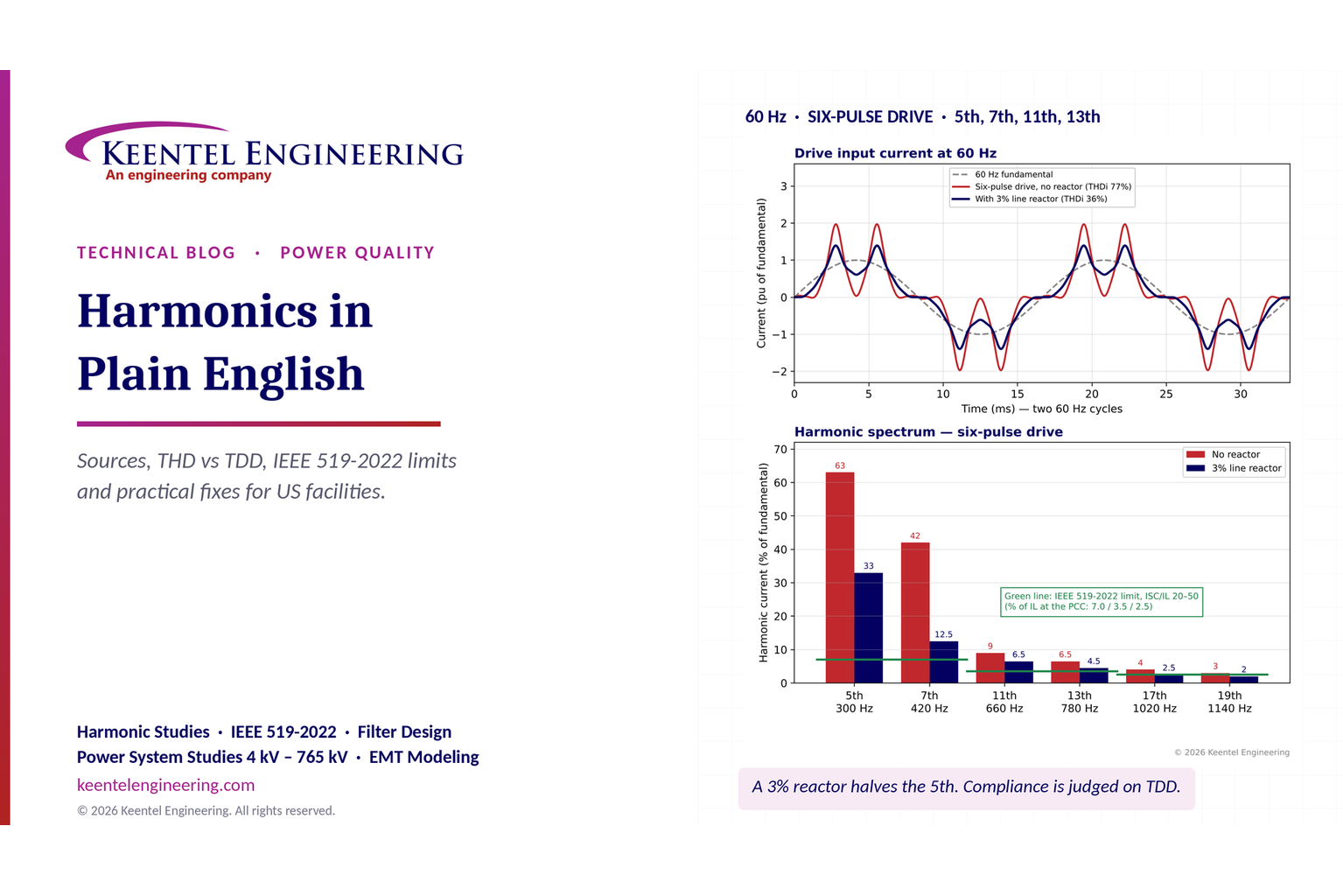
Keentel Engineering harmonics analysis showing current waveforms, harmonic spectrum, and IEEE 519-20
By SANDIP R PATEL • November 5, 2026
Understand electrical harmonics, THD vs TDD and IEEE 519-2022 limits. Keentel Engineering explains US harmonic studies, equipment risks and mitigation.
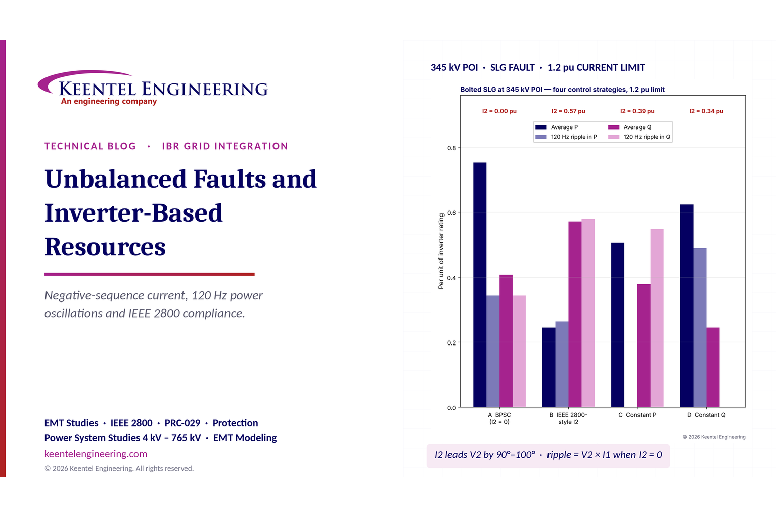
Unbalanced faults in inverter based resources with IEEE 2800 compliance analysis
By SANDIP R PATEL • November 5, 2026
Keentel Engineering explains unbalanced faults in inverter-based resources, negative-sequence current, 120 Hz power oscillations and IEEE 2800 compliance.
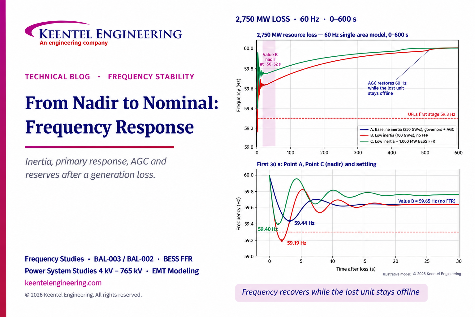
Frequency response curves showing grid stability after a 2,750 MW generation loss.
By SANDIP R PATEL • November 5, 2026
Explore four stages of US grid frequency recovery after generation loss, from inertia and primary response to AGC and reserves, with Keentel Engineering.