Part A — MOD-032-2 at a Glance
Every transmission plan, interconnection study, transfer limit and NERC planning assessment in North America is built on computer models. Those models are only as good as the data that goes into them: the impedance of every line and transformer, the rating of every circuit, the size and controls of every generator, the behavior of every load and, increasingly, the controls and ride-through settings of every solar, wind and battery plant — including the thousands of small solar and storage systems on distribution feeders.
NERC Reliability Standard MOD-032 — Data for Power System Modeling and Analysis — is the standard that gets that data from the entities that own the equipment to the entities that build the models. Its purpose is unchanged in version 2: "to establish consistent modeling data requirements and reporting procedures for development of planning horizon cases necessary to support analysis of the reliability of the interconnected transmission system."
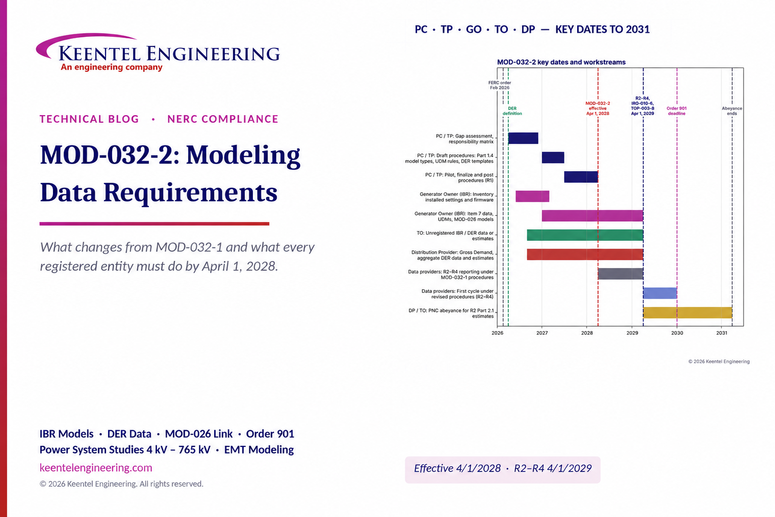
MOD-032-2 was developed under NERC Project 2022-02, Uniform Modeling Framework for IBR, in response to FERC Order No. 901. The NERC Board of Trustees adopted it on October 31, 2025, and FERC acted on the Order No. 901 modeling package in February 2026. Under the implementation plan the standard becomes effective on the first day of the first calendar quarter 24 months after the effective date of the FERC order — April 1, 2028 — with Requirements R2, R3 and R4 phased in 12 months later, on April 1, 2029.
The short version of what changes: MOD-032-1 collected modeling data for conventional generation, load and transmission. MOD-032-2 adds explicit data for inverter-based resources (IBRs), IBRs that are not registered with NERC and aggregated distributed energy resources (DERs); makes the Distribution Provider responsible for DER and load data; requires planners to specify which dynamic model types they accept; and ties submitted dynamic models to those accepted under MOD-026.
In plain terms: under MOD-032-2, the planner must say exactly which dynamic models it wants — standard library models, user-defined models or both — and, for user-defined models, how they must be documented. The data owner must send the model the Transmission Planner accepted under MOD-026 where one exists, must estimate DER and unregistered IBR data it cannot collect (and explain how), and must justify any model that appears on NERC's Unacceptable Models List.
Key dates
The dates below assume a FERC order effective in the first quarter of 2026, consistent with FERC's February 2026 action on the modeling package. The effective date of the stated order governs each calculation.


| Item | Date | Basis in the implementation plan |
|---|---|---|
| FERC Order No. 901 | October 19, 2023 | Directed IBR standards, including data and model requirements (Milestone 3) |
| NERC Board adoption of MOD-032-2 | October 31, 2025 | Version history of MOD-032-2 |
| FERC action on the modeling package | February 2026 | — |
| New Glossary term "Distributed Energy Resource (DER)" | First day of the first calendar quarter after the effective date of the FERC order approving MOD-032-2 (about April 1, 2026) | Implementation plan, DER definition |
| MOD-032-2 effective; MOD-032-1 retired; Requirement R1 applies | April 1, 2028 | First day of the first calendar quarter 24 months after the FERC order's effective date; MOD-032-1 retired immediately before |
| Requirements R2, R3 and R4 under the revised procedures | April 1, 2029 | Phased-in compliance: 12 months after the MOD-032-2 effective date |
| IRO-010-6 and TOP-003-8 effective (IRO-010-5 and TOP-003-7 retired) | April 1, 2029 | First day of the first calendar quarter 36 months after the FERC order's effective date |
| All Order No. 901 directives implemented | January 1, 2030 | Order No. 901 deadline considered by the drafting team |
| End of the PNC abeyance period for R2 Part 2.1 estimates | About April 1, 2031 | Two years after the R2 phased-in compliance date |
Between April 1, 2028 and March 31, 2029, data providers continue to meet R2, R3 and R4 under the PC/TP procedures developed under MOD-032-1 — unless they already comply with the revised MOD-032-2 procedures. The drafting team designed the plan as 24 months for PCs and TPs to rewrite their procedures, plus 12 months for data providers to collect the new data: 36 months in total from FERC approval to reporting under the revised requirements.
MOD-032-1 versus MOD-032-2
| Topic | MOD-032-1 | MOD-032-2 | What it means for you |
|---|---|---|---|
| Applicability | BA, GO, LSE, PA/PC, RP, TO, TP, TSP | BA, DP, GO, PA/PC, RP, TO, TP, TSP. LSE replaced by DP because LSEs were removed from the NERC registry. GO includes Category 1 and Category 2 GOs. | Distribution Providers have a MOD-032 obligation for the first time |
| New definition | — | Distributed Energy Resource (DER) added to the NERC Glossary, with no size or voltage threshold | Behind-the-meter solar and storage are within the definition |
| R1 Part 1.1 | Data in Attachment 1 | Data in Attachment 1 including the entity responsible for each required item | Procedures must name who supplies each item |
| R1 Part 1.2 | Format, level of detail, case types, schedule at least every 13 calendar months | Unchanged | Same annual-style cycle |
| R1 Part 1.4 (new) | — | Specify standard library models, user-defined models (UDMs) or both; usability requirements for UDMs (documentation, set-up and use instructions); share UDM requirements with other PCs/TPs within 90 calendar days of a written request | Planners must state exactly which dynamic models they accept |
| R2 | Provide data per procedures; written confirmation if unchanged | Same, plus three new parts (below) | More specific obligations for data providers |
| R2 Part 2.1 (new) | — | If unable to gather aggregate DER data or data for an unregistered non-DER IBR, provide an estimate, an explanation of its limitations and the estimation method | Estimates are allowed but must be documented |
| R2 Part 2.2 (new) | — | Provide the dynamic models accepted by the TP under MOD-026, where available | The verified model is the model you submit |
| R2 Part 2.3 (new) | — | If a submitted model is on the ERO's Unacceptable Models List, also provide a technical rationale | Legacy models need justification |
| R3 | Respond to written technical concerns within 90 calendar days (or longer agreed period) | Same 90-day clock; Part 3.1 now requires the updated data or explanation to be "responsive to the technical concern" | A reply alone is not enough; it must address the planner's concern, and further exchanges may be needed |
| R4 | PC makes models available to ERO or designee | Unchanged | Same |
| Attachment 1 | Aggregate Demand from LSE; dynamics rows for "Wind Turbine Data" and "Photovoltaic systems"; a note listing what user-written models must include | Aggregate gross Demand from DP; "Generating and storage units" (including IBRs and synchronous condensers); new IBR dynamics item; new aggregate DER steady-state and dynamics items; wind plant model limited to Type 1 and Type 2 turbines; DP added to short-circuit and "other information" rows. The requirement that data be shareable interconnection-wide carries over. | New data rows for IBR and DER, and new responsibilities |
| Compliance extras | — | Supporting Document defining how the Unacceptable Models List is changed; two-year PNC abeyance for good-faith R2 Part 2.1 estimates | Some regulatory breathing room for DER estimates |
| Effective date | US: R1 July 1, 2015; R2–R4 July 1, 2016 (FERC approval May 1, 2014) | April 1, 2028; R2–R4 under revised procedures April 1, 2029 | Prepare in 2026–2027 |
What each entity must do under MOD-032-2
| Entity | Requirements | Practical deliverables |
|---|---|---|
| Planning Coordinator (PC) | R1 (jointly with each TP), R4; responds to UDM-requirement requests under Part 1.4.2.1 | Revised data requirements and reporting procedures naming the responsible entity for every Attachment 1 item; dynamic model type specification (standard library, UDM or both); UDM usability requirements; DER aggregation thresholds if used; posting and distribution; models to the ERO or designee |
| Transmission Planner (TP) | R1 jointly with the PC; Part 1.4.2.1; reviews data and issues written technical concerns | Joint procedures; MOD-026 model acceptance records feeding R2 Part 2.2; review and concern logs |
| Generator Owner (GO), Category 1 and 2 | R2 (including Parts 2.2 and 2.3), R3 | Generating and storage unit data, including IBRs and synchronous condensers; dynamic models of the required type; IBR parameters for momentary cessation, tripping, ride-through, voltage control and frequency control; MOD-026-accepted models where available; short-circuit data; technical rationale for any model on the Unacceptable Models List |
| Transmission Owner (TO) | R2 (including Part 2.1 where applicable), R3 | Network data, transformers, reactive devices, DC systems, mutual impedance; typically the data, or estimates, for unregistered IBRs that are not DERs, and for DER where no registered DP sits between the DER and the TO |
| Distribution Provider (DP) | R2 (including Part 2.1), R3 | Aggregate gross Demand by load-serving bus; aggregate DER location, real power capability and type; DER ride-through and control parameters, or information to infer them; whether DER trip with UFLS or UVLS; estimates with explanation and method where data cannot be gathered |
| Resource Planner (RP) | R2, R3 | Data for future planned generating and storage resources |
| Balancing Authority (BA) and Transmission Service Provider (TSP) | R2, R3 | Other information requested by the PC/TP necessary for modeling |
Engineering review of common statements about MOD-032-2
| Statement often heard | Keentel's check |
|---|---|
| "MOD-032-2 is effective now." | No. MOD-032-1 remains in force until MOD-032-2 takes effect on April 1, 2028. R2–R4 under the revised procedures apply from April 1, 2029. |
| "MOD-032-2 mandates EMT models." | No. R1 Part 1.4 requires the PC/TP to specify standard library models, user-defined models or both. EMT models are not named in MOD-032-2; many PCs and TPs require them through their own procedures, interconnection requirements or MOD-026-2. |
| "MOD-032-2 sets model acceptance tests." | Not directly. Part 1.4.2 requires usability requirements for user-defined models (documentation and set-up instructions). Model acceptance happens under MOD-026 (R2 Part 2.2) and any tests the PC/TP writes into its R1 procedures. |
| "DP data is net load." | No. Footnote 3 defines aggregate Demand as gross Demand at each load-serving bus, not net of DER output (subject to any DER aggregation threshold). |
| "Small DER is excluded." | The DER definition has no size or voltage threshold. NERC has recommended a zero-MVA threshold for collecting DER information; PCs and TPs may set aggregation thresholds in their procedures (footnote 7). |
| "If I can't get DER data, I'm noncompliant." | R2 Part 2.1 allows an estimate with an explanation of its limitations and the method used. A two-year PNC abeyance protects good-faith estimates after the R2 phase-in date. |
| "The 13-month data cycle is new." | No. R1 Part 1.2.4 carried over from MOD-032-1 unchanged. |
Five lessons
The planner's procedures are the rulebook. MOD-032-2 names the data categories; the PC/TP procedures name the entity, format, model types and thresholds. Read them as soon as they are posted.
Distribution Providers are now in scope. They own aggregate gross Demand and aggregate DER data, and must estimate what they cannot collect.
Model type is now explicit. Planners must say standard library, user-defined or both — and must set usability rules for user-defined models.
Verified models flow into planning models. R2 Part 2.2 links MOD-026 acceptance to MOD-032 submissions.
The calendar is tight. Procedures must be ready by April 1, 2028; providers must report under them by April 1, 2029.
Part B — MOD-032-2 Technical Guide: What Each Entity Must Do
1. Why MOD-032 exists
1.1 One model, many owners
A planning model of the Eastern, Western or ERCOT Interconnection contains tens of thousands of buses and thousands of generators. No single organization owns the equipment it represents. The impedance of a 345 kV line belongs to its Transmission Owner. The excitation system of a gas turbine belongs to its Generator Owner. The ride-through settings of a 300 MW solar plant belong to its owner and its inverter vendor. The rooftop solar on a 12.47 kV feeder belongs to thousands of customers, and the only registered entity that sees it is the Distribution Provider.
MOD-032-1 consolidated and replaced the older MOD-010-0 through MOD-015-0 data standards. The NERC Board adopted it on February 6, 2014 and FERC approved it on May 1, 2014. In the United States, Requirement R1 took effect July 1, 2015 and Requirements R2–R4 on July 1, 2016. It created a simple chain: the PC and TPs say what they need, the data owners send it, and the PC passes models to the ERO for the interconnection-wide cases.
1.2 Why version 1 was not enough
MOD-032-1 worked well for synchronous generation, whose behavior is well captured by standard library models of machines, exciters, stabilizers and governors. It was weaker for inverter-based resources and DER:
Thin IBR rows. Attachment 1 listed "Wind Turbine Data" and "Photovoltaic systems" as dynamic items, with no mention of momentary cessation, tripping, ride-through, voltage control or frequency control.
No model-type rule. MOD-032-1 described what a user-written model must include but did not require the PC/TP to say which model types it would accept, leading to models that would not run in interconnection-wide cases.
No DER data. Distribution-connected and behind-the-meter solar and storage grew to tens of gigawatts with no requirement for anyone to report it for planning, and aggregate Demand came from the Load-Serving Entity — a function NERC removed from its registry.
No link to model verification. Nothing required the model submitted for planning to be the model verified against the plant.
NERC disturbance reviews since 2016 repeatedly found that IBR models used in planning did not predict the plants' real response. FERC Order No. 901(October 19, 2023) directed NERC to develop standards addressing, among other things, the provision of IBR and DER data to planners and operators. Project 2022-02, Uniform Modeling Framework for IBR, is NERC's answer for planning data (MOD-032-2) and for operating data specifications (IRO-010-6 and TOP-003-8).
1.3 Where MOD-032-2 sits in the modeling chain
| Step | Question | Standard | Responsible |
|---|---|---|---|
| 1. Data | Is the right data provided, by the right entity, in a usable form? | MOD-032-2 | PC/TP define; BA, DP, GO, RP, TO, TSP provide |
| 2. Unit verification | Does each generator's model match its own tests or recordings, and has the TP accepted it? | MOD-026-2 | GO, with TP acceptance |
| 3. System validation | Does the assembled model reproduce actual system behavior? | MOD-033-3 | PC, supported by RC and TOP data |
| 4. Use | Are the models used in planning assessments and interconnection studies? | TPL-001, FAC-002 | PC, TP |
| 5. Operations | Do operating models use data consistent with planning models? | IRO-010-6, TOP-003-8 (from April 1, 2029) | RC, TOP, BA |
| 6. Feedback | Do field recordings reveal model errors? | PRC-028-1, PRC-030-1 | GO, PC, TP |
MOD-032-2 R2 Part 2.2 makes the link between steps 1 and 2 explicit: where a model accepted by the TP under MOD-026 exists, that is the model to submit.

2. The structure of MOD-032-2
2.1 Applicability
MOD-032-2 applies to the Balancing Authority, Distribution Provider, Generator Owner, Planning Authority and Planning Coordinator (together "Planning Coordinator"), Resource Planner, Transmission Owner, Transmission Planner and Transmission Service Provider. Compared with MOD-032-1:
the Load-Serving Entity is replaced by the Distribution Provider, because LSEs were removed from the NERC registry criteria;
the Generator Owner includes both Category 1 and Category 2 GOs, consistent with the Rules of Procedure definition changes for IBR registration;
the dual reference to Planning Authority and Planning Coordinator is kept until the registry uses a single term.
Generator Operators, Transmission Operators and Reliability Coordinators are not applicable to MOD-032-2; their data obligations are in IRO-010-6 and TOP-003-8.
2.2 The new DER definition
Project 2022-02 adds a NERC Glossary term:
Distributed Energy Resource (DER): A generator or energy storage technology connected to a distribution system that is capable of providing Real Power in non-isolated parallel operation with the Bulk-Power System, including one connected behind the meter of an end-use customer that is supplied from a distribution system.
The drafting team deliberately set no voltage or power threshold: what counts as "distribution" follows functional use and state law, and a size threshold could exclude real DER. NERC has published a study recommending a zero-MVA threshold for collecting DER information. Charging-only EV chargers and controllable load are not DER. Transmission-connected customers with on-site generation are excluded because the behind-the-meter customer must be "supplied from a distribution system." The definition takes effect on the first day of the first calendar quarter after the effective date of the FERC order approving MOD-032-2.
2.3 Requirements, VRFs and evidence
| Requirement | Responsible | VRF | What changes in -2 |
|---|---|---|---|
| R1 — joint data requirements and reporting procedures | PC with each of its TPs | Lower | Part 1.1 adds the responsible entity for each item; new Part 1.4 on dynamic model types and UDM usability, with Part 1.4.2.1 on sharing UDM requirements within 90 calendar days |
| R2 — provide data | BA, DP, GO, RP, TO, TSP | Medium | New Parts 2.1 (estimates), 2.2 (MOD-026 accepted models) and 2.3 (Unacceptable Models List rationale) |
| R3 — respond to technical concerns | BA, DP, GO, RP, TO, TSP | Lower | Updated data or a technical-basis explanation that is responsive to the technical concern, within 90 calendar days or a longer agreed period |
| R4 — make models available to the ERO or designee | PC | Medium | Unchanged |
Evidence for R1–R4 must be retained since the last audit, unless the Compliance Enforcement Authority directs longer. The measures name typical evidence: the jointly developed procedures (M1); email records or postal receipts showing recipient and date for data submittals or "no change" confirmations (M2); the same for technical concern responses, or a statement that no concern was received (M3); and evidence that models were submitted when requested by the ERO or designee (M4).
The Violation Severity Levels grade R1 and R2 by the percentage of required components or data missing (25%, 50%, 75% bands). For R2, they also grade data that fails to meet the format, shareability, level of detail or case type specifications, and late submittals.
3. Requirement by requirement: what the PC and TP must do
3.1 R1 — the joint data requirements and reporting procedures
Each PC and each of its TPs must jointly develop steady-state, dynamics and short circuit modeling data requirements and reporting procedures for the PC's planning area that include:
Part 1.1 — the data listed in Attachment 1, including the entity responsible for each required item;
Part 1.2 — specifications, consistent with the procedures for building the interconnection-wide cases, of data format (1.2.1), level of detail to which equipment is modeled (1.2.2), case types or scenarios (1.2.3) and a schedule for submission of data at least once every 13 calendar months (1.2.4);
Part 1.3 — specifications for distribution or posting of the procedures so they are available to the entities that must provide data;
Part 1.4 (new) — specifications for dynamic model submissions:
Part 1.4.1 — required submission of standard library models incorporated in the software used to create the interconnection-wide cases, user-defined models, or both;
Part 1.4.2 — where user-defined models are accepted, usability requirements that at a minimum require model documentation and instructions for model set-up and use;
Part 1.4.2.1 — each PC and TP must provide its user-defined model requirements within 90 calendar days of a written request from other PCs and TPs within the Interconnection.
The technical rationale explains the choice. Allowing standard library (generic) models lets PCs keep the models needed to build large interconnection-wide cases and responds to FERC's usability concerns. Allowing user-defined models — the term covers user-written and equipment-specific models — responds to industry feedback. Requiring usability rules for user-defined models addresses FERC's concerns about non-convergence and unusable models.
3.2 What a MOD-032-2-ready procedure document contains
To meet R1 cleanly, Keentel recommends that the procedure document contain:
1. An Attachment 1 responsibility matrix: every item, the responsible entity for each facility type, and how unregistered IBRs and DER are handled (footnotes 5 and 6).
2. DER aggregation thresholds, if any (footnote 7), and the definition of load-serving buses for gross Demand reporting.
3. Format and level-of-detail rules: power flow and dynamics file formats, equivalencing rules for IBR collector systems, and case types.
4. The dynamic model specification under Part 1.4.1: standard library, user-defined or both, by resource type and size.
5. User-defined model usability rules under Part 1.4.2: documentation content, set-up and use instructions, software versions, and how parameters and state variables are described.
6. Any additional model tests or study-specific models the PC/TP needs (for example EMT models for weak-grid areas). These are PC/TP choices, not MOD-032-2 mandates; state clearly which are required and for which facilities.
7. The submission schedule (at least every 13 calendar months) and update triggers.
8. Estimation guidance under R2 Part 2.1: acceptable estimation methods for DER and unregistered IBR data.
9. The technical concern process and the R3 response period.
10. Distribution and posting under Part 1.3, including confidentiality and CEII handling.
3.3 Review, technical concerns and R4
The PC and TP review submitted data and, where they find problems, notify the provider in writing, including the technical basis or reason for the concern. A specific concern — which model, which parameter, which behavior — gets a specific answer. Under R4, the PC makes models of its planning area, reflecting data received under R2, available to the ERO or its designee for the interconnection-wide cases (in practice the MMWG cases in the East, WECC base cases in the West and ERCOT steady-state and dynamics cases in Texas).
Worked example 1 — the PC's 24-month build plan
Assume a FERC order effective in the first quarter of 2026. The implementation plan gives the PC and TP 24 months to revise their procedures before R1 applies on April 1, 2028, and data providers another 12 months before they must report under the revised procedures on April 1, 2029:
| Window | PC/TP action |
|---|---|
| Q2–Q4 2026 | Gap assessment of MOD-032-1 procedures; inventory registered IBRs, unregistered IBRs, DPs and DER data sources; decide the Part 1.4.1 model types |
| Q1–Q2 2027 | Draft the responsibility matrix, DER and IBR templates, UDM usability rules, estimation guidance; stakeholder review with GOs, TOs and DPs |
| Q3–Q4 2027 | Pilot with a sample of IBR owners and DPs; finalize |
| By April 1, 2028 | Post and distribute final procedures (R1 applies) |
| April 2028 – March 2029 | Providers continue reporting under MOD-032-1-based procedures unless already able to meet the revised ones; build data collection |
| From April 1, 2029 | First data cycle under the revised procedures (R2–R4) |
The R3 clock runs from receipt of a written technical concern:

A concern received on August 15, 2029 requires updated data or a technical-basis explanation by November 13, 2029, unless the PC or TP agrees a longer period.
4. Attachment 1: the data list, item by item
Attachment 1 lists the information needed to model the interconnected transmission system for the Near-Term and Long-Term Transmission Planning Horizons. Data must be shareable on an interconnection-wide basis. The bracketed entity after each item is the typical responsible entity; the PC/TP procedures under R1 Part 1.1 assign responsibility for their area. Items new or changed in MOD-032-2 are marked.
| Column | Item | Typical entity | Change in -2 |
|---|---|---|---|
| Steady state | 1. Each bus: nominal voltage; area, zone and owner | TO | — |
| Steady state | 2. Aggregate Demand: real and reactive power; in-service status | DP (was LSE) | Defined as gross Demand at each load-serving bus, not net of DER output |
| Steady state | 3. Generating and storage units: gross max/min real power; reactive capability; station service; regulated bus and voltage set point; machine MVA base; GSU data; generator type; status | GO, TO (unregistered non-DER IBR), RP (future) | Now explicitly includes IBRs and synchronous condensers |
| Steady state | 4–8. AC lines, DC systems, transformers, shunt reactive compensation, static var systems | TO | — |
| Steady state | 9. Aggregate DER data: location (bus), real power capability, DER type | DP, TO | New |
| Steady state | 10. Other information requested by the PC/TP | BA, GO, DP, TO, TSP | DP replaces LSE |
| Dynamics | 1–4. Generator, excitation system, governor, power system stabilizer | GO, RP (future) | — |
| Dynamics | 5. Aggregate Demand | DP | DP replaces LSE |
| Dynamics | 6. Wind plant model | GO | Now limited to plants with Type 1 and Type 2 wind turbines |
| Dynamics | 7. Inverter-Based Resource: parameters, settings or capabilities for momentary cessation, tripping, ride-through, voltage control and frequency control | GO, TO | New (replaces the former "Photovoltaic systems" item) |
| Dynamics | 8–9. Static var systems and FACTS; DC system models | GO, TO, DP; TO | DP replaces LSE |
| Dynamics | 10. Aggregate DER: parameters, settings or capabilities for momentary cessation, tripping, ride-through, voltage control and frequency control — or information that can be used to infer them; whether DERs trip with UFLS or UVLS | DP, TO | New |
| Dynamics | 11. Other information requested by the PC/TP | BA, GO, DP, TO, TSP | DP replaces LSE |
| Short circuit | 1. Positive, negative and zero sequence data for all applicable steady-state elements | GO, RP, TO, DP | DP added |
| Short circuit | 2. Mutual line impedance | TO | — |
| Short circuit | 3. Other information requested by the PC/TP | BA, GO, DP, TO, TSP | DP replaces LSE |
The footnotes carry much of the meaning:
Footnote 3 — aggregate Demand is the gross Demand at each load-serving bus, not net Demand reduced by DER output (subject to any DER aggregation threshold). The DP typically provides it in coordination with the TO.
Footnote 4 — generating and storage units include IBRs and synchronous condensers.
Footnote 5 — the TO is typically responsible for data for an IBR that is not a DER and whose owner is not required to register with NERC.
Footnote 6 — the DP is typically responsible for DER connected to its system, directly or through an unregistered DP with no other registered system in between; the TO is responsible where there is no registered DP between the DER and the TO's system.
Footnote 7 — DER aggregation thresholds may be set in the PC/TP procedures.
5. Generator Owners
5.1 Synchronous generators and condensers
For synchronous units the data items are essentially unchanged: capability, machine, excitation, governor and stabilizer models, sequence data. Two new obligations apply to every GO. Under R2 Part 2.2, where the TP has accepted a dynamic model under MOD-026, that is the model to submit. Under R2 Part 2.3, if a submitted model is on the ERO's Unacceptable Models List, the GO must also provide a technical rationale for using it.
5.2 Inverter-based resources
For solar, wind (other than Type 1 and 2), battery storage and hybrid plants, the new dynamics item 7 requires parameters, settings or capabilities related to momentary cessation, tripping, ride-through, voltage control and frequency control. These are delivered in the model types the PC/TP specifies under R1 Part 1.4.1. In practice a complete IBR package contains:
1. Steady-state representation. One or more equivalent generators behind an equivalent collector system and the GSU, with gross real power capability, reactive capability, station service, regulated bus and voltage set point, machine MVA base, GSU data and generator type (steady-state item 3).
2. Standard library dynamic models. In most US interconnections the PC requires second-generation generic renewable models available in commercial planning software: a converter model (REGC family), electrical control model (REEC family) and plant controller model(REPC family), with additional modules for wind and storage. Parameters should reflect the site's current limits, reactive current injection, ride-through thresholds, momentary cessation (if used), post-fault ramp rates, plant controller gains and frequency response.
3. User-defined models. Where the PC/TP requires or accepts them, the vendor's equipment-specific model with the documentation and set-up and use instructions required by the PC/TP's Part 1.4.2 usability rules.
4. Protection and ride-through data. The tripping and ride-through settings item 7 asks for, consistent with the plant's PRC-024-4 or PRC-029-1 obligations.
5. Short-circuit data. Positive, negative and zero sequence data per the PC's method (short-circuit item 1). IBR fault current is control-limited, so most PCs specify how it is to be represented.
6. Study-specific models. MOD-032-2 does not name electromagnetic transient (EMT) models. Many PCs and TPs require PSCAD or similar EMT models through their R1 procedures, their interconnection requirements or MOD-026-2 verification, particularly for weak-grid areas and large IBR plants. Treat these as PC/TP-specified requirements.
5.3 R2 Part 2.2 in practice: the MOD-026 link
The technical rationale explains that FERC's intent is for accurate — verified and validated — models to be collected under MOD-032. Because planned facilities often submit models before they can be physically verified, Part 2.2 requires the MOD-026-accepted model where available. In practice:
before commercial operation, submit the best available model per the PC/TP procedures;
after the TP accepts a model under MOD-026-2, submit that model and its parameters in the next MOD-032 cycle;
after equipment or setting changes that affect modeled behavior, update the data per the PC/TP procedures — MOD-032-2 does not use the phrase "as-built," but out-of-date data is exactly what R3 technical concerns and MOD-033-3 validation will catch.
Worked example 2 — a 200 MW solar plus 100 MW BESS data package
Consider a hybrid plant: 200 MW of PV and 100 MW / 400 MWh of battery storage on 34.5 kV collector feeders, one 230/34.5 kV GSU, a 230 kV point of interconnection (POI) and a 250 MW export limit.
Reactive capability (steady-state item 3b) must be consistent at the inverters and the POI. At 0.95 power factor on 250 MW at the POI:

If the GSU and collector system consume about 30 Mvar at full output, the inverters must supply roughly:

| Package item | Attachment 1 / requirement | Content |
|---|---|---|
| Power flow data | SS item 3 | PV and BESS equivalent generators, collector equivalent, GSU, gross capability, reactive limits, set point |
| Standard library models | Dyn item 7; R1 Part 1.4.1 | Converter, electrical control and plant controller models for PV and BESS, with export-limit logic |
| IBR settings | Dyn item 7 | Momentary cessation, tripping, ride-through, voltage control and frequency control parameters |
| User-defined model (if required or accepted) | R1 Part 1.4.2 | Vendor model, documentation, set-up and use instructions |
| MOD-026 link | R2 Part 2.2 | TP-accepted model and acceptance date, once available |
| Unacceptable Models List check | R2 Part 2.3 | Confirm no listed model is used, or provide technical rationale |
| Short-circuit data | SC item 1 | Sequence data per PC method |
| PC/TP-specific items | Dyn item 11; R1 procedures | EMT model, test results or other items the procedures require |
| Evidence | M2 | Email or receipt showing recipient and date |
6. Transmission Owners, BAs, TSPs and Resource Planners
6.1 Transmission Owners
TOs supply the network: buses, lines, DC systems, transformers, shunt compensation, static var systems, mutual impedance and sequence data. MOD-032-2 adds two roles:
Unregistered non-DER IBRs (footnote 5). The TO is typically responsible for data on transmission-connected IBRs whose owners are not required to register with NERC — steady-state item 3 and dynamics item 7. If the TO cannot gather the data, R2 Part 2.1 requires an estimate, its limitations and the estimation method.
DER without a registered DP (footnote 6). Where no registered DP sits between the DER and the TO's system, the TO is typically responsible for the aggregate DER data.
TOs should also keep planning-case ratings consistent with their FAC-008 Facility Ratings.
6.2 BAs, TSPs and Resource Planners
BAs and TSPs provide "other information requested by the PC or TP necessary for modeling purposes," such as interchange and transmission service data. Resource Planners provide steady-state, dynamic and short-circuit data for future planned resources (generating and storage units, generator, exciter, governor and stabilizer models).
7. Distribution Providers and DER data
7.1 What the DP must provide
The DP is new to MOD-032. Under Attachment 1 it is the typical entity for:
aggregate gross Demand (real and reactive power, in-service status) at each load-serving bus, coordinated with the TO, in steady state and dynamics;
aggregate DER steady-state data — location (bus), real power capability and DER type (solar, battery, diesel generator, etc.);
aggregate DER dynamic data — parameters, settings or capabilities related to momentary cessation, tripping, ride-through, voltage control and frequency control, or information that can be used to infer them, and whether DERs are subject to tripping with UFLS or UVLS;
short-circuit data for applicable elements, static var systems and FACTS it owns, and other information requested by the PC/TP.
7.2 Estimates under R2 Part 2.1
Where a DP or TO is required to provide aggregate DER data, or data for an unregistered non-DER IBR, and is unable to gather it, it must provide an estimate, an explanation of the limitations of the estimated data, and the method used for estimation. The technical rationale gives examples of limitations — legal or contractual barriers, no collection mechanism, incomplete records, missing or suspect data — and of estimation methods:
real power capability by resource type with an approximate share of compliance with various IEEE 1547 versions, known or assumed from installation date;
counts of resources by type with average size;
values for unregistered DPs scaled from registered DPs in the area;
rooftop solar capability estimated from satellite imagery;
regional or national average DER penetration assumptions.
IEEE 1547 vintage is therefore not a mandated data item, but it is a practical way to provide "information that can be used to infer" ride-through and control settings.
7.3 The PNC abeyance period
MOD-032-2 includes a Potential Noncompliance (PNC) abeyance period. For two years after the phased-in compliance date of R2 (that is, to about April 1, 2031), the Compliance Enforcement Authority will not pursue enforcement action for R2 Part 2.1 — estimated aggregate DER data or estimated unregistered non-DER IBR data — against entities acting in good faith. Good faith means a sincere intention to comply after a reasonable and serious assessment. Submitting estimates on time, with the explanation and method, is the example given. The CEA may still act against entities that do not submit estimates with explanation and method on time, and entities must take part in compliance monitoring during the period.
Worked example 3 — aggregating DER to a transmission bus
A DP serves a 115 kV substation with three 12.47 kV feeders. Interconnection records show:
| Feeder | Residential PV (kW AC) | Commercial PV (kW AC) | Storage (kW AC) | Share installed under IEEE 1547-2018 |
|---|---|---|---|---|
| F1 | 4,200 | 1,800 | 600 | 40% |
| F2 | 3,100 | 3,500 | 0 | 65% |
| F3 | 2,700 | 900 | 300 | 25% |
Aggregate DER real power capability at the 115 kV bus (steady-state item 9b):

Capacity-weighted share with IEEE 1547-2018 ride-through, used as "information to infer" dynamic behavior (dynamics item 10a):

About 7.9 MW (46%) can be modeled with modern ride-through and about 9.2 MW (54%) as legacy DER that may trip on low voltage. The DP also reports DER type (15.9 MW solar, 0.9 MW battery) and whether any of these feeders are on UFLS or UVLS relays (dynamics item 10b). The gross Demand for the bus is reported separately, without subtracting DER output. If the DP lacked inverter vintage records for some installations, it would estimate the share from installation dates and state that method and its limitations under R2 Part 2.1.
8. Model usability and quality
MOD-032-2 addresses model usability in two ways: R1 Part 1.4.2 requires usability rules (documentation and set-up and use instructions) for any user-defined models the PC/TP accepts, and R2 Part 2.2 ties dynamic models to MOD-026 acceptance. It does not itself prescribe acceptance tests. Many PCs and TPs, and the MOD-026-2 acceptance process, apply tests such as:
| Test | What it checks |
|---|---|
| Initialization (flat run) | Model initializes to the power flow and stays steady with no disturbance |
| Voltage and frequency steps | Plant controller and frequency response match documented settings |
| Fault ride-through | Momentary cessation, tripping and recovery behave as the item 7 settings describe |
| Weak-grid case | Stability at low short-circuit ratio |
| Numerical robustness | No instability at the case's standard time step |
A useful check for numerical robustness is that the integration time step must be small relative to the fastest active time constant:

At a half-cycle step on a 60 Hz system:

so active time constants below about 33 ms deserve scrutiny. If the PC/TP writes such tests into its R1 procedures, they become part of the data requirements that R2 data must meet.
9. The Unacceptable Models List
R2 Part 2.3 refers to an Unacceptable Models List (UML) maintained by NERC as the ERO. The list is kept outside the standard so it can be updated faster than the standards process allows, but the process for changing it is in the MOD-032 Supporting Document and can only be changed through standards development:
1. Any person or entity may request that a model be added or removed, giving the model name and aliases, the requesting organization, the model's stated intent, technical documentation of its ability or inability to represent small and large disturbance behavior, any confidential information and an explanation of anything unavailable.
2. ERO staff review the request with the RSTC group or subcommittee charged with assisting (or other experts).
3. ERO staff give public notice with a non-confidential summary and at least 30 days for comments.
4. The results and recommended action are presented to the RSTC in a public meeting.
5. The RSTC recommends approval (with an effective date), rejection or remand.
6. The NERC Vice President of Engineering and Standards approves, rejects or remands, and sets the effective date.
7. The ERO posts the revised list publicly and files it with the applicable governmental authorities for information.
Submitting a listed model is not prohibited, but it must come with a technical rationale.
10. How MOD-032-2 connects to other standards
| Standard | Connection |
|---|---|
| MOD-026-2 | Model verification and TP acceptance; R2 Part 2.2 requires the accepted model where available |
| MOD-033-3 | PC Model Validation of the system model built from MOD-032 data |
| IRO-010-6 and TOP-003-8 | Effective about April 1, 2029; data specifications must include model submissions consistent with the model submitted for planning, as applicable |
| TPL-001 and FAC-002 | Planning assessments and interconnection studies built on the cases |
| FAC-008 | Facility Ratings used as branch ratings |
| PRC-024-4 and PRC-029-1 | Ride-through settings reported under dynamics item 7 |
| PRC-006 | UFLS programs; DPs report whether DER trip with UFLS or UVLS |
| PRC-028-1 and PRC-030-1 | Recordings and event analyses that reveal model errors |
11. Evidence and audit readiness
| Entity | Evidence to retain since the last audit |
|---|---|
| PC and TP | Jointly developed procedures with revision history (M1), including the responsibility matrix, Part 1.4 model specification and UDM usability rules; posting and distribution records; responses to UDM-requirement requests within 90 days; written technical concerns; evidence of submitting models to the ERO or designee (M4) |
| BA, DP, GO, RP, TO, TSP | Email records or receipts showing each submittal or "no change" confirmation, with recipient and date (M2); for Part 2.1 estimates, the explanation and method; for Part 2.3, the technical rationale; technical concern responses within 90 days or the agreed period, or a statement that none was received (M3) |
12. The most common technical concerns — and how to avoid them
| Concern raised by PC/TP | Typical root cause | Pre-submittal check |
|---|---|---|
| Model does not initialize | Power flow and dynamic data inconsistent | Run a flat run on the exact case the PC will use |
| Reactive capability not achievable at the POI | Collector and GSU losses ignored | Calculate POI capability from inverter curves minus losses |
| Settings in model differ from the field | Parameters left at defaults; firmware changed | Compare item 7 parameters with the installed settings files |
| Submitted model differs from MOD-026-accepted model | Different versions in two processes | Submit the accepted model (R2 Part 2.2) |
| User-defined model cannot be run | Missing documentation or set-up instructions | Follow the PC/TP Part 1.4.2 usability rules |
| Load and DER double counted | Net instead of gross Demand | Report gross Demand (footnote 3) and DER separately |
13. Budget and resource view
Illustrative effort ranges from Keentel's experience (actual effort depends on vendor support and data quality):
| Task | Typical effort |
|---|---|
| PC/TP procedure rewrite, responsibility matrix and templates | 300–800 engineering hours, plus stakeholder process |
| IBR plant model package (library models, UDM integration, settings, report) | 150–400 hours per plant |
| Model update after a firmware or settings change | 40–120 hours per plant |
| DER inventory, estimation method and dynamic parameters for a mid-size DP | 80–250 hours initially; much less annually |
14. What to start now
Planning Coordinators and Transmission Planners
Compare current procedures with MOD-032-2 R1 Parts 1.1–1.4.
Build the Attachment 1 responsibility matrix, including unregistered IBRs and DER (footnotes 5–7).
Decide the Part 1.4.1 model types and write UDM usability rules.
Publish estimation guidance for R2 Part 2.1.
Post final procedures before April 1, 2028.
Generator Owners
Collect momentary cessation, tripping, ride-through, voltage control and frequency control settings for every IBR.
Align MOD-026-2 accepted models with MOD-032 submissions.
Check models against the ERO's Unacceptable Models List.
Transmission Owners
Identify unregistered non-DER IBRs and DER without a registered DP in your area.
Reconcile ratings with FAC-008.
Distribution Providers
Build a DER inventory by transmission bus, type and real power capability.
Separate gross Demand from DER output.
Document estimation methods and limitations for DER data you cannot gather.
Identify feeders on UFLS and UVLS.
Part C — Three Anonymous Case Studies
These composite case studies are based on the kinds of issues Keentel Engineering sees in US modeling and compliance work. Names, locations and details have been changed or combined.
Case study 1 — A solar plant whose model rode through, but whose inverters did not
Situation. A 250 MW solar plant in the Southwest, connected at 345 kV, had submitted generic REGC/REEC/REPC models at commercial operation. Two years later, a nearby 345 kV line fault caused the plant to drop about 150 MW for several seconds. The planning model of the same event showed full ride-through. The Planning Coordinator raised a written technical concern and asked for updated data.
Analysis. Keentel compared the submitted model with the inverter settings files and the plant's disturbance recordings. Three differences explained the result: the inverters had received a firmware update after commissioning that changed the AC overvoltage protection threshold; momentary cessation was enabled in the field at a voltage the model did not represent; and the plant controller's post-fault active power ramp limit was ten times slower than the model assumed.
Engineered solution. Keentel updated the standard library model parameters to match the installed settings, provided the momentary cessation, tripping and ride-through data in the PC's format, and obtained the vendor's current user-defined model with the documentation and set-up instructions the PC's procedures require. The updated model was then put through MOD-026-2 verification so the TP-accepted model could be submitted under R2 Part 2.2. Working with the vendor, the owner also changed the overvoltage setting and disabled momentary cessation consistent with its PRC-029-1 obligations, then updated the model again.
Outcome. The plant answered the technical concern within the 90-day R3 window with updated data and a technical explanation. The TP accepted the verified model under MOD-026-2, that model became the plant's MOD-032 submission, and the PC's next MOD-033-3 comparison of a similar event matched within its guidelines.
Case study 2 — A Planning Coordinator rebuilding its procedures for MOD-032-2
Situation. A Planning Coordinator in the Midwest with about 40 registered IBR facilities, a growing number of unregistered IBRs and fast DER growth in two utility territories had MOD-032-1 procedures written for synchronous generation. Its IBR data requests asked only for "dynamic models in PSS®E format," and aggregate Demand was still assigned to Load-Serving Entities.
Analysis. Keentel performed a gap assessment against MOD-032-2. The procedures did not name the responsible entity for each Attachment 1 item, did not specify standard library versus user-defined models under Part 1.4, had no usability rules for user-defined models, no DER or unregistered IBR reporting format, and no estimation guidance for R2 Part 2.1. Submitted IBR models showed the consequences: a third failed a simple flat run, and many used vendor default parameters.
Engineered solution. Keentel drafted revised procedures with an Attachment 1 responsibility matrix (DPs for gross Demand and DER, TOs for unregistered IBRs and DER without a registered DP), a Part 1.4 specification requiring standard library models for all facilities and user-defined models for plants above a size threshold, UDM usability rules, DER and IBR templates, estimation guidance, PC-specific model tests and a 13-month submission calendar. The PC piloted the templates with six IBR owners and one Distribution Provider in 2027.
Outcome. The pilot surfaced template ambiguities that were fixed before the final procedures were posted, more than six months ahead of the April 1, 2028 effective date. Providers used the following year to build collection processes, and the PC's first data cycle under the revised procedures opened on schedule for April 1, 2029.
Case study 3 — A Distribution Provider reporting DER for the first time
Situation. A municipal utility registered as a Distribution Provider in the Southeast had never reported data under MOD-032. With rooftop and community solar growing on several feeders, it expected requests for aggregate gross Demand and aggregate DER data under MOD-032-2, now that the Distribution Provider has replaced the Load-Serving Entity in the standard.
Analysis. DER records sat in the interconnection application system, with AC ratings for most installations but inconsistent capture of inverter settings. Its load data had been reported net of DER output. Mapping each installation to a transmission bus required the distribution feeder model, and two feeders were on UFLS relays.
Engineered solution. Keentel built a DER database keyed to transmission substations with location, real power capability and type; separated gross Demand from DER output; inferred ride-through behavior from installation dates and inverter certification records; flagged DER on UFLS-shed feeders; and documented the estimation method and its limitations for records that were incomplete, as R2 Part 2.1 requires.
Outcome. The utility submitted its first aggregate DER and gross Demand data in the PC's format, with estimates documented under R2 Part 2.1 — the good-faith approach the PNC abeyance period is designed to protect. Its interconnection process now captures the data MOD-032-2 needs at the point of application, so annual updates take days, not weeks.