Part A — Data Center Tiers at a Glance
Every data center owner eventually asks the same question: how much can this facility tolerate before the IT load goes dark? The four-level Tier classification is the industry's most widely used answer. It describes the site infrastructure (power, cooling, fuel, controls and the spaces that house them), not the servers, storage or network, and it judges that infrastructure against two tests. Can every component and every distribution path be taken out of service for planned work without affecting the IT load? And can any single unplanned failure or event happen without affecting it?
Those two tests sound simple. In practice they reach into every breaker, valve, control power supply, fuel pump and cable tray in the building. A design with twice the UPS modules it needs can still fail both tests because of one shared switchboard bus, one paralleling controller or one chilled-water header valve. That is why Keentel Engineering approaches Tiers as a systems-engineering problem rather than an equipment count. A Tier III or Tier IV facility is only as reliable as its weakest component, and successful delivery needs coordinated electrical, mechanical and controls engineering from concept through integrated systems testing.
This guide is written for the people who have to turn a Tier objective into drawings, equipment, studies and test scripts. It explains what each Tier really requires, corrects several widely repeated simplifications, works through the numbers that drive equipment selection, and maps Tier design onto US codes and standards: the National Electrical Code (NEC, NFPA 70), NFPA 75, 76, 110, 111, 72, 13, 2001 and 855, NFPA 70E, IEEE 1584, IEEE 3006.x, ASHRAE thermal guidelines and ASHRAE 90.4, UL equipment standards, and the FERC and NERC activity now shaping large-load interconnection.
Companion reading. Keentel's earlier article on data center Tiers introduces the four levels and the certification landscape. This guide goes deeper into what Tiers mean for MEP and electrical engineers: sizing, availability mathematics, concurrent maintainability reviews, code interaction and commissioning. Related Keentel blogs cover data center load calculations, the anatomy of a 1 GW campus, RMU versus MV switchgear for data centers, 800 VDC power architectures and data center rack engineering.
Who this guide is for
- Owners, developers and colocation operators deciding which Tier objective to pursue, and what it will cost in capital, space, energy and operations.
- Electrical and mechanical engineers of record who must deliver concurrent maintainability or fault tolerance in every operating mode, not only in normal operation.
- Controls, BMS and EPMS integrators, whose systems are often the hidden single point of failure in otherwise redundant plants.
- Commissioning agents and operators, who prove and then preserve the Tier through Level 1 to Level 5 testing and day-to-day operation.
- Utilities and transmission planners serving large data center loads at 69 kV to 345 kV and above.
The four Tiers in one table
| Attribute | Tier I | Tier II | Tier III | Tier IV |
|---|---|---|---|---|
| Performance objective | Basic capacity | Redundant capacity components | Concurrently maintainable | Fault tolerant |
| Capacity components (UPS, generators, chillers, pumps, cooling units) | N | N+1 (redundant components) | N+1 (redundant components) | Enough that losing any one system still leaves N; commonly 2N, 2(N+1) or distributed redundant |
| Distribution paths to the critical load | One | One | At least two: one active, one alternate | At least two, simultaneously active |
| Planned maintenance | Requires IT shutdown | Component work possible; path work requires shutdown | Any component or path element can be removed on a planned basis without IT impact | Same as Tier III |
| Single unplanned failure | Likely IT outage | Component failure usually covered; path failure causes outage | Not required to be tolerated; many failures cause an outage | Must not affect the IT load, including the consequences of the failure |
| Compartmentalization | Not required | Not required | Not required | Required |
| Continuous cooling | Not required | Not required | Not required | Required |
| Typical uses | Small rooms, test, development, edge | Small and medium enterprise, regional | Enterprise, colocation, cloud, healthcare, finance | Trading, government, payment networks, highest-consequence workloads |
Fact check: what the common summaries get right and wrong
Short summaries of the Tiers circulate widely. Most are directionally right but oversimplified in ways that cause real design errors. Keentel's review of the most common claims:
| Common claim | Keentel assessment |
|---|---|
| "Tier III has multiple independent distribution paths." | Partly right. Tier III needs redundant distribution paths, but only one needs to be active; the second can be an alternate path used during maintenance. Many Tier III designs make both active (A and B feeds to dual-corded IT), which is good practice but more than the minimum. |
| "Tier III is typically N+1." | Correct for capacity components, but N+1 alone does not make Tier III. Without a second distribution path and maintainable switchgear, controls, fuel and piping, an N+1 facility is Tier II. |
| "Tier IV is typically 2N or 2N+1." | A common implementation, not a requirement. The Tier Standard is performance based: it requires fault tolerance, not a particular notation. Distributed redundant and some block redundant designs can meet the objective with less installed capacity than 2N. |
| "Tier IV withstands a single unplanned failure without impacting IT." | Right, and it must also tolerate the consequences of that failure, such as fire, smoke or water damage in one location. That is why compartmentalization and continuous cooling are explicit Tier IV requirements, and why topology alone is not enough. |
| "Tier II maintenance may require shutdown of certain systems." | More precisely: redundant components can be serviced while others carry the load, but any work on the single distribution path (switchboard, UPS output bus, distribution boards, cables) requires an IT shutdown. |
| "Tier I has limited protection against equipment failure." | Tier I still requires a UPS, dedicated cooling and an engine generator. It is not "no protection"; it is no redundancy. |
| Availability percentages (99.671%, 99.741%, 99.982%, 99.995%) define the Tiers. | Not part of the current Tier Standard. These legacy figures summarized observed site performance decades ago. The Tiers are defined by topology and performance objectives. Keentel calculates project-specific availability instead (Worked Example 4). |
| Utility feeds count towards the Tier. | No. The Tier Standard treats on-site engine generation as the reliable power source and utility power as an economic alternative. Dual utility feeds add value but do not replace generator capacity and redundancy. |
| Any engineer or contractor can certify a facility as Tier III. | Only the Uptime Institute certifies Tiers. Others design to Tier objectives. Equivalent frameworks with their own terminology are ANSI/TIA-942-C Rated-1 to Rated-4 and ANSI/BICSI 002 Classes F0 to F4. |
Eight findings for decision makers
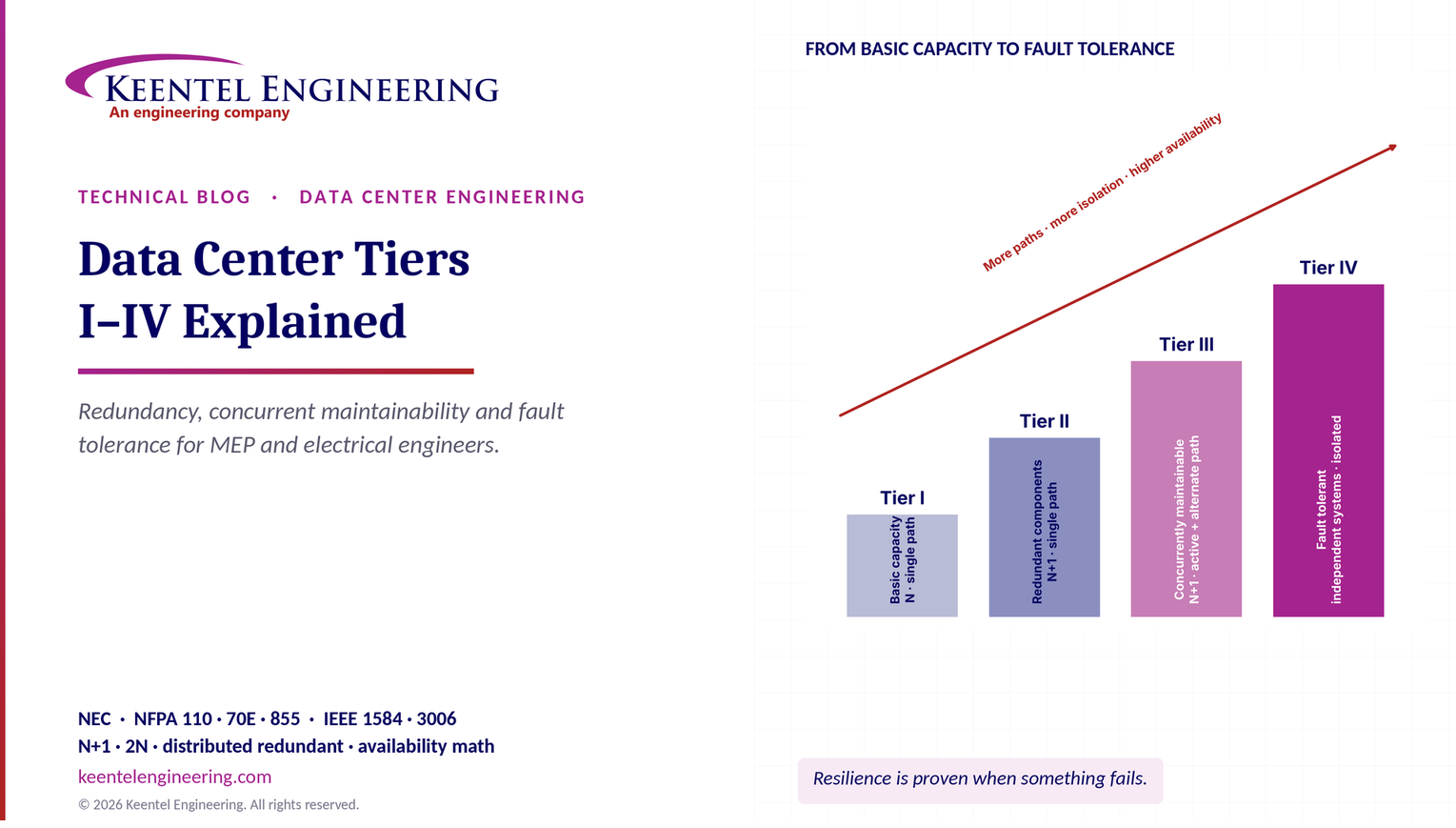
1. The step from Tier II to Tier III is about the path, not the equipment. It is the second distribution path and the maintainability of everything on it that delivers concurrent maintainability.
2. The step from Tier III to Tier IV is about failure and its consequences. Fault tolerance, compartmentalization and continuous cooling are the additions; the capacity count can stay similar.
3. Redundancy has diminishing returns unless common-cause failures are removed. In Worked Example 4, two independent paths cut expected unavailability from about 200 minutes a year to under 0.1 minute in theory, but a 5% common-cause share brings it back to about 10 minutes.
4. Utilization drives cost. A 2N UPS system can never be loaded above 50%; 3-to-make-2 distributed redundancy allows about 67%; 4-to-make-3 about 75%. The difference is millions of dollars of equipment at 10 MW and above.
5. The generator plant is the Tier's power source. Generator rating type, fuel storage (a commonly cited minimum of 12 hours on site), fuel delivery paths and paralleling controls must meet the same Tier logic as the UPS.
6. Controls are the most frequently missed single point of failure. One PLC, one DC control power panel or one network switch can defeat an otherwise maintainable topology.
7. US code compliance and Tier objectives are separate obligations. The NEC and NFPA standards are mandatory; the Tier is a performance objective that sits on top. Neither replaces the other.
8. The Tier is proven in commissioning and kept in operations. Integrated systems testing proves the topology; operational practice and human factors decide whether it holds over 20 years.
Key terms
| Term | Meaning |
|---|---|
| N | The capacity needed to carry the design critical load, with no spare. |
| N+1 | N plus one redundant capacity component of the same type. |
| 2N | Two complete, independent systems, each able to carry the full design load. |
| 2(N+1) | Two independent systems, each with its own redundant component. Often written 2N+2 in specifications; sometimes loosely called 2N+1. |
| Distributed redundant | Three or more systems, each loaded below its rating, so that the loss of any one leaves the others able to carry the load (for example, 3-to-make-2 or 4-to-make-3). |
| Block redundant / catcher | Several primary systems backed by a shared reserve system that "catches" the load of a failed system through static or automatic transfer switches. |
| Capacity component | Equipment that provides capacity: UPS module, generator, chiller, pump, cooling unit, cooling tower, fuel pump. |
| Distribution path | The route that delivers power or cooling to the critical load: switchgear, buses, breakers, transfer switches, cables, pipes, valves. |
| Concurrent maintainability | Every capacity component and distribution element can be removed from service on a planned basis without affecting the critical load. |
| Fault tolerance | A single unplanned failure or event, and its consequences, does not affect the critical load. |
| Compartmentalization | Physical separation of redundant systems and paths so that one event cannot affect both. |
| Continuous cooling | Uninterrupted heat removal from the critical space through a utility failure and generator start sequence. |
| Single point of failure (SPOF) | Any element whose failure alone interrupts the critical load. |
| Availability (A) | The fraction of time a system is able to perform its function, commonly A = MTBF / (MTBF + MTTR). |

Part B — Data Center Tiers I to IV: What They Mean for MEP and Electrical Engineers
How each Tier objective translates into power, cooling, fuel, controls and fire protection design; how to size the equipment and quantify what redundancy buys; and how to prove the result in commissioning, using US codes and standards.
1. Where the Tiers come from, and who decides
The Tier classification system was developed by the Uptime Institute in the 1990s to give owners, designers and operators a common language for data center site resilience. Today it is published as the Tier Standard: Topology, which defines the four Tier objectives, and the Tier Standard: Operational Sustainability, which covers how a facility is staffed, maintained and managed. "Tier" and "Tier Certification" are Uptime Institute terms, and only the Uptime Institute certifies facilities against them.
Certification has three distinct steps, and owners often confuse them:
| Certification | What is assessed | When it happens | What it proves |
|---|---|---|---|
| Tier Certification of Design Documents (TCDD) | Drawings and specifications | Before construction documents are complete | The design, on paper, meets the Tier objective |
| Tier Certification of Constructed Facility (TCCF) | The built facility, through on-site demonstrations | After construction and commissioning | The facility, as built, performs to the Tier objective under maintenance and failure scenarios |
| Operational Sustainability | Staffing, maintenance, training, procedures, planning | During operation | The facility is operated in a way that preserves its Tier performance |
A design certification does not certify the building. Many facilities are marketed as "Tier III design" without ever demonstrating the constructed facility. Owners and tenants who depend on the Tier should ask which certification applies.
ANSI/TIA-942-C (2024) is the Telecommunications Industry Association's data center infrastructure standard. It defines Rated-1 to Rated-4 levels across telecommunications cabling, architectural, electrical and mechanical systems. The levels are conceptually close to Tiers I to IV, but the requirements and the assessment model differ, and conformity can be self-assessed or assessed by third-party bodies.
ANSI/BICSI 002 is the BICSI design and implementation best-practices standard. It describes availability Classes F0 to F4, where F0 is a single-path facility without a generator and F4 approximates fault tolerance. It is a design guide rather than a certification scheme, and it is particularly useful for its detailed electrical, mechanical and cabling guidance.
| Objective | Uptime Institute | ANSI/TIA-942-C | ANSI/BICSI 002 |
|---|---|---|---|
| Basic capacity | Tier I | Rated-1 | Class F1 (F0 below it) |
| Redundant components | Tier II | Rated-2 | Class F2 |
| Concurrently maintainable | Tier III | Rated-3 | Class F3 |
| Fault tolerant | Tier IV | Rated-4 | Class F4 |
The alignment is conceptual. A facility that meets TIA-942 Rated-3 should be described as Rated-3, not as Tier III; a facility designed to Tier III objectives but not certified should be described as "designed to Tier III objectives". Precise language avoids contractual disputes with tenants and lenders.
The modern Tier Standard is performance based. It states objectives (concurrent maintainability, fault tolerance) and tests the design and the facility against them. It does not prescribe a particular one-line diagram, equipment brand or redundancy notation. Two designs with completely different architectures can both meet Tier III, and a design that looks "2N" on a sketch can fail Tier IV because of a shared control system. The engineer's job is to demonstrate the objective, component by component and path by path, not to pick a notation.
How Keentel Engineering helps here: Keentel helps owners choose the right framework and the right objective before design begins. We prepare a Tier basis-of-design document that states the objective for each system (electrical, mechanical, fuel, controls, fire protection), the redundancy philosophy, the operating modes that must be supported and the codes that apply, so every discipline designs to the same target and the certification reviewer sees a coherent intent.
2. Redundancy notation and what it really costs
Redundancy is always stated relative to N, the capacity needed to carry the design critical load. The notation is simple; its consequences for equipment count, loading and efficiency are not.
| Configuration | Systems | Each system rated for | Maximum normal loading | Loading after one system fails | Tolerates |
|---|---|---|---|---|---|
| N | 1 | 100% of load | 100% | Outage | Nothing |
| N+1 | 1 (with a spare module) | 100% + one module | N/(N+1) | 100% of N modules | One module failure; not a bus or path failure |
| 2N | 2 | 100% of load | 50% | 100% | Loss of a complete system or path |
| 2(N+1) | 2 (each with a spare) | 100% + one module | Below 50% | Below 100% | Loss of a system plus a module in the surviving system |
| 3-to-make-2 (distributed redundant) | 3 | 50% of load | 66.7% | 100% | Loss of any one system |
| 4-to-make-3 (distributed redundant) | 4 | 33.3% of load | 75% | 100% | Loss of any one system |
| Block redundant (catcher) | n primaries + 1 reserve | Each primary carries its block; the reserve matches the largest block | Primaries up to 100% of their rating | Reserve picks up one failed block | Loss of any one primary system |
The maximum loading in normal operation follows from the requirement that the surviving systems must carry the full load after one fails. For a distributed redundant design with n systems, each rated S, carrying load P:

That gives the familiar limits: 50% for 2N (n = 2), 66.7% for 3-to-make-2 and 75% for 4-to-make-3. In practice designers keep a margin below these limits for load growth, measurement error and imbalance between systems.
Given. Critical IT load 10 MW at unity power factor (modern UPS modules are rated in kW at power factor 1.0). UPS modules of 1,250 kW. Compare N+1, 2N, 2(N+1), 3-to-make-2 and 4-to-make-3.
N. 10,000 ÷ 1,250 = 8 modules.
| Configuration | Modules | Installed UPS capacity | Normal loading per system | Loading after worst single failure |
|---|---|---|---|---|
| N+1 (one system) | 9 | 11,250 kW | 10,000 ÷ 11,250 = 88.9% | 100% (8 modules) |
| 2N | 2 × 8 = 16 | 20,000 kW | 5,000 ÷ 10,000 = 50.0% | 100% |
| 2(N+1) | 2 × 9 = 18 | 22,500 kW | 5,000 ÷ 11,250 = 44.4% | 88.9% |
| 3-to-make-2 | 3 × 4 = 12 | 15,000 kW | 3,333 ÷ 5,000 = 66.7% | 100% |
| 4-to-make-3 | 4 × 3 = 12 | 15,000 kW | 2,500 ÷ 3,750 = 66.7% | 3,333 ÷ 3,750 = 88.9% |
Observations.
- 2N needs 16 modules; either distributed redundant design needs 12, a saving of four 1,250 kW modules and their batteries, switchgear, space and cooling. At an illustrative installed cost of about $450 per kW of UPS capacity, that is roughly $9.0 million for 2N against $6.8 million for 3-to-make-2.
- With discrete module sizes, 4-to-make-3 does not save modules here: 3.33 MW per system rounds up to three 1,250 kW modules. Module size should be chosen together with the architecture.
- N+1 is the cheapest, but it protects only against a module failure. The UPS output switchboard and everything downstream remain single points of failure. That is Tier II territory unless a second distribution path is added.
- The normal loading of 2N systems (50% or less) puts UPS modules in the lower part of their efficiency curve. Modern double-conversion modules are efficient across a wide range, and many offer high-efficiency or multi-mode operation, but the loss difference is still worth calculating over a 15 to 20 year life.
How Keentel Engineering helps here: Keentel compares redundancy architectures on equal terms: equipment counts, installed capacity, utilization, efficiency at expected loading, footprint, failure scenarios, maintainability and life-cycle cost. We recommend module sizes and system groupings together, because a good architecture with the wrong module size can lose most of its advantage.
3. Tier I: basic capacity
A Tier I facility has dedicated space for IT equipment, a UPS to ride through power sags, spikes and short interruptions, dedicated cooling equipment that runs outside office hours, and an engine generator to carry the load through extended utility outages. It has no redundant capacity components and a single, non-redundant distribution path.
Electrical. Typically a single utility service (often 13.8 kV, 12.47 kV or 480 V depending on size), one generator, an automatic transfer switch (ATS), one UPS system and one distribution path through switchboards, PDUs and remote power panels to the racks. Any planned work on the generator, ATS, switchboard, UPS or distribution requires an IT shutdown, and any failure of them causes one.
Mechanical. N cooling units or chillers, single piping and controls.
What Tier I is not. It is not "no protection". It is a real data center infrastructure with a UPS, generator and dedicated cooling, designed for a business that can schedule downtime. Server rooms in office buildings often fail even Tier I because they lack a generator or dedicated cooling.
Where it fits. Test and development environments, small businesses with tolerant workloads, and edge sites where the application is replicated elsewhere.
How Keentel Engineering helps here: For smaller facilities and edge sites, Keentel delivers right-sized electrical designs that meet the NEC, NFPA 110 and NFPA 75 cleanly at minimum cost, with a clear upgrade path (spaces, conduits, switchgear sections and tie provisions) so the owner can move to a higher objective later without tearing out what was built.
4. Tier II: redundant capacity components
Tier II adds redundant capacity components: N+1 UPS modules, engine generators, chillers, pumps, cooling units and similar equipment. The distribution path remains single.
Electrical. Generators paralleled on a common bus with one spare unit; UPS modules in an N+1 parallel system; but one generator paralleling switchboard, one main switchboard, one UPS input and output board, and one set of PDUs. A failed UPS module or generator no longer drops the load, and individual modules can be serviced. But work on any bus, breaker, static switch, cable or panel in the path still means an IT shutdown, and a fault on any of them still causes an outage.
Mechanical. N+1 chillers, pumps and cooling units on a single piping system with single valves and headers.
The hidden trap. Tier II designs often look impressive on an equipment schedule. The weakness is the path. A UPS output switchboard bus fault, a failed paralleling controller or a cracked chilled-water header takes everything down regardless of how many spare modules exist.
Where it fits. Small and medium enterprises and regional facilities where a few planned maintenance windows a year are acceptable.
How Keentel Engineering helps here: Keentel's single-point-of-failure review of Tier II facilities identifies which path elements carry the most risk and which inexpensive changes (bypass provisions, a tie breaker, a second static switch, a temporary-generator connection, a looped header) remove the largest share of outage exposure without a full Tier upgrade.
5. Tier III: concurrently maintainable
Tier III is the most widely specified objective for enterprise, colocation and cloud facilities, because it removes the large majority of planned downtime at a moderate cost premium. The requirement is easy to state and hard to deliver: every capacity component and every element of every distribution path can be removed from service on a planned basis without affecting the critical load.
Engineers tend to check the obvious items (UPS modules, generators, chillers) and miss the rest. A Tier III review must cover, at minimum:
| System | Items that must be concurrently maintainable |
|---|---|
| Medium-voltage power | Utility switchgear and generator switchgear buses, breakers, ties, protective relays and their DC control power, potential transformers, cable sections, MV/LV transformers |
| Generator plant | Each generator, its starting batteries and chargers, paralleling switchgear buses and breakers, master controls, load-shed and load-add logic, radiators and ventilation |
| Fuel | Bulk tanks, transfer pumps, filters, polishing systems, day tanks, supply and return piping, valves, level controls |
| Low-voltage power | Switchboards, buses, main and tie breakers, ATS or closed-transition transfer schemes, static transfer switches, UPS input and output boards, maintenance bypasses, PDUs, remote power panels, busway |
| UPS and storage | UPS modules and systems, battery strings or cabinets, battery breakers, battery monitoring, static bypass |
| Mechanical | Chillers, cooling towers, dry coolers, pumps, heat exchangers, CRAH/CRAC units, coolant distribution units (CDUs), headers, piping sections, valves, makeup water, water treatment |
| Controls | BMS, EPMS, generator and switchgear PLCs, network switches, control power supplies, sensors that drive automatic actions |
| Ancillary | Fire protection interfaces that trip equipment, emergency power off (EPO) circuits, ventilation for battery and generator rooms |
- Two distribution paths to the critical load. One active and one alternate is the minimum. Most modern designs use two active paths, A and B, feeding dual-corded IT equipment.
- Single-corded loads. Each needs a point-of-use or rack-mounted automatic transfer switch, or a static transfer switch upstream, so it can be fed from either path. Without one, every single-corded load is a concurrent maintainability failure.
- Maintainable switchgear. Main-tie-main or double-ended substations; isolation devices on both sides of every component; maintenance bypasses for each UPS system; and the ability to move load between sources by closed transition or by a planned, brief transfer the IT load can ride through.
- Isolation points. Every component must be isolatable without de-energizing the alternate path. A breaker that cannot be racked out without opening a shared bus is a classic failure.
- Control power. Separate DC control power for A-side and B-side switchgear, or a maintainable arrangement, and redundant PLCs for generator paralleling and transfer logic.
- Generator plant. N+1 generators with a paralleling bus that can be maintained in sections, or generators assigned to independent paths.
Concurrent maintainability protects planned work. It does not require the facility to survive an unplanned failure while one path is out of service, nor a failure whose consequences (fire, smoke, water) affect both paths at one location. In a Tier III facility running on a single path during maintenance, any failure on the remaining path can cause an outage. That exposure is managed by limiting maintenance windows, scheduling work carefully and, often, adding features from Tier IV practice where risk justifies them.
Keentel uses a structured, component-by-component method:
1. List every component on the one-line diagrams, mechanical flow diagrams, fuel diagrams and controls architecture, including isolation devices and control power.
2. For each component, write the maintenance scenario: what is isolated, which devices are opened, where the load goes, which protective settings change, and which control functions are affected.
3. Check capacity in the scenario: the surviving equipment must carry the full design load at design ambient conditions.
4. Check the alternate path: every element of the path that carries the load in that scenario must be available.
5. Check controls and monitoring: automatic functions still needed during maintenance must still work.
6. Record gaps and fixes, then re-run the scenarios affected by each fix.
The output is a scenario matrix that becomes the basis for methods of procedure (MOPs) and for integrated systems test scripts.
How Keentel Engineering helps here: Keentel performs concurrent maintainability reviews at schematic, design development and construction document stages, across electrical, mechanical, fuel, controls and fire protection interfaces. Typical findings include shared DC control panels, single fuel headers, unisolatable chilled-water valves, single paralleling PLCs and single-corded loads without transfer switches, all of which are cheap to fix on paper and expensive after construction.
6. Tier IV: fault tolerant
Tier IV requires that any single unplanned failure of a capacity component or distribution element, or any single event, does not affect the critical load. It builds on Tier III with three explicit additions.
The facility must have multiple independent systems so that, after the loss of any one system, the remaining capacity still carries the design load. The facility must also detect the failure and respond automatically, isolating it and keeping the load supported without depending on operator action. In electrical terms that means independent A and B systems (or a distributed redundant set) from the generator plant to the IT input, with no shared bus, controller, control power source or network whose failure takes down both.
Redundant systems and their distribution paths must be physically separated so that a single event, such as a fire, arc flash, explosion, smoke release or water leak, cannot affect both. Typical measures:
- Separate electrical rooms for A and B switchgear, UPS and batteries, with rated fire separations.
- Separate cable and pipe routes, including where they enter the data hall; a shared corridor or tray is a classic compartmentalization failure.
- Separate generator enclosures or yards, fuel systems and day tanks.
- Separate mechanical plant sections and piping routes.
Cooling must continue without interruption through a utility failure and the generator start and transfer sequence. Air-cooled IT equipment heats the room quickly when fans and chillers stop, and liquid-cooled processors have even less thermal margin. Continuous cooling is usually delivered by UPS-backed CRAH or fan wall units and pumps, chilled-water thermal storage, UPS-backed CDUs for liquid cooling, or a combination.
Given. A 10,000 sq ft data hall with a 15 ft clear height and 2 MW of IT load. The air in the room is about 150,000 cu ft. Air's volumetric heat capacity is roughly 0.018 BTU per cubic foot per °F.
Air heat capacity. 150,000 × 0.018 ≈ 2,700 BTU/°F.
Heat release. 2,000 kW × 3,412 BTU/kWh ÷ 60 ≈ 113,700 BTU per minute.
Air-only temperature rise rate. 113,700 ÷ 2,700 ≈ 42 °F per minute.
The building structure, raised floor, racks and IT hardware absorb heat too, so measured rises are much slower than this air-only figure. But the order of magnitude explains why cooling interruptions of one to three minutes during a chiller restart can push inlet temperatures beyond the ASHRAE allowable range in high-density rooms. Chiller restart after a power interruption can take several minutes unless the chillers have fast-restart capability.
Thermal storage sizing. To carry 3,061 tons of cooling (Worked Example 7) for 10 minutes from a chilled-water tank with a 12 °F usable temperature difference:

V ≈ 3,061 × 12,000 × (10 ÷ 60) ÷ (8.34 × 12) ≈ 61,000 gallons, before allowances for stratification and tank efficiency. The pumps and air handlers that move that water must themselves be on UPS power.
- A single EPMS or BMS network ring whose failure causes both generator plants to lose their load-add logic.
- A and B cables that share a tray or a penetration for a few feet.
- A shared chilled-water header or a single makeup-water connection.
- Fire suppression release on one side that trips equipment on both sides through a common EPO circuit.
- A and B UPS systems synchronized through a shared load bus synchronization controller with no independent fallback.
How Keentel Engineering helps here: Keentel performs fault tolerance reviews that go beyond the one-line diagram: failure-mode and consequence analysis for each component, compartmentalization walk-downs on 3D models and in the field, control system dependency mapping, and automatic response checks. We confirm that every single failure is detected, isolated and ridden through without operator action.
7. The power source: engine generators as the Tier's foundation
The Tier Standard treats the on-site engine generator plant as the facility's reliable source of power. Utility power is valuable and is usually the cheapest source, but it is outside the owner's control, so it does not count towards the Tier objective. A Tier III facility with two utility feeds and an undersized generator plant is not Tier III; a facility with one utility feed and a properly redundant, maintainable generator plant can be.
Generator sets are rated by the manufacturer under ISO 8528-1 duty classes. The commonly used US terms map approximately as follows:
| Rating | Typical meaning | Tier implication |
|---|---|---|
| Emergency standby power (ESP) | Variable load during a utility outage, with annual run-hour limits (often around 200 hours) and a limited average load factor | Not acceptable on its own for Tier III or IV where it carries runtime limits |
| Limited-time running power (LTP) | Constant load for a limited number of hours per year | Generally not suitable as the Tier basis |
| Prime power (PRP) | Variable load for unlimited hours, with an average load factor limit (commonly 70%) and some overload capability | Acceptable when applied within its limits, often by derating |
| Continuous operating power (COP) | Constant load for unlimited hours | Acceptable |
| Data center continuous power (DCC) | A manufacturer rating for unlimited hours at varying data center load, defined by each manufacturer | Accepted where the manufacturer's rating carries no runtime limit |
The principle behind the Tier Standard's position is straightforward: in a long utility outage the generators are the facility's only source, so their rating must allow unlimited running at the design load. Engineers should confirm the rating basis in writing with the manufacturer and state it in the specification.
- NEC Article 700 (emergency systems), 701 (legally required standby) and 702 (optional standby) classify generator-supplied loads. Life-safety loads (egress lighting, fire alarm, some smoke control) are typically Article 700; the IT load is normally Article 702 optional standby. Each class has its own transfer time, separation and selective coordination rules.
- NEC Article 708 (critical operations power systems, COPS) applies only where a government authority designates a facility as critical to public safety or national security. It imposes risk assessment, physical security, commissioning and selective coordination requirements. It is not automatic for commercial data centers.
- NFPA 110 governs emergency and standby power system installation, performance, maintenance and testing. It classifies systems by Type (maximum time to restore power, for example Type 10 = 10 seconds), Class (minimum running time without refueling, for example Class 48 = 48 hours) and Level (Level 1 where failure could cause loss of life or serious injury; Level 2 otherwise).
- NFPA 111 covers stored electrical energy emergency and standby power systems, relevant where batteries or other stored energy act as the emergency source.
Given. 10 MW critical IT load. UPS efficiency 96%. Battery recharge allowance 10% of IT load. Mechanical load on the design day 3,000 kW. Other house loads 300 kW. Generators rated 2,500 kW (3,125 kVA at 0.8 power factor) on a data center continuous basis, derated 3% for altitude and 4% for intake air temperature at the site per the manufacturer's curves.
Generator load.
| Load | kW |
|---|---|
| UPS input at full IT load: 10,000 ÷ 0.96 | 10,417 |
| Battery recharge allowance | 1,000 |
| Mechanical plant, design day | 3,000 |
| House and ancillary loads | 300 |
| Total | 14,717 |
Effective unit rating. 2,500 × 0.97 × 0.96 ≈ 2,328 kW.
Unit count. 14,717 ÷ 2,328 = 6.3, so N = 7 and N+1 = 8 units. With all eight running, each carries 14,717 ÷ (8 × 2,328) ≈ 79% of its derated rating.
Checks the count alone does not cover.
- Step loading. The UPS rectifiers walk in their load gradually, but mechanical loads restart in blocks. Each generator typically accepts a first load step of a fraction of its rating (often on the order of 25% to 50%, engine dependent) with acceptable frequency and voltage dips. A 25% step on a 2,328 kW unit is about 580 kW. Load-add sequencing must be designed accordingly.
- UPS interaction. Rectifier input filters, walk-in rates and generator voltage regulator response must be coordinated so the UPS accepts the generator source without repeated transfers to battery.
- Paralleling bus and controls. For Tier III, the paralleling switchgear must be maintainable in sections; for Tier IV, a single bus or master controller failure must not disable the plant.
- Where N is counted. If generators are assigned to A and B paths in a 2N arrangement, each side needs N units (plus spares as required), which roughly doubles the plant. Many Tier IV designs use N+1 or N+2 generator plants with fault-tolerant paralleling instead.
How Keentel Engineering helps here: Keentel sizes generator plants from first principles (load profiles, step loading, motor starting, UPS walk-in, altitude and temperature derating) and designs the paralleling switchgear, load-add and load-shed logic, and protection so that the plant meets the Tier objective in every operating mode. We review the manufacturer's rating basis and transient performance data, and we model generator and UPS interaction where rapid load swings are expected.
8. Availability mathematics: what redundancy actually buys
The availability percentages quoted for each Tier are legacy figures from early observational studies. They are not part of the current Tier Standard. For reference, the arithmetic behind the usual quotes is:

| Legacy figure | Availability | Annual downtime |
|---|---|---|
| Tier I | 99.671% | (1 − 0.99671) × 8,760 ≈ 28.8 h |
| Tier II | 99.741% | ≈ 22.7 h |
| Tier III | 99.982% | ≈ 1.6 h (about 95 min) |
| Tier IV | 99.995% | ≈ 0.44 h (about 26 min) |
Some sources quote 22 hours for Tier II; the arithmetic gives 22.7 hours. Either way, these figures are not design targets. A project-specific availability analysis is much more useful, because it compares real design options with real component data.
Availability of a repairable component from its mean time between failures (MTBF) and mean time to repair (MTTR):

Components in series (every one must work):

Independent redundant paths in parallel (any one is enough):

k-out-of-n identical modules (at least k of n must work), as in an N+1 UPS system:

A common-cause (beta-factor) model, where a fraction β of each path's unavailability U is shared by both paths:

Given. Illustrative MTBF and MTTR values for a five-element distribution path. Real studies use IEEE 3006.8 and 3006.9 data, manufacturer data and the owner's own records.
| Component | MTBF (h) | MTTR (h) | Availability |
|---|---|---|---|
| Utility service and MV switchgear | 200,000 | 8 | 0.9999600 |
| MV/LV transformer | 300,000 | 72 | 0.9997601 |
| LV switchboard | 250,000 | 8 | 0.9999680 |
| UPS system | 100,000 | 6 | 0.9999400 |
| PDU | 500,000 | 4 | 0.9999920 |
Single path (series). The product is 0.9996201, an expected unavailability of about 3.3 hours (about 200 minutes) a year. The transformer dominates because of its long repair time, which is why on-site spares and maintenance bypasses matter as much as redundancy.
N+1 at module level. For UPS modules with A = 0.99952 (MTBF 50,000 h, MTTR 24 h), eight modules needed:
| Configuration | Availability of module group | Expected unavailability |
|---|---|---|
| 8 of 8 (N) | 0.99617 | about 2,014 min/yr |
| 8 of 9 (N+1) | 0.9999917 | about 4.3 min/yr |
| 8 of 10 (N+2) | 0.99999999 | about 0.007 min/yr |
N+1 makes the module group very reliable. It does nothing for the bus, static switch and output board those modules share.
Two independent paths. Ideal parallel combination of two such paths: 1 − (0.0003799)² ≈ 0.99999986, about 0.08 minutes a year.
With 5% common cause. U_sys ≈ (0.95 × 0.0003799)² + 0.05 × 0.0003799 ≈ 1.91 × 10⁻⁵, about 10 minutes a year, more than a hundred times the ideal figure.

Lessons.
1. Redundancy at the component level does not fix path weaknesses.
2. Independent paths are extremely effective in theory; common-cause failures decide the real result. This is the quantitative reason for compartmentalization, independent controls and disciplined operations in Tier IV.
3. Repair time matters. Spares strategy, maintenance bypasses and vendor response time are availability levers as powerful as extra equipment.
Standards. IEEE 3006.5 (probability methods), 3006.7 (reliability of 7×24 continuous power systems), 3006.8 (analyzing the reliability of power distribution systems) and 3006.9 (collecting data for reliability analysis) replace the legacy IEEE 493 (Gold Book), which remains a useful source of historical component data. Fault-tree analysis, reliability block diagrams and Monte Carlo simulation are the usual tools for full facilities.
How Keentel Engineering helps here: Keentel builds reliability block diagram and fault-tree models of competing architectures using IEEE 3006 methods, owner data and manufacturer data, including common-cause and repair-time sensitivity. The output is a defensible comparison of expected outage frequency and duration per architecture, which owners can weigh against capital and operating cost.
9. UPS systems and energy storage
The UPS is the bridge between a utility disturbance and the generator plant, and the last line of power conditioning before the IT load. Tier design affects the UPS in three ways: the redundancy architecture (Section 2), the ride-through energy, and the maintainability and isolation of every UPS element.
| UPS arrangement | Notes for Tier design |
|---|---|
| Double-conversion (online) modules in N+1 parallel systems | The workhorse of Tier II and Tier III; requires maintenance bypass and isolation for each module and the system |
| 2N systems with static transfer switches (STS) for single-corded loads | Common Tier IV pattern; the STS itself must be maintainable and its failure modes analyzed |
| Distributed redundant (3-to-make-2, 4-to-make-3) | Higher utilization; needs careful load assignment so no single system loss overloads the others |
| Block redundant (catcher) | A reserve system catches a failed primary through transfer switches; transfer reliability and controls independence are critical |
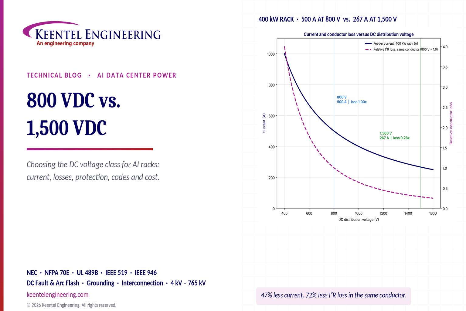
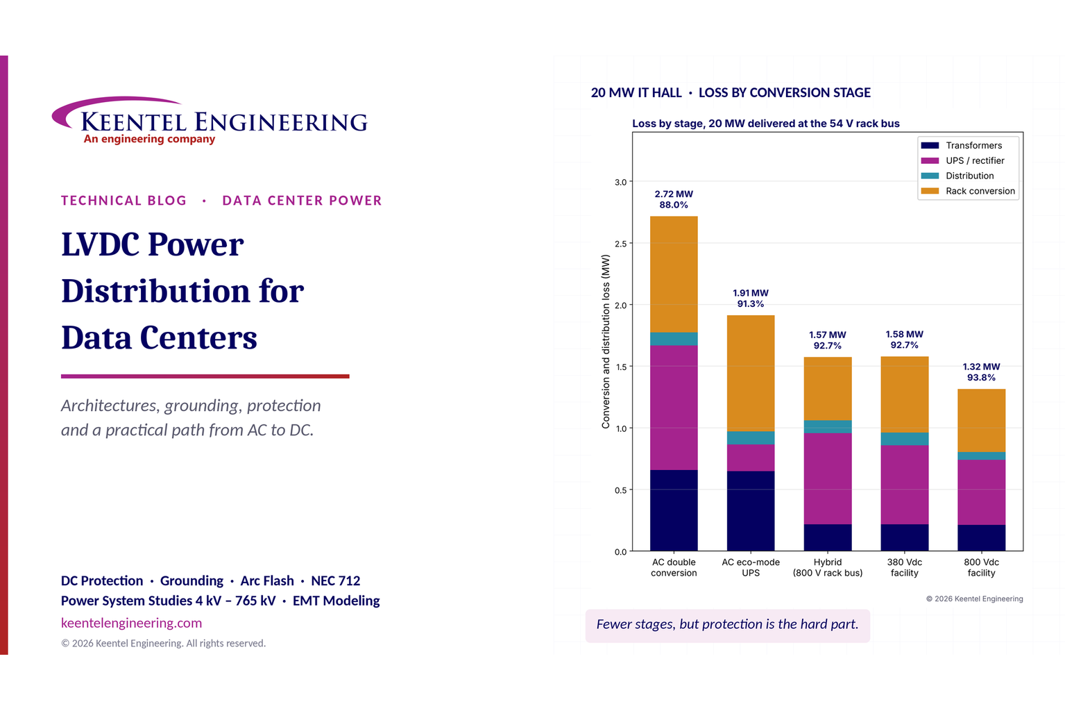
| Rack-level or row-level battery backup with 48 VDC or 800 VDC distribution | Emerging in hyperscale and AI designs; Tier analysis must address the shared upstream paths and battery shelf maintainability |
UPS equipment in the US is listed to UL 1778. Lithium-ion battery systems for UPS service are typically evaluated with UL 1973(batteries) and, for energy storage systems, UL 9540 with UL 9540A fire-propagation test data. NFPA 855 governs the installation of stationary energy storage systems above threshold quantities, including separation, ventilation, explosion control and fire protection, and the NEC (Articles 480 and 706) covers battery and energy storage system wiring.
Given. 10 MW IT load per UPS side (a 2N design means each side must carry the full load alone). Required ride-through 5 minutes at end of life. Inverter (DC to AC) efficiency 96%. Aging factor 1.25 (battery sized so 80% end-of-life capacity still meets the load). Temperature factor 1.11 for operation below the rated temperature. Design margin 1.10.
DC energy at beginning of life.

E = 10,000 × (5 ÷ 60) ÷ 0.96 ≈ 868 kWh; × 1.25 ≈ 1,085 kWh; × 1.11 ≈ 1,204 kWh; × 1.10 ≈ 1,325 kWh per side.
Observations.
- A 2N design needs about 1,325 kWh on each side, about 2,650 kWh in total, for a 5-minute runtime. That is a significant fire-code quantity; NFPA 855 thresholds and separation rules will apply.
- Battery current is large: a 1,250 kW module at an end-of-discharge DC voltage around 400 V draws roughly 1,250 ÷ 0.96 ÷ 400 ≈ 3,260 A, which drives DC breaker, busway and cable sizing and DC arc-flash assessment.
- Five minutes is a common design choice, not a Tier requirement. Shorter runtimes (1 to 3 minutes) are increasingly used with reliable generator plants; the decision should be based on generator start, synchronize and transfer times plus a margin for a failed start and retry.
How Keentel Engineering helps here: Keentel sizes UPS and battery systems for real duty cycles, including aging, temperature and generator retry scenarios, and coordinates battery room design with NFPA 855, UL 9540A data, NEC Articles 480 and 706, ventilation, hydrogen or off-gas detection where applicable, and DC short-circuit and arc-flash studies.
10. MV/LV switchgear and protection
Switchgear is where most concurrent maintainability and fault tolerance gaps hide, because buses, breakers, control power and protection are shared by design. US data centers typically take utility power at 13.8 kV, 34.5 kV or, for large campuses, at 69 kV to 345 kV through an on-site substation, then distribute at 13.8 kV or 34.5 kV to unit substations that step down to 480Y/277 V. IT distribution is at 480 V to UPS systems, then 480 V or 415Y/240 V to the racks; 415Y/240 V allows 240 V single-phase to IT power supplies with fewer transformation stages.
| Arrangement | Tier fit | Notes |
|---|---|---|
| Single-ended unit substation, single bus | Tier I and II | Any bus or main breaker work requires shutdown |
| Double-ended (main-tie-main) substation | Tier III building block | Each half can be isolated while the other carries load, if each transformer is sized for both halves or load is transferred to the alternate path |
| Separate A and B substations feeding A and B paths | Tier III and IV | Needs independent control power and protection on each side |
| Ring or loop MV distribution with sectionalizing | Tier III at MV level | Each section maintainable; protection must remain selective in all configurations |
| Isolated A and B MV systems in separate rooms | Tier IV | Compartmentalized; ties, if any, need careful fault-tolerance analysis |
Equipment is typically metal-clad MV switchgear to IEEE C37.20.2, metal-enclosed LV power circuit breaker switchgear to IEEE C37.20.1 and UL 1558, or switchboards to UL 891. MV metal-enclosed interrupter switchgear is covered by IEEE C37.20.3.
Given. A 13.8 kV to 480Y/277 V unit substation serving 2,000 kW of mixed UPS input and mechanical load at 0.95 power factor. Transformer impedance 5.75%. Utility short-circuit capacity at 13.8 kV 500 MVA. Motor contribution from about 500 kVA of running motors.
Load. 2,000 ÷ 0.95 ≈ 2,105 kVA. In a double-ended substation each transformer must carry both halves when the other is out, so select 2,500 kVA (with fans or a higher rating if the combined load is larger).
Full-load current at 480 V.

I_FL = 2,500,000 ÷ (1.732 × 480) ≈ 3,007 A.
Bolted three-phase fault at the 480 V bus. With an infinite source, I_SC ≈ 3,007 ÷ 0.0575 ≈ 52.3 kA. Including the 500 MVA source (Z_source ≈ 2,500 ÷ 500,000 = 0.005 pu on the transformer base), I_SC ≈ 3,007 ÷ (0.0575 + 0.005) ≈ 48.1 kA. Adding motor contribution of about four times motor full-load current (4 × 601 A ≈ 2.4 kA) gives roughly 50.5 kA.
What this means. The switchgear needs a short-circuit rating of at least 65 kA at 480 V (the next common rating above 50.5 kA), and the arc-flash incident energy at the bus can be high. Note that a main-tie-main substation operated with the tie closed doubles the available fault current, which is one reason most designs operate with the tie open and use interlocks or closed-transition logic with momentary paralleling only.
K-factor. For a UPS input spectrum with 20% fifth, 12% seventh, 6% eleventh and 4% thirteenth harmonic current (per unit of fundamental), the K-factor is:

K ≈ 3.2, so a K-4 rated transformer, or a standard transformer derated per IEEE C57.110, is appropriate. Modern active front-end UPS rectifiers have much lower harmonic content, which should be confirmed with manufacturer data and checked against IEEE 519 at the point of common coupling.
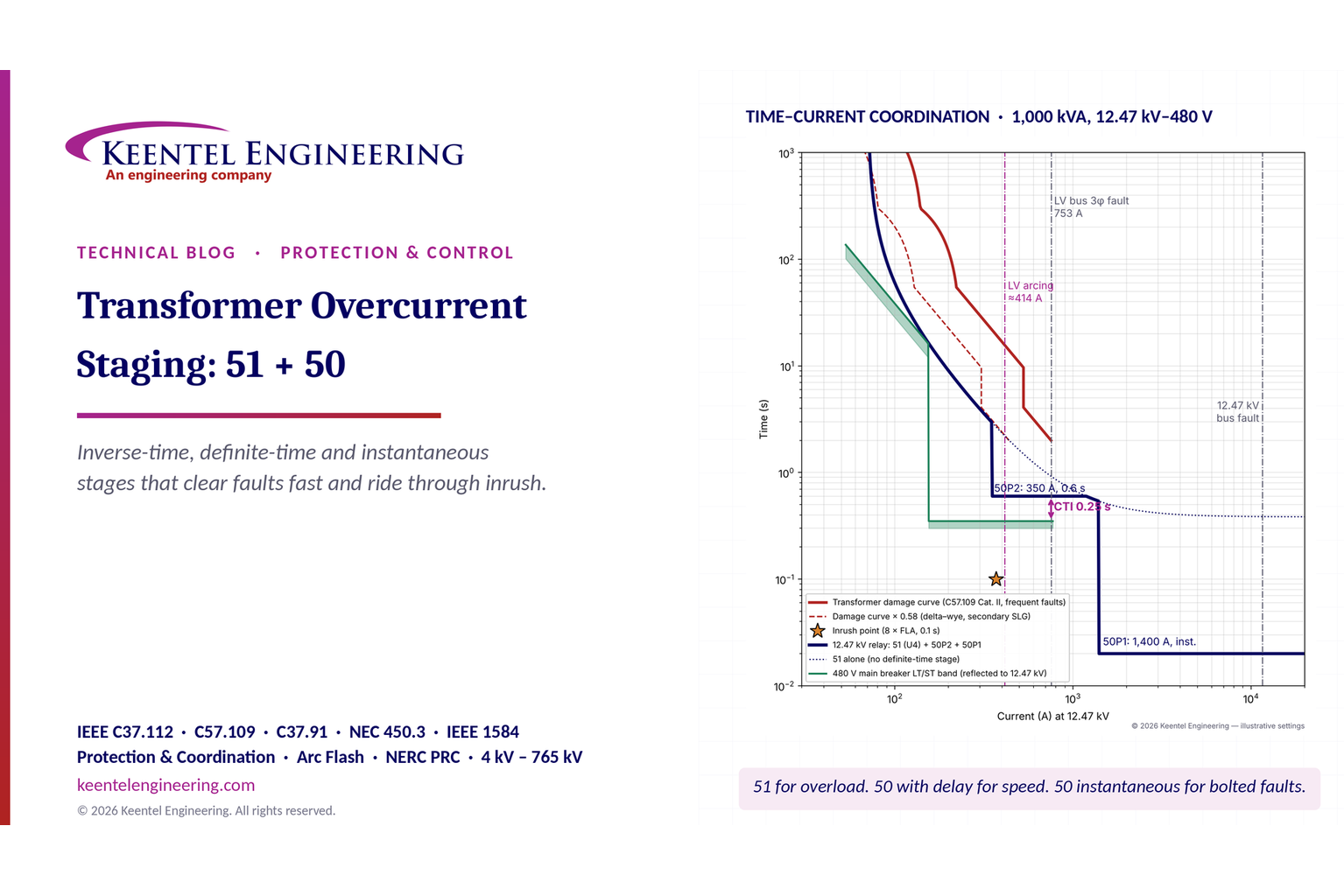
- Selective coordination. NEC 700.32, 701.32 and 708.54 require selective coordination for emergency, legally required standby and COPS systems. Optional standby IT systems do not have a code mandate, but Tier objectives make selectivity essential in practice: a breaker that trips upstream of a fault takes out more of the critical load than necessary.
- Ground-fault protection. NEC 230.95 requires ground-fault protection of equipment on solidly grounded wye services of more than 150 V to ground and 1,000 A or more; NEC 215.10 and 240.13 cover feeders and equipment. Multi-source 480 V systems with neutral connections need careful ground-fault sensing design to avoid nuisance tripping and blind spots, particularly when generators and transformers are paralleled.
- Arc energy reduction. NEC 240.87 requires an arc energy reduction method (such as zone-selective interlocking, differential relaying, an energy-reducing maintenance switch or active arc-flash mitigation) for circuit breakers rated or adjustable to 1,200 A or more.
- Arc-flash studies. IEEE 1584-2018 calculation methods and NFPA 70E labeling and work practices apply. Concurrent maintainability helps safety, because work can be done on de-energized equipment while the load runs on the alternate path, but only if isolation points are designed to allow it.
- Protection in all operating modes. Settings must be coordinated for normal, maintenance, generator-only and transfer configurations, including closed-transition paralleling.
How Keentel Engineering helps here: Keentel designs MV and LV distribution for data centers from 4 kV to 345 kV utility interconnections and performs short-circuit, protective device coordination and IEEE 1584 arc-flash studies for every operating mode. We specify switchgear arrangements, interlocks, maintenance-mode settings and arc energy reduction methods so concurrent maintainability and worker safety reinforce each other.
11. HVAC and precision cooling
Mechanical systems follow the same Tier logic as electrical systems: capacity components (chillers, cooling towers, dry coolers, pumps, CRAH or CRAC units, fan walls, CDUs) and distribution paths (piping, valves, headers, ductwork). Many facilities that pass an electrical review fail on the mechanical side, because a single valve or header section cannot be isolated.
ASHRAE TC 9.9 thermal guidelines define a recommended inlet air range of 18 °C to 27 °C (64.4 °F to 80.6 °F) for most IT equipment classes, with wider allowable ranges by class (A1 to A4) and a newer H1 class for high-density equipment with a narrower range. Designing to the upper part of the recommended range reduces chiller energy and increases economizer hours, but leaves less margin in a cooling interruption, which links directly to continuous cooling in Tier IV. ASHRAE Standard 90.4 sets energy-efficiency requirements specifically for data centers, using mechanical and electrical loss components rather than a single PUE target.
Given. 10 MW IT load, UPS losses at 96% efficiency (about 417 kW), electrical distribution losses about 2% of IT (200 kW), lighting and other heat 150 kW.
Heat load. 10,000 + 417 + 200 + 150 ≈ 10,767 kW.

Q ≈ 10,767 ÷ 3.517 ≈ 3,061 tons of refrigeration.
Chiller selection. With 1,000-ton chillers, N = 4 (4,000 tons, about 77% loaded) and N+1 = 5 for Tier II and III. For Tier IV, the arrangement must also survive the loss of a complete piping system or plant section, which typically means two independent chilled-water systems (A and B loops) each able to carry the load, or a looped, valved header with compartmentalized plant sections, plus continuous cooling.
Points beyond the count.
- Size for design-day ambient conditions at the site, not nominal ratings; air-cooled chillers lose capacity sharply in hot weather.
- Pumps, cooling towers, heat exchangers and makeup water need the same redundancy and maintainability as the chillers.
- Valves on headers must allow any section to be isolated while the rest of the system carries the load. Double block valves may be needed for safe maintenance.
- Controls must fail to a safe state: a failed controller should leave equipment running, not stopped.
High-density AI racks of 50 kW to over 100 kW typically use direct-to-chip liquid cooling with CDUs separating the facility water loop from the technology cooling loop. The CDU, its pumps, its controls and its power supply become critical Tier components. Concurrent maintainability needs redundant CDU pumps or redundant CDUs with isolation valves; fault tolerance needs CDUs fed from independent power and water paths with automatic switchover; continuous cooling needs CDU pumps on UPS power, because processor temperatures rise within seconds of losing coolant flow.
How Keentel Engineering helps here: Keentel's MEP team designs cooling plants and liquid-cooling distribution to the Tier objective, with the electrical feeds, controls power and UPS backing for pumps, fans and CDUs engineered together. Our concurrent maintainability reviews include every valve, header section, CDU and controller, because the mechanical side is where many design certifications fail.
12. Energy, efficiency and PUE
Higher Tiers carry more equipment at lower utilization, which affects efficiency. Power usage effectiveness (PUE) is the industry's common efficiency metric:

Given. IT 10,000 kW; UPS losses 417 kW; distribution losses 200 kW; cooling at an average of 0.8 kW per ton on about 2,500 tons average load (2,000 kW); lighting and other 150 kW.
Facility load. 10,000 + 417 + 200 + 2,000 + 150 ≈ 12,767 kW.
PUE. 12,767 ÷ 10,000 ≈ 1.28. Annual facility energy ≈ 12.767 MW × 8,760 h ≈ 111,800 MWh.
Sensitivity. If a 2N design runs UPS modules at 25% to 35% load where efficiency is one or two points lower than at 70%, UPS losses may rise by 100 to 200 kW, changing PUE by about 0.01 to 0.02 and costing hundreds of thousands of dollars a year at typical industrial energy rates. High-efficiency operating modes, right-sized modules and distributed redundant architectures reduce the penalty. The correct comparison uses the manufacturer's efficiency curves at the loading each architecture actually experiences.
How Keentel Engineering helps here: Keentel calculates PUE and annual energy for each architecture under expected load growth, using real UPS, transformer and cooling efficiency curves, and supports ASHRAE 90.4 compliance documentation. Owners see the true life-cycle cost of each Tier option, not just the capital cost.
13. Fuel systems
Fuel is part of the Tier topology. A redundant generator plant fed through a single pump, filter or header is no better than that single element.
Storage. The Tier Standard sets a minimum on-site fuel storage at design load (commonly cited as 12 hours) as the baseline for all Tiers. NFPA 110 Class defines the minimum running time without refueling for emergency and standby systems, and local codes, insurers and owner policies often require more. Many US enterprise and colocation facilities store 24 to 72 hours; mission-critical sites in hurricane- or wildfire-prone regions often store 96 hours or more and hold priority fuel delivery contracts.
Given. Generator load 14,717 kW (Worked Example 3). Diesel fuel consumption at high load about 0.068 gallons per kWh (about 14.7 kWh per gallon); confirm with the manufacturer's fuel curves.

| Runtime | Fuel required |
|---|---|
| 12 h | ≈ 12,000 gal |
| 24 h | ≈ 24,000 gal |
| 48 h | ≈ 48,000 gal |
| 72 h | ≈ 72,000 gal |
| 96 h | ≈ 96,000 gal |
Add unusable tank volume, allowances for fuel quality and testing, and the fuel burned during monthly and annual tests. Diesel stored for long periods also needs a fuel polishing and quality program to remain usable.
Maintainability and fault tolerance. For Tier III, bulk tanks, transfer pumps, filters, day tanks and piping must be maintainable without stopping fuel to running generators, which usually means multiple tanks, duplex pumps and filters, looped or dual supply headers and isolation valves. For Tier IV, a single failure (a pump, a leak, a level control) must not interrupt fuel to the generators needed to carry the load, and fuel routes should be compartmentalized. NFPA 30 and NFPA 37 govern flammable liquid storage and engine installation; EPA spill prevention (SPCC) rules apply above threshold quantities.
How Keentel Engineering helps here: Keentel designs and reviews fuel systems as part of the Tier topology: storage sizing, duplex pumping and filtration, day tank controls, looped headers, isolation, leak detection and the electrical feeds and controls for every fuel component.
14. Fire detection and suppression
Fire protection interacts with Tier design in two ways: it protects the facility, and its own actions (alarm-initiated shutdowns, EPO, suppression release) can interrupt the critical load if they are not designed with the Tier in mind.
| Element | Common US practice | Tier considerations |
|---|---|---|
| Information technology equipment rooms | NFPA 75 (protection of IT equipment) and NFPA 76 (telecommunications facilities) | Room construction, detection and suppression requirements; where NEC Article 645 is used, its disconnecting means must be designed so it does not become a common-cause trip of both A and B systems |
| Detection | Very early smoke detection apparatus (aspirating smoke detection) plus spot detectors, to NFPA 72 | Early warning allows investigation before suppression release |
| Sprinklers | Double-interlock preaction sprinklers to NFPA 13 are common in data halls | Reduces accidental water discharge; piping routes must respect compartmentalization |
| Clean agent | NFPA 2001 systems for selected rooms (switchgear, battery, critical IT) | Room integrity, hold time and equipment shutdown interlocks must be engineered |
| Battery and ESS rooms | NFPA 855, UL 9540A data, explosion control, gas detection | Separation of A and B battery rooms supports compartmentalization |
| Emergency power off | NEC 645.10 when the IT room uses NEC Article 645 | A single EPO that de-energizes both A and B systems defeats fault tolerance unless deliberately accepted |
NEC Article 645. Article 645 is optional. Where the IT room meets its conditions (separation, dedicated HVAC, a disconnecting means for power and HVAC), it allows relaxed wiring methods under raised floors. In return it requires the disconnecting means. Many large facilities choose not to use Article 645, wiring the data hall to the general rules of the NEC instead, which removes the EPO requirement and a significant common-cause failure risk.
How Keentel Engineering helps here: Keentel coordinates fire alarm, suppression and EPO interfaces with the electrical and mechanical design so that a fire event on one side does not trip the other, and so the code decisions (whether to use NEC Article 645, how to apply NFPA 75 and NFPA 855) are made deliberately and documented.
15. Controls, BMS and EPMS: the hidden single points of failure
Modern data centers rely on programmable controls for generator paralleling, load management, transfer schemes, mechanical sequencing and alarm response. A topology that is maintainable and fault tolerant on the one-line diagram can be defeated by a single controller, network, power supply or sensor.
Typical control gaps found in reviews:
- One PLC pair that performs generator paralleling, load add and load shed for both A and B plants.
- One DC control power panel (or one battery charger) supplying protection relays for both sides of a main-tie-main substation.
- A BMS network ring that carries chiller sequencing for both A and B loops, with a single core switch.
- A shared synchronization controller for A and B UPS systems with no independent fallback.
- Critical temperature or flow sensors without redundancy, whose failure drives equipment to a stopped state.
- Control air or instrument air for valves and dampers from one compressor.
Design principles.
1. Fail safe for the critical load. On loss of control, equipment should keep running in its last safe state, not stop.
2. Independence matches the topology. A-side and B-side controls, networks and control power should be as independent as the power and cooling paths they control.
3. Maintainability. Controllers, network switches and power supplies must be replaceable without stopping the systems they control (redundant processors, hot standby, manual override).
4. Automatic response for Tier IV. Failures must be detected and isolated automatically, but automation must not create common-cause failure modes.
5. Cybersecurity. Network segmentation and access control for operational technology are now part of resilience; a cyber event is a single event that can reach every connected system.
The electrical power monitoring system (EPMS) and BMS are essential for operations, alarms and capacity management, but they should never be in the direct control path for protective functions unless designed and tested to that duty.
How Keentel Engineering helps here: Keentel maps control dependencies across electrical, mechanical and fuel systems: which controller, network, sensor and power supply each automatic function relies on. We identify common-cause paths, specify independent architectures and write the controls sequences that integrated systems testing will prove.
16. US codes and standards map
Tier objectives are voluntary performance targets. US codes are mandatory. A data center must meet both, and conflicts are resolved in favor of code.
| Topic | Key US codes and standards |
|---|---|
| Electrical installation | NFPA 70 (NEC), especially Articles 110, 215, 225, 230, 240, 250, 645, 700, 701, 702, 706, 708 and 480 |
| Electrical safety in the workplace | NFPA 70E; IEEE 1584-2018 arc-flash calculations; OSHA 29 CFR 1910 Subpart S |
| Utility-side installations and overhead/underground lines | NESC (ANSI C2) for utility-owned substations and lines serving the campus |
| Emergency and standby power | NFPA 110 (Type, Class, Level), NFPA 111 (stored energy), NFPA 37 (engines), NFPA 30 (flammable liquids) |
| IT and telecom spaces | NFPA 75, NFPA 76 |
| Fire alarm and suppression | NFPA 72, NFPA 13, NFPA 2001 |
| Energy storage | NFPA 855, UL 9540, UL 9540A, UL 1973 |
| Equipment listing | UL 1778 (UPS), UL 891 (switchboards), UL 1558 (LV switchgear), UL 1008 (transfer switches), UL 2200 (generator sets), UL 67 (panelboards), UL 857 (busway) |
| Switchgear construction | IEEE C37.20.1, C37.20.2, C37.20.3 |
| Transformers | IEEE C57.12.00, C57.12.01 (dry type), C57.110 (harmonic derating) |
| Power quality | IEEE 519-2022 (harmonics at the point of common coupling), IEEE 1100 (Emerald Book: powering and grounding electronic equipment), IEEE 1159 (monitoring) |
| Reliability | IEEE 3006.5, 3006.7, 3006.8, 3006.9 (and legacy IEEE 493) |
| Cooling and energy | ASHRAE TC 9.9 thermal guidelines; ASHRAE 90.4; ASHRAE 90.1 for non-data spaces |
| Data center frameworks | Uptime Institute Tier Standards; ANSI/TIA-942-C; ANSI/BICSI 002 |
How Keentel Engineering helps here: Keentel's engineers work daily with the NEC, NFPA, IEEE, UL and NESC requirements that apply to data centers, and we document how each code requirement and each Tier objective is met in the basis of design, so authorities having jurisdiction, certification reviewers and insurers can follow the logic.
17. Utility interconnection and the large-load era
A Tier objective does not count utility power, but the utility connection still dominates schedule, cost and day-to-day reliability. Campuses of 100 MW to over 1 GW now connect at 138 kV, 230 kV, 345 kV or 500 kV, and their behavior is drawing regulatory attention.
Utility service options.
| Arrangement | Benefit | Caution |
|---|---|---|
| Single radial feed | Lowest cost | Every utility outage is a generator event |
| Two feeds from one substation | Protects against line outages | Common substation and common-mode events |
| Two feeds from different substations | Higher independence | Often not available; may need transmission upgrades |
| On-site transmission substation (breaker-and-a-half or ring bus at 138 kV to 345 kV) | Maintainable, high-capacity service | Customer-owned or utility-owned design, NESC and utility standards, long lead times |
For the 10 MW hall in the worked examples, the facility load of about 12.8 MW at 0.95 power factor is about 13.4 MVA, roughly 56 A at 138 kV, so the transmission connection is lightly loaded by one hall; campuses are planned for many halls.
Large-load ride-through and grid reliability. NERC has documented events in which large numbers of data center loads transferred to backup power simultaneously during transmission faults, removing hundreds of megawatts of load in seconds and creating frequency and voltage control challenges. NERC has formed a large-loads task force and issued alerts and guidance, and FERC has opened proceedings on the interconnection of large loads and co-location with generation. Utilities increasingly require voltage ride-through settings for UPS and transfer equipment, load ramp-rate limits, data for dynamic models and coordination studies before energization. These requirements are evolving quickly; designs should be checked against the current NERC and transmission provider requirements at the time of interconnection.
Interaction with Tier design. UPS transfer thresholds, generator start logic and ATS settings are chosen for the critical load's protection. They also determine how the facility behaves as a grid load during faults. Settings that transfer to battery on every momentary sag protect IT equipment but may conflict with emerging utility ride-through expectations. Keentel recommends engineering both objectives together.
How Keentel Engineering helps here: Keentel performs large-load interconnection studies and designs customer substations from 69 kV to 345 kV and above, including load flow, short-circuit, protection, power quality, dynamic modeling and ride-through coordination between UPS, transfer equipment and utility requirements. We help owners secure capacity on schedule while meeting the transmission provider's and NERC's expectations.
18. Choosing the right Tier: cost of downtime versus cost of resilience
The highest Tier is not automatically the right one. Each step adds capital, space, energy and maintenance cost. The right objective balances that cost against the cost of downtime and the business's tolerance for planned outages.
Given. A business with a blended cost of downtime of $9,000 per minute (lost revenue, contractual penalties, recovery labor and reputational cost; published industry surveys show a very wide range, and each owner should estimate its own). For illustration only, use the legacy downtime figures as a rough proxy for expected annual downtime at each Tier.
| Tier (legacy downtime proxy) | Expected downtime | Expected annual cost |
|---|---|---|
| I (≈ 28.8 h) | ≈ 1,730 min | ≈ $15.6 million |
| II (≈ 22.7 h) | ≈ 1,360 min | ≈ $12.3 million |
| III (≈ 1.6 h) | ≈ 95 min | ≈ $0.9 million |
| IV (≈ 26 min) | ≈ 26 min | ≈ $0.2 million |
How to use it. The difference between Tier II and Tier III expected downtime cost (about $11 million a year in this illustration) dwarfs the typical incremental capital of a second distribution path on a 10 MW hall. The difference between Tier III and Tier IV (about $0.7 million a year here) must be weighed against the cost of compartmentalization, continuous cooling and full fault tolerance, which can add significantly to capital cost. That is why Tier III dominates enterprise and colocation, and why Tier IV is chosen where single events carry extreme consequences.
Caveats. Real outage cost is not linear: a single long outage can cost far more than many short ones. Outages also tend to cluster around maintenance and human error, which no Tier eliminates. Use a project-specific availability model (Worked Example 4) and an owner-specific downtime cost to make the decision.
1. Quantify the consequence of downtime per minute and per event, including contractual service-level penalties and safety or public impacts.
2. Decide whether planned shutdowns are acceptable. If not, concurrent maintainability (Tier III or equivalent) is the minimum.
3. Decide whether any single failure or event must be survivable. If yes, fault tolerance (Tier IV or equivalent) is required, at least for the most critical systems.
4. Consider IT-level resilience. Applications replicated across multiple sites or availability zones can justify a lower site Tier at each location, provided failover is real and tested.
5. Consider a mixed approach. Some owners build Tier III electrical with Tier IV features where risk is concentrated (compartmentalized battery rooms, fault-tolerant controls, continuous cooling for liquid-cooled halls).
6. Plan expansion. Choose an architecture that can grow block by block without breaking concurrent maintainability.
7. Decide on certification early. Design-document certification is cheapest to achieve before construction documents are complete.
How Keentel Engineering helps here: Keentel facilitates Tier selection workshops with owners, combining availability modeling, downtime cost estimates, capital and life-cycle cost comparisons and expansion planning. The result is a documented, defensible objective for each system, which then drives the basis of design.
19. Commissioning: where the Tier is proven
A design achieves its Tier only when the built facility performs as intended. Data center commissioning is usually organized into five levels:
| Level | Activity | Tier relevance |
|---|---|---|
| Level 1 | Factory witness testing of major equipment (UPS, switchgear, generators, chillers, controls) | Confirms equipment ratings, transfer performance and control logic before shipment |
| Level 2 | Site delivery inspection and installation verification | Confirms the right equipment arrived undamaged and is installed per design |
| Level 3 | Pre-functional and startup testing by installers and manufacturers | Insulation resistance, torque, relay testing, protective device settings, initial energization |
| Level 4 | Functional performance testing of each system | Each system tested in all operating modes, including maintenance bypasses and transfers |
| Level 5 | Integrated systems testing (IST) | The whole facility under load banks: utility failure, generator failure, component failures, maintenance scenarios and recovery |
Integrated systems testing for Tier objectives. IST scripts should be built from the concurrent maintainability scenario matrix (Tier III) and the failure scenario matrix (Tier IV). Each scenario is executed under representative load, with temperatures, voltages, frequencies and alarm responses recorded. Typical scenarios:
- Utility failure with all generators available; utility failure with one generator failing to start.
- Each switchgear section isolated for maintenance, with load carried on the alternate path.
- Each UPS system placed in maintenance bypass, then isolated.
- A chiller, pump and CDU each isolated; a chilled-water header section isolated.
- For Tier IV, live failure simulations: a UPS system trip, a switchgear bus fault simulation (by tripping the main), a controller failure, loss of a control network, and confirmation that cooling continues through the generator start sequence.
- Return-to-normal sequences, which are a frequent source of outages if not tested.
Electrical tests follow the ANSI/NETA Acceptance Testing Specifications (ATS) and the manufacturer's procedures; generator system testing follows NFPA 110.
How Keentel Engineering helps here: Keentel writes and reviews commissioning plans and Level 4 and Level 5 test scripts directly from the design's maintenance and failure scenarios, witnesses factory and site testing, and verifies protective device settings, transfer timing and control sequences. Owners receive evidence, not assumptions, that the facility meets its objective.
20. Operations: keeping the Tier for 20 years
Industry outage surveys consistently find that a large share of significant data center outages involve human error, procedures or management decisions rather than equipment alone. Topology creates the potential for resilience; operations decide whether it is realized.
Operational practices that preserve a Tier objective:
- Methods of procedure (MOPs) for every maintenance activity, derived from the concurrent maintainability scenarios, reviewed by engineering and rehearsed.
- Emergency operating procedures (EOPs) for credible failures, with clear authority and communication.
- Capacity management. Redundancy disappears silently as load grows: a 2N system loaded above 50% is no longer 2N. EPMS-based capacity dashboards should track loading against the redundancy limit for every system.
- Maintenance programs based on NFPA 70B (now an enforceable standard for electrical equipment maintenance), NFPA 110 for generators, NFPA 25 for water-based fire protection and the manufacturer's recommendations.
- Protective device studies kept current. Short-circuit, coordination and arc-flash studies should be updated with every significant change and reviewed at least every five years as NFPA 70E requires.
- Change management. Every modification is reviewed against the Tier objective, including controls and software changes.
- Training and staffing appropriate to the Tier, as covered by the Operational Sustainability criteria.
How Keentel Engineering helps here: Keentel supports operators with MOP and EOP reviews, NFPA 70B and 70E program support, study updates after changes, capacity and redundancy audits, and root-cause analysis after incidents. We help operations teams keep the resilience the facility was designed for.
21. AI and high-density facilities: new pressures on Tier design
AI training and inference clusters are changing data center electrical and mechanical design faster than any previous technology wave.
- Density. Racks of 50 kW to more than 100 kW, with roadmaps beyond that, move cooling to liquid and make continuous cooling a near-necessity even where the facility is not pursuing Tier IV.
- Load dynamics. Synchronized training workloads can swing power by large fractions of the hall load within seconds. UPS systems, generators and the utility interconnection must handle those swings; generator governors and voltage regulators in particular need to be checked against measured load profiles.
- New power architectures. Higher-voltage DC distribution (such as 800 VDC to the rack) and rack-level energy storage change where redundancy sits and how maintainability is achieved. Tier analysis still applies, but component and path definitions change.
- Scale. Campuses of hundreds of megawatts favor distributed redundant and block redundant architectures over 2N to reduce installed capacity, and they bring the large-load interconnection issues described in Section 17.
- Application resilience. Some AI training workloads can checkpoint and restart; some inference services are replicated across regions. Owners may choose a lower site objective for some halls and a higher one for others.
How Keentel Engineering helps here: Keentel designs power systems for high-density and AI facilities, including liquid-cooling power and controls, generator and UPS performance under rapid load swings, DC distribution architectures and large-load utility interconnection. Our companion blogs on 800 VDC architectures, rack engineering and 1 GW campuses go deeper on each topic.
22. What this means for MEP engineers: a practical checklist
At concept and schematic design
- Agree the objective for each system (electrical, mechanical, fuel, controls, fire protection) and record it in the basis of design.
- Choose the redundancy architecture and module sizes together; check utilization at day-one and full-build load.
- Confirm the generator rating basis, fuel storage duration and refueling strategy.
- Reserve space for second paths, compartmentalized rooms, fuel and thermal storage.
During design development
- Build the concurrent maintainability scenario matrix and, for Tier IV, the failure scenario matrix.
- Run short-circuit, coordination, arc-flash, load flow and harmonic studies for every operating mode.
- Map control dependencies and control power sources.
- Coordinate fire protection, EPO and shutdown interfaces with the redundancy design.
Before construction documents are issued
- Close every gap found in the scenario reviews.
- Pursue design-document certification if certification is intended.
- Specify factory witness tests and integrated systems test requirements in the equipment specifications.
During construction and commissioning
- Verify compartmentalization in the field: routes, penetrations and shared spaces.
- Execute Level 1 to Level 5 commissioning with scripts built from the scenario matrices.
- Hand over MOPs, EOPs, studies and as-built documentation that operations can use.
How Keentel Engineering helps here: Keentel supports every step of this checklist as engineer of record, peer reviewer or owner's engineer. Our coordinated electrical, mechanical and controls approach is designed around a single principle: the facility must keep the critical load running when something fails, not just look redundant on paper.
Part C — Three Anonymous US Case Studies
The following case studies are illustrative composites based on conditions Keentel Engineering commonly encounters. Client names, locations and identifying details are withheld or generalized, and figures are rounded.
Case Study 1 — Southeast colocation facility: Tier III design gaps found before construction documents
Situation. A developer in the Southeast planned a 16 MW colocation building designed to Tier III objectives, served at 13.8 kV from two utility feeders, with N+1 generators (2.5 MW class), N+1 UPS systems on A and B paths, and an N+1 air-cooled chiller plant. The owner intended to pursue design-document certification. Keentel was engaged as peer reviewer at the 90% design development stage.
Analysis. Keentel built a concurrent maintainability scenario matrix covering 412 components across electrical, mechanical, fuel and controls. Most scenarios passed. Seven did not:
- A single DC control power panel and battery charger supplied the protective relays for both halves of each double-ended 13.8 kV switchgear lineup.
- One generator paralleling PLC pair controlled both A-side and B-side generator buses.
- The fuel system had a single supply header from the bulk tanks to all day tanks.
- A chilled-water header valve between plant sections could not be isolated without draining both loops.
- About 6% of tenant loads were planned as single-corded, with no rack transfer switches specified.
- Closed-transition transfer between A and B unit substations would momentarily parallel two transformers and exceed the 65 kA rating of the 480 V switchgear.
- The fire alarm system's EPO interface was wired to trip both A and B UPS systems for an event in either electrical room.
Engineered solution. Separate A and B DC control systems with independent chargers; redundant, independent paralleling controllers for each generator bus with manual override; a looped fuel header with sectionalizing valves and duplex transfer pumps; a valved bypass around the chilled-water header section; a tenant standard requiring rack transfer switches for single-corded loads; open-transition transfers with UPS ride-through (eliminating the momentary paralleling) and updated arc-flash studies; and an EPO scheme limited to the affected room.
Outcome. All seven gaps were closed before construction documents were issued, at an estimated cost below 1% of the electrical and mechanical budget. The design-document review proceeded without major comments, and the scenario matrix became the basis for the commissioning team's Level 5 scripts.
Case Study 2 — Midwest enterprise data center: from Tier II to concurrent maintainability while live
Situation. A financial services company in the Midwest operated a 2.4 MW data center with N+1 generators and N+1 UPS modules, but a single 480 V switchboard, a single UPS output board and single-path distribution. Annual switchboard maintenance required weekend shutdowns, and the business had decided they were no longer acceptable. A thermographic survey had also found a hot connection on the UPS output board that could not be repaired without an outage.
Analysis. Keentel's survey and studies found enough capacity in the existing generator plant and utility service to support a second path, about 85% dual-corded IT equipment, and space in an adjacent storage room for a new B-side electrical room. Short-circuit and coordination studies showed the existing switchboard would need a revised protection scheme once a tie and second board were added.
Engineered solution. A phased upgrade added a new B-side UPS system and output switchboard in the adjacent room (separated by a rated wall), new B-side PDUs and overhead busway, rack transfer switches for single-corded equipment and a main-tie-main arrangement on the 480 V service. Each of 14 cutover steps had a method of procedure, temporary power provisions, revised protective settings and arc-flash labels, and a rollback plan. Work on the hot UPS output board connection was scheduled after the B path was live, so it was performed with the A path de-energized and the load running on B.
Outcome. The facility moved to concurrently maintainable operation with no unplanned outage during the project. The first annual switchboard maintenance after the upgrade was performed with the IT load running on the alternate path, and arc-flash exposure for that work dropped because the equipment could be de-energized.
Case Study 3 — South-central US AI campus: fault tolerance at hyperscale without 2N everywhere
Situation. A developer planned a multi-building AI campus in the south-central US, with an initial 120 MW phase served from a new 345 kV substation through two 345/34.5 kV transformers, and 34.5 kV distribution to 12 data halls of about 10 MW IT each. The tenant required fault tolerance for liquid-cooled training halls but wanted to minimize installed UPS and generator capacity and footprint.
Analysis. Keentel compared 2N, 3-to-make-2 distributed redundant and block redundant (catcher) architectures for each hall. With 1,250 kW UPS modules, 2N required 16 modules per hall against 12 for 3-to-make-2. A reliability block diagram model with common-cause factors showed similar expected outage frequency for the distributed redundant and 2N options once controls were made independent, while the catcher design depended heavily on transfer switch reliability. Load measurements from the tenant's existing clusters showed synchronized power swings of several megawatts within a few seconds, which drove generator governor and UPS input-current-limit settings.
Engineered solution. A 3-to-make-2 distributed redundant UPS and generator architecture per hall, with three compartmentalized electrical rooms; independent controls and control power for each system; UPS-backed CDU pumps and fans with thermal storage for continuous cooling; fault-tolerant paralleling for the generator plants; and a utility ride-through scheme agreed with the transmission provider so that UPS transfers to battery during transmission faults would not remove the whole campus load at once. Short-circuit, coordination, arc-flash and harmonic studies covered every operating mode, and EMT studies confirmed UPS and transfer equipment behavior during 345 kV faults.
Outcome. The architecture met the tenant's fault tolerance requirement with about 25% less installed UPS capacity per hall than 2N, freeing space for additional IT capacity, and the interconnection studies were accepted by the transmission provider without additional mitigation.