
A Coordinated Electric System Interconnection Review—the utility’s deep-dive on technical and cost impacts of your project.
Challenge: Frequent false tripping using conventional electromechanical relays
Solution: SEL-487E integration with multi-terminal differential protection and dynamic inrush restraint
Result: 90% reduction in false trips, saving over $250,000 in downtime
The three operating regions you have to design to
| Device | Output vs voltage | Response | Best suited to | Main limitations |
|---|---|---|---|---|
| Mechanically switched capacitor or reactor | Proportional to voltage squared | Seconds; discrete steps; limited switching operations per day | Steady-state reactive supply, voltage profile, loss reduction | No dynamic capability; step voltage change on switching; capability collapses when most needed |
| Static var compensator | Capacitive branches proportional to voltage squared | A few cycles; continuously controllable | Continuous control where cost matters and deep voltage support is not the driver | Square-law capability loss; harmonic filters are part of the plant and interact with the network |
| STATCOM | Approximately proportional to voltage — constant current capability | One to two cycles closed loop; converter response faster still | Voltage stability margin, weak interconnections, fast disturbance recovery, flicker and unbalance compensation | Higher capital cost; converter losses; adds a converter and its control dynamics to the network |
| Synchronous condenser | Governed by machine capability and excitation | Excitation response in the hundreds of milliseconds; inherent inertial response instantaneous | System strength and inertia, short-circuit contribution, black start support | Rotating plant with maintenance and losses; slower controlled response than a converter |
| STATCOM with energy storage | Reactive as a STATCOM, plus real power within the storage rating | As STATCOM for reactive; real power limited by storage | Where a real power deficiency is part of the problem | Cost and complexity of the storage; different failure and maintenance profile |
PRC-030-1 and the 20 MW Question: Engineering R1 Event Detection Right

September 22, 2026 | Blog
An In-Depth Technical Guide to Unexpected IBR Event Identification — SEL Platform Engineering, the TESLA 4000, and the Evidence That Survives an Audit
1. Why NERC Wrote PRC-030-1 — and Why It Matters to Every IBR Owner
Over the past several years, North American grid operators have documented a troubling pattern: during grid disturbances, large solar, wind, and battery facilities — inverter-based resources, or IBRs — have unexpectedly reduced their output or tripped offline entirely, often for reasons their owners could not explain afterward. Post-event investigations repeatedly found the same two problems: the owners did not know their own plants had misbehaved until the grid operator called, and when asked to explain what happened, they did not have the data to answer. NERC’s disturbance reports made the conclusion unavoidable — the industry needed a standard that forces every IBR owner to watch their own plant, catch unexpected output changes when they happen, and investigate them systematically.
That standard is PRC-030-1 — Unexpected Inverter-Based Resource Event Mitigation, adopted as part of NERC’s IBR standards family alongside PRC-028-1 (disturbance monitoring) and PRC-029 (ride-through performance). The three work as a system: PRC-029 defines how an IBR must behave during a disturbance, PRC-028-1 requires the recording equipment that captures what it actually did, and PRC-030-1 requires the owner to notice unexpected events, analyze them, and fix what caused them. It applies to Generator Owners of BES inverter-based resources and to non-BES IBRs with aggregate nameplate of 20 MVA or more connected at 60 kV or above — in practice, virtually every utility-scale solar, wind, and battery facility in North America.
2. What PRC-030-1 Actually Requires — R1 Through R4
Requirement R1 — the tripwire. Each applicable Generator Owner must implement a documented process to identify any complete facility loss of output, or changes in Real Power output that are at least 20 MW AND at least 10% of the plant’s gross nameplate rating, occurring within a 4-second period. Both numeric conditions must be met — the standard is written conjunctively — and the following changes are expressly excluded: variation in the primary energy source (clouds, wind lulls); resource dispatch, ramping, planned outages, and planned testing; a transmission or collection-system loss that disconnects the resource by configuration; and reductions arising solely from Protection System Misoperations already being handled under PRC-004. Measure M1 defines the evidence: the documented process, proof it is implemented, actual data recordings, and identification of the gross nameplate rating.
Requirement R2 — the investigation. Within 90 calendar days of an R1 event — or of a request from the Reliability Coordinator, Balancing Authority, or Transmission Operator — the owner must analyze the facility’s performance: determine the root cause of the output change, document the facility’s ride-through performance including its Reactive Power response, assess whether corrective actions are needed, and determine whether the root cause applies to the owner’s other IBR facilities. R3 — the commitment: if corrective actions are needed, the owner has 60 calendar days after completing the analysis to deliver either a Corrective Action Plan or a technical justification for not acting, to the RC, BA, and TOP. R4 — the follow-through: implement the CAP, keep it current, and notify the RC of changes and completion.
Read those four requirements as a chain and the engineering implication is clear: R1 is a real-time detection function, R2 is a data-analysis function that is impossible without recordings, and R3/R4 are program functions. Each needs different machinery — and that is where most owners discover their gaps.
3. The Threshold Math Every Site Must Get Right
Because R1’s two conditions are conjunctive, the effective detection threshold at any site is the greater of 20 MW or 10% of gross nameplate:
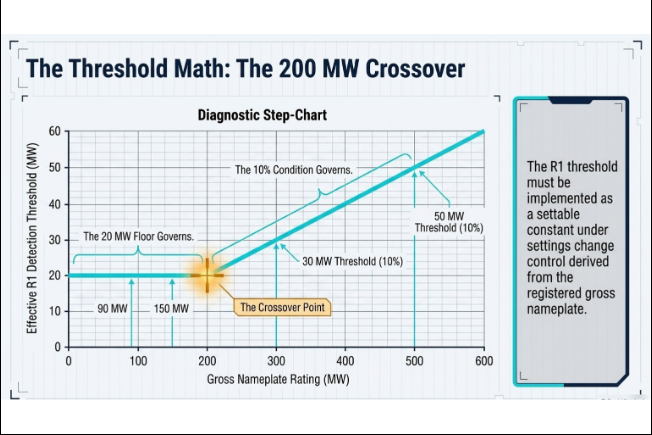
| Site Gross Nameplate | 10% Value | Governing R1 Detection Threshold |
|---|---|---|
| 90 MW | 9 MW | 20 MW — the 20 MW floor governs |
| 150 MW | 15 MW | 20 MW — the 20 MW floor governs |
| 200 MW | 20 MW | 20 MW — the crossover point |
| 300 MW | 30 MW | 30 MW — the 10% condition governs |
| 500 MW | 50 MW | 50 MW — the 10% condition governs |
Below 200 MW, every site triggers at 20 MW; above it, at 10%. The threshold must be implemented as a settable constant under settings change control, derived from the registered gross nameplate — because that registered value is itself part of the M1 evidence. Complete facility loss deserves its own thought: at most operating points a full-plant trip trivially exceeds the threshold, but the detection design must also behave sensibly when the plant is producing below threshold (dawn, dusk, curtailed) and when the event that takes the plant down also takes down the data path watching it. A compliant design addresses all three cases — in logic where possible, in the documented procedure where not.
4. Engineering R1 Detection on the SEL Platform — How the Experts Do It
Here is the good news Keentel delivers to most owners: R1 detection usually requires no new hardware. The instrumentation already in a modern collector substation — an SEL revenue meter, an SEL Real-Time Automation Controller (RTAC), and a plant historian — is fully capable of the job. What is missing is configuration, logic, and procedure. Getting those three right, however, involves engineering subtleties that separate a compliant implementation from one that quietly misses reportable events. These are the design elements Keentel engineers into every deployment:
4.1 Start at the measurement: know your meter’s update rate
The SEL-735 revenue meter — the workhorse at utility-scale plant metering points — processes its three-phase Real Power quantity (W3) on the IEC 61000-4-30 10/12-cycle method: a fresh value every 200 milliseconds at 60 Hz, five updates per second. That is five times faster than a 4-second detection window requires, which means the meter is essentially never the bottleneck. The bottleneck, when one exists, is the polling configuration between the meter and the RTAC — a Modbus or DNP3 client setting, not a hardware limit. Two details matter here that inexperienced integrators miss: first, verify which quantity the logic actually consumes (the SEL-735 exposes both loss-compensated W3 and uncompensated W3_UC — the design basis must name one); second, note that the meter’s onboard load-profile recorder bottoms out at 3-second intervals, so the 1-second archive that supports event evidence must live in the historian, not the meter. Knowing these platform facts up front is the difference between a one-week configuration effort and a month of trial and error.
4.2 The rolling window — and the sampling trap that misses real events
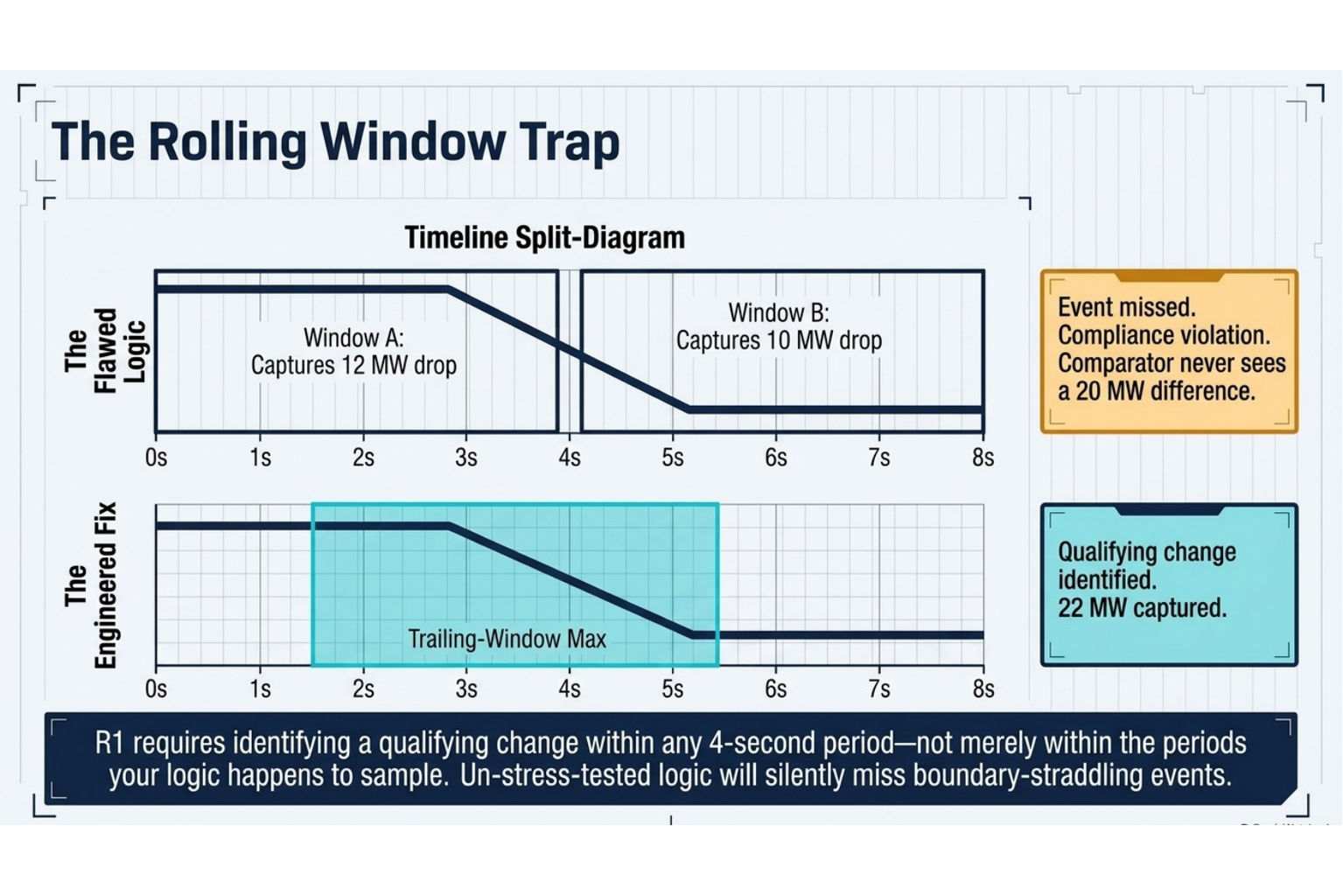
The intuitive way to detect “ΔP ≥ threshold in 4 seconds” in RTAC logic is a sample-and-hold: snapshot power every 4 seconds and continuously compare the live value against the snapshot. It is simple, it demonstrates beautifully — and it has a hole. A qualifying change that straddles the sampling boundary can escape detection entirely. Picture a 22 MW drop that begins just before the 4-second snapshot instant: 12 MW of it lands in one window, 10 MW in the next, and neither window ever presents the comparator with 20 MW. The event was real, reportable, and invisible. R1 requires identifying a qualifying change within any 4-second period — not merely within the periods your logic happens to sample. The fix costs one more function block: a second hold register on the same period but offset by half the window, with the comparisons OR’d — or, equivalently, comparing live power against the maximum of the samples over the trailing 4 seconds. Keentel writes a boundary-straddle test case into every commissioning plan — a split step deliberately placed across the sampling instant — because a detection scheme that has not been tested against this failure mode has not been tested.
4.3 Direction, data quality, and the blind-state alarm
- Detect both directions. R1’s text says “changes in Real Power output” — direction-neutral. A subtraction that only goes positive on drops silently halves the coverage. One absolute-value block closes it; if an owner elects drop-only detection, the technical basis belongs in the design record, not in an auditor’s imagination.
- Gate on data quality — but alarm the gate. When the metering communications path fails, the power tag freezes or collapses to zero, and naive logic declares a 100% plant trip. The standard practice is to block the trigger on a communications-failure status — correct, but only half the job. The failure state itself must raise its own distinct alarm, because a station event severe enough to sever the data path is precisely when a real R1 event may be occurring unseen. Blind periods must be visible, logged, and procedurally reviewed against historian data, breaker records, and operator logs.
- Time-stamp for the record, not the screen. An alarm-hold timer that stretches the trigger for HMI capture serves the operator; it does not serve the auditor. The trigger tag belongs in the RTAC sequence-of-events record with a station-clock timestamp, and in the alarm platform’s journal, so every assertion is permanently retrievable regardless of who acknowledged what.
- Build in a test mode. A switch block that substitutes a test value for the live power tag — access-controlled, logged, and with test assertions identifiable as tests — turns commissioning and periodic verification into a 30-minute exercise instead of a site mobilization, and produces the implementation evidence M1 asks for.
4.4 Exclusions: automate less than you think
The instinct is to automate all four R1 exclusions into the trigger logic — irradiance screening from pyranometer data, dispatch screening from setpoint comparison, and so on. Keentel’s field-proven position is more surgical: keep the trigger sensitive and apply exclusions at the documented disposition step. The compliance asymmetry drives this. An over-trigger costs an engineer fifteen minutes to disposition with evidence (“excluded — curtailment instruction, dispatch record attached”). An under-trigger — an automated screen wrongly suppressing a qualifying event — is a missed identification and a potential violation. The physics helps too: at a utility-scale site spread over hundreds of acres, cloud fields simply do not remove 20 MW in 4 seconds; historical-data review at real sites bears this out, which means irradiance screening ahead of the trigger buys almost nothing and risks much. Setpoint-comparison screening for dispatch events is more defensible and can be enabled where operating experience shows a nuisance-alarm burden — but any screening logic inserted ahead of the trigger is a compliance-critical settings change that deserves engineering review before deployment, every time.
5. Three Proven Architectures — From Fast-Track to Fleet-Grade
Keentel has engineered R1 compliance three different ways, and the right one depends on the owner's schedule, fleet, and appetite for independence:
| Architecture | How It Works | Best For |
|---|---|---|
| A — Existing-infrastructure fast track | Detection logic deployed in the plant's existing SEL RTAC, reading the SEL-735 Real Power value already polled for SCADA; alarm through the existing HMI platform; 1-second archiving in the existing historian. Zero new hardware — configuration, logic, and procedure only. | Tight compliance deadlines; sites with a healthy SEL meter/RTAC/historian stack; owners minimizing capital |
| B — Independent watchdog (SEL-451) | A dedicated SEL-451-class device applied monitor-only (no trip outputs): it measures three voltages and three currents directly from metering-class CT/PT tap-offs through new test switches, computes three-phase power internally at millisecond processing rates, runs the rolling-window logic in its programmable automation engine, and stores SER and oscillography onboard — detection and evidence survive even a total SCADA outage. Own GPS clock for ±1 ms stamps. | Fleet programs (a lead-site template repeats across sites at a fraction of first-site cost); owners who want compliance decoupled from integrator-maintained SCADA |
| C — Integrated with full DME (TESLA 4000) | R1 detection in the RTAC as in A, cross-marking event records in a dedicated ERLPhase TESLA 4000 disturbance fault recorder — so the moment an event is identified, waveform-grade evidence of it already exists. | Sites implementing PRC-028-1 disturbance monitoring — one program, two standards served |
All three are field-proven Keentel designs. A is the fastest path to a compliance date measured in weeks; B is the most robust and the natural fleet play; C is where every applicable site ultimately lands, because
PRC-028-1 is coming for the same facilities.
6. Where the TESLA 4000 Changes the Game — R2 Is a Data Problem
R1 tells you when something happened. R2 demands you explain why — root cause, ride-through performance, and Reactive Power response, within 90 days. Here is the uncomfortable truth about that analysis: 1-second SCADA data cannot answer R2’s questions. Root cause at an inverter-based plant lives in the waveforms — the voltage depression that preceded the trip, the phase-angle jump, the momentary cessation behavior of the inverter fleet, the reactive current injection during the sag. Those phenomena play out in cycles and milliseconds, invisible at 1-second resolution. An owner with only SCADA trends can say “output fell 43 MW at 14:32:07”; an owner with a disturbance recorder can say “a B-phase fault on the transmission system depressed voltage to 0.71 per unit for six cycles, and 60% of the inverter fleet entered momentary cessation instead of riding through — here is the COMTRADE record.” Only one of those owners closes an R2 analysis with confidence — and defends a PRC-029 ride-through inquiry while doing it.
This is why Keentel engineers PRC-030 detection and PRC-028-1 recording as one program, and why the ERLPhase TESLA 4000 anchors our dedicated-recorder designs. The platform brings exactly what R2 analysis consumes: multi-time-frame recording — transient fault records at sampling rates far above the 128 samples-per-cycle class, dynamic swing records, and true continuous disturbance recording that never stops, so even an event nothing triggered on is captured; deep onboard retention with dual redundant station-DC supplies; IRIG-B time synchronization for millisecond-aligned records; and native IEEE C37.111 COMTRADE output with C37.232 (COMNAME) file naming — the exact formats regulators and grid operators request. Around the recorder we deploy RecordBase Central Station, ERLPhase’s record-management platform: automated record collection both on recorder-initiated notification and on a polled schedule, automatic retrieval of continuous-recording data in 30-minute blocks, a searchable record database with integrated analysis graphics, and email notification on every record collected — which doubles as the automated failure-notification mechanism disturbance-monitoring standards reward. The net effect on PRC-030: when the R1 alarm asserts, the waveform evidence for the R2 analysis has already been captured, collected, named, and filed. The 90-day clock starts with the answer half-written.
The division of labor in one sentence: the SEL platform detects and disposes events; the TESLA 4000 platform explains them.
7. Evidence, Procedure, and the Audit — the Half of Compliance That Isn’t Wiring
Hardware and logic satisfy nothing by themselves; PRC-030-1 is audited on the documented process and its evidence. A complete Keentel R1 program delivers four stages in one controlled procedure.
Detect: the logic continuously evaluates the threshold.
Alert: assertion raises the HMI alarm, writes the time-stamped SER entry, and — critically — routes to a continuously monitored desk and a named notification list, because an alarm on a screen nobody watches is not identification. This is the “push.”
Capture: within one business day, the designated party exports the historian record for a window around the event and files it with the alarm-journal extract — the “pull,” and the M1 “actual data recording.”
Disposition: a reviewing engineer classifies every flagged event — qualifying R1 identification (which starts the R2 90-day clock) or excluded, with the exclusion category and its factual basis attached. No flag is ever discarded undocumented. The M1 mapping falls out naturally: the procedure is evidence element one; the as-left logic exports and a witnessed detection demonstration are element two; the SER, alarm journal, and historian exports are element three; the threshold determination tied to the registered nameplate is element four. Retention is sized so the archive always outlives the analysis window — Keentel’s standard is a 90-day rolling 1-second archive as the floor.
8. What Keentel Engineering Delivers
- PRC-030-1 R1 design basis & threshold determination — the governing threshold from your registered nameplate, exclusion handling, and the compliance interpretation, documented to audit grade.
- Detection logic engineering — rolling-window logic for SEL RTAC platforms (IEC 61131) or SEL-451 programmable automation, with boundary-straddle-proof sampling, data-quality gating, SER integration, and test mode — delivered implementation-ready for your integrator, or configured and bench-tested by Keentel.
- Third-party logic review — independent engineering review of an integrator’s proposed detection scheme, with written conditions of approval and the acceptance tests that prove them. The subtle failure modes in Section 4 are exactly what this review catches.
- Data-path and historian validation — meter-to-RTAC polling verification against the platform’s real update rates, 1-second archiving configuration, retention sizing, and retrieval workflow.
- The documented R1 process and evidence package — the four-stage procedure, alarm routing and notification design, disposition workflow, and M1 evidence mapping.
- Commissioning & witnessed verification — a test plan including the split-step boundary test, selectivity tests, comm-failure tests, and end-to-end retrieval — closed with a readiness memo your compliance file keeps.
- Independent watchdog fleet programs — SEL-451 monitor-only site kits: lead-site template engineering, per-site drawings and settings, owner procurement lists with part numbers, installer-ready packages, and per-site witnessed testing.
- Integrated PRC-028-1 / TESLA 4000 disturbance monitoring — channel design, trigger engineering, RecordBase deployment, COMTRADE/COMNAME evidence workflows, and the maintenance and failure-response programs that keep recorders audit-ready.
If your fleet has an R1 gap — or an R1 scheme nobody has stress-tested — talk to us before an event does the testing for you.
Keentel Engineering · www.keentelengineering.com · 813-389-7871.
Frequently Asked Questions — PRC-030-1 R1
Q: Does PRC-030-1 apply to my facility?
If you are the Generator Owner of a BES inverter-based resource — or of a non-BES IBR with aggregate nameplate of 20 MVA or more connected at 60 kV or above — yes. Solar, wind, and battery storage are all in scope. The effective date runs per the standard’s Implementation Plan and your registration category; Keentel confirms the governing date as part of every engagement.
Q: What exactly must my detection catch?
Two things: any complete loss of facility output, and any Real Power change that is simultaneously at least 20 MW and at least 10% of gross nameplate within a 4-second period — excluding resource-availability changes (clouds, wind), dispatch/ramping/planned work, configuration-driven disconnections, and PRC-004 misoperation reductions. Your effective threshold is the greater of 20 MW or 10% of nameplate.
Q: Do I need to buy new hardware for R1?
Usually not. If your site has a modern SEL revenue meter, an SEL RTAC, and a historian, R1 is a configuration-and-procedure project — detection logic in the RTAC, 1-second archiving in the historian, an alarm path, and the documented process. New hardware enters only if you choose the independent-watchdog architecture (a deliberate robustness upgrade, not a requirement) or if your site genuinely lacks a suitable measurement or logic platform — which a one-day Keentel assessment establishes definitively.
Q: Is 1-second data fast enough for a 4-second criterion?
Yes — for detection. A 1 Hz measurement stream gives the rolling-window logic four evaluations per window, and the SEL-735’s internal 200 ms update rate means the meter itself has five-fold margin; the engineering task is verifying the RTAC polls it at 1 Hz or better. But note the distinction: 1-second data detects events; it cannot explain them. The R2 root-cause analysis needs waveform-grade recording — see the disturbance recorder question below.
Q: Can’t I just sample power every 4 seconds and compare?
That is the classic implementation — and it contains a real defect. A qualifying change straddling the sampling boundary splits across two windows and can escape detection entirely (a 22 MW drop seen as 12 + 10). R1 covers any 4-second period, not just the ones your clock samples. The fix is a second offset hold register or a trailing-window maximum — one extra function block. Keentel’s commissioning plans include a deliberate boundary-straddle test because this failure mode is invisible in a simple demonstration.
Q: Should the logic screen out cloud and curtailment events automatically?
Less than you’d think. Over-triggering is compliance-safe — a flagged event dispositioned as excluded costs minutes and a paragraph. Under-triggering — an automated screen wrongly suppressing a real event — is a missed identification. Cloud fields physically cannot remove 20 MW from a utility-scale site in 4 seconds, so irradiance screening buys nothing; dispatch screening by setpoint comparison is reasonable where nuisance alarms prove burdensome. Keentel’s default: sensitive trigger, exclusions applied with evidence at the disposition step, and any pre-trigger screening treated as a compliance-critical settings change requiring engineering review.
Q: What happens when my SCADA comms fail — am I exposed?
Only if the design ignores it. Correct practice gates the trigger on data quality (so a frozen or zeroed tag doesn’t declare a phantom plant trip) AND alarms the failure state itself, with the procedure treating any blind period coincident with a generation change as a mandatory manual review from historian, breaker, and operator records. If independence from SCADA matters to you, the SEL-451 watchdog architecture keeps detection and onboard evidence alive through a complete SCADA outage.
Q: What evidence will an auditor actually ask for?
Measure M1’s four elements: (1) the documented identification process; (2) evidence it is implemented — as-left logic exports, settings records, and a witnessed detection test; (3) actual data recordings — SER entries, alarm journal, and historian exports for events; (4) the gross nameplate basis behind your threshold. Owners fail audits on element 2 and 3 hygiene far more often than on the logic itself — which is why the procedure and evidence workflow are half of every Keentel scope.
Q: An event fired — what happens next, and what are the clocks?
Same day: the alarm is logged and the event folder opened. Within a business day: the historian window around the event is exported and filed. Then the disposition: excluded (documented, closed) or qualifying — which starts R2’s 90-calendar-day analysis clock: root cause, ride-through and Reactive Power documentation, corrective-action assessment, and fleet applicability. If corrective actions are needed, R3 gives 60 days after the analysis to deliver a CAP or technical justification to the RC, BA, and TOP; R4 requires implementing and tracking the CAP to completion.
Q: Why do I need a disturbance recorder if PRC-030 detection runs on SCADA data?
Because R2’s questions — root cause, ride-through performance, reactive response — live in waveforms, not trends. Cycle-scale voltage depressions, phase jumps, and inverter momentary-cessation behavior are invisible at 1-second resolution. A dedicated recorder like the ERLPhase TESLA 4000 captures triggered records at well above the 128 samples-per-cycle class plus a continuous recording that never stops, in the COMTRADE format every investigation speaks. It is also precisely what PRC-028-1 requires of the same facilities — one integrated program covers both standards, and owners who already have the recorder close R2 analyses in days instead of scrambling for weeks.
Q: What does RecordBase Central Station add to a TESLA 4000?
The record-management layer auditors love: automatic collection the moment the recorder triggers (plus a polled sweep as backstop), automatic retrieval of continuous-recording data in 30-minute blocks, a searchable database with analysis graphics, IEEE C37.232-compliant file naming, and email notification on every record — which also serves as automated failure surveillance of the recording chain. When a grid operator requests event data, delivery becomes a filtered export instead of a project.
Q: We operate multiple sites. Does R1 scale?
Elegantly — if you template it. Keentel’s fleet approach engineers the lead site once (detection logic, drawings, procedure, test plan) and replicates at each additional site at a fraction of the cost, with only site-specific thresholds, ratios, and tags changing. One fleet-wide procedure, one evidence format, one training — and R2’s fleet-applicability question (“does this root cause affect your other facilities?”) becomes answerable instead of awkward. The independent SEL-451 watchdog kit is particularly fleet-friendly: identical hardware, owner-purchased from our part-numbered list, installed by your contractor from our drawings.
Q: Our SCADA integrator wrote detection logic. Do we still need an engineer?
Integrators are good at making logic run; a compliance engineer’s job is making it defensible. Independent review catches the failure modes that demos never show — boundary-straddle gaps, single-direction detection, comm-gate polarity, missing SER capture, unverified polling rates — and produces the written conditions of approval and acceptance tests that become your implementation evidence. Keentel performs exactly this review, typically in days, with markups the integrator can implement in a single remote session.
Q: How fast can a site get compliant?
On the existing-infrastructure path with a cooperative integrator: engineering package in about a week, logic implementation in a single remote deployment window, witnessed testing the following week — real deployments have gone from kickoff to readiness in under three weeks, with no procurement, no outage, and no site mobilization. The independent-watchdog path adds hardware lead time and an installation visit; the lead site typically engineers in about four weeks with additional fleet sites in about two each, in parallel.
Q: Where does Keentel fit among my owner, integrator, and O&M?
As the engineering authority: we produce the design basis, requirements, and procedures; your integrator implements in their systems under our review and conditions of approval; your O&M executes the procedure we deliver and train; and your compliance staff files evidence in the structure we hand over. On request we also act as owner’s engineer for the R2 analysis function itself — the standing capability to take an identified event through root-cause, ride-through documentation, and CAP support inside the 90-day window.

About the Author:
Sandip "Sonny" R. Patel, P.E.
IEEE Senior Member · Founder & CEO, Keentel Engineering
In 1995, Sonny Patel earned his Electrical Engineering degree from the University of Illinois. But degrees don't build legacies — action does.
For three decades, he has worked the power industry from every side of the table: 16 years as a utility engineer at Exelon/Commonwealth Edison; generation leadership across hydroelectric, industrial steam turbine, and a 9 GW renewable fleet; NERC Regional Entity Senior Compliance Engineer and Audit Team Lead, auditing some of the nation's largest utilities; and testing and commissioning lead on equipment up to 765 kV — the very top of the North American grid.Utility. Generator. Regulator. Consultant. Few engineers have seen all four seats. Fewer still have sat in them.
His experience spans nuclear, hydro, conventional generation, renewables, oil and gas, mining — and today's data centers, where he is authoring a three-book series on data center design. He is a Licensed Professional Engineer in six states and a Licensed Electrical Contractor in Florida (Unlimited EC) — he doesn't just design the work; he's qualified to stand behind its execution.Today, as Founder and CEO of Keentel Engineering, Sonny leads a nationwide team of engineers delivering substation design, power system studies, NERC compliance, and commissioning — done right, coast to coast.Three decades. Every side of the table. One standard: accountable engineering.
Services

Let's Discuss Your Project
Let's book a call to discuss your electrical engineering project that we can help you with.
About the Author:
Sandip "Sonny" R. Patel, P.E.
IEEE Senior Member · Founder & CEO, Keentel Engineering
In 1995, Sonny Patel earned his Electrical Engineering degree from the University of Illinois. But degrees don't build legacies — action does.
For three decades, he has worked the power industry from every side of the table: 16 years as a utility engineer at Exelon/Commonwealth Edison; generation leadership across hydroelectric, industrial steam turbine, and a 9 GW renewable fleet; NERC Regional Entity Senior Compliance Engineer and Audit Team Lead, auditing some of the nation's largest utilities; and testing and commissioning lead on equipment up to 765 kV — the very top of the North American grid.
Utility. Generator. Regulator. Consultant. Few engineers have seen all four seats. Fewer still have sat in them.
His experience spans nuclear, hydro, conventional generation, renewables, oil and gas, mining — and today's data centers, where he is authoring a three-book series on data center design. He is a Licensed Professional Engineer in six states and a Licensed Electrical Contractor in Florida (Unlimited EC) — he doesn't just design the work; he's qualified to stand behind its execution.
Today, as Founder and CEO of Keentel Engineering, Sonny leads a nationwide team of engineers delivering substation design, power system studies, NERC compliance, and commissioning — done right, coast to coast.Three decades. Every side of the table. One standard: accountable engineering.
Leave a Comment
Thank you for contacting us.
We will get back to you as soon as possible.
We will get back to you as soon as possible.
Oops, there was an error sending your message.
Please try again later.
Please try again later.
Related Posts

By SANDIP R PATEL
•
October 13, 2026
Plan data center capacity with land screening, MW-per-acre estimates, grid power availability and interconnection feasibility studies from Keentel Engineering.

By SANDIP R PATEL
•
October 11, 2026
Learn which fault produces the highest current at a bus, why SLG faults can exceed three-phase faults, and how symmetrical components determine fault duty.

By SANDIP R PATEL
•
October 11, 2026
Learn why zero-sequence current pulsates in the dq0 frame, how Park's transformation works, and how inverter controls handle unbalance and ground faults.

By SANDIP R PATEL
•
October 11, 2026
Explore grid inertia, RoCoF and frequency response, with swing equation calculations, frequency nadir analysis and US power system simulation examples.

By SANDIP R PATEL
•
October 11, 2026
Learn transient stability analysis, swing equation, equal-area criterion and critical clearing time with a 345 kV worked example and NERC TPL-001 guidance.

By SANDIP R PATEL
•
October 11, 2026
Learn why inverter controls become unstable in weak grids, how PLL bandwidth and SCR affect stability, and how PSCAD EMT studies identify and mitigate oscillations.

By SANDIP R PATEL
•
October 11, 2026
Learn how STATCOMs improve voltage stability and prevent FIDVR. Explore reactive power sizing, delayed fault clearing, NERC criteria and 138 kV simulation results.

By SANDIP R PATEL
•
October 10, 2026
Learn BESS DC sizing with power, energy, current and C-rate calculations, battery losses, degradation and a 100 MW/400 MWh utility-scale example.

By SANDIP R PATEL
•
October 10, 2026
Learn how BESS ROI is calculated using peak shaving, energy arbitrage, power quality and battery storage economics, with a practical 5 MW/10 MWh example.





