
A Coordinated Electric System Interconnection Review—the utility’s deep-dive on technical and cost impacts of your project.
Challenge: Frequent false tripping using conventional electromechanical relays
Solution: SEL-487E integration with multi-terminal differential protection and dynamic inrush restraint
Result: 90% reduction in false trips, saving over $250,000 in downtime
ERCOT enforces all of the above through simulation, which means your model is your compliance case. The bar is now high:
- Whole-facility scope. The model must represent everything the IT load, the UPS and power conversion, the cooling plant, the protection and control systems in formats compatible with ERCOT's study platforms (PSS/E, PSCAD, TSAT).
- Real control loops, not approximations. Generic textbook representations are unacceptable. The model must capture the actual inner control behavior of your power electronics.
- Hardware-validated converter models. For electronic loads, the PSCAD model must be benchmarked against actual hardware testing including voltage ride-through and subsynchronous response. A model assembled from standard PSCAD library blocks fails by definition, because a generic block has never been tested against your vendor's hardware. The good news: validation is a hardware-type test, so results for a given converter product are reusable across every facility that uses it.
- Format migration. Facilities that previously submitted the older composite load model (CMLD) format must transition to EPRI's PERC1 format.
- Three checkpoints. Models are reviewed before the stability study begins (no model, no study), before each quarterly stability assessment, and for electronic loads one final time before energization, when you must submit as-built models with a documented comparison against the previously studied data and a sworn attestation that the model matches actual field settings. ERCOT's review takes 10 business days, extendable by 20 put it on your critical path.
- A living obligation. Change your technology, controls, or relay settings in a way that affects ride-through including converting a crypto mining site to an AI data center — and you've triggered a new interconnection study, even if your megawatts don't change.
| Parameter | Detail |
|---|---|
| System | 230 kV / 138 kV transmission corridors, wind and wet-snow icing exposure |
| Data basis | 15 years of minute-resolution forced-outage records + regional weather observations |
| Core methods | Event grouping, MVA performance curves, time-to-95%-restore, area outage rate curves, fragility modeling, rerun-history benefits, exceedance and log-domain risk metrics |
| Headline result | ≈85% of maximum resilience benefit at 60% of original capital; worst-event restoration window cut from 11 days to 5 in rerun-history terms |
| Decision supported | Capital portfolio selection; resilience plan filing; post-investment verification framework |
| System / Topic | Governing Standard(s) | What It Controls |
|---|---|---|
| Overall plant electrical distribution | IEEE 141 (Red Book); IEEE 666 | Distribution architecture, voltage selection, design of generating station auxiliary service systems |
| Power system studies | IEEE 399 (Brown Book); IEEE 551 | Load flow, symmetrical/asymmetrical short circuit, motor starting methodologies down to the lowest LV panelboard |
| Protection & coordination | IEEE 242 (Buff Book); IEEE 3004.5; IEEE C37 series | Generator relaying (21, 59N, 87G), time-current coordination, selective clearing between LV and MV tiers |
| GSU / UAT / SST transformers | IEEE C57.12.00 and C57 family | Transformer ratings, impedance, testing, loading |
| HV switchyard breakers | IEEE C37.06 | AC high-voltage circuit breaker preferred ratings |
| MV switchgear (13.8 kV) | IEEE C37.20.2; IEEE C37.20.7 | Metal-clad construction, compartmentalization, vacuum breakers; arc-resistant design with plenum venting |
| MV cable | UL 1072; ICEA S-93-639 (NEMA WC 74) | Type MV-105 shielded cable, 133% insulation level for HRG systems |
| LV switchgear (480 V) | IEEE C37.13; UL 1558 | Metal-enclosed LV power circuit breaker switchgear to 635 V, draw-out ACBs with electronic trip units |
| Motor control centers | UL 845; NEMA ICS 18 | LV-MCC construction, MCCB/MCP protection for motors under ~200 HP |
| Motors | NEMA MG-1 | Motor performance, starting characteristics, service factors |
| DC & battery systems | IEEE 485; IEEE 946 | Lead-acid battery sizing (125/250 VDC), DC auxiliary system design |
| Grounding | IEEE 80; IEEE 142 (Green Book) | Ground grid step/touch potential limits; system grounding including high-resistance grounding |
| Lightning protection | IEEE 998 | Direct-stroke shielding of switchyard and outdoor generator structures |
| Arc flash & electrical safety | IEEE 1584; NFPA 70E | Incident energy calculation; worker safety boundaries and PPE |
| Fire protection | NFPA 850 | Fire protection and risk management for combustion turbine generating plants |
| Installation code | NEC (NFPA 70); NESC | Wiring methods inside the plant fence; overhead/outdoor clearances at the switchyard |
| Interconnection & compliance | FERC LGIP; NERC MOD-025/026/027, PRC-019/024/029, FAC-008 | Interconnection process, model validation, protection/ride-through coordination, facility ratings |
| IFC / Construction Deliverable | Purpose |
|---|---|
| Stamped IFC packages | Legal basis for construction; P.E. responsible charge |
| Final relay settings & TCCs | Protection as-installed matches the coordination study |
| Calculation archive | Owner records; NERC audit evidence trail |
| Commissioning procedures | Safe, sequenced energization; MOD field testing |
| Construction support | RFIs, field changes, FAT/SAT witness |
| As-builts & model handoff | Operating baseline; future study currency |
| Metric | Outcome |
|---|---|
| Defects found pre-occupancy | Three topology defects and one settings-mismatch family corrected before load migration; the shared-switchboard defect alone would have invalidated the concurrently-maintainable claim on day one |
| IST findings | Fourteen additional discrepancies surfaced under scenario testing (control logic, alarm mapping, one generator sequencing fault) — all closed before handover instead of during operations |
| Black-building test | Passed on second execution; the first attempt exposed the generator sequencing fault under true block load, exactly the failure the compressed plan would never have found |
| Handover quality | Operations team certified on the actual failure scenarios; corrected EOPs and settings documentation delivered as controlled documents |
| Business outcome | Occupancy proceeded three weeks behind the original date — against an independent estimate that the uncorrected sequencing fault carried a high probability of a full facility outage within the first year |
Part 2 — Frequently Asked Questions: Large Load Interconnection
An electric grid must remain in continuous balance — generation onto the grid must equal consumption from it at every instant. PJM achieves this balance, and prices it, through a layered market architecture. Each layer operates on a different time horizon, and each one touches project economics differently.
| Domain | Key Standards / Codes | What They Govern |
|---|---|---|
| Fire safety | NFPA 855; UL 9540 / UL 9540A | Installation requirements, separation, gas management; system safety listing and thermal-runaway fire testing |
| Grid interconnection | IEEE 1547 (distribution); IEEE 2800 (transmission IBRs) | Ride-through, reactive capability, power quality, and performance at the point of interconnection |
| Power quality | IEEE 519 | Harmonic distortion limits at the PCC |
| Protection & grounding | IEEE 80 / 81 / 142; C37 series | Grounding system design and testing; protective relaying |
| Reliability compliance | NERC standards (incl. PRC ride-through requirements) | Registered-entity obligations for grid-connected storage |
Where Does Zero-Sequence Current Come From in Inverter-Based Plants?
September 01, 2026 | Blog
Ground Fault Current at an Inverter-Based Plant Is Set by the Transformer, Not the Inverter — and Why That One Fact Governs Grounding, Overvoltage, Protection, and the Interconnection Review
1. Executive Summary
Everyone working with inverter-based resources has internalised one fact: the fault current contribution is small, limited by the converter controls to a modest multiple of rated current. That fact is correct for balanced faults and it is deeply misleading for ground faults, because it describes the positive- and negative-sequence networks and says nothing at all about the zero-sequence network.
Zero-sequence current does not come from the inverters. It cannot. The inverters sit behind a transformer winding that either blocks it or does not, and where a grounded-wye winding faces the system, that winding is itself a zero-sequence source. Its strength is set by the transformer’s zero-sequence impedance and by any neutral impedance in the path — quantities that have nothing to do with the converter current limit and everything to do with the transformer specification.
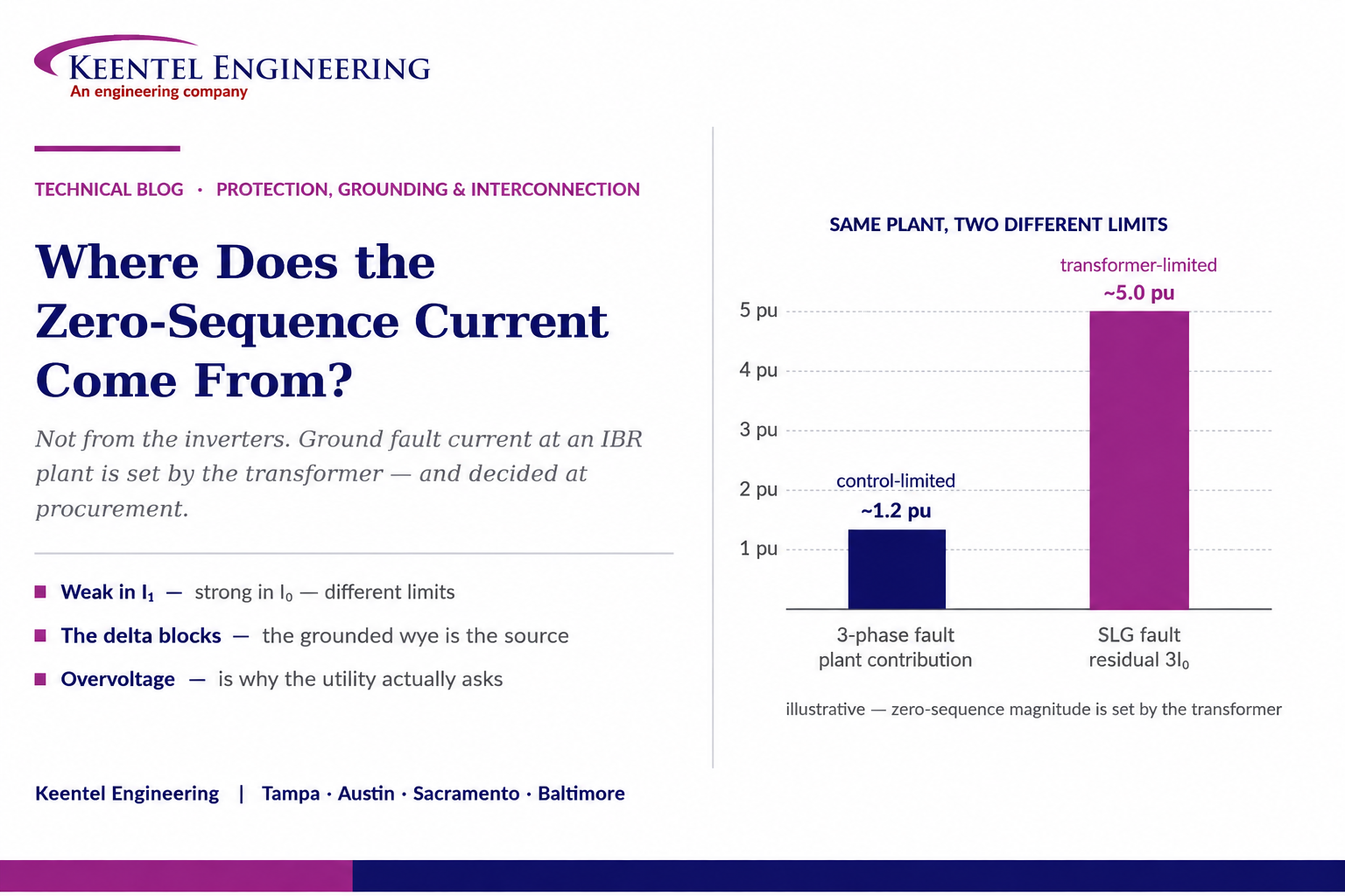
The engineering consequence is an asymmetry that catches experienced people. The same plant can be a weak source in the positive-sequence sense and a strong source in the zero-sequence sense. It may contribute little more than rated current to a three-phase fault at the point of interconnection while contributing several times that in residual current to a single line-to-ground fault at the same location. A study that applies the converter current limit across all three sequence networks will understate ground fault duty by a large factor, and the protective device settings and coordination derived from it will be wrong.
That single fact then propagates into everything an interconnecting utility actually cares about: whether the plant is an effective grounding source and therefore whether unfaulted phase voltages stay within arrester and insulation capability when the utility source is removed; whether the plant desensitises the utility’s ground overcurrent protection through infeed; how the collector system detects its own ground faults; what cable insulation level is appropriate; and what the transformer specification has to say about core construction and tertiary windings.
This paper works through the physics, the transformer connection cases including the ones the common diagrams omit, the two separate grounding decisions every plant has, effective grounding and ground fault overvoltage, grounding transformer sizing, the protection consequences, the modelling errors that produce confident wrong answers, and the study set that resolves it. It includes three illustrative case scenarios and a twenty-five question FAQ.
The sentence to carry out of this paper
An inverter-based plant is control-limited in the positive and negative sequence and transformer-limited in the zero sequence.
Those are different limits, set by different equipment, decided by different people, at different points in the project. Applying one to the other is the error the whole topic turns on.
2. The Question Behind the Question
Where did the zero-sequence current go?" is the right question asked slightly backwards. For most inverter-based plants the more useful framing is: where did it come from, given that it did not come from the inverters?
The answer is that it came from a transformer neutral. When a grounded-wye winding faces the faulted system, that winding provides a path for zero-sequence current to circulate to ground, and the transformer becomes a zero-sequence source in exactly the way a grounding bank does. The inverters supply the real power that ends up flowing, but the sequence-network path — and therefore the magnitude — is a transformer property.
That reframing matters because it relocates the design decision. If ground fault current at the point of interconnection is a transformer property, then it is decided in the transformer specification, months before anyone runs a protection study, and it is fixed by the time the equipment is on the pad. Getting it wrong is not a settings problem.
3. Zero Sequence Needs a Path, Not a Source Rating
The symmetrical component decomposition splits an unbalanced condition into three balanced sets. The positive- and negative-sequence sets sum to zero at any node and require no return conductor. The zero-sequence set does not: all three phase quantities are equal in magnitude and in phase, so their sum is three times the individual value and it must return through ground, a neutral conductor, or a grounded winding.
That is why the zero-sequence network is topologically different from the other two. It is not simply the positive-sequence network with different impedance values. Its connectivity depends on the transformer winding connections and on where neutrals are grounded, and a transformer that is a series element in the positive-sequence network can be an open circuit, a shunt to ground, or both, in the zero-sequence network.
Two consequences follow immediately. First, no amount of current available on one side of a transformer produces zero-sequence current on the other side unless the connection permits it. Second, a grounded-wye winding is a shunt path to ground in the zero-sequence network whether or not there is any generation behind it, which is precisely why grounding banks work.
4. What the Delta Winding Actually Does
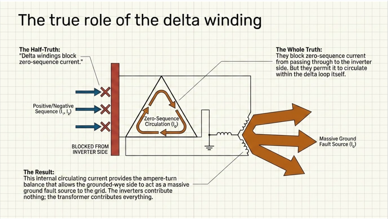
The delta winding is described as blocking zero-sequence current, which is true and incomplete in a way that causes confusion.
A delta winding does not permit zero-sequence current to pass through the transformer to the other winding, because there is no path for the equal, in-phase currents to exit the delta into the external circuit. What it does permit — and this is the part often left out — is zero-sequence current to circulate within the delta itself. That circulating current is what allows the other winding, if it is grounded wye, to carry zero-sequence current at all. The delta supplies the ampere-turn balance.
So the correct statement for a delta on the inverter side and grounded wye facing the system is that the inverters contribute no zero-sequence current, and the transformer contributes a great deal. Both halves are true simultaneously, and only one of them is usually said out loud.
The correction that matters most
A common summary says that with a delta on the inverter side, "the 3I0 seen by protection may be small." That holds only for faults on the delta side, or where nothing else provides a grounded path.
For a ground fault on the system side of a delta / grounded-wye main power transformer, the residual current is not small. The grounded-wye winding is the zero-sequence source, and it is a strong one.
5. The Asymmetry That Surprises People
Putting the two behaviours side by side is the fastest way to see why conventional intuition fails.
| Positive and negative sequence | Zero sequence | |
|---|---|---|
| What sets the magnitude | The converter current limit and its control priority logic | The transformer zero-sequence impedance, the neutral connection, and any neutral impedance |
| Typical order of magnitude at the point of interconnection | A small multiple of plant rated current, for a controlled duration | Governed by transformer impedance in the same way a conventional grounding source would be — frequently several times larger |
| Who decides it | The inverter manufacturer and the control configuration | The transformer specification, written during procurement |
| When it is fixed | Configurable, and changeable by firmware or settings | Fixed when the transformer is manufactured |
| How it behaves during the fault | Time-varying, control-dependent, and non-linear once the limiter saturates | A passive impedance path — predictable and stable |
| What it does to protection | Overcurrent may not reach pickup; sequence angle relationships are control outputs | Ground overcurrent may see substantial current; the plant becomes an infeed and a polarising source |
The practical test is simple and worth applying to any study report that crosses your desk. Compare the plant’s contribution to a three-phase fault at the point of interconnection with its residual contribution to a single line-to-ground fault at the same point. If the two are similar, the model has almost certainly applied the converter current limit to the zero-sequence network, and the ground fault results are wrong.
6. Transformer Connection by Connection
The common diagrams show two cases. There are more, and several of the omitted ones are in service.
| Connection (system side / inverter side) | Zero-sequence behaviour at the system side | Consequences |
|---|---|---|
| Grounded wye / delta | The grounded-wye winding is a zero-sequence source; residual current is substantial and set by transformer zero-sequence impedance | Plant is an effective grounding source, limiting ground fault overvoltage. It also becomes a permanent zero-sequence infeed that affects utility ground relay coordination and carries system unbalance current continuously |
| Delta / grounded wye | No zero-sequence path to the system side; the plant contributes essentially no residual current | Plant is not a grounding source. Ground fault overvoltage on the unfaulted phases becomes the governing concern, and a separate grounding bank is usually required |
| Grounded wye / grounded wye, with a delta tertiary | Zero-sequence path exists; the tertiary provides the ampere-turn balance and largely determines the zero-sequence impedance | Behaves broadly like the grounded-wye / delta case from the system side. The tertiary must be rated for the duty it will carry |
| Grounded wye / grounded wye, no tertiary | Zero-sequence behaviour depends on core construction and is not determined by the connection alone | The single most misunderstood case. See Section 7 |
| Delta / delta, or ungrounded wye anywhere in the path | No zero-sequence path | No ground fault current contribution and no grounding reference; ground fault detection and overvoltage both require deliberate provision |
| Grounded wye with neutral impedance / delta | Zero-sequence source with magnitude deliberately limited by the neutral resistor or reactor | A design lever for reducing ground fault duty while retaining a grounding reference — at the cost of moving the system away from effective grounding if taken too far |
7. Core Construction and the Missing Tertiary
A grounded-wye to grounded-wye transformer with no delta tertiary is the case that most often produces an incorrect model, because the connection diagram does not tell you what the zero-sequence impedance is. The core construction does.
In a three-legged core-form transformer, zero-sequence flux is in phase in all three legs and cannot return through the core; it returns through the tank and the surrounding structure, which presents a comparatively low reluctance path. The result is a moderate zero-sequence impedance — the unit behaves somewhat as though a delta winding were present, which is why the effect is sometimes described as a phantom or virtual delta. In a shell-form transformer, or a five-legged core-form design, the zero-sequence flux has a genuine return path in the core, and the zero-sequence impedance is very high unless a delta winding is provided.
Two units with identical nameplate connections and identical positive-sequence impedance can therefore behave completely differently in the zero-sequence network. The zero-sequence impedance is a test quantity, not a derived one, and it belongs in the specification and in the test report.
A specification line worth adding
Require the zero-sequence impedance to be measured and reported in the factory test report, for each winding combination, and require it to be stated in the purchase specification rather than left to the manufacturer’s standard design.
A study performed on an assumed zero-sequence impedance, for a transformer whose actual value differs by a factor of several, is not a study of that plant.
8. Two Grounding Decisions, Not One
Almost every discussion of this subject treats grounding as a single decision at the main power transformer. A utility-scale inverter-based plant has at least two, and they are made by different people for different reasons.
8.1 The System-Facing Decision
The connection and grounding of the main power transformer winding that faces the utility determines whether the plant is a zero-sequence source to the transmission or distribution system. This is the decision the interconnecting utility cares about, because it governs ground fault overvoltage on the utility system and the behaviour of utility ground protection. It is usually driven by the utility’s grounding practice and stated in the interconnection requirements.
8.2 The Collector-Facing Decision
The connection and grounding on the collector side is a separate question with its own consequences, and it is frequently left to whatever the transformer vendor proposed. A delta collector-side winding leaves the medium-voltage collector system ungrounded unless a grounding bank is provided on the collector bus. An ungrounded collector produces very little current for a single line-to-ground fault, which sounds attractive until the implications are worked through: the fault is difficult to detect and locate, the unfaulted phase voltages rise toward line-to-line magnitude and stay there, cable insulation is stressed continuously rather than momentarily, and a second ground fault on a different phase becomes a phase-to-phase fault through earth.
The inverter pad-mount transformers add a third layer. A delta winding on the collector side of each pad transformer isolates the inverter from collector zero-sequence quantities and is common practice; a grounded-wye arrangement does not. The choice affects where a collector ground fault is seen and by what.
9. Effective Grounding and Ground Fault Overvoltage
The reason utilities examine plant grounding at all is not ground fault current. It is overvoltage.
Consider a ground fault on a utility circuit and an upstream device that opens, leaving a section energised only by the interconnected plant. If the plant is not an effective grounding source for that section, the neutral shifts and the voltage on the two unfaulted phases rises toward line-to-line magnitude. The magnitude and duration depend on the zero-sequence to positive-sequence impedance relationship at that point, and the exposure is to surge arresters and to equipment insulation — arresters selected for an effectively grounded system have a continuous operating voltage rating chosen on the assumption that this cannot happen.
Effective grounding is defined by the relationship between the zero-sequence and positive-sequence impedances at the point in question, with commonly applied criteria that the zero-sequence reactance not exceed roughly three times the positive-sequence reactance and that the zero-sequence resistance stay within a comparable bound. Meeting those criteria keeps the coefficient of grounding low enough that arresters rated for an effectively grounded system remain within their capability.
This is an assessment, not an assumption, and it is one of the most common causes of late-stage interconnection redesign. It is examined during utility review, it depends on the transformer that was ordered, and the remedy when it fails is a grounding bank, a different transformer, or a change to the neutral arrangement — all of which have lead time.
10. Grounding Transformers
Where the plant needs a zero-sequence source that its main transformer does not provide, a grounding bank supplies one. Two arrangements dominate: a zig-zag winding, and a grounded-wye to delta bank whose delta is not otherwise loaded.
Sizing is not a nameplate kVA exercise. The design quantities are the zero-sequence impedance required to achieve the grounding objective, the continuous current the bank will carry from normal system unbalance and from harmonic content, and the short-time thermal capability for the fault current it will pass during the maximum clearing time. A bank sized only for the fault duty and not for continuous unbalance overheats in service; a bank sized only for continuous duty fails during a fault.
Three further considerations are routinely missed. The bank is a permanently connected zero-sequence source, so it affects utility ground relay coordination whenever it is in service, including when the plant is not generating. It needs its own protection, typically including a neutral overcurrent element coordinated with the system ground protection. And whether it remains connected when the plant disconnects is a design decision with consequences for both grounding and coordination — a grounding bank that opens with the plant provides no grounding at the moment it is most needed.
11. What This Does to Protection
The protection consequences follow directly from the plant being a zero-sequence source at the point of interconnection.
- Ground overcurrent infeed. Zero-sequence current supplied by the plant for a fault beyond the point of interconnection reduces the residual current the utility’s upstream relay measures, extending its clearing time. This is the ground-fault analogue of the distance infeed problem, and it appears as soon as the plant is in service regardless of whether it is generating.
- Directional ground elements. A plant transformer neutral is a valid polarising source for protection at the plant, and it changes the direction sense seen by utility protection. Where zero-sequence voltage polarisation is used, the plant’s grounding source alters the voltage distribution the relay measures.
- Ground distance reach. Apparent impedance for ground faults depends on the zero-sequence current distribution, so adding a grounding source at an intermediate point changes the reach of ground distance elements that were set without it.
- Sympathetic operation. Zero-sequence current flowing from the plant toward a fault elsewhere can operate non-directional ground elements on healthy circuits.
- Mutual coupling. On parallel circuits, zero-sequence mutual coupling already complicates ground fault analysis; adding a grounding source changes the coupling contribution and the resulting relay quantities.
- Plant-side protection. The main transformer needs restricted earth fault or neutral overcurrent protection sized for the actual zero-sequence duty, with current transformer ratios chosen for the real magnitude rather than an assumed small one — a point Case A turns on.
- Collector ground fault detection. On an ungrounded collector, detection is by neutral displacement voltage rather than by current, and identifying which feeder is faulted requires deliberate provision rather than a default overcurrent scheme.
12. Negative Sequence: The Other Half
The graphic’s closing reminder about negative sequence is well placed, and the reason it belongs alongside the zero-sequence discussion is that the two are governed by completely different mechanisms at an inverter-based plant.
Zero-sequence behaviour is a passive network property. It is stable, predictable, and set by transformers and grounding. Negative-sequence behaviour is a control property. Where the converter has a dedicated negative-sequence regulator, the magnitude and the angular relationship to negative-sequence voltage are configurable and defined; the interconnection performance standard for inverter-based resources requires negative-sequence injection during unbalanced faults and constrains the angle so that conventional protection continues to work. Where the converter has no such regulator, negative-sequence output is a residue of the positive-sequence control loop operating on an unbalanced input, and its angle is not stable.
For a protection engineer analysing an unbalanced fault at an inverter-based plant, that produces a three-part picture worth stating explicitly: the zero-sequence quantities are trustworthy and transformer-determined, the positive-sequence quantities are control-limited, and the negative-sequence quantities may or may not be controlled depending on the converter and its configuration. Elements that rely on the third category — negative-sequence directional and phase selection in particular — need verification rather than assumption.
13. Modelling Errors That Produce Confident Wrong Answers
| Error | Why it happens | What it produces |
|---|---|---|
| Applying the converter current limit to the zero-sequence network | The plant is described in every summary as a current-limited source, and the limit gets applied uniformly | Ground fault duty understated by a large factor; ground relay settings, coordination and equipment duty all derived from the wrong number |
| Assuming zero-sequence impedance from the connection diagram | For grounded-wye to grounded-wye without a tertiary, the connection does not determine the answer — core construction does | Zero-sequence impedance wrong by a factor of several in either direction, depending on which way the assumption fell |
| Omitting the grounding bank from the model | It is a small piece of equipment with no generation behind it and is easy to overlook | The plant appears not to be a grounding source when it is, or the reverse |
| Attributing the zero-sequence contribution to the plant rather than the transformer | Convenient shorthand in study reports | Incorrect conclusions about what happens when the plant is offline, since the transformer grounding remains regardless of generation |
| Modelling the plant as an equivalent synchronous machine | Legacy modelling practice and tool defaults | Wrong in the positive and negative sequence in one direction and potentially wrong in the zero sequence in the other |
| Ignoring the collector-side grounding entirely | The study scope is written around the point of interconnection | Collector ground faults undetectable, cable insulation level unverified, and overvoltage duty unassessed |
| Using one operating configuration | The single-line looks the same in every case | Missing the cases that govern — plant offline with transformer energised, one collector feeder out, grounding bank out of service |
14. The Study Set
The following is what a defensible scope looks like for the grounding and ground fault side of an inverter-based interconnection. Several items are outside the typical short-circuit study scope and are the ones most often missing.
- Sequence network development with the transformer zero-sequence impedance taken from factory test data rather than assumed, and with core construction and any tertiary explicitly represented.
- Ground fault current calculation at the point of interconnection and through the plant, distinguishing the plant’s zero-sequence contribution from its positive- and negative-sequence contribution rather than reporting a single current-limited figure.
- Effective grounding assessment against the criteria the interconnecting utility applies, for the configurations that govern — including the case where the plant is not generating but the transformer remains energised.
- Ground fault overvoltage analysis for the islanded and partially separated conditions, with the resulting duty compared against surge arrester capability and equipment insulation.
- Surge arrester selection review, since arrester ratings depend on whether the system is effectively grounded at that point.
- Grounding bank sizing where required: zero-sequence impedance to meet the grounding objective, continuous unbalance and harmonic duty, short-time thermal rating for the maximum clearing time, and its own protection.
- Collector system grounding design, including ground fault detection method, faulted feeder identification, and the cable insulation level appropriate to the grounding arrangement and clearing time.
- Ground protection coordination across the point of interconnection, including the infeed effect on utility relays and the sympathetic operation exposure.
- Negative-sequence behaviour verification for the elements that depend on it, using the manufacturer’s validated model at the configuration actually deployed.
- Re-verification triggers: any transformer replacement, grounding bank change, collector reconfiguration, or converter configuration change that affects sequence behaviour.
15. Case Studies
The following scenarios are composite and illustrative. They are constructed from patterns that recur across inverter-based generation and storage projects to show how these problems develop and how they are found. They do not describe any specific client, site, project, manufacturer, or utility.
15.1 Case A — The Ground Fault Duty That Was Not Small
Situation. A utility-scale solar plant with a delta collector-side, grounded-wye system-side main power transformer. The interconnection study characterised the plant as a current-limited source, and the plant-side protection was set on that basis — including the current transformer ratio and pickup for the transformer neutral overcurrent element.
What the review found. For a single line-to-ground fault at the point of interconnection, the residual current supplied through the grounded-wye winding was several times the plant’s positive-sequence contribution to a three-phase fault at the same location, because it was set by the transformer zero-sequence impedance rather than by the converter limit. The neutral current transformer had been sized for the assumed small value and would have saturated heavily during a real fault. The utility’s ground overcurrent coordination had also been checked against the understated plant contribution.
Exposure. A saturated neutral current transformer delivers reduced and distorted current at the moment the protection needs accuracy, so the neutral element would have been slow or absent. The coordination check with the utility was invalid, meaning selectivity for ground faults across the point of interconnection had not actually been demonstrated.
Remedy. The sequence network was rebuilt with the transformer zero-sequence impedance taken from the factory test report. The neutral current transformer ratio and accuracy class were re-selected with a saturation calculation for the actual offset fault current, the neutral element was reset, and the ground coordination was redone with the utility and reissued.
Lesson. Apply the comparison test to any study report: if the plant’s residual contribution to a single line-to-ground fault looks similar to its contribution to a three-phase fault, the converter current limit has been applied to the zero-sequence network and the ground results are wrong.
15.2 Case B — The Effective Grounding Finding After the Transformer Was Ordered
Situation. A storage project specified its main power transformer early to protect a long lead time. The connection selected did not provide a grounded-wye winding facing the utility. The interconnection application proceeded in parallel, and the utility’s detailed review of grounding requirements came later in the process.
What the review found. The utility required the plant to be an effective grounding source at the point of interconnection under its grounding practice. As specified, the plant was not, and ground fault overvoltage on the unfaulted phases during a partial separation would have exceeded what the arresters selected for an effectively grounded system could tolerate. A secondary finding: the zero-sequence impedance had been assumed rather than taken from a test value, and the transformer as designed would not have met the assumption even had the connection been correct.
Exposure. Arrester failure and equipment insulation stress during a credible system condition, and — more immediately — an interconnection approval that could not be granted with the equipment as ordered.
Remedy. A grounding bank was added at the point of interconnection, sized for the zero-sequence impedance needed to satisfy the effective grounding criteria, for the continuous unbalance and harmonic duty, and for the short-time thermal duty at the maximum clearing time. Its protection was designed and coordinated, and the decision on whether it remains connected when the plant is offline was made deliberately and documented. Arrester selection was re-verified against the revised grounding.
Lesson. Effective grounding is decided in the transformer specification, and the transformer is ordered long before the utility’s grounding review concludes. Raise the grounding question at specification stage, with the utility, and get the zero-sequence impedance into the purchase requirements and the factory test scope.
15.3 Case C — The Collector Ground Fault Nobody Could See
Situation. A plant whose main power transformer presented a delta winding to the collector system, with no grounding bank on the collector bus. The collector was therefore ungrounded. Cable was specified at the insulation level appropriate to fast ground fault clearing.
What the review found. A single line-to-ground fault on a collector circuit produced only capacitive charging current — far below any overcurrent pickup — so it was neither cleared nor located. The unfaulted phase voltages rose toward line-to-line magnitude and remained there, applying continuous stress to cable insulation specified on the assumption of a short excursion. The condition could persist for an extended period, and a subsequent ground fault on a different phase on any collector circuit would have become a phase-to-phase fault through earth, with the corresponding fault duty and equipment damage.
Exposure. Undetected sustained faults, accelerated insulation ageing across the whole collector system rather than at the fault location alone, and a credible path to a severe double fault.
Remedy. A grounding bank was added on the collector bus, sized to produce enough ground fault current for reliable detection while keeping the duty within cable and equipment capability, with its own thermal rating established for the clearing time. Neutral displacement detection was provided for alarm, with faulted feeder identification, and the cable insulation level was reassessed against the revised grounding and clearing time.
Lesson.
The collector-side grounding decision is separate from the system-side one and is often made by default rather than by design. An ungrounded collector is a legitimate choice only if ground fault detection, insulation level, and overvoltage duration have all been engineered for it.
16. Reading the Graphic Correctly
The residual current is not small on the grid side of a delta / grounded-wye transformer
The statement that the inverters contribute little or no zero-sequence current is correct. The inference that the residual current seen by protection is therefore small does not follow where a grounded-wye winding faces the fault. The grounded-wye winding is the zero-sequence source, and its strength is a transformer property.
"Inverter and system grounding both contribute" needs care
For a grounded-wye to grounded-wye transformer, zero-sequence current can pass — but the inverters behind it are still not a zero-sequence source unless they are themselves a grounded four-wire source, which most are not. And the magnitude depends on core construction and on whether a delta tertiary is present, neither of which appears on a connection diagram.
The list of what affects ground fault current is incomplete
Inverter topology and controls, transformer connection and grounding, system grounding, and fault location and network impedance are all correct. Missing are transformer core construction and tertiary winding, the presence and rating of any grounding bank, and neutral impedance where fitted — all of which change the answer materially.
Overvoltage is the reason the utility asks
The graphic frames the topic as ground fault current magnitude. The interconnecting utility’s primary concern is usually the opposite condition: what happens to the unfaulted phase voltages when the plant is left supporting a section with a ground fault on it. Effective grounding, arrester capability, and insulation coordination are the substance of the review, and they belong in any complete treatment.
There are two grounding decisions
The system-facing and collector-facing arrangements are separate, are decided by different parties for different reasons, and have separate consequences. A treatment that shows only the main power transformer addresses half the plant.
17. Keentel Protection, Grounding, and Interconnection Services
Keentel Engineering works across exactly the boundary this paper describes — where a transformer specification decision, a grounding assessment, a protection setting, and an interconnection requirement all turn out to be the same question.
17.1 Grounding and Overvoltage
- System grounding design and effective grounding assessment at the point of interconnection, against the interconnecting utility’s criteria and for the configurations that govern, including plant-offline cases.
- Ground fault overvoltage analysis for islanded and partially separated conditions, with duty compared against arrester capability and equipment insulation.
- Grounding transformer specification and sizing — zero-sequence impedance, continuous unbalance and harmonic duty, short-time thermal rating, protection, and connection philosophy.
- Surge arrester selection and insulation coordination review.
- Ground grid design and step-and-touch analysis.
17.2 Power System Studies
- Short-circuit and sequence network studies with inverter-based resources represented correctly in each sequence network — control-limited in positive and negative sequence, transformer-determined in zero sequence.
- Ground and phase protective coordination and selectivity across the point of interconnection, including infeed and sympathetic operation assessment.
- Arc-flash analysis, load flow, motor starting, harmonic and power quality studies, and grid strength assessment.
- Electromagnetic transient modelling for control interaction, weak-grid stability, ride-through verification, switching and overvoltage transients, and fault-response behaviour at protection timescales.
17.3 Protection and Control
- Protection philosophy, zone definition, and scheme design for generation and storage plants and their interconnection facilities.
- Relay setting calculations including transformer neutral and restricted earth fault elements sized for the actual zero-sequence duty, with current transformer ratio, accuracy class and saturation calculations in the design record.
- Collector system ground fault detection design, faulted feeder identification, and cable insulation level assessment against the grounding arrangement and clearing time.
- Settings audits against the study of record, and protection review triggered by transformer, grounding, collector, or converter configuration changes.
17.4 Interconnection and Equipment Specification
- Point-of-interconnection engineering, substation and collector system design, and interconnection application and study-phase technical support.
- Transformer specification support including connection, grounding, tertiary, core construction, and the zero-sequence impedance test requirements that make a study defensible.
- Design review of EPC and vendor submittals, QA/QC of third-party study packages, and commissioning and verification support.
Keentel Engineering holds a Florida Certificate of Authorization and maintains offices in Tampa, Austin, Sacramento, and Baltimore, supporting projects across the interconnections.
18. Frequently Asked Questions
Essentially no, in the ordinary three-wire arrangement. Zero-sequence current requires equal, in-phase currents in all three phases returning through ground or a neutral, and a three-wire converter has no such path. What produces zero-sequence current at an inverter-based plant is a grounded-wye transformer winding, not the inverters.
From the transformer. A grounded-wye winding facing the faulted system is a zero-sequence source in the same way a grounding bank is, and its strength is set by the transformer zero-sequence impedance and any neutral impedance. The inverters supply real power; the sequence path and the magnitude are transformer properties.
Because the industry has correctly internalised that inverter-based plants are weak fault current sources, and that intuition comes from the positive-sequence network. The same plant can be weak in positive sequence and strong in zero sequence. The two limits are set by different equipment.
Compare the plant’s contribution to a three-phase fault at the point of interconnection with its residual contribution to a single line-to-ground fault at the same point. If they look similar, the converter current limit has been applied to the zero-sequence network and the ground fault results are wrong.
It prevents zero-sequence current from passing through the transformer to the other winding, and it permits zero-sequence current to circulate within the delta itself. That circulation is what allows a grounded-wye winding on the other side to carry zero-sequence current at all. Both statements are true at once, and only the first is usually said.
Only for faults on the delta side, or where nothing else provides a grounded path. For a ground fault on the system side of a delta to grounded-wye main power transformer, the residual current is not small — the grounded-wye winding is the source.
Zero-sequence current can pass, but the magnitude depends on whether a delta tertiary is present and, if not, on the core construction. The connection diagram alone does not determine the zero-sequence impedance.
In a three-legged core-form transformer, zero-sequence flux cannot return through the core and returns through the tank and structure, giving a moderate zero-sequence impedance — behaving somewhat as though a delta were present. In a shell-form or five-legged core-form design, the flux has a genuine core return path and the zero-sequence impedance is very high absent a delta winding. Identical nameplates, very different behaviour.
State the required zero-sequence impedance, require it to be measured and reported in the factory test report for each winding combination, and state the connection, grounding arrangement, and any tertiary explicitly rather than accepting the manufacturer’s standard design. A study built on an assumed value for a transformer that differs is not a study of that plant.
It is a defined relationship between zero- and positive-sequence impedances at a point — commonly that zero-sequence reactance not exceed roughly three times positive-sequence reactance, with a comparable bound on resistance. Utilities care because it bounds how far unfaulted phase voltages rise during a ground fault, and surge arresters selected for an effectively grounded system are rated on the assumption that it holds.
When a ground fault occurs and an upstream device opens, leaving a section energised only by the interconnected plant, an ineffectively grounded plant allows the neutral to shift and the unfaulted phase voltages to rise toward line-to-line magnitude. The exposure is arrester duty and equipment insulation, and it is the primary reason grounding is reviewed at interconnection.
Because the transformer is specified early to protect a long lead time, and the utility’s detailed grounding review concludes later. By the time the finding arrives, the connection and the zero-sequence impedance are fixed. The remedy — a grounding bank, a different transformer, or a neutral change — all carry lead time of their own.
By three separate quantities: the zero-sequence impedance required to meet the grounding objective, the continuous current from system unbalance and harmonics, and the short-time thermal capability for the fault current it passes during maximum clearing time. Sizing for fault duty alone produces a bank that overheats in service; sizing for continuous duty alone produces one that fails during a fault.
That is a deliberate design decision with consequences both ways. A bank that disconnects with the plant provides no grounding at the moment it may be most needed. A bank that stays connected is a permanent zero-sequence source affecting utility ground coordination whenever the transformer is energised. Decide it explicitly and document it.
Mainly through infeed. Zero-sequence current supplied by the plant for faults beyond the point of interconnection reduces the residual current the utility relay measures, extending clearing time. It also changes directional element behaviour, alters ground distance apparent impedance, and can operate non-directional ground elements on healthy circuits.
If the transformer is energised and its grounded-wye winding faces the system, yes. The zero-sequence path is a transformer property, not a generation property. That case is frequently omitted from studies and is often the one that matters for utility coordination.
A separate decision from the system-facing one. A delta winding on the collector side leaves the medium-voltage collector ungrounded unless a grounding bank is provided on the collector bus. That affects ground fault detection, cable insulation stress, overvoltage duration, and the consequence of a second fault.
A single line-to-ground fault produces only capacitive charging current, far below overcurrent pickup, so it is neither cleared nor easily located. Unfaulted phase voltages rise toward line-to-line magnitude and stay there, stressing cable insulation across the whole collector rather than only at the fault. A subsequent ground fault on a different phase becomes a phase-to-phase fault through earth.
Yes. Insulation level categories are tied to how long the cable is expected to see elevated phase-to-ground voltage during a ground fault, which depends on the grounding arrangement and the clearing time. Cable specified for fast clearing on an effectively grounded system is not appropriate for an ungrounded system where a fault may persist.
They add a third layer. A delta winding on the collector side of each pad transformer isolates the inverter from collector zero-sequence quantities, which is common practice; a grounded-wye arrangement does not. The choice affects where a collector ground fault is seen and by which protection.
Zero-sequence behaviour is a passive network property — stable, predictable, transformer-determined. Negative-sequence behaviour is a control property that depends on whether the converter has a dedicated negative-sequence regulator and how it is configured. So at an unbalanced fault, the zero-sequence quantities are trustworthy, the positive-sequence quantities are control-limited, and the negative-sequence quantities need verification.
On the plant side, transformer neutral and restricted earth fault elements sized for the actual zero-sequence duty, with current transformer ratio, accuracy class and saturation calculated for the real magnitude. On the system side, ground overcurrent coordination across the point of interconnection. And any element relying on negative-sequence angle, which needs verification rather than assumption.
At minimum: plant generating at full and minimum output, plant offline with the transformer energised, grounding bank in and out of service, and collector feeders in and out. The single-line looks identical in all of them and the sequence networks do not.
Any transformer replacement, change to the grounding arrangement or neutral impedance, addition or removal of a grounding bank, collector reconfiguration, or converter configuration change affecting sequence behaviour. Also any change on the utility side that alters the zero-sequence source distribution.
Raise grounding at transformer specification stage rather than at interconnection review. Get the connection, the grounding arrangement, the tertiary, and a required zero-sequence impedance with a factory test requirement into the purchase specification, and confirm the utility’s effective grounding expectation before the order is placed. Almost every expensive outcome in this subject traces to that sequence being reversed.
References and Further Reading
The following are referenced by subject in the body of this document. The current published edition of each standard governs its own requirements, and the interconnecting utility’s published interconnection and grounding requirements govern any project decision.
Grounding and Overvoltage
- IEEE Std C62.92 series, Guide for the Application of Neutral Grounding in Electrical Utility Systems — including the definitions of effective grounding and coefficient of grounding used in Section 9 — IEEE Standards Association
https://standards.ieee.org/ - IEEE Std 142 (Green Book), Recommended Practice for Grounding of Industrial and Commercial Power Systems, and IEEE Std 3003.1, Recommended Practice for System Grounding — IEEE Standards Association
https://standards.ieee.org/ - IEEE Std C62.11 and C62.22, covering metal-oxide surge arresters and their application, where arrester rating depends on whether the system is effectively grounded — IEEE Standards Association
https://standards.ieee.org/ - IEEE Std 80, Guide for Safety in AC Substation Grounding, and IEEE Std 81, Guide for Measuring Earth Resistivity, Ground Impedance, and Earth Surface Potentials — IEEE Standards Association
https://standards.ieee.org/
Transformers and Cable
- IEEE Std C57.12.00, General Requirements for Liquid-Immersed Distribution, Power, and Regulating Transformers, and C57.12.90, Test Code — including zero-sequence impedance measurement — IEEE Standards Association
https://standards.ieee.org/ - IEEE Std C57.105, Guide for Application of Transformer Connections in Three-Phase Distribution Systems, addressing the zero-sequence behaviour of the various winding connections — IEEE Standards Association
https://standards.ieee.org/ - ICEA and AEIC cable specifications establishing the 100, 133 and 173 percent insulation level categories and their relationship to ground fault clearing time — Insulated Cable Engineers Association and Association of Edison Illuminating Companies
https://www.icea.net/
Protection and Interconnection
- IEEE Std C37.113, Guide for Protective Relay Applications to Transmission Lines, and C37.230, Guide for Protective Relay Applications to Distribution Lines — IEEE Standards Association
https://standards.ieee.org/ - IEEE Std C37.110, Guide for the Application of Current Transformers Used for Protective Relaying Purposes, and C57.13, Requirements for Instrument Transformers — IEEE Standards Association
https://standards.ieee.org/ - IEEE Std 2800, Standard for Interconnection and Interoperability of Inverter-Based Resources Interconnecting with Associated Transmission Electric Power Systems — including the unbalanced-fault current injection requirements referenced in Section 12 — IEEE Standards Association
https://standards.ieee.org/ieee/2800/10453/ - IEEE Std 1547, Standard for Interconnection and Interoperability of Distributed Energy Resources with Associated Electric Power Systems Interfaces, where the resource is distribution-connected — IEEE Standards Association
https://standards.ieee.org/
Interconnecting utilities publish their own grounding and interconnection requirements, and those requirements — not a general standard — determine what is acceptable at a specific point of interconnection. Obtain them before the transformer is specified.
Notice and Disclaimer
This document is original technical content prepared by Keentel Engineering LLC for general professional information. It is not project-specific engineering advice and does not constitute a study, a design, an equipment specification, or a compliance determination for any installation. Grounding arrangements, protection settings, and equipment ratings must be established by project-specific analysis using verified system, equipment, and as-built data, and must satisfy the interconnecting utility’s published requirements.
Descriptions of transformer zero-sequence behaviour, effective grounding criteria, insulation level categories, and protection consequences are general engineering discussion. Actual behaviour depends on the specific equipment, its construction and test values, the system it connects to, and the applicable utility practice, and must be established from manufacturer test data and project-specific study.
The case studies in Section 15 are composite and illustrative. They are constructed from patterns that recur across the industry to demonstrate how these problems develop and how they are found. They do not describe any specific client, site, project, manufacturer, or utility, and no inference should be drawn about any actual installation or party.
Keentel Engineering LLC is an independent engineering consultancy. Reference to any standard, code, industry organisation, regulator, utility, or equipment category in this document does not imply affiliation with, endorsement by, or sponsorship from any such organisation or manufacturer.

About the Author:
Sandip "Sonny" R. Patel, P.E.
IEEE Senior Member · Founder & CEO, Keentel Engineering
In 1995, Sonny Patel earned his Electrical Engineering degree from the University of Illinois. But degrees don't build legacies — action does.
For three decades, he has worked the power industry from every side of the table: 16 years as a utility engineer at Exelon/Commonwealth Edison; generation leadership across hydroelectric, industrial steam turbine, and a 9 GW renewable fleet; NERC Regional Entity Senior Compliance Engineer and Audit Team Lead, auditing some of the nation's largest utilities; and testing and commissioning lead on equipment up to 765 kV — the very top of the North American grid.Utility. Generator. Regulator. Consultant. Few engineers have seen all four seats. Fewer still have sat in them.
His experience spans nuclear, hydro, conventional generation, renewables, oil and gas, mining — and today's data centers, where he is authoring a three-book series on data center design. He is a Licensed Professional Engineer in six states and a Licensed Electrical Contractor in Florida (Unlimited EC) — he doesn't just design the work; he's qualified to stand behind its execution.Today, as Founder and CEO of Keentel Engineering, Sonny leads a nationwide team of engineers delivering substation design, power system studies, NERC compliance, and commissioning — done right, coast to coast.Three decades. Every side of the table. One standard: accountable engineering.
Services

Let's Discuss Your Project
Let's book a call to discuss your electrical engineering project that we can help you with.
About the Author:
Sandip "Sonny" R. Patel, P.E.
IEEE Senior Member · Founder & CEO, Keentel Engineering
In 1995, Sonny Patel earned his Electrical Engineering degree from the University of Illinois. But degrees don't build legacies — action does.
For three decades, he has worked the power industry from every side of the table: 16 years as a utility engineer at Exelon/Commonwealth Edison; generation leadership across hydroelectric, industrial steam turbine, and a 9 GW renewable fleet; NERC Regional Entity Senior Compliance Engineer and Audit Team Lead, auditing some of the nation's largest utilities; and testing and commissioning lead on equipment up to 765 kV — the very top of the North American grid.
Utility. Generator. Regulator. Consultant. Few engineers have seen all four seats. Fewer still have sat in them.
His experience spans nuclear, hydro, conventional generation, renewables, oil and gas, mining — and today's data centers, where he is authoring a three-book series on data center design. He is a Licensed Professional Engineer in six states and a Licensed Electrical Contractor in Florida (Unlimited EC) — he doesn't just design the work; he's qualified to stand behind its execution.
Today, as Founder and CEO of Keentel Engineering, Sonny leads a nationwide team of engineers delivering substation design, power system studies, NERC compliance, and commissioning — done right, coast to coast.Three decades. Every side of the table. One standard: accountable engineering.
Leave a Comment
Thank you for contacting us.
We will get back to you as soon as possible.
We will get back to you as soon as possible.
Oops, there was an error sending your message.
Please try again later.
Please try again later.
Related Posts

By SANDIP R PATEL
•
October 13, 2026
Plan data center capacity with land screening, MW-per-acre estimates, grid power availability and interconnection feasibility studies from Keentel Engineering.

By SANDIP R PATEL
•
October 11, 2026
Learn which fault produces the highest current at a bus, why SLG faults can exceed three-phase faults, and how symmetrical components determine fault duty.

By SANDIP R PATEL
•
October 11, 2026
Learn why zero-sequence current pulsates in the dq0 frame, how Park's transformation works, and how inverter controls handle unbalance and ground faults.

By SANDIP R PATEL
•
October 11, 2026
Explore grid inertia, RoCoF and frequency response, with swing equation calculations, frequency nadir analysis and US power system simulation examples.

By SANDIP R PATEL
•
October 11, 2026
Learn transient stability analysis, swing equation, equal-area criterion and critical clearing time with a 345 kV worked example and NERC TPL-001 guidance.

By SANDIP R PATEL
•
October 11, 2026
Learn why inverter controls become unstable in weak grids, how PLL bandwidth and SCR affect stability, and how PSCAD EMT studies identify and mitigate oscillations.

By SANDIP R PATEL
•
October 11, 2026
Learn how STATCOMs improve voltage stability and prevent FIDVR. Explore reactive power sizing, delayed fault clearing, NERC criteria and 138 kV simulation results.

By SANDIP R PATEL
•
October 10, 2026
Learn BESS DC sizing with power, energy, current and C-rate calculations, battery losses, degradation and a 100 MW/400 MWh utility-scale example.

By SANDIP R PATEL
•
October 10, 2026
Learn how BESS ROI is calculated using peak shaving, energy arbitrage, power quality and battery storage economics, with a practical 5 MW/10 MWh example.





