
A Coordinated Electric System Interconnection Review—the utility’s deep-dive on technical and cost impacts of your project.
Challenge: Frequent false tripping using conventional electromechanical relays
Solution: SEL-487E integration with multi-terminal differential protection and dynamic inrush restraint
Result: 90% reduction in false trips, saving over $250,000 in downtime
The three operating regions you have to design to
| Device | Output vs voltage | Response | Best suited to | Main limitations |
|---|---|---|---|---|
| Mechanically switched capacitor or reactor | Proportional to voltage squared | Seconds; discrete steps; limited switching operations per day | Steady-state reactive supply, voltage profile, loss reduction | No dynamic capability; step voltage change on switching; capability collapses when most needed |
| Static var compensator | Capacitive branches proportional to voltage squared | A few cycles; continuously controllable | Continuous control where cost matters and deep voltage support is not the driver | Square-law capability loss; harmonic filters are part of the plant and interact with the network |
| STATCOM | Approximately proportional to voltage — constant current capability | One to two cycles closed loop; converter response faster still | Voltage stability margin, weak interconnections, fast disturbance recovery, flicker and unbalance compensation | Higher capital cost; converter losses; adds a converter and its control dynamics to the network |
| Synchronous condenser | Governed by machine capability and excitation | Excitation response in the hundreds of milliseconds; inherent inertial response instantaneous | System strength and inertia, short-circuit contribution, black start support | Rotating plant with maintenance and losses; slower controlled response than a converter |
| STATCOM with energy storage | Reactive as a STATCOM, plus real power within the storage rating | As STATCOM for reactive; real power limited by storage | Where a real power deficiency is part of the problem | Cost and complexity of the storage; different failure and maintenance profile |
Load Following and Island Detection for Campus and Industrial CHP Plants
September 19, 2026 | Blog
An engineering guide to controlling on-site generation against utility import, detecting the loss of the grid, and riding through the transition without dropping the site.
Combined heat and power plants on university campuses, hospitals, refineries and manufacturing sites are usually asked to do two things that pull in opposite directions. First, follow the site load closely enough that the plant never exports to the utility. Second, keep the site energized when the utility goes away. The first requirement pushes the plant to operate with a very small import margin. The second requirement becomes much harder to satisfy the smaller that margin gets.
Most of the engineering difficulty in these projects sits in that tension. This article walks through how we design load-following control and island detection as one integrated scheme: the measurements, the control architecture, the protection elements, the operating modes, and the voltage-control coordination that has to come with them. It closes with a frequently asked questions section covering the issues owners raise most often.
1. Why the front end of a project now decides its outcome
It is tempting to treat these as two separate scopes: a control project and a protection project. In practice they share the same measurement points, the same breakers, the same mode logic and the same failure modes. Designing them separately produces schemes that disagree with each other in the field.
The coupling is direct. A load-following controller that holds import to a few hundred kilowatts is deliberately minimizing the power imbalance across the utility point of interconnection. That imbalance is exactly the quantity passive island-detection elements rely on. Tighten the control and you shrink the signal that protection needs to see. A scheme designed without accounting for that will pass its factory test and fail in service.
The central trade-off
- Tighter import control means a smaller power mismatch when the utility opens.
- A smaller mismatch means slower voltage and frequency excursions after separation.
- Slower excursions mean conventional under-voltage and under-frequency elements may never pick up.
- Therefore: the tighter the load following, the less you can rely on passive island detection alone.
2. Load following: what the controller actually has to do
2.1 Import setpoint, deadband and bias
The controller regulates net utility import at a configurable setpoint, typically a few hundred kilowatts per bus or per electrically connected group of buses. Import is measured as the sum of real power flowing through every utility source serving that group. Two design choices matter more than the setpoint value itself.
- Deadband. Without one, the governors chase every load fluctuation on site and the units cycle continuously. The deadband should be wide enough to ignore normal load noise and narrow enough to keep import inside the agreed band.
- Positive bias. The setpoint should sit far enough above zero that normal load swings and measurement error never carry the site into export. Import is cheap; an export event may be a contractual violation.
2.2 Topology awareness
Industrial and campus substations are rarely a single bus. They are usually two or three buses with normally-open ties, each fed from more than one transformer, with generation connected through its own tie breaker. The set of buses that are electrically connected changes whenever an operator closes a tie or takes a transformer out of service.
A controller that assumes a fixed arrangement will allocate setpoints incorrectly the first time the configuration changes. The controller should therefore include a topology processor: a piece of logic that reads every main, tie and generator breaker position, determines which buses are currently connected, and recalculates the import measurement, the setpoint allocation and the source count for each group in real time.
2.3 Preventing export: control first, protection second
Export prevention deserves two independent layers, because a control action and a protective trip serve different purposes.
- Control layer (runback). When group import falls below a low-import threshold, the controller reduces generator output at the maximum available ramp rate. This is what should prevent export in normal operation.
- Protection layer (directional power). A two-stage directional power element (device 32) on each utility source provides the backstop. Stage one alarms and confirms the runback on any reverse flow. Stage two trips on a defined magnitude and time, set from the interconnection agreement's export allowance.
One decision deserves explicit discussion with the owner and the utility: what stage two trips. Tripping the generator tie stops the export and keeps the site connected to the grid, which is usually the preferred outcome. Tripping the utility source stops the export by islanding the site, which is a far more disruptive action to take on a condition that is not a fault.
2.4 Source counting and close permissives
Most of these substations carry a limit on how many sources may be paralleled onto one bus, set by the bus bracing and breaker interrupting ratings. Because the tie arrangement lets an operator create new combinations, this limit has to be enforced by logic rather than by procedure.
We recommend enforcing it twice. The automation controller blocks any close command that would exceed the limit and tells the operator why. Separately, hardwired close permissives in the breaker close circuits enforce the same limit without depending on software or communications. The first layer is for usability; the second is because the consequence of getting this wrong is a bus fault beyond the equipment rating.
2.5 Behavior on loss of data
Every softwired signal needs a defined behavior when it goes stale or invalid. The safe default for a load-following controller is to freeze the current output setpoint, raise the import bias, alarm, and hold — never to ramp generation up on missing data. Quality flags and a watchdog heartbeat between the automation controller and the plant control system are what make this possible.
3. Control and communications architecture
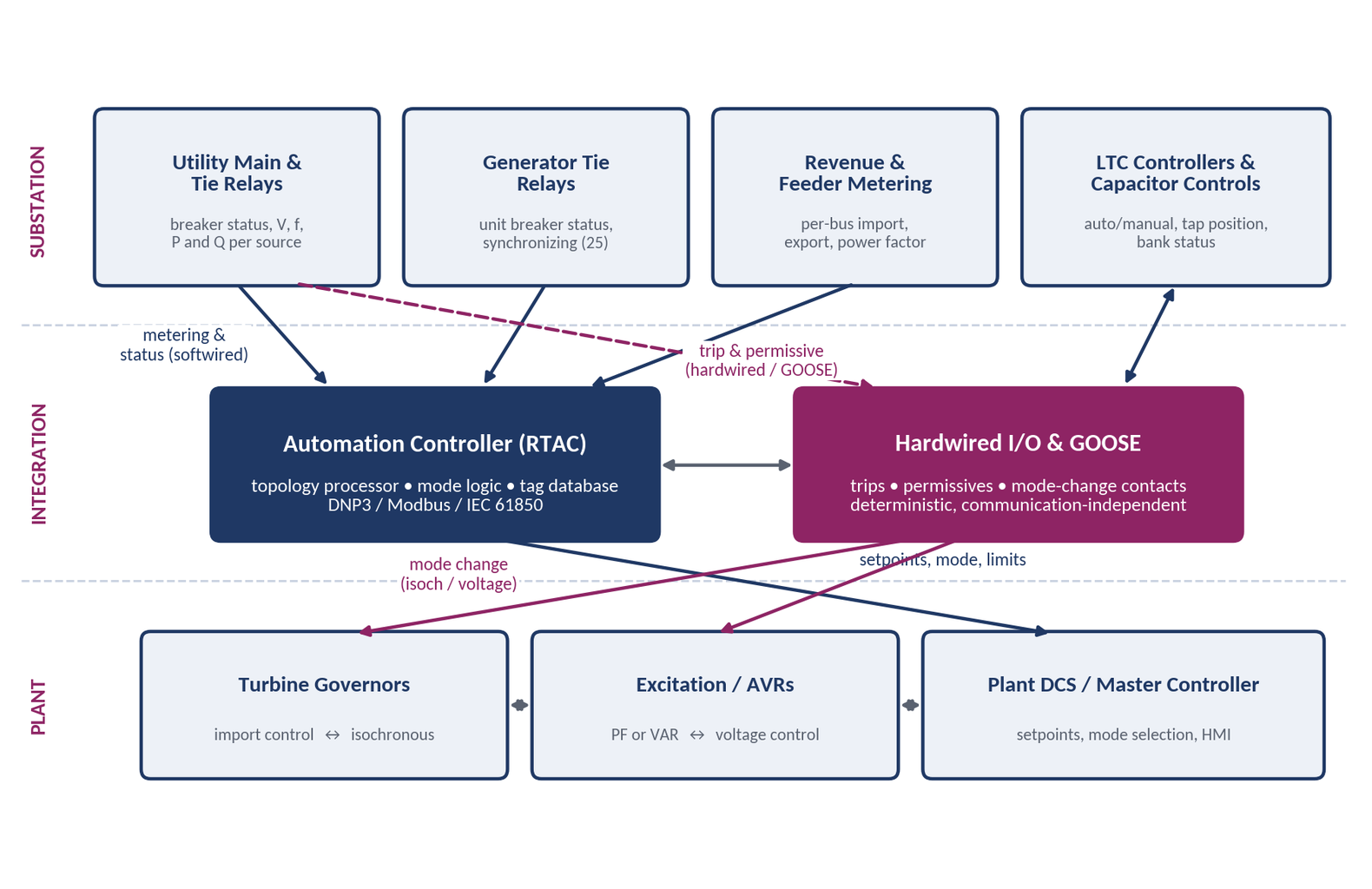
The architecture question that comes up on every one of these projects is which signals should be hardwired and which can be carried over a protocol. The answer follows from consequence, not from convenience.
Figure 1 — Typical three-tier architecture: substation devices, an automation controller with parallel hardwired I/O, and the plant control layer.
| Signal category | Recommended path | Why |
|---|---|---|
| Breaker status used for mode and source-count decisions | Hardwired, mirrored to the automation controller | Mode decisions must remain correct when communications fail |
| Island trip and mode-change commands | Hardwired contacts or IEC 61850 GOOSE | Needs deterministic transfer within milliseconds |
| Close permissives enforcing the source limit | Hardwired | Protects equipment ratings independently of software |
| Per-bus real and reactive power, voltage, frequency | Softwired: relay or meter to controller to plant control | One-second updates are ample for turbine ramp rates; avoids new transducers |
| Import setpoints, mode selection, device status | Softwired | Supervisory data, with quality flags and defined fail-safe states |
| Communication watchdog and health alarms | Both paths | Loss of data must be visible and must drive a safe default |
3.1 The tag database is a deliverable, not an afterthought
Where these projects lose schedule is almost always at the interfaces between the
substation relays, the automation controller, the turbine control systems and the plant control system. Each vendor has its own point naming, scaling and protocol support. The way to keep that from becoming a commissioning problem is to publish a single tag database early and make every party work from it. For each exchanged point it records the tag name, description, protocol and address, data type, scaling and engineering units, deadband, quality handling and the defined fail-safe value.
4. Operating modes
Every plant of this type runs in several distinct configurations, and the control and protection behavior differs in each. Writing them down as an explicit mode matrix, with entry and exit conditions, is what keeps the logic reviewable.
| Mode | Typical condition | Governor | Excitation / AVR | LTC | Capacitor banks |
|---|---|---|---|---|---|
| Normal | Grid-parallel, full complement of units | Import control | PF or VAR control | Blocked on buses with generation | Per site study |
| Reduced / seasonal | Lower site load, fewer units online, ties closed | Import control by group | PF or VAR control | Blocked where generation is present | Per site study |
| Island | Utility source lost on one or more buses | Isochronous, with load sharing if paralleled | Voltage control | Manual or blocked | Tripped and blocked |
| Maintenance | Unit, tie or transformer out of service | Per configuration | Per configuration | Auto when generation is absent | Per configuration |
| Resynchronization | Utility restored, returning to grid-parallel | Ramp to import control | Return to PF or VAR | Return to auto after settling | Reconnect after checks |
5. Island detection: the part that is genuinely hard
5.1 The non-detection zone
When a site separates from the utility, the initial rate of change of frequency is governed by the power mismatch at the moment of separation and the stored rotational energy of the island:
df/dt = f₀ × ΔP / (2 × H × S)
where f₀ is nominal frequency, ΔP is the mismatch, H is the inertia constant of the connected machines and S is their rating. The consequence is straightforward. A site that was importing two percent of its connected generation sees an initial ROCOF of well under a quarter of a hertz per second, against typical ROCOF pickups of half a hertz per second or more. Governor response then closes the gap further, and voltage may barely move at all if the reactive balance happened to be close.
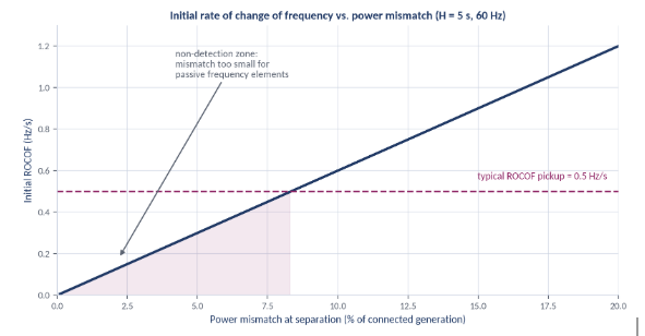
This is the reason a tightly controlled CHP plant cannot rely on under-voltage and under-frequency elements to detect the loss of the grid. Those elements are necessary — they are dependable backup — but they are not sufficient, and any scheme that rests on them alone should be challenged.
5.2 A layered scheme
The design approach we recommend is to provide several independent detection paths, arranged so the fastest and most secure path acts first and the slower paths provide dependable backup.
This is the reason a tightly controlled CHP plant cannot rely on under-voltage and under-frequency elements to detect the loss of the grid. Those elements are necessary — they are dependable backup — but they are not sufficient, and any scheme that rests on them alone should be challenged.
5.2 A layered scheme
The design approach we recommend is to provide several independent detection paths, arranged so the fastest and most secure path acts first and the slower paths provide dependable backup.
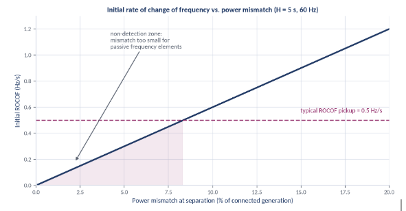
Figure 3 — Layered, bus-selective island detection and the actions it initiates.
- Layer 1 — Direct transfer trip. If the utility can provide a trip signal from the remote line terminals, this is the most secure and fastest indication available, because it reports the actual event rather than inferring it. It is always worth asking for early, since the answer changes the rest of the architecture.
- Layer 2 — Upstream status. Circuit switcher and source breaker positions, combined with loss-of-source logic, cover local openings directly and cheaply.
- Layer 3 — Fast passive elements. Vector shift (78VS) and rate of change of frequency (81R), supervised by voltage and by measured import so they do not operate on large on-site load steps or motor starts.
- Layer 4 — Backup passive elements. Time-delayed under- and over-voltage and under- and over-frequency elements, plus directional power and loss-of-import logic, providing dependable backup inside the required cessation time.
Where synchrophasor measurement is available, comparing the local phase angle against a remote reference provides another independent path that does not depend on the local power balance.
5.3 Separate selectively
Not every loss of a source is an island. In a substation where each bus is fed from two transformers, losing one transformer leaves both of the buses it served still connected to the grid through their other source. No island has formed. What has happened is that the on-site generation can now backfeed a de-energized transformer and the utility line behind it, which is an unacceptable condition for utility personnel and equipment.
The scheme has to distinguish these cases. Loss of a single source should trip only the affected utility connections and leave the buses grid-parallel. A true island — loss of every utility source feeding a bus or a connected group — should trip those sources and assert island mode for that group alone, while other groups continue running grid-parallel.
5.4 How fast is fast enough
Three separate limits apply, and the design must satisfy the most restrictive of them.
- Utility reclosing. Separation must be complete before the utility's reclose dead time expires. An out-of-phase reclose onto an energized island can destroy a turbine-generator, and this is normally the binding constraint.
- Islanding-cessation requirements. Where IEEE 1547 applies, unintentional islanding must cease within two seconds. Whether that standard governs, and which edition, depends on how and at what voltage the plant is connected.
- Site ride-through. The island must form quickly enough that the voltage and frequency excursion stays inside what site processes and motor loads can tolerate.
6. Making the transition seamless
Detecting the island is only the first half. The plant then has to change how it controls itself, within cycles.
- Governor mode. Units move from import or load control to isochronous control. If several units are paralleled inside the island, one runs isochronous and the others follow, or all run with isochronous load sharing. This transfer should be initiated by a hardwired or GOOSE signal, not by a supervisory command.
- Excitation mode. Excitation systems move from power factor or VAR control to voltage control. Left in VAR control inside an island, the machines regulate to a reactive setpoint that no longer has a grid behind it, and island voltage drifts.
- Load shedding. If any credible island configuration leaves generation short of load, under-frequency or status-based load shedding on selected feeders is required. This has to be checked mode by mode, not once for the best case.
- Motor reacceleration. The voltage dip during the transition has to be checked against motor contactor dropout and adjustable-speed drive ride-through, which are often the first things to trip on site.
- Resynchronization. Return to grid-parallel operation is supervised by sync-check (device 25) across the utility connection, with a defined restoration sequence and a deliberate delay after utility voltage returns.
The honest position on the word seamless is that it is a modeling claim before it is a commissioning result. Demonstrating it in advance requires a dynamic or electromagnetic transient simulation of island formation, load rejection and the mode transfer for each credible configuration. Without that study, the first proof anyone has is the first real event.
7. Protection has to be re-examined for island operation
This is the most commonly missed scope item in CHP island projects, and it matters a great deal.
- Fault current collapses. With the utility contribution gone, available fault current is limited to what the on-site machines can supply, and it decays as machine reactance moves from subtransient to synchronous values. Overcurrent elements set for grid-parallel duty may be slow or may not pick up at all.
- The ground source moves. Grounding that was provided by the utility transformer is replaced by the generator neutral grounding resistors, which are typically far more restrictive. Ground overcurrent sensitivity changes completely, and neutral overvoltage may become the practical ground-fault detection method.
- Coordination changes. Time-current coordination that is correct grid-parallel is not automatically correct in an island. Both cases have to be checked.
- Settings groups are the usual answer. Modern microprocessor relays support multiple settings groups. Assigning an island-mode group, switched by the same logic that asserts island mode, is cleaner and more reviewable than trying to find one set of settings that works acceptably in both states.
- Incident energy changes too. Because clearing times change, arc-flash incident energy in island mode can differ substantially from the grid-parallel case. If the site labels equipment for arc flash, both operating states should be evaluated.
8. Voltage control: tap changers, excitation and capacitor banks
8.1 Tap changers and excitation systems regulate the same voltage
A transformer load tap changer in automatic mode and a generator excitation system in voltage-control mode are two independent regulators acting on the same bus. Left alone, they hunt: the excitation system raises output voltage, the tap changer sees high voltage and taps down, the excitation system responds again, and the plant ends up with taps at one end of their range and machines at a reactive limit. There are two standard remedies.
- Block the tap changer. Place the tap changer in manual whenever generation is supplying the bus, and return it to automatic, after a delay and a settling check, when generation is lost. This is straightforward and easy to verify, but it gives up automatic voltage regulation while the plant runs.
- Run the machines in power factor or VAR control. Leave the tap changer in automatic with an extended time delay and let the excitation systems regulate reactive output rather than voltage. This keeps automatic regulation available, at the cost of a scheme that depends on the machines respecting their limiters.
Both are defensible. The right choice depends on the site's reactive requirements at the interconnection, the tap changer controller's capabilities, and how the buses are fed. Where two transformers feed a common bus, circulating-current control between them — master-follower or reactive-current compensation — has to be reviewed as part of the same exercise.
8.2 Capacitor banks need explicit island rules
Many sites simply switch their capacitor banks off by hand whenever the plant runs, which is a reasonable operating practice and a poor substitute for a design. Four issues drive the engineering.
- Overvoltage at light load. A fixed bank that was correctly sized against utility source impedance can push voltage high on a lightly loaded island, where the source impedance is much larger.
- Generator self-excitation. If capacitive reactive supply exceeds what the machines can absorb, voltage can run away. This is the failure mode that justifies tripping banks on island detection rather than merely blocking further switching.
- Harmonic resonance. The parallel resonant frequency between the bank and the source shifts downward as source strength falls. A bank that sits safely between characteristic harmonics grid-parallel can land on one in an island.
- Switching and reclose. Reclosing onto a charged bank produces severe transients, so reconnection must be interlocked on the bank discharge time as well as on voltage and mode.
The usual recommendation is to permit bank operation only while grid-parallel, under reactive or power-factor control with mode permissives, and to trip and block the banks on island detection, allowing reconnection only after the utility is restored, the bus voltage is inside its window, and the discharge time has elapsed.
9. Standards and reference documents
Which documents govern is a site-specific question, and getting it wrong early distorts the whole design. The interconnection agreement is the controlling document; industry standards fill in the method.
| Document | What it covers | Where it applies |
|---|---|---|
| Interconnection agreement | Export limits, protection requirements, trip and reclose coordination, operating obligations | Always controlling; read before any other document |
| Transmission owner and RTO requirements | Protection, ride-through and modeling requirements for transmission-connected generation | Where the plant connects at transmission voltage |
| IEEE 2030.7 and 2030.8 | Specification and testing of microgrid controllers, including transition functions | Useful framework for intentional islanding and mode transitions |
| IEEE C37.95 | Protective relaying of utility-consumer interconnections | Interconnection protection philosophy |
| IEEE C37.102 and C37.106 | AC generator protection and abnormal frequency operating limits | Generator protection and island frequency limits |
| IEEE C37.104 | Automatic reclosing practice | Establishing the separation speed the scheme must achieve |
| IEEE 519 | Harmonic limits and system response | Capacitor bank and resonance evaluation |
| NERC reliability standards | Registration-dependent obligations, including protection and modeling | Only where the facility and its owner are registered |
10. What a complete engineering package contains
A design that can actually be built and commissioned includes all of the following. Packages that stop at a control narrative tend to generate change orders during construction.
- Existing system review — as-built drawings, existing relay settings and logic, and an explicit compliance matrix against the interconnection agreement.
- Control philosophy — import control, mode matrix, island detection and separation, voltage-control coordination, and capacitor bank rules, written so a reviewer can follow the logic without reading relay code.
- Communications architecture and tag database — every exchanged point, with protocol, scaling, deadband, quality handling and fail-safe state.
- Updated one-line diagrams — reflecting new elements, metering and logic.
- Schematics — trip and close circuits, permissives, mode-change circuits and tap-changer blocking.
- Wiring and interconnection diagrams, panel schedules and loop diagrams — at a level a contractor can install from.
- Cable schedules — for new and modified circuits.
- Relay setting files with change logs — in native format, including any island-mode settings group.
- Field implementation and test procedures — point-to-point checks, functional tests, mode-transfer tests, acceptance criteria and a rollback plan.
11. Eight failure modes worth designing against
- Relying on 27 and 81 elements alone. The tighter the load following, the less likely these are to operate. Layer the detection.
- Treating loss of one source as an island. It usually is not. What it is instead is a backfeed path into de-energized utility equipment.
- Leaving island-mode protection settings unexamined. Fault current and the ground source both change. Use a settings group.
- Letting the tap changers and excitation systems both regulate voltage. Pick one regulator per bus per mode, and make the handoff explicit.
- Leaving capacitor banks connected into an island. Overvoltage, self-excitation and resonance all become live risks at once.
- Softwiring a trip. Protection-critical actions belong on hardwired contacts or GOOSE, with defined performance.
- Leaving the source-count limit to operating procedure. Enforce it in logic and in the close circuits.
- Claiming seamless transfer without simulation. If it has not been modeled, the first proof is the first real event.
12. How we approach this work
Keentel Engineering provides protection, control and interconnection engineering for generation and large-load facilities from 4 kV through 765 kV. On CHP and campus microgrid projects, our scope typically runs from the existing-system review and compliance matrix through the control philosophy, island detection design, relay setting development, construction drawings and cable schedules, and on into field implementation and functional testing support. Where the transition behavior has to be proven before commissioning, we add dynamic and electromagnetic transient simulation of island formation, load rejection and mode transfer.
Our work is led by licensed professional engineers, with independent QA/QC review of every deliverable and drawings sealed in the state where the project is built.
Frequently asked questions
Why can't we simply use under-frequency and under-voltage relays to detect an island?
Because a plant that follows load closely is deliberately keeping the power imbalance at the utility connection very small, and that imbalance is exactly what those elements depend on. With a mismatch of a few percent of connected generation, frequency may drift slowly enough that under-frequency elements take many seconds to operate, or never reach pickup once governors respond. Voltage may hardly move at all if the reactive balance happened to be close. Those elements belong in the scheme as dependable backup, but they should not be the primary means of detection.
What is a non-detection zone, in practical terms?
It is the range of pre-separation operating conditions in which your island-detection elements will not operate in the required time. It is not a defect in the relay; it is a consequence of the physics. The useful engineering output is a quantified statement: for this plant, at these load levels and unit combinations, here are the conditions under which passive detection is not dependable, and here is the additional detection path that covers them.
Is direct transfer trip from the utility worth pursuing?
Almost always, yes. It is the only method that reports the actual event instead of inferring it from local measurements, and it is both the fastest and the most secure path available. It requires utility cooperation and a communications channel, so ask early: whether it is available changes how much the rest of the scheme has to carry.
What is the difference between vector shift and ROCOF?
Vector shift detects an abrupt change in the phase angle of the voltage waveform at the moment of separation — the step change that occurs when the load current previously supplied by the utility transfers to the local machines. ROCOF measures how fast frequency is changing afterwards. Vector shift can act faster for a given mismatch, but both depend on the mismatch and both need supervision so they do not operate on large on-site load steps, motor starts or nearby faults.
Does IEEE 1547 apply to our plant?
It depends on how the plant is connected. IEEE 1547 addresses distributed energy resources interconnected with distribution systems. A plant connected through a transmission-voltage substation may instead be governed by the transmission owner's interconnection requirements and the regional transmission organization's rules, sometimes with IEEE 1547 cited in the agreement anyway. The controlling document is the interconnection agreement, and confirming which edition and which requirements it cites should be one of the first tasks in the project.
IEEE 1547 requires unintentional islands to cease within two seconds. How can islanding also be seamless?
The two requirements are compatible, but only if the design is precise about what is being islanded. The requirement is that the plant must stop energizing the utility system. It does not require the site to go dark. If the utility connection opens quickly and cleanly, what remains is an intentional island on the customer side, which is a permitted and planned configuration. What is not permitted is the plant continuing to energize utility conductors while everyone waits to see what happens.
What happens if the utility recloses onto our island?
If the island is still connected and is out of phase, the result can be a severe torsional and electrical shock to the turbine-generators, with damage ranging from shaft fatigue to complete mechanical failure. This is the risk that sets the speed requirement for the whole scheme: separation must be complete before the utility's reclose dead time expires. It is why the utility's reclosing practice and dead times are essential inputs, and why a scheme cannot be designed properly without them.
We lost one utility source but both affected buses are still energized from their other source. Are we islanded?
No. Both buses remain grid-parallel. The real problem in that condition is different: your generation can now backfeed the de-energized transformer and the utility line behind it. That is hazardous for utility personnel and equipment, and it is why the scheme should trip the affected utility connections selectively on loss of a source, rather than either ignoring the condition or islanding the whole site.
Which breaker should trip if we start exporting?
That is a philosophy decision to settle with the owner and the utility, not a default. Tripping the generator tie stops the export while keeping the site connected to the grid, which is usually the less disruptive outcome. Tripping the utility source stops the export by islanding the site, which is a large response to a condition that is not a fault. What should not be in question is that control action, in the form of a generator runback, gets the first opportunity to correct the condition.
Which signals must be hardwired, and which can go over a protocol?
Decide by consequence. Anything whose failure would prevent a trip or allow an unsafe closure — trips, mode-change commands, close permissives, breaker status used in protection logic — should be hardwired or carried over IEC 61850 GOOSE with defined performance. Metering, setpoints, mode selection and status display can be softwired over DNP3 or Modbus, provided every point has quality handling and a defined fail-safe value.
Is one-second metering data fast enough for load following?
Yes, for the control loop. Turbine ramp rates are measured in megawatts per minute, so a one-second update is comfortably faster than the plant can respond. What is not fast enough at one second is anything protective. Do not let an adequate metering update rate become an argument for softwiring a trip.
What happens to our protection settings when we island?
They may no longer work. Available fault current drops to what the local machines can supply and decays as machine reactance rises, so overcurrent elements set against utility fault duty may be slow or may not operate. Separately, the ground source shifts from the utility transformer to the generator neutral grounding resistors, which usually limit ground fault current far more severely, changing ground element sensitivity completely. The standard solution is a dedicated island-mode settings group, switched by the same logic that asserts island mode.
Do we need a separate arc-flash study for island operation?
If the site maintains arc-flash labeling, it is worth evaluating. Incident energy depends on both available fault current and clearing time, and both change in an island. Lower fault current with a longer clearing time can produce higher incident energy than the grid-parallel case, so the conservative label is not always the one you already have.
Why must the tap changers go to manual when the plant is running?
Because a tap changer in automatic and an excitation system in voltage control are two regulators acting on the same bus, and they will fight — taps run to one end of their range while the machines sit at a reactive limit. Blocking the tap changer while generation is present is the simplest way to leave one regulator in charge. The alternative is to leave the tap changer in automatic with an extended delay and run the machines in power factor or VAR control instead.
When should the tap changer return to automatic?
After generation is lost, with a deliberate delay, once bus voltage has settled and the tap position has been checked. Returning immediately after a unit trip risks runaway tapping during the voltage transient that follows.
Can we keep our capacitor banks in service while the plant runs?
Sometimes, while grid-parallel, if the reactive requirements at the interconnection justify it and the machines cannot supply the reactive support more economically. In an island, the answer is normally no: overvoltage at light load, generator self-excitation and shifted harmonic resonance all become live risks. The usual design is to permit operation grid-parallel under reactive control with mode permissives, and to trip and block the banks on island detection.
How many operating modes do we actually need to define?
More than owners typically expect. Beyond the obvious normal, island and maintenance cases, plants need explicitly defined behavior for seasonal or reduced-load operation, for configurations with a transformer out of service, for configurations with a generator tie out of service, and for the resynchronization sequence itself. Each needs entry and exit conditions, permissives and alarms. Modes discovered during commissioning are the ones that produce field changes.
What is a topology processor and why does the controller need one?
It is logic that reads every main, tie and generator breaker position and determines which buses are currently connected to each other. The controller uses it to decide which power measurements to sum, how to allocate setpoints among units, how many sources are paralleled on each group, and which buses are islanded. Without it, the control scheme is only correct for the configuration it was written against, and the first tie closure invalidates it.
Do we need a dynamic or EMT simulation, or is a good design enough?
A good design gets the scheme right in principle. Simulation is what demonstrates, before commissioning, that island formation, load rejection and mode transfer actually behave acceptably for each credible configuration — including the voltage dip that motors and drives will see. If the specification uses the word seamless, or if a failed transition would interrupt a critical process, the study should be in scope. It is also the most efficient way to find the case where the island is short of generation and load shedding is required.
How long does this kind of engineering take?
For the design itself, a realistic range for a complete package — review, control philosophy, island detection design, relay settings, construction drawings, cable schedules and test procedures — is roughly four to eight weeks, driven more by the availability of as-built information and vendor interface data than by the engineering. Compressed schedules are achievable with parallel staffing and daily coordination with the turbine and control vendors, but the dependency on owner and vendor data does not compress. Where a schedule has slipped on these projects, the cause is almost always late drawings, missing relay setting files or an interconnection agreement that nobody has read.
What information do you need from us to start?
As-built substation drawings and any recent issued-for-construction package; existing relay setting files and automation controller project files; the executed interconnection agreement with its protection and operating exhibits; relay, controller and tap-changer models and firmware; the turbine control and plant control platforms and their supported protocols; capacitor bank ratings; generator data including inertia constants and excitation and governor models; neutral grounding resistor ratings; historical load data by bus; and the utility's source impedance, reclosing practice and position on transfer trip.
Can this be done without taking the plant offline?
Much of it can. Design, settings development and drawing production have no operational impact. Implementation normally requires outages, but these can usually be staged bus by bus, and the sequencing should be part of the field implementation procedure rather than something worked out on site. Functional testing of mode transitions and island detection does require planned outage windows, and those windows should be identified early because they are usually the longest-lead item in the schedule.
Talk to us
Keentel Engineering provides
power system studies, protection and control design, interconnection engineering and NERC compliance services for utilities, developers, EPCs and large-load owners nationwide, from our offices in Tampa, Austin, Sacramento and Baltimore. If you are planning a CHP islanding or load-following project and want to talk through the approach, we are happy to have that conversation.

About the Author:
Sandip "Sonny" R. Patel, P.E.
IEEE Senior Member · Founder & CEO, Keentel Engineering
In 1995, Sonny Patel earned his Electrical Engineering degree from the University of Illinois. But degrees don't build legacies — action does.
For three decades, he has worked the power industry from every side of the table: 16 years as a utility engineer at Exelon/Commonwealth Edison; generation leadership across hydroelectric, industrial steam turbine, and a 9 GW renewable fleet; NERC Regional Entity Senior Compliance Engineer and Audit Team Lead, auditing some of the nation's largest utilities; and testing and commissioning lead on equipment up to 765 kV — the very top of the North American grid.Utility. Generator. Regulator. Consultant. Few engineers have seen all four seats. Fewer still have sat in them.
His experience spans nuclear, hydro, conventional generation, renewables, oil and gas, mining — and today's data centers, where he is authoring a three-book series on data center design. He is a Licensed Professional Engineer in six states and a Licensed Electrical Contractor in Florida (Unlimited EC) — he doesn't just design the work; he's qualified to stand behind its execution.Today, as Founder and CEO of Keentel Engineering, Sonny leads a nationwide team of engineers delivering substation design, power system studies, NERC compliance, and commissioning — done right, coast to coast.Three decades. Every side of the table. One standard: accountable engineering.
Services

Let's Discuss Your Project
Let's book a call to discuss your electrical engineering project that we can help you with.
About the Author:
Sandip "Sonny" R. Patel, P.E.
IEEE Senior Member · Founder & CEO, Keentel Engineering
In 1995, Sonny Patel earned his Electrical Engineering degree from the University of Illinois. But degrees don't build legacies — action does.
For three decades, he has worked the power industry from every side of the table: 16 years as a utility engineer at Exelon/Commonwealth Edison; generation leadership across hydroelectric, industrial steam turbine, and a 9 GW renewable fleet; NERC Regional Entity Senior Compliance Engineer and Audit Team Lead, auditing some of the nation's largest utilities; and testing and commissioning lead on equipment up to 765 kV — the very top of the North American grid.
Utility. Generator. Regulator. Consultant. Few engineers have seen all four seats. Fewer still have sat in them.
His experience spans nuclear, hydro, conventional generation, renewables, oil and gas, mining — and today's data centers, where he is authoring a three-book series on data center design. He is a Licensed Professional Engineer in six states and a Licensed Electrical Contractor in Florida (Unlimited EC) — he doesn't just design the work; he's qualified to stand behind its execution.
Today, as Founder and CEO of Keentel Engineering, Sonny leads a nationwide team of engineers delivering substation design, power system studies, NERC compliance, and commissioning — done right, coast to coast.Three decades. Every side of the table. One standard: accountable engineering.
Leave a Comment
Thank you for contacting us.
We will get back to you as soon as possible.
We will get back to you as soon as possible.
Oops, there was an error sending your message.
Please try again later.
Please try again later.
Related Posts
By SANDIP R PATEL
•
September 19, 2026
Explore utility scale solar engineering from site assessment to POI interconnection, including PV design, BESS, substation and grid studies.
By SANDIP R PATEL
•
September 18, 2026
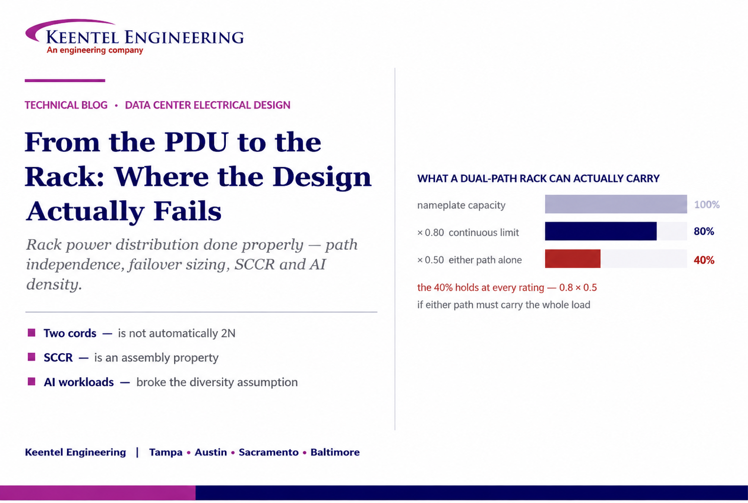
Learn how to size rack power distribution, PDU and RPP systems for continuous loads, A/B redundancy, failover capacity, SCCR and high-density AI data centers.
By SANDIP R PATEL
•
September 18, 2026
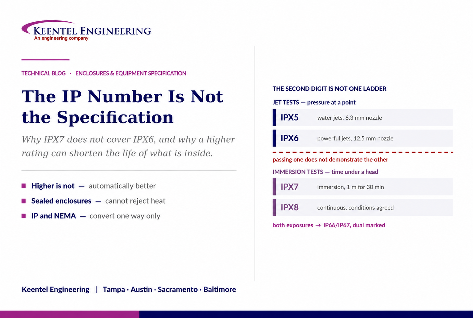
Learn why IP ratings like IP66, IP67, and IP68 do not tell the full story. Understand enclosure selection, NEMA differences, heat, corrosion, and protection.
By SANDIP R PATEL
•
September 9, 2026
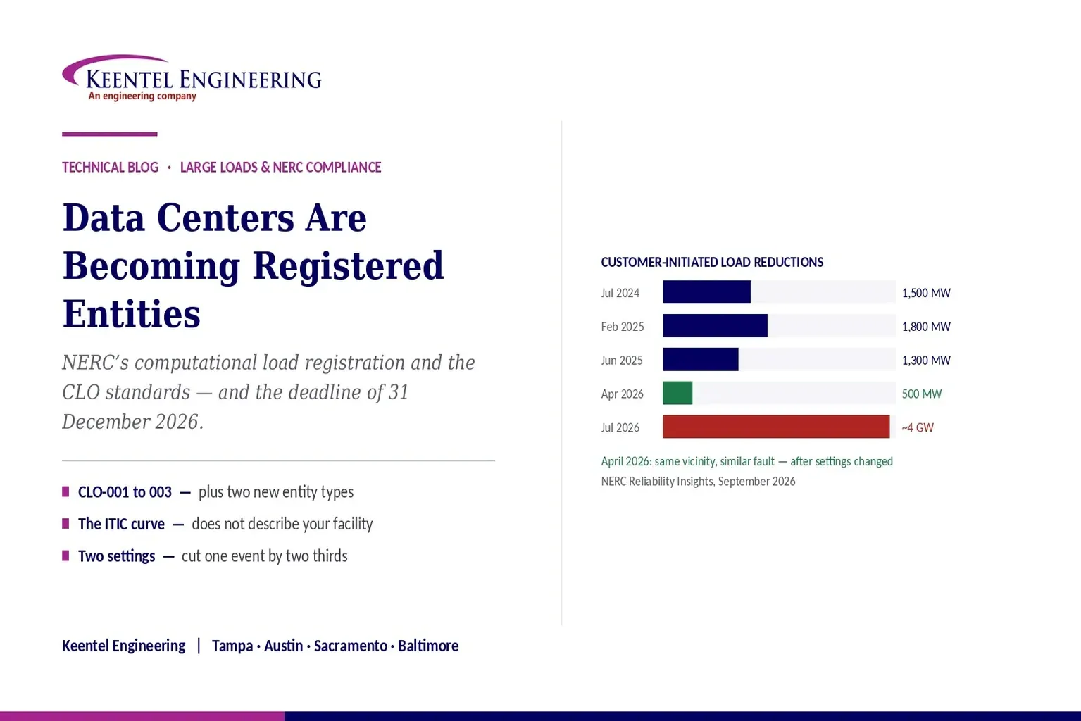
Learn how NERC computational load registration impacts data centers, CLO standards, ride-through requirements, modeling, and grid reliability compliance.
By SANDIP R PATEL
•
September 7, 2026
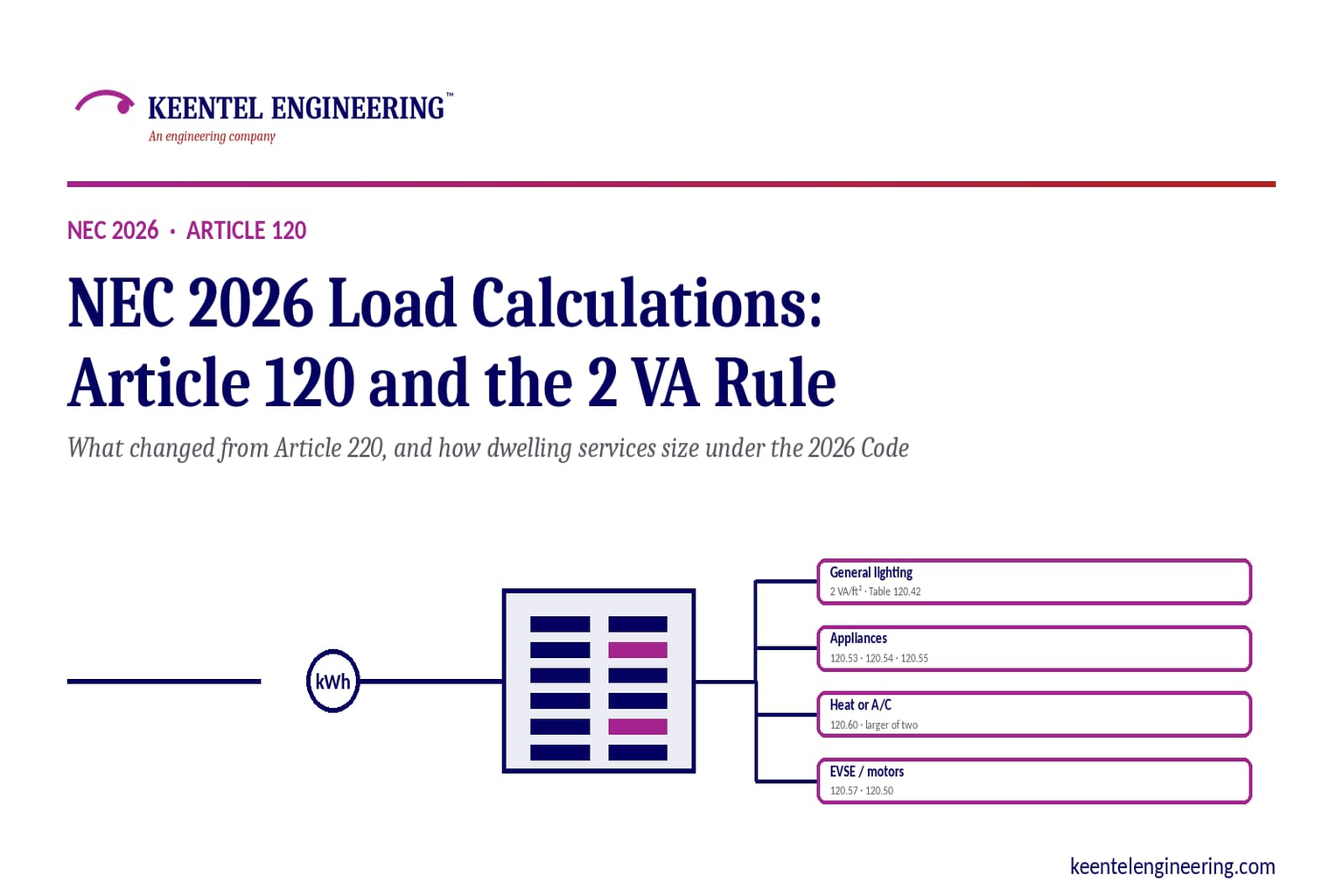
Learn NEC 2026 load calculations, Article 120 changes, the 2 VA rule, EV charging requirements, service sizing, and dwelling calculation methods.
By SANDIP R PATEL
•
September 7, 2026
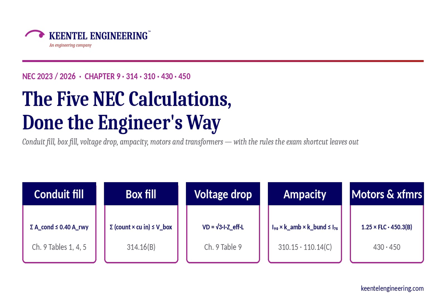
Learn five essential NEC calculations covering conduit fill, voltage drop, ampacity, motor circuits, and transformer protection with engineering examples.
By SANDIP R PATEL
•
September 7, 2026
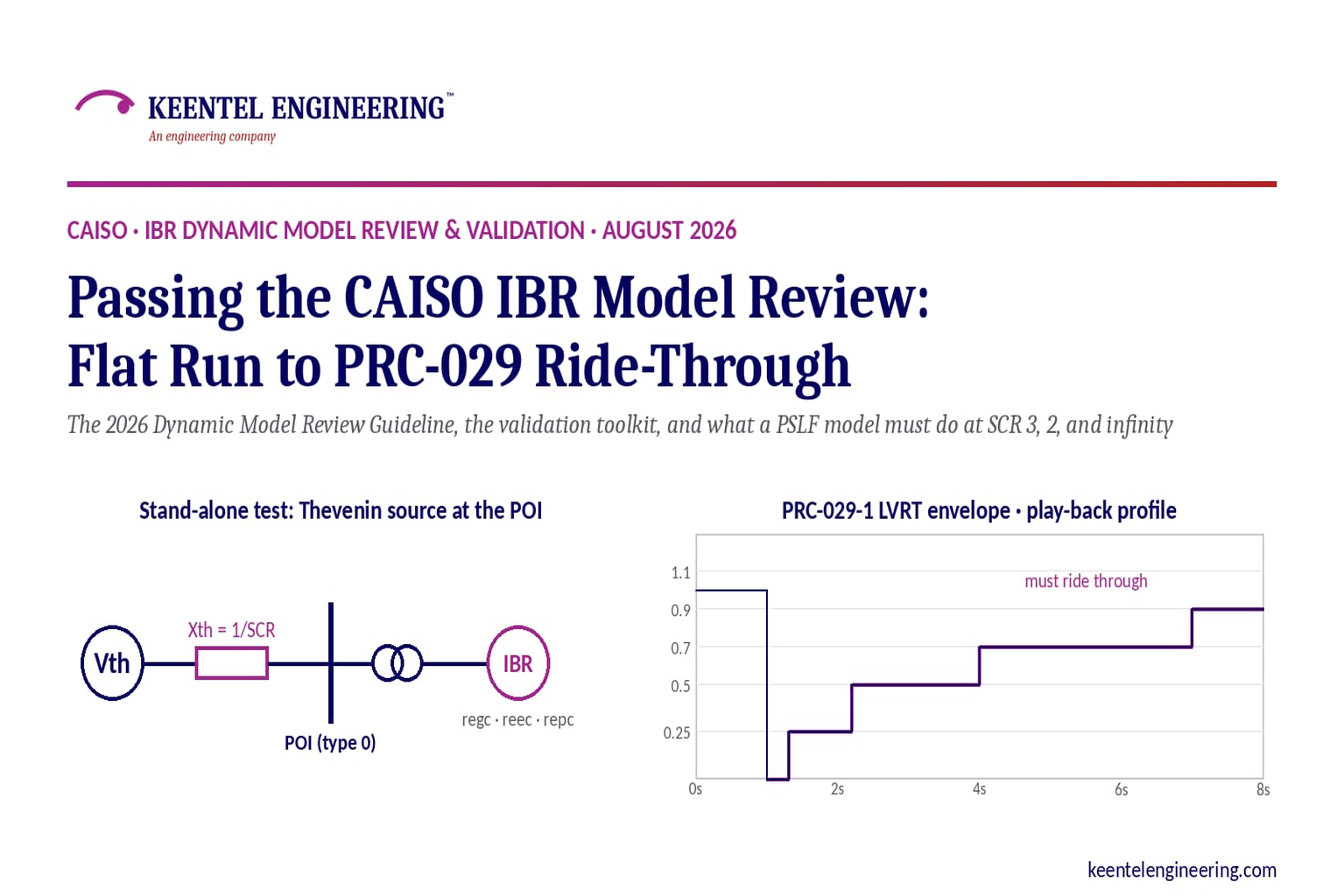
Learn how CAISO reviews IBR models using PSLF validation, PRC-029-1 ride-through requirements, WECC models, and inverter resource compliance testing.
By SANDIP R PATEL
•
September 7, 2026
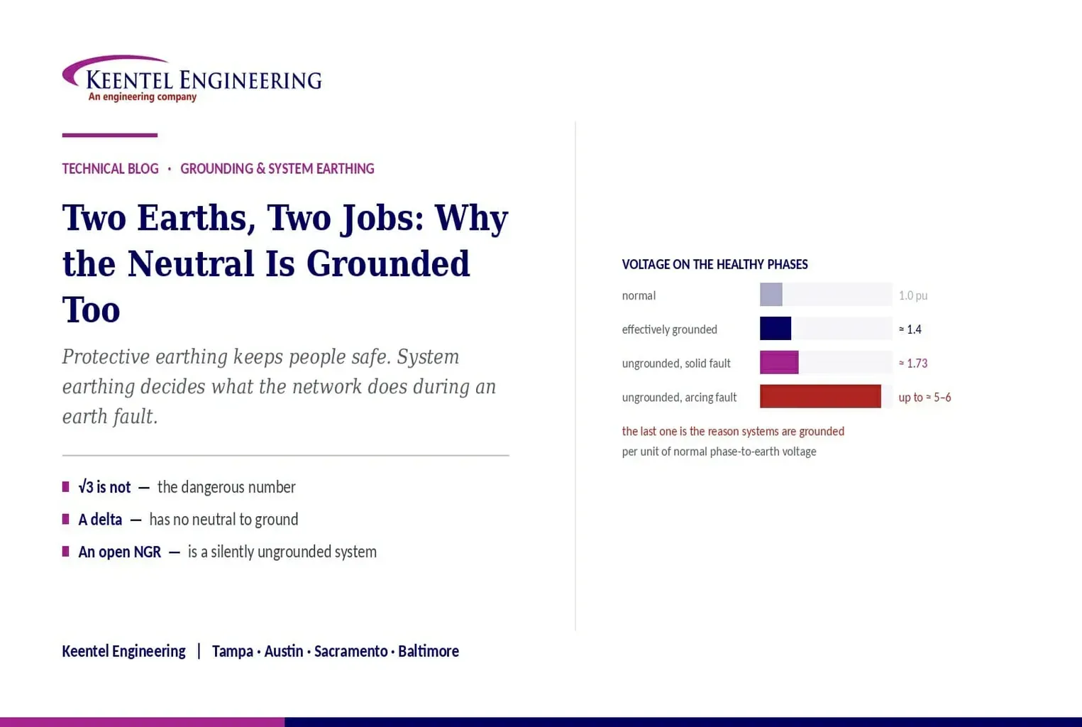
Understand system earthing and protective earthing, neutral grounding methods, effective grounding, ground grids, and insulation coordination for power systems
By SANDIP R PATEL
•
September 6, 2026
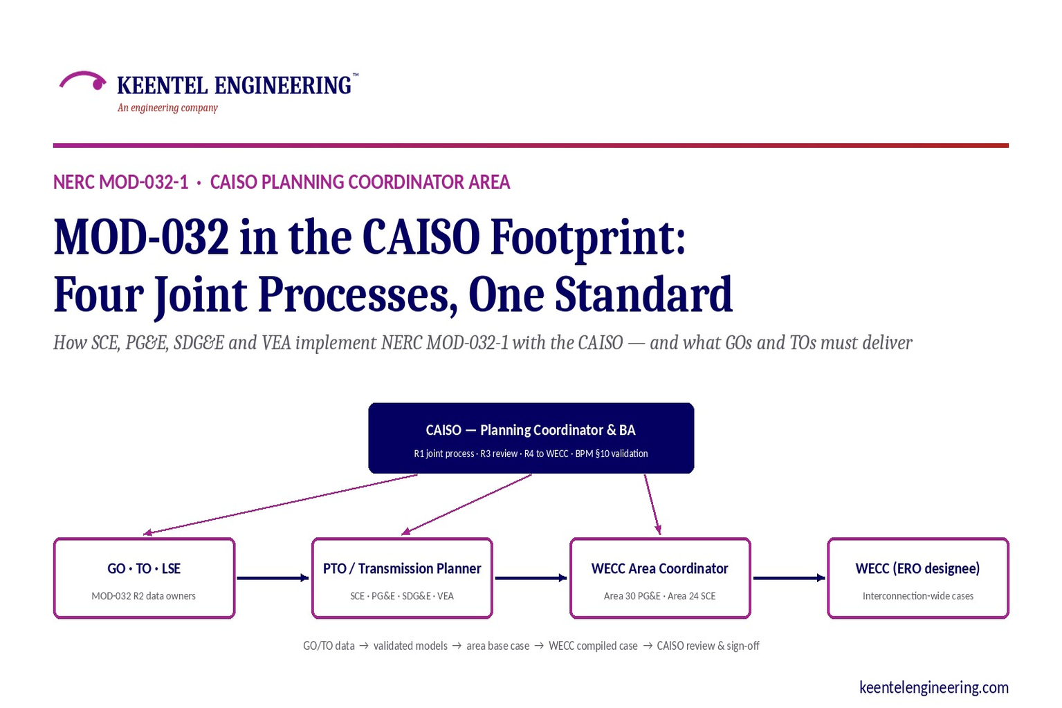
Learn how NERC MOD-032-1 applies across CAISO, SCE, PG&E, VEA and SDG&E, including generator data, PSLF models, EMT requirements and WECC submissions.





