
A Coordinated Electric System Interconnection Review—the utility’s deep-dive on technical and cost impacts of your project.
Challenge: Frequent false tripping using conventional electromechanical relays
Solution: SEL-487E integration with multi-terminal differential protection and dynamic inrush restraint
Result: 90% reduction in false trips, saving over $250,000 in downtime
The three operating regions you have to design to
| Device | Output vs voltage | Response | Best suited to | Main limitations |
|---|---|---|---|---|
| Mechanically switched capacitor or reactor | Proportional to voltage squared | Seconds; discrete steps; limited switching operations per day | Steady-state reactive supply, voltage profile, loss reduction | No dynamic capability; step voltage change on switching; capability collapses when most needed |
| Static var compensator | Capacitive branches proportional to voltage squared | A few cycles; continuously controllable | Continuous control where cost matters and deep voltage support is not the driver | Square-law capability loss; harmonic filters are part of the plant and interact with the network |
| STATCOM | Approximately proportional to voltage — constant current capability | One to two cycles closed loop; converter response faster still | Voltage stability margin, weak interconnections, fast disturbance recovery, flicker and unbalance compensation | Higher capital cost; converter losses; adds a converter and its control dynamics to the network |
| Synchronous condenser | Governed by machine capability and excitation | Excitation response in the hundreds of milliseconds; inherent inertial response instantaneous | System strength and inertia, short-circuit contribution, black start support | Rotating plant with maintenance and losses; slower controlled response than a converter |
| STATCOM with energy storage | Reactive as a STATCOM, plus real power within the storage rating | As STATCOM for reactive; real power limited by storage | Where a real power deficiency is part of the problem | Cost and complexity of the storage; different failure and maintenance profile |
Where Storage Belongs in an 800 VDC AI Data Center

September 26, 2026 | Blog
Eight Orders of Magnitude of Hold-Up Time, Why the Permitted Voltage Swing Decides the Technology, and the Question the Single-Line Never Asks — What Happens When Six Energy Sources Feed One DC Fault
1. Executive Summary
The emerging architecture for AI data centers moves the distribution bus from alternating current at low voltage to direct current at around 800 volts, replaces the conventional transformer and uninterruptible power supply chain with a solid-state transformer feeding that bus directly, and distributes energy storage across several distinct technologies rather than concentrating it in one battery plant.
That last decision is the interesting one, and it is the subject of this paper. A modern AI facility may contain six separate storage assets: hold-up capacitance inside the power electronics, a capacitor backup unit, an optional flywheel, a rack or row-level battery backup unit, an optional direct-current energy storage system on the 800 volt bus, and an alternating-current battery energy storage system at the medium-voltage bus. Each sits at a different electrical node and covers a different span of time.
The principle behind that arrangement different storage, different timescales, the right asset at the right electrical node, architecture before sizing is correct, and this paper does not argue with it. What it does is supply the arithmetic that justifies it, and then raise the questions a storage placement diagram does not answer.
Five findings frame the work.
First, the reason 800 volts direct current arrived is current, not efficiency. A one megawatt rack drawing power at 48 volts would require 20,833 amperes. At 800 volts the same rack draws 1,250 amperes. At a conservative two amperes per square millimetre the copper falls from 10,417 square millimetres per pole to 625 from about 93 kilograms of conductor per metre to under six. Efficiency is a genuine benefit but it is a consequence; the conductor is the reason.
Second, the span of hold-up time the architecture must cover is eight orders of magnitude, and nobody states it. At a one megawatt load, 100 microseconds of ride-through is 100 joules and four hours is 14.4 gigajoules a ratio of 144 million to one. No single storage technology spans that. The six-asset arrangement is not an aesthetic preference; it is forced by physics.
Third, what separates one capacitive technology from another is not capacitance but the permitted voltage swing. Energy stored between two voltages goes as the difference of their squares, so allowing an 800 volt bus to sag to 400 volts rather than to 760 volts reduces the capacitance required for the same energy by a factor of 7.7. That single ratio is why hold-up capacitance inside a converter and a capacitor backup unit on the bus are different assets with different components, and it is the quantitative content behind a phrase like "match the right timescale".
Fourth, the architecture stands up to a check against the disturbance it exists to handle. A 500 kilowatt load step in 10 milliseconds, against an upstream converter able to ramp at 5 megawatts per second, leaves an energy deficit of about 22.5 kilojoules equivalent to 22.5 milliseconds at full load. A capacitor backup unit sized for 100 milliseconds covers it roughly four times over. The placement is correct. The point is that no one can confirm that without running the arithmetic for the actual step.
Fifth, and most importantly, the diagram omits the hardest problem in the whole architecture. Six storage elements connected to one direct-current bus are six fault current sources, and a direct-current system has no natural current zero at which to interrupt. A hold-up capacitance bank of 33 millifarads at five milliohms presents a prospective peak of 160 kiloamperes with a time constant of 0.2 milliseconds. A capacitor backup unit of 0.42 farads at fifty milliohms presents 16 kiloamperes for 21 milliseconds. Batteries and a flywheel contribute on longer timescales again. Protecting that bus means clearing the sum of six contributions with completely different signatures, and that is an engineering problem no storage placement diagram addresses.
The sentence worth taking from this
Deciding where storage sits is the easy half of the architecture, and the half the industry is currently discussing. Deciding what happens when the bus those six sources share develops a fault is the hard half, and it is barely discussed at all.
Architecture first and sizing second is the right instruction. Protection belongs in the first step, not the second.
2. The Architecture Is Right About the Thing That Matters
It is worth being explicit about what the emerging arrangement gets right, because the sections that follow add to it rather than correct it.
The correct principle
The central idea is that energy storage is not a single commodity. A capacitor, a supercapacitor, a flywheel and a lithium battery are not competing solutions to one problem; they are solutions to different problems that happen to share the word "storage". They differ by several orders of magnitude in how much energy they hold per unit mass, and by several more in how quickly they can deliver it.
The architectural consequence follows directly. If the facility must ride through events spanning microseconds to hours, and no single technology spans that range, then the facility needs several technologies, and each should be connected at the electrical node where its particular timescale is useful.
Architecture before sizing
The instruction to settle the architecture before sizing the storage is the right order and it is the one most often reversed. The common failure is to begin with a required minutes-of-autonomy figure inherited from a conventional data center specification, size a battery to it, and then discover that the battery cannot respond to a millisecond load step, cannot be located where it is needed, and does not address the disturbance that actually threatens the equipment.
Starting from the disturbances what events must the facility survive, on what timescale, at what node and only then asking what asset covers each, produces a different and better answer.
Not one mandatory topology
The honesty of stating that no single topology is mandatory deserves acknowledgement, because the alternative claim is commercially attractive and technically false. Open specifications of this kind establish common interfaces so that equipment from different suppliers can be combined; they do not dictate one arrangement. Which of the optional assets a particular facility needs depends on its load profile, its utility supply quality, its generation strategy and its availability target.
That flexibility is a benefit and it transfers responsibility. If the topology is not mandated, then somebody has to decide it, justify it, and take responsibility for the protection and control consequences that follow. That is an engineering scope, and the rest of this paper is about its content.
3. Why 800 VDC: The Current That Made It Inevitable
The move to a higher-voltage direct-current bus is usually explained in terms of efficiency. Efficiency is real, and section 17 quantifies it. But it is not the reason the change is happening. The reason is that rack power has risen to a level at which low-voltage distribution has become physically impossible.
| Rack power | Current at 12 V | Current at 48 V | Current at 400 V | Current at 800 V |
|---|---|---|---|---|
| 15 kW — legacy enterprise | 1,250 A | 312 A | 38 A | 19 A |
| 40 kW — dense enterprise | 3,333 A | 833 A | 100 A | 50 A |
| 120 kW — current AI rack | 10,000 A | 2,500 A | 300 A | 150 A |
| 250 kW — next generation | 20,833 A | 5,208 A | 625 A | 312 A |
| 600 kW | 50,000 A | 12,500 A | 1,500 A | 750 A |
| 1 MW | 83,333 A | 20,833 A | 2,500 A | 1,250 A |
Read the bottom row. A one megawatt rack served at 48 volts requires 20,833 amperes. That is not a busbar problem to be solved with more copper; it is outside the range of practical connectorised distribution at rack scale. At 800 volts the same rack draws 1,250 amperes, which is an ordinary number.
What that does to the conductor
Sizing a rack feed at a conservative two amperes per square millimetre:
| Distribution voltage | Current for 1 MW | Copper per pole | Mass of conductor |
|---|---|---|---|
| 48 V | 20,833 A | 10,417 mm² | 93.3 kg per metre per pole |
| 400 V | 2,500 A | 1,250 mm² | 11.2 kg per metre per pole |
| 800 V | 1,250 A | 625 mm² | 5.6 kg per metre per pole |
The ratio from 48 to 800 volts is 16.7 in current and 278 in resistive loss for a conductor of unchanged cross-section. Put the other way, the same loss is achieved with 1/278th of the copper. On a facility with tens of megawatts of IT load and hundreds of metres of distribution, that is the difference between a buildable design and an unbuildable one.
The design consequence worth carrying
800 VDC was not adopted because it is elegant. It was adopted because rack power outgrew the alternative.
That matters when evaluating claims about the architecture. Its benefits are real, but its adoption is not optional at high rack density, which means the industry will deploy it whether or not the surrounding problems — protection, grounding, arc flash, storage coordination — have been solved. Those problems belong to the designer, and they arrive on the same schedule as the racks.
4. Eight Orders of Magnitude: The Energy Arithmetic
This section supplies the quantitative justification for the multi-asset architecture, which is a calculation any storage placement diagram implies and none of them shows.
Ride-through energy is simply power multiplied by time. For a one megawatt load:
E = P × t
| Hold-up time | Energy required | In watt-hours | Relative to 100 µs | Asset that covers it |
|---|---|---|---|---|
| 100 µs | 100 J | 0.028 Wh | 1× | Hold-up capacitance in the converter |
| 1 ms | 1 kJ | 0.28 Wh | 10× | Hold-up capacitance |
| 10 ms | 10 kJ | 2.8 Wh | 100× | Hold-up capacitance into CBU range |
| 100 ms | 100 kJ | 27.8 Wh | 1,000× | Capacitor backup unit |
| 1 s | 1 MJ | 278 Wh | 10,000× | CBU or flywheel |
| 10 s | 10 MJ | 2.78 kWh | 100,000× | Flywheel or battery backup unit |
| 60 s | 60 MJ | 16.7 kWh | 600,000× | Battery backup unit |
| 5 min | 300 MJ | 83.3 kWh | 3,000,000× | BBU bridging to generator |
| 30 min | 1.8 GJ | 500 kWh | 18,000,000× | DC-coupled energy storage |
| 4 h | 14.4 GJ | 4 MWh | 144,000,000× | AC-coupled BESS |
The final column of the final row is the finding. From the shortest ride-through the power electronics must provide to the longest the facility might want, the energy requirement spans a factor of 144 million.
No storage technology covers that. Capacitors are unbeatable at the top of the table and useless at the bottom. Lithium batteries are the reverse. Between them sit supercapacitors and flywheels, each occupying a band. The six-asset architecture is what that table looks like when it is turned into equipment.
What it weighs
The same table expressed as mass makes the point physically. Using indicative installed specific energies roughly three to five watt-hours per kilogram for capacitor assemblies, about twenty for a flywheel, and 120 to 160 for lithium at the installed level the storage for one megawatt of IT load comes out as follows.
| Asset | Duration | Energy | Indicative mass per MW of IT |
|---|---|---|---|
| Hold-up capacitance | 1 ms | 0.28 Wh | Under 100 g |
| Capacitor backup unit | 100 ms | 27.8 Wh | About 6 kg |
| Flywheel | 10 s | 2.78 kWh | About 140 kg |
| Battery backup unit | 5 min | 83.3 kWh | About 700 kg |
| DC-coupled ESS | 30 min | 500 kWh | About 3.3 tonnes |
| AC-coupled BESS | 4 h | 4 MWh | About 25 tonnes |
Those are order-of-magnitude figures for illustration, not specifications. The pattern is what matters: from under a hundred grams to twenty-five tonnes, per megawatt, for assets that all answer to the word "storage". They cannot be located in the same place, protected the same way, or procured under the same specification.
5. Why the Voltage Swing Decides the Technology
The previous section shows why several technologies are needed. This one explains the specific boundary between the two capacitive assets, which is the part of the architecture most often misread as redundant.
Energy extracted from a capacitance as its voltage falls from one level to another is:
E = ½ C ( V₁² − V₂² ) so C = 2E / ( V₁² − V₂² )
The consequence is that the usable energy depends not on the voltage but on the difference of the squares of the start and end voltages. How far the bus is allowed to sag therefore dominates the sizing.
| Hold-up at 1 MW | Energy | C for 800 → 760 V | C for 800 → 700 V | C for 800 → 400 V |
|---|---|---|---|---|
| 100 µs | 100 J | 3.2 mF | 1.3 mF | 0.42 mF |
| 1 ms | 1 kJ | 32 mF | 13.3 mF | 4.2 mF |
| 10 ms | 10 kJ | 0.32 F | 0.13 F | 42 mF |
| 100 ms | 100 kJ | 3.2 F | 1.3 F | 0.42 F |
| 1 s | 1 MJ | 32 F | 13.3 F | 4.2 F |
Compare the last two columns of any row. Allowing the bus to fall to half voltage rather than to 95 per cent of it reduces the required capacitance by a factor of 7.7, for exactly the same delivered energy.
Which is why they are two different assets
That factor is the entire reason hold-up capacitance and a capacitor backup unit are separate things rather than one thing in two sizes.
| Hold-up capacitance | Capacitor backup unit | |
|---|---|---|
| Location | Inside the converter, on the DC link | On the bus, as a distinct assembly |
| Technology | Film or electrolytic | Supercapacitor, often with a DC-DC stage |
| Permitted voltage swing | A few per cent — downstream electronics must keep regulating | Down to half voltage or below, because a converter re-regulates the output |
| Energy per unit capacitance | Low, because the swing is small | High, because the swing is large |
| Timescale served | Microseconds to a few milliseconds | Milliseconds to seconds |
| What it is really for | Keeping the converter's own control loop stable | Covering a load step the upstream source cannot follow |
A supercapacitor bank connected directly across a bus that may only sag five per cent would be enormously oversized, because 95 per cent of its stored energy would be inaccessible. It is the interposing converter permitting the deep swing and re-regulating the output that makes the capacitor backup unit worth building. The converter is not an implementation detail; it is the thing that unlocks the factor of 7.7.
6. The AI Load Step: The Disturbance Behind the Architecture
The architecture exists because AI training workloads present a load profile that conventional data center power systems were not designed for, and it is worth being precise about what that profile is.
Why the load steps at all
A large training job runs synchronously. Thousands of accelerators execute the same sequence of forward pass, backward pass and gradient exchange, in lockstep, coordinated by collective communication operations. During computation they draw close to full power. During the communication phases, and at checkpoint boundaries, they draw substantially less. Because the cluster is synchronised by design, those transitions happen across the whole cluster at once.
The result is a load that swings by a large fraction of its maximum, with transition times measured in milliseconds and repetition periods that can land anywhere from a fraction of a second to many seconds. Reported behaviour varies widely with workload and with the mitigations applied at the accelerator and cluster level, so specific figures should be taken from the actual deployment rather than from any general source, including this one. What is not in dispute is the shape: large, fast, synchronised and repetitive.
Checking the architecture against it
Take a representative case and test whether the capacitor backup unit is placed correctly. A one megawatt cluster steps by 500 kilowatts in 10 milliseconds. The upstream converter can ramp at five megawatts per second, which is fast for a medium-voltage interface.
| Quantity | Value | Comment |
|---|---|---|
| Load step | 500 kW in 10 ms | A load ramp rate of 50 MW/s |
| Source ramp capability | 5 MW/s | Ten times slower than the load |
| Time for source to catch up | 100 ms | Set by the ramp rate, not the step size |
| Deficit during the load ramp | 2.25 kJ | Area between the two ramps |
| Deficit while the source catches up | 20.25 kJ | The larger part, and the one usually missed |
| Total energy from local storage | 22.5 kJ | Equivalent to 22.5 ms at full load |
| CBU sized for 100 ms at 800 → 400 V | 0.42 F, 100 kJ usable | Covers the step about four times over |
The architecture passes. A capacitor backup unit sized on a round hundred milliseconds of full load has ample margin for a step of this severity, which confirms that the asset is at the right node covering the right timescale.
Two observations follow, and both are more useful than the pass itself. The larger part of the energy is consumed not during the load step but during the hundred milliseconds afterwards while the upstream source ramps so the binding parameter is the source ramp rate, not the step rise time. And none of this can be asserted without doing the calculation for the actual workload, the actual converter and the actual step; the same architecture with a slower source or a larger step produces a different answer.
The number to ask a vendor for
Not the converter efficiency, and not the storage energy. The ramp rate, in megawatts per second, that the upstream source can actually follow — and the load step, in megawatts and milliseconds, that the compute platform will actually present.
Those two numbers size the intermediate storage. Everything else is downstream of them.
7. DC-Link and Hold-Up Capacitance
The first storage element is the one nobody procures separately, because it arrives inside the power electronics. It is worth understanding because its limits determine what the next element upstream must do.
What it does
Every switching converter has capacitance on its direct-current link. Its primary job is not ride-through at all it is to provide a low-impedance path for the switching-frequency current, to hold the link voltage stable between switching events, and to keep the converter's control loop in a region where it behaves. Ride-through is a secondary property that falls out of the same component.
- Immediate voltage support on the timescale of the switching period, typically tens of microseconds.
- Suppression of fast transients, including those arriving from the bus and those generated by the load.
- A few hundred microseconds to a few milliseconds of energy, depending on how much voltage droop the downstream regulation tolerates.
Its limits
The constraint is the one from section 5. Because the downstream stage must keep regulating throughout, the permitted droop is small typically a few per cent so only a few per cent of the stored energy is accessible. That is why hold-up capacitance is measured in milliseconds and never in seconds, regardless of how physically large the bank is.
The second constraint is lifetime. Electrolytic capacitors age, and their equivalent series resistance rises with temperature and ripple current until the component no longer performs its primary function. In a facility where the load presents large repetitive current swings, that ageing is accelerated by exactly the workload the facility exists to run. Film capacitors behave better and cost more. This is a maintenance and monitoring consideration that belongs in the design, not a component selection to be left entirely to the equipment supplier.
8. Capacitor Backup Units
The capacitor backup unit is the asset that most distinguishes an AI data center power architecture from a conventional one, because it exists to solve a problem conventional facilities do not have.
What it covers
- High peak power for short periods, without the cycle life penalty a battery would incur.
- AI load steps, in the sense established in section 6 — supplying the deficit while the upstream source ramps.
- Ride-through of short disturbances, including voltage sags on the incoming supply that clear within a few cycles.
Why a capacitor and not a battery
Three reasons, and only the first is obvious.
Power density. A supercapacitor delivers its stored energy in seconds or less; a battery sized for the same peak power would be sized by power rather than by energy, and would therefore be far larger than its energy duty requires.
Cycle life. If the load steps every few seconds during a training run, a battery performing that duty accumulates cycles at a rate that no lithium chemistry tolerates economically. Supercapacitors are effectively indifferent to cycling, which is the property that matters most here and the one most often left out of the comparison.
Response time. A supercapacitor bank with a properly designed converter responds within a switching period. A battery management system has detection and enable delays that are small in absolute terms and large relative to a ten millisecond step.
The duty that sizes it
A capacitor backup unit is not sized by ride-through minutes. It is sized by the largest credible load step and the ramp rate of the source behind it, as computed in section 6 — and then checked against the sag ride-through requirement, which is usually the smaller of the two.
Specifying it in minutes of autonomy, as a conventional UPS would be specified, produces a result that is simultaneously oversized for energy and unverified for the duty it actually performs.
9. Flywheels: High Power, Short Duration, Long Life
The flywheel is shown as optional in most versions of this architecture, and optional is the right classification. It occupies a genuine band between the capacitor backup unit and the battery, and whether that band needs filling depends on the facility.
| Property | Flywheel | Compared with a capacitor bank | Compared with a battery |
|---|---|---|---|
| Energy per unit mass | About 20 Wh/kg installed | Several times higher | Roughly one sixth to one eighth |
| Timescale | Seconds to tens of seconds | Longer | Shorter |
| Cycle life | Effectively unlimited for this duty | Comparable | Far better |
| Response | Fast, limited by its converter | Slightly slower | Faster |
| Degradation with age | Mechanical, predictable, inspectable | Different failure mode | No capacity fade |
| Temperature sensitivity | Low | Comparable | Much lower |
| Standing loss | Continuous, from bearing and windage | Higher than a capacitor | Higher than a battery |
| Maintenance | Rotating plant, with its own programme | More than a capacitor | Different, not necessarily more |
The case for a flywheel rests on cycle life and predictability rather than on energy. In a facility whose load steps continuously, an asset that does not care how many times it is cycled and whose degradation is mechanical and inspectable has real value. The case against rests on standing loss, on the maintenance programme rotating plant requires, and on the fact that a well-designed capacitor and battery pair may leave no gap for it to fill.
Deciding this is a study, not a preference. The input is the actual distribution of event durations the facility will see; the output is whether there is a band between the capacitor and the battery that is both frequently occupied and poorly served.
10. Battery Backup Units and the Generator Sequence
The battery backup unit is the asset with the clearest and most conventional duty: hold the load up until another source of power is available. What has changed is where it sits and what it is sized against.
The duty
- Sustained ride-through of a genuine loss of supply, rather than of a transient.
- Covering upstream interruptions long enough for an alternative source to be established.
- Supporting transfer events, including the open transition interval of a transfer switch.
- Bridging generator start, which is the duty that usually sizes it.
Sizing against the generator sequence
The bridging duty is a sequence of intervals, and it is worth setting them out because the total is routinely underestimated.
| Step | Indicative time | Note |
|---|---|---|
| Utility loss detected and confirmed | 0.1 s | Detection must be secure against transients |
| Generator crank and start | 5 – 10 s | Depends on machine and starting system |
| Generator reaches rated speed and voltage | 10 – 15 s | Cumulative from start |
| Transfer switch operates | 0.1 – 1 s | Open or closed transition |
| Load accepted, in blocks | 15 – 30 s total | Block loading limits step size on the machine |
At one megawatt of IT load, a bridging requirement of thirty seconds with a margin applied gives:
| Margin applied | Hold-up | Energy at 1 MW |
|---|---|---|
| 1.5× | 45 s | 12.5 kWh |
| 2.0× | 60 s | 16.7 kWh |
| 3.0× | 90 s | 25.0 kWh |
Those figures are far smaller than the several minutes a conventional data center battery plant is often specified for, which is the point. Once storage is distributed by timescale, the battery is sized for the job it actually does rather than for an inherited autonomy figure and the result is a smaller lithium inventory inside the building, which has consequences for fire protection, for floor loading and for insurance that all run in the right direction.
What sizing it correctly requires
A defensible battery backup unit sizing needs the generator starting sequence measured rather than assumed, the block loading profile of the machine, the transfer scheme, the end-of-life capacity rather than the beginning-of-life rating, the temperature at which the cells will actually operate, and a decision about whether the unit must also cover a failed generator start and a second attempt. Most of those are site-specific and none is available from a component datasheet.
11. DC-Coupled Storage on the 800 V Bus
Direct-current coupled energy storage connected to the 800 volt bus is shown as optional, and it is the asset whose case is most dependent on what else the facility is trying to do.
The advantage
Its advantage is conversion count. Storage connected to the direct-current bus exchanges energy with the load through one conversion stage. The same storage connected on the alternating-current side must be inverted to AC, transformed, and then rectified again by the solid-state transformer before it reaches the same load. Each stage costs efficiency and adds equipment.
For duties where the energy is destined for the IT load longer-duration buffering, load smoothing, additional resilience the direct-current connection is the more efficient one, and the advantage grows with how often the asset cycles.
The complications
- It adds a large, low-impedance energy source to the direct-current bus, which is a protection problem rather than a nuisance. Section 14 covers this.
- It places lithium inventory inside or adjacent to the technical space, with the fire protection and code consequences discussed in section 18.
- It cannot provide grid services. Energy on the direct-current bus can only reach the utility through the solid-state transformer, and whether that path is bidirectional is an architectural decision with interconnection consequences.
- It must coordinate with every other source on the same bus — a control problem, covered in section 13.
When it is worth it
The direct-current coupled asset earns its place where the facility has a genuine requirement for minutes to tens of minutes of full-load support that is not better met by the generator plant, where a future direct-current microgrid is a real intention rather than a slide, or where on-site generation and storage are being combined to manage a constrained utility supply. Where the requirement is simply "more autonomy", an alternating-current connected system at the medium-voltage bus is usually the better answer, for the reasons in the next section.
12. AC-Coupled BESS: The Only One That Talks to the Grid
The alternating-current coupled battery energy storage system sits at the medium-voltage bus, alongside any on-site generation, and it is categorically different from the other five assets. All of them exist to serve the load. This one can also serve the grid, and that changes what it is.
What it does
| Function | What it means | Who benefits |
|---|---|---|
| Peak management | Limiting the facility's demand at the meter | The facility, through demand charges and connection capacity |
| Energy shifting | Charging when energy is cheap or clean, discharging when it is not | The facility, and the system |
| Grid services | Frequency response, reserves, or whatever the market defines | The system, with revenue to the facility |
| Microgrid support | Holding the site up with on-site generation, islanded from the utility | The facility |
| System stability | Voltage support and, with grid-forming control, inertia and strength | The system |
| Longer-duration balancing | Hours of energy for whatever purpose the operating strategy defines | Both |
The consequence nobody plans for
An alternating-current connected storage system of any size, at a facility with a medium-voltage interconnection, is a generating resource in the eyes of the interconnection process. That has a set of consequences that arrive whether or not the project team expected them.
- An interconnection request, and the study process that goes with it, if the asset can export or if its presence changes the facility's interconnection characteristics.
- Compliance with the applicable interconnection standard for the voltage level and jurisdiction, with the performance requirements that implies.
- Potential registration obligations, depending on size and on the market, with the continuing reliability standard compliance that follows.
- Protection coordination with the utility, including anti-islanding or a deliberate islanding scheme, and the fault contribution the asset adds.
- Power quality obligations at the point of common coupling, since a large inverter-based resource has a harmonic signature.
This is the single most underestimated item in an AI data center electrical scope. A storage placement diagram shows an alternating-current battery next to a substation as though it were another piece of equipment. Depending on its rating and its operating mode, it is a generator interconnection project running in parallel with the data center project, on a longer schedule, with a different counterparty.
The question to settle early
Will the alternating-current storage ever export to the utility, or provide a service the utility pays for?
If yes, the interconnection process starts now and belongs on the critical path. If no, that restriction has to be engineered and demonstrated, not merely stated in an operating procedure — and the utility will want to see how.
13. The Handoff Problem: Bandwidth, Not Just Energy
A diagram showing six storage assets arranged along a timescale axis implies a smooth relay, each asset handing off to the next as the event lengthens. Nothing in the physical arrangement produces that behaviour. It has to be engineered, and it is a control problem rather than an energy problem.
Why energy sizing is not sufficient
An asset can only cover the band it is nominally assigned if it can respond within that band. A battery backup unit rated for minutes is irrelevant to a two millisecond transient no matter how much energy it holds, if its detection and enable sequence takes twenty milliseconds. The sizing table says the band is covered; the control system determines whether it actually is.
The consequence is that every boundary in the timescale chain is a crossover that must be verified. The capacitor bank must still be supporting the bus when the flywheel converter reaches full output. The flywheel must still be delivering when the battery takes over. If any crossover has a gap, the bus voltage falls into it, and the facility discovers the gap during an event rather than during design.
Who is in charge
With six sources on or around one bus, something has to arbitrate. The realistic options are few and they have different properties.
| Scheme | How it works | Strength | Weakness |
|---|---|---|---|
| Voltage droop | Each source responds to bus voltage with its own droop characteristic; no communication | Fast, robust, no single point of failure, inherently stable if set correctly | Sharing is only as good as the droop settings; no explicit priority |
| Hierarchical control | A supervisory controller dispatches sources by priority and state of charge | Explicit priority, state-of-charge management, optimisation possible | Communication latency; the controller is a single point of failure |
| Hybrid | Droop for the fast response, supervisory control for dispatch and recovery | Fast where speed matters, managed where management matters | Two systems to design, tune and verify; interaction between layers |
The hybrid arrangement is the one most real facilities converge on, and it carries the obligation that goes with any two-layer control system: the interaction between the layers must be studied rather than assumed. Sources with independently sensible settings can interact badly, and the failure appears as oscillation on the bus at a frequency nobody designed for.
This is precisely the kind of question that electromagnetic transient simulation exists to answer, and it should be answered before the equipment is ordered rather than during commissioning.
14. Every Storage Element Is a Fault Current Source
This is the most important section in this paper, because it covers the problem the architecture creates and the storage placement discussion entirely omits.
A diagram showing six storage assets feeding one direct-current bus is, read another way, a diagram of six fault current sources connected in parallel. What happens when that bus faults is the defining engineering question of the whole architecture, and it is much harder than the equivalent question on an alternating-current system.
Why direct current is different
An alternating-current fault current crosses zero twice per cycle, and every alternating-current interrupting device is designed around that fact: the arc is extinguished at a natural current zero and the device then withstands the recovery voltage. A direct-current fault current has no natural zero. The interrupting device must force the current to zero itself, against the inductance of the circuit, and absorb the energy stored in that inductance while doing so.
That is a fundamentally different and more demanding duty, and it is why direct-current protection at these power levels relies on solid-state or hybrid devices, current-limiting strategies, and fault-tolerant converter control rather than on conventional breakers.
What each source contributes
The contributions have completely different magnitudes and time signatures, which is what makes coordination difficult.
| Source | Illustrative parameters | Prospective peak | Time signature | Energy available |
|---|---|---|---|---|
| Hold-up capacitance | 33 mF, 5 mΩ ESR | About 160 kA | Decays with a 0.2 ms time constant | 10.6 kJ |
| Capacitor backup unit | 0.42 F, 50 mΩ ESR | About 16 kA | Decays with a 21 ms time constant | 133 kJ |
| Flywheel | Through its converter | Converter-limited | Until the converter blocks, then decaying | Seconds of stored energy |
| Battery backup unit | Cell impedance and BMS limits | Chemistry dependent, often several times rated current | Sustained until the BMS acts | Minutes of energy |
| DC-coupled ESS | As above, at larger scale | Larger again | Sustained | Tens of minutes |
| Solid-state transformer | Converter current limit | Limited by control, if the control survives | Until it blocks | Unlimited while connected |
The capacitive figures deserve emphasis because they are the ones that surprise people. A 33 millifarad hold-up bank with five milliohms of series resistance presents a prospective peak of 160 kiloamperes. It decays quickly the time constant is 0.2 milliseconds but the peak is real and the total stored energy is over ten kilojoules. The capacitor backup unit presents a lower peak of around 16 kiloamperes and sustains it far longer, with 133 kilojoules available.
Neither of those sources is a battery, neither appears on a conventional short-circuit study, and both are physically located close to the equipment they would damage.
Why clearing time dominates everything
The thermal damage a fault does goes as the square of the current multiplied by the time it persists. On the capacitor backup unit contribution alone:
| Clearing time | I²t at about 16 kA | Relative to 1 ms |
|---|---|---|
| 1 ms | 2.6 × 10⁵ A²s | 1× |
| 5 ms | 1.3 × 10⁶ A²s | 5× |
| 10 ms | 2.6 × 10⁶ A²s | 10× |
| 50 ms | 1.3 × 10⁷ A²s | 50× |
Fifty milliseconds is a respectable clearing time on an alternating-current system and it is three cycles. On this bus it is fifty times the damage of a one millisecond clearance. That ratio is why solid-state protection, which can interrupt in tens of microseconds, is not a luxury in this architecture but the enabling technology for it.
The study that has to exist
A direct-current short-circuit study that sums all six contributions, with their individual time signatures, at every point on the bus and a protection scheme that clears the sum, selectively, before any of it does damage.
It is not a conventional short-circuit study with different numbers. Capacitive contributions decaying in microseconds, battery contributions sustained for seconds, and converter contributions that depend on whether the control survives the event are different problems, and a study that treats them alike will be wrong in both directions at once.
15. DC Protection, Grounding and Arc Flash at 800 V
Section 14 establishes the fault duty. This section covers the three consequences that follow from it, each of which is an open design decision rather than a solved problem.
Interruption
The realistic options for interrupting a fault on a bus of this character are a solid-state circuit breaker, which interrupts in tens of microseconds at the cost of continuous conduction loss; a hybrid breaker, which conducts through a mechanical path and commutates to a semiconductor path to interrupt; a fuse, which is simple and fast but not resettable and difficult to coordinate against capacitive contributions; and converter-based current limiting, in which the converters themselves detect and limit rather than relying on a series device.
Each has different selectivity behaviour, and selectivity is the harder half. On a bus with six sources, achieving discrimination so that a fault on one branch does not disconnect the whole bus requires either time grading that the damage arithmetic above makes very difficult, or current grading, or a communicating scheme with its own latency and failure modes.
Grounding
Whether the 800 volt system is ungrounded, solidly grounded, or grounded at its mid-point is a first-order decision that affects touch voltage, fault detection, insulation coordination and equipment specification, and it is almost never shown on an architecture diagram.
| Arrangement | Voltage to earth | First fault behaviour | Principal consideration |
|---|---|---|---|
| Ungrounded (isolated) | Undefined, capacitively determined | No fault current; system continues to operate | Requires insulation monitoring; a second fault is a short circuit; voltage to earth is not controlled |
| Mid-point grounded | ±400 V | Fault current flows; detectable and clearable | Halves the voltage stress to earth; requires a defined mid-point and its own protection |
| Solidly grounded at one pole | 0 and 800 V | Fault on the live pole is a full short circuit | Simple detection; full voltage to earth on one pole |
Mid-point grounding is the arrangement most commonly adopted at this voltage, because halving the voltage to earth materially improves the insulation and touch-safety position while retaining detectable fault current. It is not automatic, it has to be engineered, and the choice interacts with the protection scheme and with the equipment the suppliers have available.
Arc flash
Direct-current arc flash is a real hazard at 800 volts and the analytical position is weaker than for alternating current. The widely used alternating-current arc flash calculation standard does not cover direct-current systems; methods for direct current exist in the literature and in informative material, but they are less mature and less validated at these fault levels.
The practical consequences are that incident energy must still be assessed by a defensible method and documented, that labelling and personal protective equipment requirements follow from it, that the energy available from local capacitance is part of the exposure, and that maintenance procedures must account for stored energy that persists after the source is disconnected. A capacitor bank holding 133 kilojoules is dangerous after isolation, and discharge and verification before work is a procedural requirement rather than a good practice.
16. Redundancy: The Transformer Is Drawn Once
Architecture diagrams show one solid-state transformer between the medium-voltage bus and the 800 volt bus. Real facilities cannot be built that way, and how the redundancy is arranged changes the storage architecture.
The question the single line raises
A solid-state transformer is a power electronic converter. It has a failure rate, it has firmware, and it requires maintenance that takes it out of service. Whatever availability target the facility carries has to survive that, which means at minimum an N+1 arrangement and, for higher targets, fully independent paths.
That decision propagates immediately into the storage architecture, because it determines what the 800 volt bus actually is.
| Bus arrangement | What it implies for storage | Protection consequence |
|---|---|---|
| Single bus, N+1 converters | Storage connects once and serves everything | Any bus fault affects the whole block; selectivity is critical |
| Dual independent buses (2N) | Storage must be duplicated, or shared through a tie with its own protection | A fault is contained to one bus, but a tie creates a path between them |
| Segmented bus with ties | Storage can be distributed by segment | Tie protection and the sequence of operations become the design |
| Per-row or per-pod buses | Storage distributed, smaller per unit, more units | Smaller fault duty per bus, more protection devices to coordinate |
None of these is right in the abstract. The point is that the storage placement question cannot be settled before the bus architecture is, because the same six assets connect differently in each case, and the fault duty each must survive differs by a large factor.
This is what "architecture first, sizing second" means when taken seriously. The architecture in question is not just where the storage sits it is the topology of the bus, its redundancy, its segmentation and its protection. Storage placement is downstream of all of it.
17. The Efficiency Case, Quantified
Efficiency is not the reason for the architecture, but it is a substantial benefit and it is worth computing rather than asserting.
The comparison is between conversion chains. A conventional arrangement converts more times than an 800 volt direct-current arrangement, and each conversion costs.
| Conventional alternating-current chain | Stage efficiency | Cumulative |
|---|---|---|
| Medium-voltage to low-voltage transformer | 99.0% | 99.0% |
| Double-conversion uninterruptible power supply | 96.0% | 95.0% |
| Distribution and power distribution unit | 99.0% | 94.1% |
| Rack power supply, AC to DC | 96.0% | 90.3% |
| Board-level DC to DC | 95.0% | 85.8% |
| 800 VDC chain | Stage efficiency | Cumulative |
|---|---|---|
| Solid-state transformer, medium voltage to 800 VDC | 97.5% | 97.5% |
| 800 VDC distribution | 99.0% | 96.5% |
| Rack DC to DC, 800 V to point of load | 98.0% | 94.6% |
The difference is 8.8 percentage points, and the effect compounds because loss inside the building must also be cooled.
| On a 100 MW IT load | Conventional | 800 VDC | Difference |
|---|---|---|---|
| Conversion loss | 16.5 MW | 5.7 MW | 10.8 MW avoided |
| Cooling to remove it, at COP 4 | 4.1 MW | 1.4 MW | 2.7 MW avoided |
| Total | 20.6 MW | 7.1 MW | 13.5 MW, or 13.5% of IT load |
| Annual energy at 7,884 equivalent hours | — | — | About 107 GWh avoided |
Those stage efficiencies are representative rather than measured, and a well-executed conventional design with a modern high-efficiency uninterruptible power supply in an economising mode narrows the gap considerably. The structural point survives the assumptions: fewer conversions lose less, and every watt saved in conversion is saved twice, once in the loss itself and again in the cooling not required to remove it.
18. Codes and Standards: The North American Framework
An architecture of this kind sits across several parts of the code that were written separately and do not yet fit together neatly. Identifying which apply is part of the design, and the answer depends on how the equipment is classified as much as on what it does.
| Subject | Principal North American reference | What it governs here |
|---|---|---|
| Energy storage system installation | NFPA 855 | Siting, separation, fire detection and suppression, explosion control, commissioning for stationary storage |
| Energy storage systems in the code | NEC Article 706 | Disconnecting means, overcurrent protection, wiring and directory requirements |
| Stationary standby batteries | NEC Article 480 | Battery installations and their supporting requirements |
| Direct-current microgrids | NEC Article 712 | Directly relevant where the 800 V bus is treated as a DC microgrid |
| Information technology equipment rooms | NEC Article 645 | The technical space itself and the equipment within it |
| Storage product safety | UL 9540, with UL 9540A test data | Listing of the energy storage system and thermal runaway propagation behaviour |
| Battery product safety | UL 1973 | Cells and modules for stationary application |
| Workplace electrical safety | NFPA 70E | Risk assessment, approach boundaries, personal protective equipment, energised work permits |
| Arc flash calculation | IEEE 1584 for AC; other methods for DC | Incident energy, labelling — noting that the AC standard does not cover DC |
| Interconnection of the AC storage | IEEE 1547 or IEEE 2800 by voltage level, plus the applicable interconnection procedures | Performance, protection and the study process for anything that can export |
| Harmonics at the point of common coupling | IEEE 519 | The converter signature the facility presents to the utility |
| Grounding and bonding | NEC Article 250, with IEEE 142 and IEEE 80 as applicable | The grounding decision in section 15 and the associated earthing design |
Three observations about that table are worth making explicitly.
The first is that the code was written around alternating-current systems and battery rooms, and an 800 volt direct-current bus with distributed capacitive and electrochemical storage does not map cleanly onto it. Reasonable engineers reading the same installation can reach different conclusions about which article governs, and the authority having jurisdiction may reach a third. Settling that early, in writing, is worth more than being right in retrospect.
The second is that the fire protection requirements for lithium storage are not a formality. Placing battery backup units in the technical space and a larger direct-current storage system adjacent to it triggers requirements for separation, detection, suppression and explosion control that have real architectural consequences, and those consequences are much cheaper to accommodate in the building layout than to retrofit.
The third is that arc flash analysis for the direct-current portions of the system does not have a settled standard method. That does not remove the obligation to assess it; it means the method chosen must be defensible, documented, and applied consistently.
19. Three Case Studies from Composite Project Experience
The three studies that follow are composite illustrations. They are assembled from patterns that recur across many projects and are deliberately generalised. They do not describe any specific client, site, project, operator, manufacturer or utility, and no data from any particular facility is presented. Each shows a different way in which a storage architecture that looked correct on a diagram proved incomplete in design.
Case Study One — The Storage Was Sized, the Bus Was Not Studied
Situation
A high-density computing facility was designed around a direct-current distribution bus with distributed storage: hold-up capacitance in the converters, a capacitor backup unit for load steps, and battery backup units for generator bridging. Each asset had been sized carefully against its assigned timescale, and the sizing was correct. The storage architecture diagram was clear and defensible.
During design review, the question was asked what the prospective fault current on the direct-current bus was, and what would clear it.
What was found
A short-circuit study existed for the alternating-current system. None existed for the direct-current bus. The assumption, never stated, was that the converters would current-limit and that the situation was therefore bounded.
When the study was performed it showed that the converter limit was the smallest of the contributions rather than the governing one. The capacitive sources dominated the first milliseconds by a wide margin, with the hold-up capacitance presenting a very large peak that decayed within a fraction of a millisecond and the capacitor backup unit presenting a lower peak sustained for tens of milliseconds. The battery contribution then continued well beyond both.
The second finding was selectivity. The protective devices selected had been coordinated on a time-graded basis, in the manner conventional for alternating current. Against a capacitive contribution decaying in under a millisecond, time grading does not discriminate the fast contribution is over before the grading interval has elapsed and against the sustained battery contribution the grading intervals implied clearing times at which the damage integral was an order of magnitude beyond what the busbar and connections could tolerate.
Resolution
A direct-current short-circuit study was added to the scope and performed for every point on the bus, summing all contributions with their individual time signatures rather than treating them as one equivalent source. The protection scheme was revised around current-limiting and fast interruption rather than time grading, with the selectivity strategy re-derived on that basis. The grounding arrangement, which had also not been formally decided, was settled at the same time because the fault detection scheme depended on it.
The storage sizing did not change. It had been right all along.
What the case illustrates
Storage placement and storage protection are different engineering problems, and the first is much more widely discussed than the second. A diagram that correctly assigns six assets to six timescales says nothing about what those six assets do when the bus they share develops a fault, and the intuitions carried over from alternating-current practice are actively misleading particularly the assumption that time grading produces selectivity.
Case Study Two — The Battery That Became a Generator
Situation
A campus development included a substantial alternating-current connected battery system at the medium-voltage bus, intended for demand management and for supporting the site during utility disturbances. It appeared in the electrical architecture as one block among several and was treated in the project schedule as a long-lead equipment procurement.
What was found
A review of the operating concept established that the asset was intended to respond to utility conditions, and that under some of the modes described it would be capable of exporting. That combination placed it within the scope of the interconnection process as a generating resource rather than as facility equipment.
The consequences were schedule consequences rather than technical ones, and they were severe. An interconnection request and study process applied, with a duration set by the queue rather than by the project. The applicable interconnection performance requirements applied to the inverters, which constrained the equipment selection that had already been made. Protection coordination with the utility was required, including the treatment of islanding. Depending on the final rating, registration and continuing reliability standard obligations were in prospect.
None of this had been on the project schedule, and the interconnection path was longer than the construction path.
Resolution
The operating concept was separated into two questions that had been conflated: what the asset must do for the facility, and what it may do for the utility. The facility duties demand management, ride-through support, islanded operation with on-site generation were retained and engineered as a non-export configuration, with the export restriction implemented in protection and control and demonstrable to the utility rather than asserted in a procedure.
The grid-service capability was retained as a defined future phase, with the interconnection process initiated separately on its own schedule and the equipment specified so that the capability could be enabled without replacement.
What the case illustrates
Of the six storage assets in this architecture, exactly one can talk to the grid, and that one is not simply a bigger version of the others. The moment storage at the medium-voltage bus can export or provide a service, it becomes a generator interconnection project with its own counterparty, its own process and its own schedule — and that schedule is usually longer than the data center schedule it is embedded in.
The engineering question is small. The consequence of not asking it early is not.
Case Study Three — Six Sources, No Arbiter
Situation
A facility commissioning a direct-current distribution block with multiple storage assets encountered bus voltage oscillation during load testing. The oscillation appeared at moderate load, at a frequency well below the switching frequency of any converter, and it did not appear during the testing of any individual asset.
What was found
Each storage asset had been supplied with its own converter and its own control, and each had been commissioned and verified individually against its own specification. Each was correct in isolation.
The interaction was in the control layer. Several assets were responding to bus voltage with droop characteristics that had been set independently, and a supervisory controller was simultaneously dispatching some of them on a slower loop. Two of the droop settings were aggressive enough, and close enough in effective bandwidth, that the assets responded to one another's corrections rather than to the load. The supervisory layer, operating on a timescale that overlapped rather than separated cleanly from the droop layer, reinforced it.
No specification had been violated. There was no system-level control study in the design record, and no single party had owned the interaction between assets supplied by different vendors.
Resolution
A system-level model of the direct-current block was built and the control interaction studied across the load range, with the droop characteristics re-derived as a set rather than individually and the supervisory layer separated from the fast layer by an adequate bandwidth margin. The crossovers between assets were verified explicitly each asset confirmed to still be supporting the bus when the next reached full output.
The control architecture, including which asset arbitrates and on what basis, was documented as a controlled deliverable and made a condition of any future asset addition to the bus.
What the case illustrates
A timescale diagram implies a relay in which each asset hands off cleanly to the next. Physical equipment does not do that on its own. With multiple sources on a common bus, the handoffs and the interactions are a system-level control design problem, and if no party owns it, it is discovered during commissioning at the worst possible cost.
It also illustrates a procurement pattern. When each asset is bought against its own specification and each is verified individually, everyone can be compliant and the system can still be wrong. Somebody has to own the system.
20. A Practical Checklist for AIDC Storage Architecture
The following consolidates the paper into a review sequence. It is a discussion template rather than a design scope, and it is ordered so that the decisions that constrain everything else are settled first.
Settle the architecture before the storage
- Establish the bus topology — single, dual, segmented, or per-pod — and its redundancy, before placing any storage.
- Decide the grounding arrangement for the direct-current system, and record the reasoning.
- Establish whether the medium-voltage interface is bidirectional, because it determines what the storage on each side can do.
- Establish the availability target and derive the redundancy from it, rather than adopting a tier label and inferring backwards.
Characterise the disturbances before sizing anything
- Obtain the actual load step magnitude and rise time from the compute platform, not a generic figure.
- Obtain the ramp rate the upstream converter can follow, in megawatts per second. This sizes the intermediate storage.
- Establish the utility supply quality — sag frequency, depth and duration — from measurement where possible.
- Measure or specify the full generator start and load acceptance sequence, including a failed start.
Size each asset against its own duty
- Hold-up capacitance: against converter control stability and permitted droop, not against ride-through.
- Capacitor backup unit: against the load step deficit and the source ramp rate, then checked against sag ride-through.
- Flywheel, if used: against a demonstrated band that the capacitor and battery leave poorly served.
- Battery backup unit: against the measured generator sequence with margin, at end-of-life capacity and operating temperature.
- Direct-current storage: against a stated duty, not against a general wish for more autonomy.
- Alternating-current storage: against the facility duties and, separately, any grid duties.
Study the protection as a first-class activity
- Perform a direct-current short-circuit study summing every contribution with its own time signature.
- Select an interruption strategy that works against a capacitive contribution decaying in under a millisecond.
- Derive selectivity on a basis other than time grading, and verify it.
- Assess direct-current arc flash by a defensible documented method, and include stored energy in the exposure.
- Define discharge and verification procedures for stored energy that persists after isolation.
Own the control system
- Define which asset arbitrates, on what basis, and what happens when the arbiter fails.
- Derive droop characteristics as a set, not asset by asset.
- Separate the fast and supervisory layers by an adequate bandwidth margin, and study the interaction.
- Verify every crossover between assets explicitly across the load range.
- Make the control architecture a controlled deliverable and a condition of adding any future asset.
Settle the regulatory position early
- Determine whether the alternating-current storage will ever export or provide a paid service, and start the interconnection process if so.
- Engineer and demonstrate any non-export restriction rather than stating it procedurally.
- Establish which code articles the authority having jurisdiction considers governing, in writing.
- Accommodate lithium fire protection requirements in the building layout rather than retrofitting them.
21. Keentel Engineering Data Center Design Services
Keentel Engineering LLC is a United States power system engineering firm working across generation, transmission, substation, industrial and large-load projects, with studies from 4 kV to 765 kV. Data centers sit at the intersection of the firm's two strongest disciplines utility-scale interconnection and detailed electrical design which is precisely the intersection an AI facility with on-site generation and grid-connected storage now occupies.
Electrical architecture and design
Keentel Engineering develops the electrical architecture from the point of interconnection to the rack: medium-voltage distribution, substation design, transformer and switchgear specification, distribution topology, redundancy strategy, and the direct-current or alternating-current distribution decision with the reasoning documented. Design is produced through the conventional milestone sequence with deliverables suitable for permitting and construction.
Power system studies
Short circuit, protective device coordination, arc flash, load flow, voltage drop, harmonic analysis and grounding design performed for the facility as a system rather than as a set of disconnected calculations. For direct-current distribution architectures this includes the direct-current fault study described in section 14, which is not a conventional study with different inputs.
Energy storage and on-site generation engineering
Keentel Engineering engineers storage as part of the electrical architecture rather than as a procurement item: duty definition, sizing against the actual disturbance, placement, protection, control coordination and code compliance. The firm's utility-scale storage experience applies directly to the medium-voltage asset, including the interconnection question that turns it into a generating resource.
Interconnection and utility interface
This is the part of a data center project most likely to determine its schedule. Keentel Engineering supports load interconnection and generator interconnection across the North American markets — application, studies, model submissions, protection coordination with the utility, and the compliance obligations that follow for facilities with exporting storage or generation.
EMT and dynamic modelling
Where control interaction, converter stability or fault behaviour has to be established before equipment is ordered, Keentel Engineering builds and validates the models that answer it. The control interaction problem in section 13 and the fault behaviour in section 14 are both questions simulation answers cheaply in design and expensively in commissioning.
Commissioning and owner's engineer services
Keentel Engineering prepares commissioning scopes and procedures through the full level sequence to integrated systems testing, acts as owner's engineer for design and equipment review, and reviews vendor submissions against the requirements the facility actually has rather than against the vendor's own specification.
22. Frequently Asked Technical Questions
1. Why has the industry moved to an 800 volt direct-current bus?
Current. A one megawatt rack served at 48 volts would draw 20,833 amperes, which is not a practical connectorised distribution problem at rack scale. At 800 volts the same rack draws 1,250 amperes. The ratio is 16.7 in current and 278 in resistive loss for the same conductor, and the copper falls from about 10,400 square millimetres per pole to 625. Efficiency is a genuine benefit but it is a consequence; the conductor is the reason the change became unavoidable.
2. Why does an AI data center need six different storage technologies?
Because the span of hold-up time is eight orders of magnitude and no technology covers it. At a one megawatt load, 100 microseconds of ride-through is 100 joules and four hours is 14.4 gigajoules — a ratio of 144 million to one. Capacitors dominate the short end and are useless at the long end; lithium is the reverse. Supercapacitors and flywheels occupy the bands between. The multi-asset architecture is that span turned into equipment.
3. What is the difference between hold-up capacitance and a capacitor backup unit?
The permitted voltage swing, which decides everything else. Usable energy goes as the difference of the squares of the start and end voltages, so allowing an 800 volt bus to fall to 400 volts rather than to 760 volts yields 7.7 times more energy from the same capacitance. Hold-up capacitance sits inside a converter where downstream regulation permits only a few per cent of droop; a capacitor backup unit has its own converter that permits a deep swing and re-regulates the output. That converter is not a detail — it is what unlocks the factor of 7.7.
4. What is an AI load step and why does it matter?
A large training job runs synchronously — thousands of accelerators execute forward pass, backward pass and gradient exchange in lockstep — so power transitions happen across the whole cluster at once. The result is a load that swings by a large fraction of its maximum, with millisecond transitions repeating on periods from a fraction of a second upward. Magnitudes vary widely with workload and mitigation, so figures should come from the actual deployment. The shape is what matters: large, fast, synchronised and repetitive.
5. How is a capacitor backup unit actually sized?
Against the load step and the source ramp rate, not against minutes of autonomy. For a 500 kilowatt step in 10 milliseconds with an upstream source able to ramp at 5 megawatts per second, the energy deficit is about 22.5 kilojoules — equivalent to 22.5 milliseconds at full load. A unit sized for 100 milliseconds covers it roughly four times over. Specifying it in minutes, as a conventional uninterruptible power supply would be specified, produces something oversized for energy and unverified for the duty it performs.
6. Which parameter dominates that sizing?
The source ramp rate, not the step rise time. In the example above, 2.25 kilojoules is consumed during the 10 millisecond load ramp and 20.25 kilojoules during the 100 milliseconds afterwards while the upstream source catches up. The larger part is the catch-up, so a faster-ramping source reduces the storage requirement far more than a slower load step would. Ask a converter vendor for megawatts per second before asking about efficiency.
7. Why use supercapacitors rather than batteries for load steps?
Three reasons, and cycle life is the one most often omitted. If the load steps every few seconds through a training run, a battery accumulates cycles at a rate no lithium chemistry tolerates economically, while a supercapacitor is effectively indifferent to cycling. A battery sized for the same peak power would also be sized by power rather than energy and therefore far larger than its energy duty requires. And a battery management system has detection and enable delays that are small absolutely and large relative to a ten millisecond step.
8. Is a flywheel necessary?
It is genuinely optional. It occupies a real band — seconds to tens of seconds, with effectively unlimited cycle life and mechanical, inspectable degradation — which is valuable in a facility that cycles continuously. Against it are standing losses from bearings and windage, a rotating plant maintenance programme, and the possibility that a well-designed capacitor and battery pair leaves no gap for it. Deciding requires the actual distribution of event durations the facility will see, not a preference.
9. How should a battery backup unit be sized?
Against the measured generator start and load acceptance sequence, with margin. That sequence typically totals 15 to 30 seconds including detection, crank and start, reaching rated speed and voltage, transfer switch operation and block loading. With a 2× margin on 30 seconds, a one megawatt load needs about 16.7 kilowatt-hours. That is far less than the several minutes a conventional data center battery plant is often specified for, which is the point — the battery is sized for the job it actually does.
10. Why is the resulting battery so much smaller than a conventional UPS battery?
Because the duties that used to be concentrated in one asset have been distributed. A conventional battery plant covers transients, load steps, sags and generator bridging all at once, so it is sized by the sum. Once capacitance covers microseconds, a capacitor backup unit covers milliseconds to seconds and the battery covers only the generator bridge, the battery is sized by that bridge alone. The consequence is a smaller lithium inventory in the building, which improves the fire protection, floor loading and insurance position simultaneously.
11. When is DC-coupled storage worth it over AC-coupled?
When the energy is destined for the IT load and the asset cycles often, because the direct-current connection avoids the inversion, transformation and rectification that alternating-current coupled storage incurs to reach the same load. It earns its place where there is a real requirement for minutes to tens of minutes not better met by the generator plant, or where a direct-current microgrid is a genuine intention. Where the requirement is simply more autonomy, alternating-current coupling at the medium-voltage bus is usually better.
12. What makes the AC-coupled BESS categorically different?
It is the only one of the six that can talk to the grid. The other five exist to serve the load. The moment storage at the medium-voltage bus can export or provide a service the utility pays for, it is a generating resource in the eyes of the interconnection process — which brings an interconnection request and study, applicable interconnection performance standards constraining equipment already selected, protection coordination with the utility, potential registration and continuing compliance obligations, and power quality obligations at the point of common coupling.
13. What is the biggest scheduling risk in an AI data center electrical scope?
The interconnection path for exporting storage or on-site generation, which frequently runs longer than the construction path and is driven by a queue rather than by the project. A storage placement diagram shows an alternating-current battery next to a substation as one more equipment block. Depending on rating and operating mode it is a generator interconnection project running in parallel, on a different schedule, with a different counterparty. Settle whether it will ever export before anything else.
14. Do the storage assets hand off to each other automatically?
No. A timescale diagram implies a relay but nothing in the physical arrangement produces it. An asset only covers its nominal band if it can respond within that band — a battery rated for minutes is irrelevant to a two millisecond transient whatever its energy, if its enable sequence takes twenty milliseconds. Every boundary is a crossover that must be verified: each asset must still be supporting the bus when the next reaches full output, or the bus voltage falls into the gap.
15. How should multiple sources on one DC bus be coordinated?
Most facilities converge on a hybrid of voltage droop for the fast response and supervisory control for dispatch and state-of-charge management. Droop alone is fast and robust with no single point of failure but gives no explicit priority; supervisory control alone gives priority and optimisation but adds communication latency and a single point of failure. The hybrid carries an obligation: the interaction between the two layers must be studied rather than assumed, because independently sensible settings can interact badly.
16. Why is DC fault protection harder than AC?
Because there is no natural current zero. An alternating-current fault crosses zero twice per cycle and every AC interrupting device is designed around that — extinguish at the zero, then withstand the recovery voltage. A direct-current interrupting device must force the current to zero itself against the circuit inductance and absorb the energy stored in it. That is a fundamentally different duty, which is why this architecture relies on solid-state or hybrid devices, current limiting and fault-tolerant converter control.
17. How large is the fault contribution from the capacitors?
Much larger than most people expect, and very short. A 33 millifarad hold-up bank with five milliohms of series resistance presents a prospective peak around 160 kiloamperes, decaying with a 0.2 millisecond time constant, holding over ten kilojoules. A 0.42 farad capacitor backup unit at fifty milliohms presents around 16 kiloamperes sustained over a 21 millisecond time constant, with 133 kilojoules available. Neither is a battery, neither appears on a conventional short-circuit study, and both sit close to what they would damage.
18. Why does clearing time matter so much on this bus?
Because thermal damage goes as current squared times time. On a 16 kiloampere contribution, clearing in 50 milliseconds — a respectable three cycles on an AC system — does fifty times the damage of clearing in one millisecond. That ratio is why solid-state protection capable of interrupting in tens of microseconds is not a refinement in this architecture but the enabling technology for it, and why selectivity cannot be achieved by conventional time grading.
19. How should an 800 VDC system be grounded?
Mid-point grounding, giving ±400 volts to earth, is most commonly adopted because halving the voltage stress to earth materially improves insulation coordination and touch safety while retaining detectable and clearable fault current. Ungrounded operation continues through a first fault but leaves the voltage to earth undefined, requires insulation monitoring and turns a second fault into a short circuit. Solidly grounding one pole is simple to detect but leaves full voltage to earth on the live pole. It is a first-order decision that interacts with the protection scheme, and it is almost never shown on an architecture diagram.
20. How is DC arc flash assessed?
Less satisfactorily than AC, because the widely used AC arc flash calculation standard does not cover direct-current systems. Methods for DC exist in the literature and in informative material but are less mature and less validated at these fault levels. The obligation to assess remains: incident energy must be established by a defensible, documented method, labelling and personal protective equipment follow from it, the energy available from local capacitance is part of the exposure, and stored energy persisting after isolation makes discharge and verification a procedural requirement.
21. What efficiency gain does 800 VDC actually deliver?
On representative stage efficiencies, a conventional chain — transformer, double-conversion UPS, distribution, rack AC-DC supply and board-level DC-DC — comes to about 85.8 per cent end to end, while an 800 volt chain of solid-state transformer, distribution and rack DC-DC comes to about 94.6 per cent. That is 8.8 percentage points. On a 100 megawatt IT load it is 10.8 megawatts of avoided conversion loss plus about 2.7 megawatts of cooling not required to remove it, or roughly 107 gigawatt-hours a year. A modern high-efficiency UPS in economising mode narrows the gap considerably, but the structural point holds.
22. Does the bus redundancy affect the storage architecture?
Substantially, which is why it must be settled first. A single bus with N+1 converters lets storage connect once and serve everything, but any bus fault affects the whole block. Dual independent buses require storage to be duplicated or shared through a tie that itself creates a path between them. Segmented or per-pod buses distribute the storage into smaller units with smaller fault duty each but more devices to coordinate. The same six assets connect differently in each case, and the fault duty differs by a large factor.
23. Which codes and standards apply?
Several that were written separately and do not yet fit together neatly: NFPA 855 for stationary storage installation, NEC Articles 706, 480, 712 and 645 depending on classification, UL 9540 and UL 9540A for the storage product and its thermal runaway behaviour, UL 1973 for cells, NFPA 70E for workplace safety, IEEE 1584 for AC arc flash with other methods needed for DC, IEEE 1547 or IEEE 2800 for anything that can export, IEEE 519 at the point of common coupling, and NEC Article 250 with IEEE 142 and 80 for grounding. Reasonable engineers can disagree about which article governs, and the authority having jurisdiction may take a third view — settle it early, in writing.
24. Is there one correct topology for this architecture?
No, and the open specifications are explicit that they establish common interfaces rather than one rigid design. That flexibility is a benefit and it transfers responsibility: if the topology is not mandated then somebody must decide it, justify it, and own the protection and control consequences. Which optional assets a facility needs depends on its load profile, supply quality, generation strategy and availability target, and that is an engineering scope rather than a product selection.
25. What is the single most commonly missing piece?
A direct-current short-circuit study that sums all contributions with their individual time signatures, together with a protection scheme that clears the sum selectively. Storage placement is widely discussed and storage protection is barely discussed at all. The intuitions carried over from alternating-current practice are actively misleading here — particularly the assumption that time grading produces selectivity, which fails against a capacitive contribution that is over before the grading interval has elapsed.
References and Further Reading
The following are the principal public references relevant to the material in this paper. Keentel Engineering technical content is prepared independently; the sources below are listed for the reader's further study. Standards and specifications are revised, and the governing version is the one in force for the relevant jurisdiction, contract and project at the relevant time.
Open specifications and industry work
- Open Compute Project — rack and power specifications, including the work on higher-voltage direct-current distribution for high-density computing — Open Compute Project Foundation
- Published specifications for solid-state transformers, direct-current distribution and rack power architectures, which are the governing source for any interface claim — Equipment manufacturers and specification bodies
Energy storage installation, safety and product standards
- NFPA 855 — Standard for the Installation of Stationary Energy Storage Systems — National Fire Protection Association
- NFPA 70 — National Electrical Code, in particular Article 706 (Energy Storage Systems), Article 480 (Stationary Standby Batteries), Article 712 (Direct Current Microgrids), Article 645 (Information Technology Equipment) and Article 250 (Grounding and Bonding) — National Fire Protection Association
- NFPA 70E — Standard for Electrical Safety in the Workplace — National Fire Protection Association
- UL 9540 — Energy Storage Systems and Equipment; UL 9540A — Test Method for Evaluating Thermal Runaway Fire Propagation in Battery Energy Storage Systems; UL 1973 — Batteries for Use in Stationary Applications — UL Solutions
Power system analysis and interconnection
- IEEE Std 1584 — Guide for Performing Arc-Flash Hazard Calculations, noting that its scope is alternating-current systems — Institute of Electrical and Electronics Engineers
- IEEE Std 1547 — Standard for Interconnection and Interoperability of Distributed Energy Resources with Associated Electric Power Systems Interfaces — Institute of Electrical and Electronics Engineers
- IEEE Std 2800 — Standard for Interconnection and Interoperability of Inverter-Based Resources Interconnecting with Associated Transmission Electric Power Systems — Institute of Electrical and Electronics Engineers
- IEEE Std 519 — Standard for Harmonic Control in Electric Power Systems — Institute of Electrical and Electronics Engineers
- IEEE Std 80, IEEE Std 81 and IEEE Std 142 — Substation grounding safety, its measurement, and grounding of industrial and commercial power systems — Institute of Electrical and Electronics Engineers
- IEEE Std 946 — Recommended Practice for the Design of DC Power Systems for Stationary Applications — Institute of Electrical and Electronics Engineers
- Order No. 2023 and the pro forma interconnection procedures and agreements; applicable ISO and RTO tariffs and business practice manuals for load and generator interconnection — Federal Energy Regulatory Commission; Independent System Operators and Regional Transmission Organizations
General reference
- Standard texts and technical literature on direct-current distribution, solid-state transformers, supercapacitor and flywheel energy storage, converter control and direct-current protection — Various academic and professional publishers
- Manufacturer documentation for the specific converters, storage assemblies, protective devices and rack power equipment under consideration, which governs any performance claim — Original equipment manufacturer documentation
- A technical graphic on energy storage placement in an 800 VDC AI data center power architecture, circulated on professional social media in September 2026, which prompted the preparation of this paper — Professional social media
Notice and Disclaimer
This document is original technical content prepared by Keentel Engineering LLC for general professional education and discussion. It is published as commentary and does not constitute engineering advice, a design, a specification, a study, a certification, a compliance opinion, or a recommendation for any particular equipment, architecture, installation, project or site.
All numerical examples are illustrative and are presented to make the method transparent. Rack power levels, bus voltages, capacitance and equivalent series resistance values, equivalent series resistances, load step magnitudes and rise times, converter ramp rates, stage efficiencies, specific energy figures, generator starting sequences, coefficients of performance and operating hours are representative values chosen to show the direction and approximate magnitude of an effect. They are not design values, acceptance criteria, or the performance of any product. Actual values for any specific project must be established by project-specific study using data for the actual equipment, workload, utility supply and site conditions, and will differ.
The fault current figures in sections 14 and 15 are order-of-magnitude illustrations based on stated assumptions about capacitance and series resistance. They must not be used for protective device selection, equipment rating or personnel safety purposes. Prospective fault current, incident energy and protective device duty for any actual installation must be established by a project-specific study performed by a qualified engineer using measured or manufacturer-supplied parameters.
The three case studies in section 19 are composite illustrations assembled from patterns that recur across many projects. They are deliberately generalised and do not describe any specific client, site, project, facility, operator, contractor, manufacturer, utility or reliability entity. No confidential, proprietary or client-identifying information appears in this document, and no data from any particular facility is presented.
The checklist in section 20 is a discussion template. It is not a design scope, it is not complete for any particular facility, and it must not be used as a design document.
No specification body, standards organisation, equipment manufacturer, software product or vendor named or described in this document is endorsed, criticised, affiliated with or represented by Keentel Engineering LLC, and no performance or quality claim by any such party is adopted. Descriptions of open specification work reflect a general understanding of the direction of the industry; the published specifications themselves are the governing source and readers must consult them directly.
References to codes, standards and regulatory requirements are provided for the reader's further study. They are revised, their applicability to a particular installation is a matter for project-specific determination and for the authority having jurisdiction, and the governing edition is the one in force for the relevant jurisdiction and contract at the relevant time. Nothing in this document is a statement of compliance obligation or of compliance status.
Direct-current systems at these voltages and energy levels present serious hazards, including hazards that persist after isolation. Design, installation, testing and maintenance must be performed only by qualified persons under appropriate procedures and in accordance with applicable regulations and standards.
Keentel Engineering LLC accepts no liability for any action taken or not taken on the basis of this document.

About the Author:
Sandip "Sonny" R. Patel, P.E.
IEEE Senior Member · Founder & CEO, Keentel Engineering
In 1995, Sonny Patel earned his Electrical Engineering degree from the University of Illinois. But degrees don't build legacies — action does.
For three decades, he has worked the power industry from every side of the table: 16 years as a utility engineer at Exelon/Commonwealth Edison; generation leadership across hydroelectric, industrial steam turbine, and a 9 GW renewable fleet; NERC Regional Entity Senior Compliance Engineer and Audit Team Lead, auditing some of the nation's largest utilities; and testing and commissioning lead on equipment up to 765 kV — the very top of the North American grid.Utility. Generator. Regulator. Consultant. Few engineers have seen all four seats. Fewer still have sat in them.
His experience spans nuclear, hydro, conventional generation, renewables, oil and gas, mining — and today's data centers, where he is authoring a three-book series on data center design. He is a Licensed Professional Engineer in six states and a Licensed Electrical Contractor in Florida (Unlimited EC) — he doesn't just design the work; he's qualified to stand behind its execution.Today, as Founder and CEO of Keentel Engineering, Sonny leads a nationwide team of engineers delivering substation design, power system studies, NERC compliance, and commissioning — done right, coast to coast.Three decades. Every side of the table. One standard: accountable engineering.
Services

Let's Discuss Your Project
Let's book a call to discuss your electrical engineering project that we can help you with.
About the Author:
Sandip "Sonny" R. Patel, P.E.
IEEE Senior Member · Founder & CEO, Keentel Engineering
In 1995, Sonny Patel earned his Electrical Engineering degree from the University of Illinois. But degrees don't build legacies — action does.
For three decades, he has worked the power industry from every side of the table: 16 years as a utility engineer at Exelon/Commonwealth Edison; generation leadership across hydroelectric, industrial steam turbine, and a 9 GW renewable fleet; NERC Regional Entity Senior Compliance Engineer and Audit Team Lead, auditing some of the nation's largest utilities; and testing and commissioning lead on equipment up to 765 kV — the very top of the North American grid.
Utility. Generator. Regulator. Consultant. Few engineers have seen all four seats. Fewer still have sat in them.
His experience spans nuclear, hydro, conventional generation, renewables, oil and gas, mining — and today's data centers, where he is authoring a three-book series on data center design. He is a Licensed Professional Engineer in six states and a Licensed Electrical Contractor in Florida (Unlimited EC) — he doesn't just design the work; he's qualified to stand behind its execution.
Today, as Founder and CEO of Keentel Engineering, Sonny leads a nationwide team of engineers delivering substation design, power system studies, NERC compliance, and commissioning — done right, coast to coast.Three decades. Every side of the table. One standard: accountable engineering.
Leave a Comment
Thank you for contacting us.
We will get back to you as soon as possible.
We will get back to you as soon as possible.
Oops, there was an error sending your message.
Please try again later.
Please try again later.
Related Posts

By SANDIP R PATEL
•
September 26, 2026
Learn how to prepare a MISO large-load interconnection package, including PSS®E models, BESS smoothing, harmonic data and transmission-owner requirements.

By SANDIP R PATEL
•
September 26, 2026
Learn how SPP’s HILL and HILLGA framework works for large-load projects, including studies, BTM generation, modeling, EMT requirements, and firm service.

By SANDIP R PATEL
•
September 25, 2026
Learn how IBR time synchronization, IEEE 2800, IRIG-B verification, and PTP solutions help meet disturbance monitoring compliance requirements.

By SANDIP R PATEL
•
September 24, 2026
Learn why continuing technical training matters in power engineering, including standards, software skills, PDH requirements, and career growth.
By SANDIP R PATEL
•
September 22, 2026
2026 ERCOT commissioning guide covering the Commissioning Plan, Checklist Parts 1–3, BESS requirements, TSP/QSE coordination, field testing and COD.

By SANDIP R PATEL
•
September 22, 2026
Learn PRC-030-1 R1 event detection requirements for inverter-based resources, SEL platforms, disturbance monitoring, and audit-ready compliance.
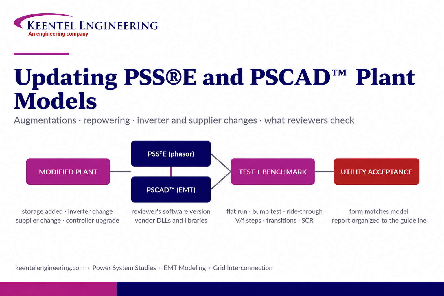
By SANDIP R PATEL
•
September 22, 2026
Learn how PSS®E and PSCAD™ model updates support plant augmentations, repowering, equipment changes, testing, benchmarking, and grid compliance.
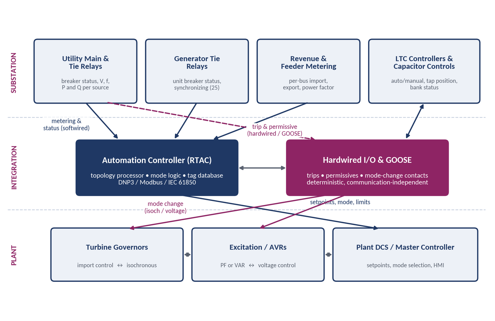
By SANDIP R PATEL
•
September 20, 2026
Learn CHP load following and island detection engineering for campus plants, including protection, controls, power studies, and grid transition design.
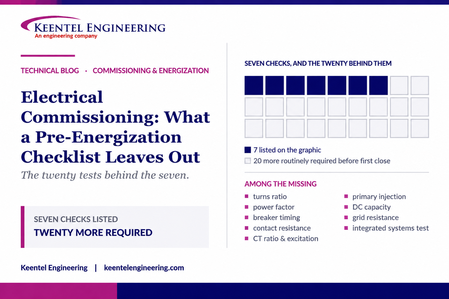
By SANDIP R PATEL
•
September 20, 2026
Learn what a pre-energization checklist misses, including electrical testing, protection checks, commissioning steps, and safe energization practices.





