
A Coordinated Electric System Interconnection Review—the utility’s deep-dive on technical and cost impacts of your project.
Challenge: Frequent false tripping using conventional electromechanical relays
Solution: SEL-487E integration with multi-terminal differential protection and dynamic inrush restraint
Result: 90% reduction in false trips, saving over $250,000 in downtime
| Category | Metric |
|---|---|
| VPP capacity (Lunar Energy) | 650 MW |
| Lunar funding raised | US$232 million |
| Data center BESS example | 31 MW / 62 MWh |
| ERCOT grid-scale batteries | 15+ GW |
| LDES tenders (H1 2026) | Up to 9.3 GW |
| Lithium-ion share of LDES by 2030 | 77% |
| FEOC initial threshold | 55% |
| BESS tariff rate (2026) | ~55% |
| Capacity gain from analytics | 5–15% |
What is T&D Co-Simulation?
Confusing Physical Connections with Logical Nodes in IEC 61850
From the Grid to the Rack: Engineering Continuous Power for the Data Center
Jun 18, 2026 | blog
Why Electrical Design Is the Foundation of Data Center Reliability
Servers and cooling tend to get the attention, but neither matters without one thing delivered continuously and cleanly: electrical power. A data center exists to keep computing available, and availability is fundamentally an electrical promise. A few seconds without power can reboot tens of thousands of servers, corrupt in-flight data, and take services offline across the world. Unlike an office building, a data center cannot tolerate even a momentary interruption.
Meeting that standard takes more than a strong utility feed. It takes a layered electrical system engineered so that no single failure, and no planned maintenance activity, ever reaches the IT load. This guide walks the full path that power takes from the utility connection down to the server, the systems that bridge and back up that power when the grid falters, and the redundancy architecture that ties it all together. It closes on the part Keentel works in most directly: the protection studies and the interconnection engineering that determine whether the facility can be powered safely and brought online at all.
The Keentel lens
Everything inside the fence depends on what happens at the fence. The reliability of a data center's internal power chain is only as good as the capacity secured at the point of interconnection and the protection scheme that lets that capacity be delivered safely. We treat the utility interconnection, the protection and coordination studies, and the internal distribution design as one continuous problem.
The Power Chain: From Utility Service to the Server Rack
Power inside a data center moves through a series of controlled voltage transformations and distribution steps, each one taking electricity a level closer to the sensitive electronics in the racks. Understanding that chain is the foundation for everything that follows.
Utility service and the service entrance
Electricity arrives from the grid at medium voltage, commonly in the range of roughly 13.8 to 34.5 kilovolts for many facilities. As campus loads have grown into the hundreds of megawatts, large hyperscale sites increasingly take service at sub-transmission or transmission voltages instead, which is one of the reasons interconnection has become a gating item for new development. The incoming supply enters through service equipment that meters and terminates the utility connection.
Switchgear: the control center
From the service entrance, power passes into switchgear, which is among the most important pieces of equipment in the building. Switchgear is the control and protection hub: it lets operators isolate circuits, redirect power flows between sources, and protect the system with circuit breakers and protective relays. When a fault occurs, the protective relays and breakers in the switchgear are what clear it quickly and selectively, ideally isolating only the affected section while the rest of the facility keeps running. The quality of that protection scheme is a direct determinant of both safety and uptime.
Step-down transformers
Switchgear feeds step-down transformers that reduce the medium-voltage supply to levels usable inside the building, most commonly 480 volts three-phase for large equipment and primary distribution. Some modern facilities distribute at 400/415 volts to improve efficiency and simplify the path to the rack.
PDUs and rack distribution
Power distribution units (PDUs) take that 480-volt distribution and transform it again to the voltages the IT equipment uses, such as 208 or 120 volts (or 240 volts in a 415-volt scheme). From the PDU, branch circuits feed rack-level power strips, often called rack PDUs, which deliver power directly to the dual power supplies in each server. The net effect is a deliberate cascade, from high-voltage utility supply down through each protected, transformed stage to the electronics themselves.
Conditioning and Bridging Power: The UPS
Distributing power is not enough; it also has to be clean and uninterrupted. Utility power is imperfect, carrying voltage fluctuations, frequency variations, transients, and occasional complete outages, and sensitive electronics react badly to even brief disturbances. The uninterruptible power supply (UPS) sits between the incoming power and the critical load, acting as both a power conditioner and an instantaneous source of backup energy.
How a Double-Conversion UPS Works
A UPS has three core elements: a rectifier, an energy store (typically a battery system), and an inverter. In the dominant data center design, the double-conversion UPS, incoming AC is converted to DC by the rectifier. That DC bus simultaneously charges the batteries and feeds the inverter, which converts it back into clean, tightly regulated AC for the load.
The key insight is that the load is always supplied by the inverter, never directly by the utility. The incoming supply is fully decoupled from the output, so disturbances on the utility side are filtered out before they can reach a server. This is also why the response to an outage is seamless: if utility power fails, the rectifier simply stops receiving input, but the already-charged batteries continue feeding the same inverter. There is no switchover, no transfer time, no flicker. That zero-interruption behavior is exactly what the name describes.
Double conversion vs. line-interactive
Line-interactive UPS designs regulate voltage and switch to battery only when needed, with a brief transfer. They suit small or edge applications. Mission-critical data centers favor double conversion because it delivers the highest power quality and a true zero-transfer response, which is worth the modest efficiency cost. Some units offer an economy mode that bypasses the conversion to save energy, trading away a degree of isolation; whether to enable it is a reliability-versus-efficiency decision.
Battery Technologies
UPS batteries are sized to carry the full load for a short bridge period, typically a few minutes up to around fifteen. That is not meant to ride out a long outage; it is meant to span the seconds it takes for generators to start and stabilize. Two battery technologies dominate, and the choice balances cost, footprint, and service life
| Attribute | Valve-Regulated Lead-Acid (VRLA) | Lithium-Ion |
|---|---|---|
| Upfront cost | Lower | Higher |
| Footprint & weight | Larger and heavier | Compact and lighter |
| Service life | Shorter (often ~3 to 5 years) | Longer (often ~10+ years) |
| Temperature tolerance | More sensitive; needs tight cooling | Tolerates higher temperatures |
| Monitoring | Basic; more manual maintenance | Integrated battery management system |
| Typical fit | Cost-driven or legacy installs | Space-, life-, and performance-driven builds |
The Long Haul: Backup Generators
Batteries bridge seconds and minutes; generators carry the facility through hours and days. Most large data centers use diesel generators, frequently rated at several megawatts each and paralleled to support the full load with redundancy. When utility power fails, these units start automatically and are typically designed to reach rated output and accept load within roughly ten seconds to under a minute, depending on their emergency-power classification.
An automatic transfer switch (ATS) senses the loss of utility power, signals the generators to start, and transfers the building load to generator power once the units are stable. The UPS covers the brief interval between the outage and the moment the generators are carrying the load. On-site fuel storage commonly provides hours to a few days of autonomy, and fuel deliveries extend that further during prolonged grid events. Once generators are online, they assume the load, and the UPS rectifier, now fed by generator power, recharges the batteries while continuing to condition the output.
The Handoff Sequence, Step by Step
When the utility fails, a precisely choreographed sequence plays out automatically, with no human intervention required:
- Utility power is lost.
- The UPS instantly carries the load from its batteries through the same inverter, with no transfer time.
- The transfer scheme detects the outage and signals the generators to start.
- The generators start, reach stable voltage and frequency, and accept load, typically within about ten seconds to under a minute.
- The transfer switch moves the building load onto generator power.
- The UPS, now fed by the generators, recharges its batteries while continuing to condition power to the servers.
- When utility power returns and stabilizes, the system transfers back and the generators shut down after a cooldown.
The result is a power source that, from the perspective of the servers, never went away.
Designing Against Failure: Redundancy Architecture
Redundancy is the design principle that ties the whole system together. Rather than depending on any single component, the electrical system installs spare capacity and duplicate paths so that a failure, or a planned maintenance outage, can be absorbed without affecting the load. The same vocabulary describes redundancy across both electrical and cooling systems.
| Level | Definition | What it tolerates |
|---|---|---|
| N | Exactly the capacity required to serve the load, no spare | Nothing; any failure or service event reduces capacity |
| N+1 | One spare unit beyond the requirement | A single component failure or one unit out for maintenance |
| N+2 | Two spare units beyond the requirement | A failure even while another unit is already offline |
| 2N | Two fully independent systems, each able to carry 100% of the load | Loss of an entire system or distribution path |
| 2N+1 | Fully duplicated systems plus an additional spare | A failure within a path even while its twin is being serviced |
N+1 is the most common level in enterprise facilities because it offers a strong balance of reliability and cost: a UPS plant that needs four modules is built with five, so any one module can fail or be serviced while the load stays fully supported. 2N goes further by duplicating the entire infrastructure, two utility feeds, two switchgear lineups, two UPS systems, and two distribution paths, each sized for the
full load. Beyond these, distributed-redundancy schemes (for example, arranging three systems so that any two can carry the load) can achieve fault tolerance with less than full duplication, trading some design complexity for capital efficiency.
A/B Distribution, Dual-Corded Loads, and Transfer Switches
In a 2N design, the duplication extends all the way to the rack. Two independent power paths, conventionally called the A side and the B side, run from separate sources through separate UPS systems and PDUs to the racks. Servers with dual power supplies are corded to both paths, so the loss of either side, whether from a fault or planned maintenance, leaves the equipment running on the other without interruption.
For equipment that has only a single power input, a static transfer switch (STS) provides a similar benefit by switching that load between the A and B sources in milliseconds. Together, dual-corded distribution and static transfer switches are what let an entire
power path be taken out of service for maintenance while the IT load continues uninterrupted, the practical expression of concurrent maintainability.
Tiers, Concurrent Maintainability, and Five-Nines
Redundancy levels map closely onto the data center tier classifications used to describe overall reliability. Higher tiers carry more redundancy and, importantly, more independence between paths.
| Tier | Defining characteristic | Typical redundancy |
|---|---|---|
| Tier I | Basic capacity; a single, non-redundant distribution path | N |
| Tier II | Redundant capacity components on a single distribution path | N+1 components |
| Tier III | Concurrently maintainable: any component or path can be serviced without downtime | N+1 with multiple distribution paths (one active) |
| Tier IV | Fault tolerant: sustains a single worst-case failure with no impact; compartmentalized, continuously cooled | 2N or 2N+1, multiple active paths |
Two distinctions matter most. Concurrent maintainability (the threshold for Tier III) means any single component or distribution path can be removed from service for maintenance or replacement without affecting the IT load; it requires both redundant components and independent distribution paths. Fault tolerance (Tier IV) is stronger still: the facility can absorb an unplanned failure of any single component or path with no impact, which generally implies a 2N architecture with multiple simultaneously active paths and physical separation between them.
These design choices are what allow well-run facilities to target availability of 99.999 percent or higher, the so-called five-nines level, which corresponds to only about five minutes of downtime per year. Reliability at that level is not achieved by any single device; it is the product of layered distribution, instantaneous backup, and disciplined redundancy working together.
The Studies Behind a Safe, Reliable Power System
Redundant equipment only delivers reliability if the system that connects it is engineered correctly, and that is established through power system studies rather than assumed. Several are central to a sound data center electrical design:
- Load flow analysis confirms that voltages and equipment loadings stay within limits across normal and contingency configurations, including when the load runs on generators.
- Short-circuit analysis establishes the fault currents the system must withstand, so breakers and switchgear are rated to interrupt them safely.
- Protective device coordination tunes relays and breakers so that the device closest to a fault clears it first, isolating the smallest possible section and preserving uptime everywhere else.
- Arc-flash analysis quantifies the incident energy at each location, driving labeling and personal protective equipment requirements that keep maintenance work safe, which is a prerequisite for true concurrent maintainability.
Done well, these studies are what make the difference between a system that is redundant on paper and one that actually rides through faults and maintenance without dropping the load.
Before the Load Arrives: The Interconnection Dimension
There is a layer upstream of everything described so far. All of this internal infrastructure assumes the facility can secure the grid capacity it needs in the first place, and at the scale of modern data centers that assumption is no longer safe to make. Loads now routinely reach into the hundreds of megawatts, which pushes service from distribution voltages up toward sub-transmission and transmission, and brings the project squarely into the utility interconnection process: queue positions, system impact and facilities studies, point-of-interconnection engineering, and the protection and modeling requirements that come with connecting a large load to the bulk power system.
These realities increasingly determine site viability and schedule more than any decision made inside the building. The most carefully engineered internal power chain is of no value if capacity cannot be delivered to the site on a workable timeline. That is why we treat interconnection not as a downstream utility formality but as a first-order design input, evaluated before the rest of the electrical design is locked in.
How Keentel Engineering Approaches Data Center Power
Keentel Engineering is a power systems and interconnection consulting firm, and data center electrical design sits at the center of what we do. We connect the internal critical-power architecture to the grid-side realities that govern whether and when a facility can be energized: point-of-interconnection engineering across medium, high, and extra-high voltage; system studies including load flow, short-circuit, protective device coordination, and arc-flash analysis; substation and switchgear design; owner's engineer services; and NERC operations and planning compliance for facilities that interact with the bulk power system.
If you are siting a new data center, sizing and securing a large load, or coordinating the electrical design for a new or expanding campus, we can help align the internal reliability strategy, the protection scheme that makes it safe, and the interconnection path that ultimately determines your route to energization.
Frequently Asked Questions
A quick-reference set of answers to the questions that come up most often in data center electrical design.
What is the path power takes through a data center?
Electricity arrives from the utility at medium voltage, passes through service equipment into switchgear, then through step-down transformers to building distribution voltage (commonly 480 volts). Power distribution units step it down again to server voltages such as 208 or 120 volts, and branch circuits and rack power strips deliver it to the dual power supplies in each server. Along the way the power also passes through the UPS, which conditions and backs it up.
What does switchgear do?
Switchgear is the control and protection hub for incoming power. It lets operators isolate circuits, redirect power between sources, and protect the system with circuit breakers and protective relays. When a fault occurs, the switchgear is what clears it quickly and, ideally, selectively, so only the affected section is isolated while the rest of the facility keeps running.
What is a UPS and why is it necessary?
An uninterruptible power supply sits between the incoming power and the servers. It conditions the electricity, filtering out utility disturbances, and provides instantaneous battery backup if the utility fails. It is necessary because data centers cannot tolerate even a momentary interruption, which could reboot thousands of servers and disrupt services worldwide.
How does a double-conversion UPS work?
It converts incoming AC to DC with a rectifier, uses that DC to both charge the batteries and feed an inverter, and the inverter converts it back to clean, regulated AC for the load. Because the load is always supplied by the inverter rather than directly by the utility, the input is fully decoupled from the output and utility disturbances never reach the servers.
Why is the transition to battery power seamless?
In a double-conversion UPS the inverter already feeds the load continuously from the DC bus. When utility power fails, the rectifier simply stops receiving input while the charged batteries keep feeding that same inverter. Nothing switches over, so there is no transfer time, flicker, or interruption.
How long can UPS batteries power a data center?
Only a short bridge period, typically a few minutes up to around fifteen. That is by design. The batteries are meant to span the seconds it takes for backup generators to start and stabilize, not to ride out a long outage on their own.
What is the difference between double-conversion and line-interactive UPS?
Double conversion continuously rebuilds the AC waveform and offers the highest power quality with a true zero-transfer response, which is why mission-critical data centers prefer it. Line-interactive units regulate voltage and switch to battery only when needed, with a brief transfer; they are better suited to small or edge applications.
VRLA or lithium-ion batteries, which is better?
It depends on the priorities. VRLA (valve-regulated lead-acid) is cheaper upfront but larger, heavier, shorter-lived, and more temperature-sensitive. Lithium-ion costs more initially but is compact, longer-lived, tolerates higher temperatures, and includes integrated monitoring. Space-, life-, and performance-driven builds increasingly favor lithium-ion.
What role do backup generators play?
Generators carry the facility through extended outages, after the UPS bridges the first seconds. Most large data centers use diesel generators rated at several megawatts, which start automatically on a utility failure and typically reach full output within about ten seconds to under a minute, then power the site for as long as fuel is available.
How long can a data center run on generator power?
On-site fuel storage commonly provides hours to a few days of autonomy, and arranged fuel deliveries can extend operation through prolonged grid events. The exact duration depends on tank capacity, load, and the fueling plan.
What is an automatic transfer switch (ATS)?
An ATS senses the loss of utility power, signals the generators to start, and transfers the building load onto generator power once the units are stable. It also transfers back when the utility returns. The UPS covers the brief interval before the generators are carrying the load.
What does N mean in redundancy?
N is the amount of equipment required to serve the full load with no spare. If a facility needs four UPS modules, then four modules equal N. An N configuration has no redundancy: any failure or maintenance event reduces capacity, which is why most modern facilities avoid it.
What is N+1 redundancy?
N+1 adds one spare unit beyond what is required. If four UPS modules are needed, five are installed; four carry the load and the fifth provides backup. Any single unit can fail or be taken offline for maintenance without affecting the load. It offers a strong balance of reliability and cost, which is why it is the most common level.
What is 2N redundancy?
2N duplicates the entire infrastructure: two independent systems, each capable of carrying the full load by itself. That typically means two utility feeds, two switchgear lineups, two UPS systems, and two distribution paths. The loss of an entire path leaves the load fully supported by its twin.
What are A and B power paths, and dual-corded servers?
In a 2N design, two independent paths (the A side and the B side) run from separate sources to the racks. Servers with dual power supplies are connected to both, so losing either side leaves the equipment running on the other. For single-input equipment, a static transfer switch can switch the load between A and B in milliseconds.
What is concurrent maintainability?
It means any single component or distribution path can be taken out of service for maintenance or replacement without affecting the IT load. It requires both redundant components and independent distribution paths, and it is the defining characteristic of a Tier III facility.
What is the difference between Tier III and Tier IV?
Tier III is concurrently maintainable: any component or path can be serviced without downtime, generally using N+1 with multiple paths where one is active. Tier IV is fault tolerant: it can absorb an unplanned single failure with no impact, which generally requires a 2N or 2N+1 architecture with multiple simultaneously active, physically separated paths.
What does five-nines reliability mean?
Five-nines refers to 99.999 percent availability, which corresponds to roughly five minutes of downtime per year. It is achieved not by any single device but by combining layered distribution, instantaneous backup, and disciplined redundancy across the whole system.
What power system studies does a data center need?
Core studies include load flow (verifying voltages and loadings across configurations), short-circuit (establishing fault duties so equipment is correctly rated), protective device coordination (ensuring the nearest device clears a fault first), and arc-flash analysis (quantifying incident energy for safe maintenance). These are what turn redundant equipment into genuine reliability.
Why does interconnection matter so much for new data centers?
Modern data center loads reach into the hundreds of megawatts, which pushes service toward sub-transmission and transmission voltages and into the utility interconnection process, including queue positions, system studies, and point-of-interconnection engineering. Securing capacity on a workable timeline increasingly determines site viability and schedule more than any internal design decision, so it should be evaluated first.

About the Author:
Sonny Patel P.E. EC
IEEE Senior Member
In 1995, Sandip (Sonny) R. Patel earned his Electrical Engineering degree from the University of Illinois, specializing in Electrical Engineering . But degrees don’t build legacies—action does. For three decades, he’s been shaping the future of engineering, not just as a licensed Professional Engineer across multiple states (Florida, California, New York, West Virginia, and Minnesota), but as a doer. A builder. A leader. Not just an engineer. A Licensed Electrical Contractor in Florida with an Unlimited EC license. Not just an executive. The founder and CEO of KEENTEL LLC—where expertise meets execution. Three decades. Multiple states. Endless impact.
Services

Let's Discuss Your Project
Let's book a call to discuss your electrical engineering project that we can help you with.
About the Author:
Sonny Patel P.E. EC
IEEE Senior Member
In 1995, Sandip (Sonny) R. Patel earned his Electrical Engineering degree from the University of Illinois, specializing in Electrical Engineering . But degrees don’t build legacies—action does. For three decades, he’s been shaping the future of engineering, not just as a licensed Professional Engineer across multiple states (Florida, California, New York, West Virginia, and Minnesota), but as a doer. A builder. A leader. Not just an engineer. A Licensed Electrical Contractor in Florida with an Unlimited EC license. Not just an executive. The founder and CEO of KEENTEL LLC—where expertise meets execution. Three decades. Multiple states. Endless impact.
Leave a Comment
Thank you for contacting us.
We will get back to you as soon as possible.
We will get back to you as soon as possible.
Oops, there was an error sending your message.
Please try again later.
Please try again later.
Related Posts
By SANDIP R PATEL
•
July 31, 2026
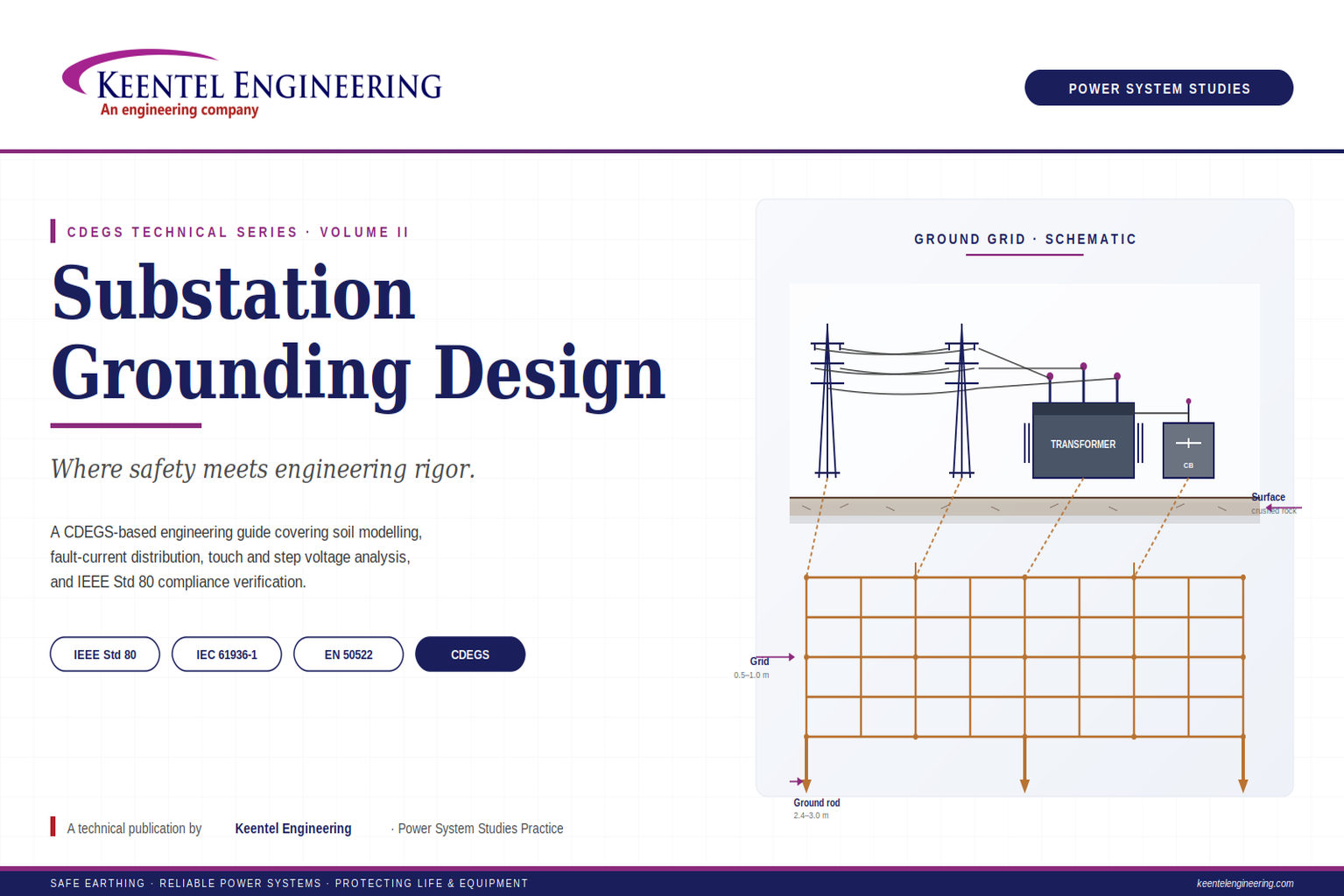
Learn substation grounding design using IEEE Std 80, CDEGS, soil resistivity modeling, touch and step voltage analysis, GPR, and earthing best practices.
By SANDIP R PATEL
•
July 29, 2026
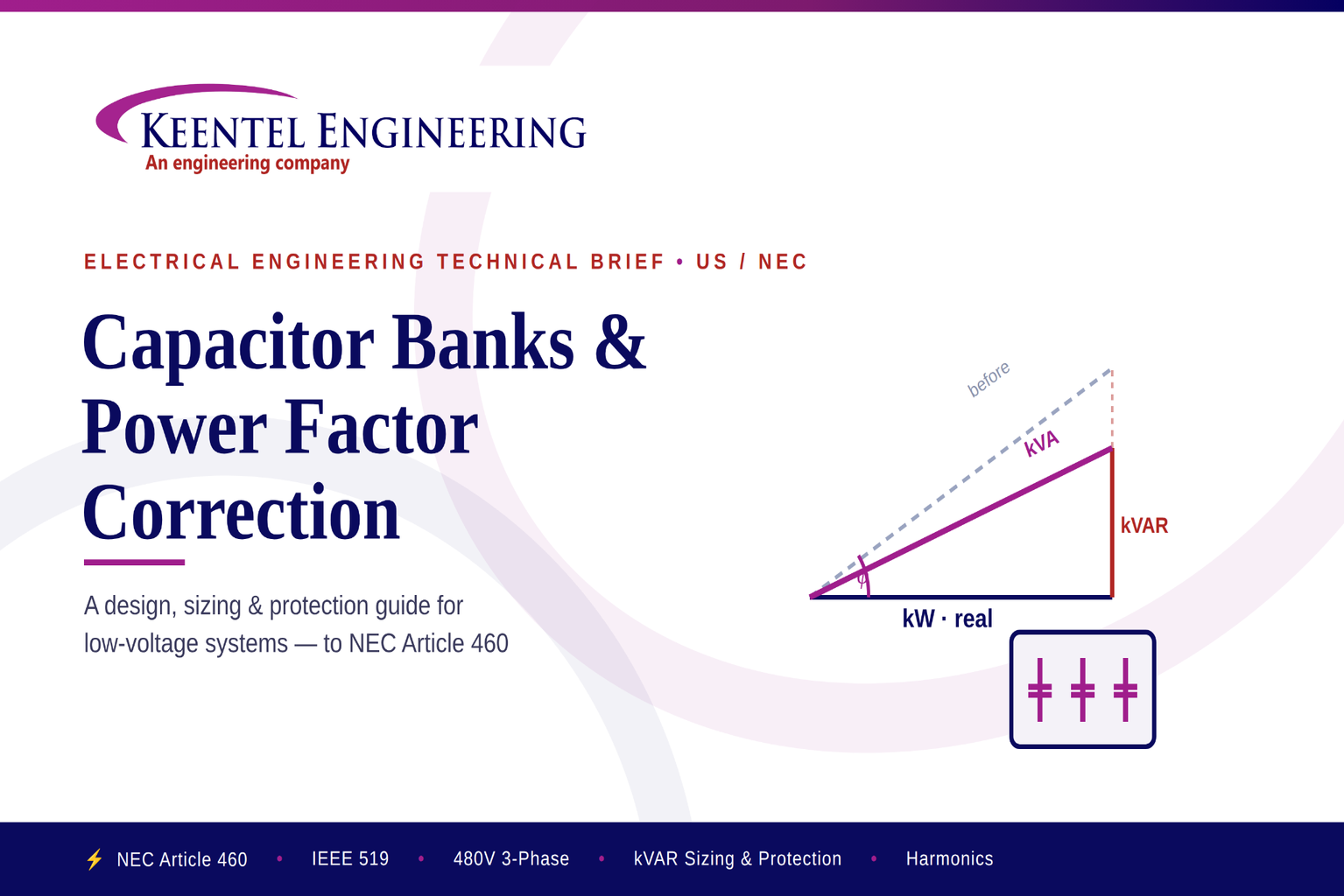
Learn capacitor bank sizing, power factor correction, NEC Article 460 requirements, harmonic mitigation, protection, and installation for industrial power systems.
By SANDIP R PATEL
•
July 29, 2026
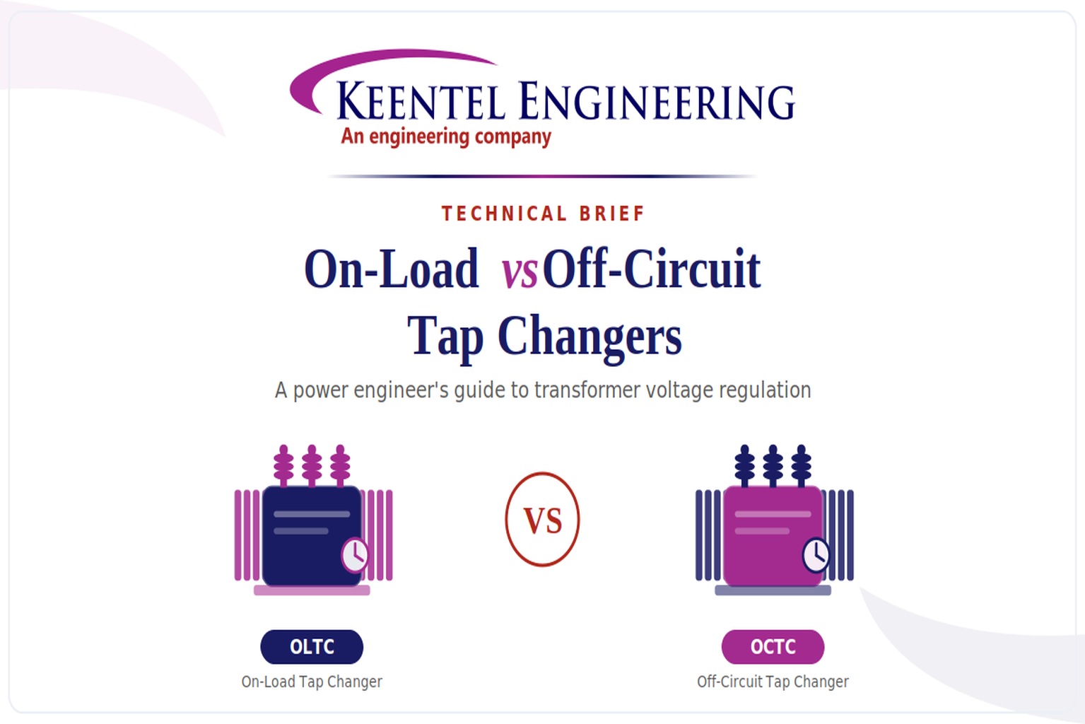
Learn the differences between On-Load and Off-Circuit Tap Changers, including OLTC vs OCTC operation, voltage regulation, IEEE standards, maintenance, and transformer selection.
By SANDIP R PATEL
•
July 28, 2026
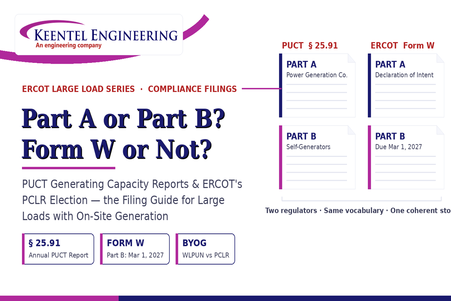
Learn the differences between the PUCT Generating Capacity Report and ERCOT Form W, including Part A vs Part B, PCLR, WLPUN, BYOG projects, and Batch Zero compliance.
By SANDIP R PATEL
•
July 28, 2026
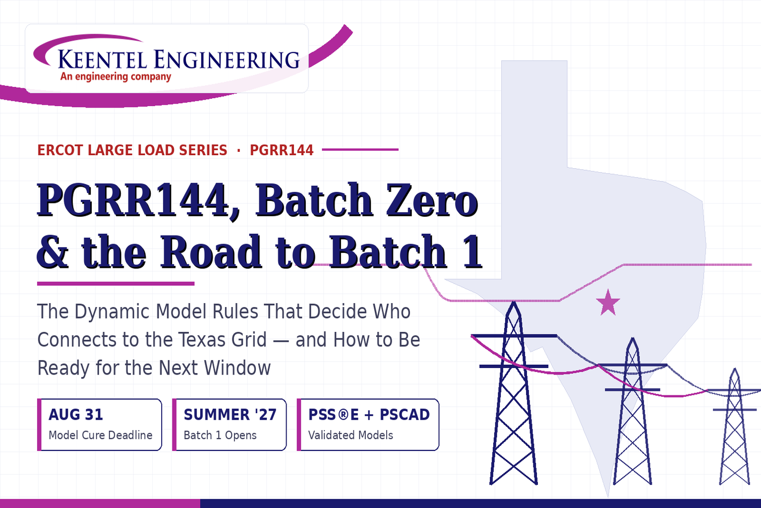
Learn how PGRR144, Batch Zero, and Batch 1 affect ERCOT large-load interconnections, dynamic model requirements, MQT testing, PERC1, and project readiness.
By SANDIP R PATEL
•
July 28, 2026
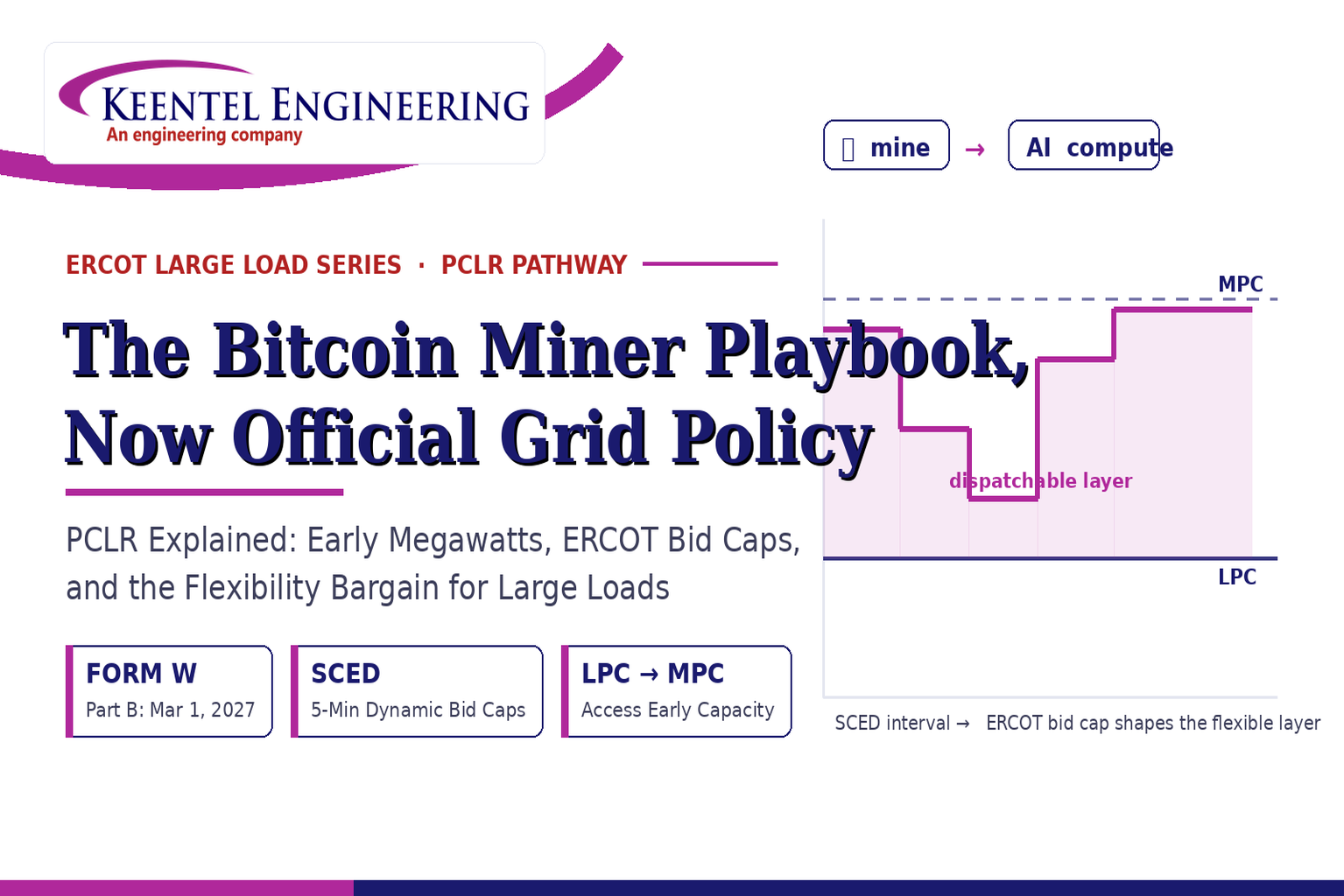
ERCOT PCLR Batch Zero large-load interconnection pathway
By SANDIP R PATEL
•
July 27, 2026
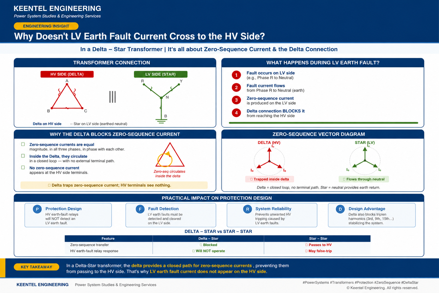
Learn why LV earth-fault current cannot cross a Delta-Star transformer, how zero-sequence current behaves, and what it means for protection design.

By SANDIP R PATEL
•
July 27, 2026
Learn how gas-insulated substations (GIS) improve safety, reliability, and space efficiency with 138 kV design, protection, insulation coordination, and real-world case studies.
By SANDIP R PATEL
•
July 25, 2026
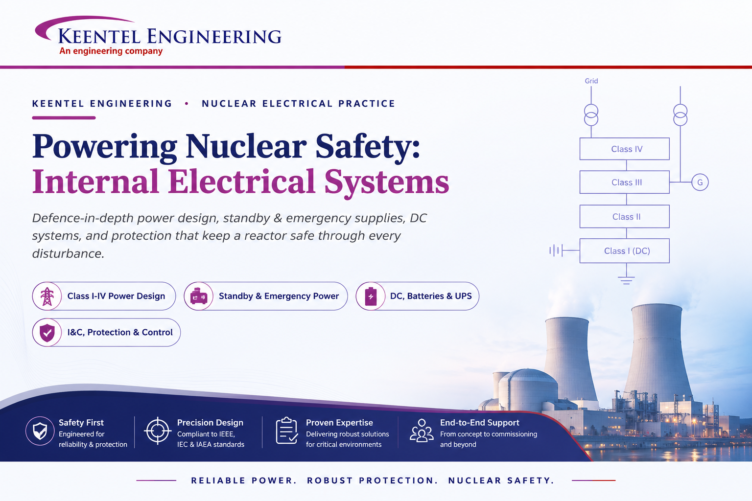
Learn how Class I–IV electrical systems, defence-in-depth, standby and emergency power, DC systems, protection, and load transfer ensure nuclear power plant safety.