A Coordinated Electric System Interconnection Review—the utility’s deep-dive on technical and cost impacts of your project.
Challenge: Frequent false tripping using conventional electromechanical relays
Solution: SEL-487E integration with multi-terminal differential protection and dynamic inrush restraint
Result: 90% reduction in false trips, saving over $250,000 in downtime
| Category | Metric |
|---|---|
| VPP capacity (Lunar Energy) | 650 MW |
| Lunar funding raised | US$232 million |
| Data center BESS example | 31 MW / 62 MWh |
| ERCOT grid-scale batteries | 15+ GW |
| LDES tenders (H1 2026) | Up to 9.3 GW |
| Lithium-ion share of LDES by 2030 | 77% |
| FEOC initial threshold | 55% |
| BESS tariff rate (2026) | ~55% |
| Capacity gain from analytics | 5–15% |
What is T&D Co-Simulation?
Confusing Physical Connections with Logical Nodes in IEC 61850
How Data Centers Actually Work: The Electrical and Mechanical Systems Behind Continuous Uptime
Jun 18, 2026 | blog
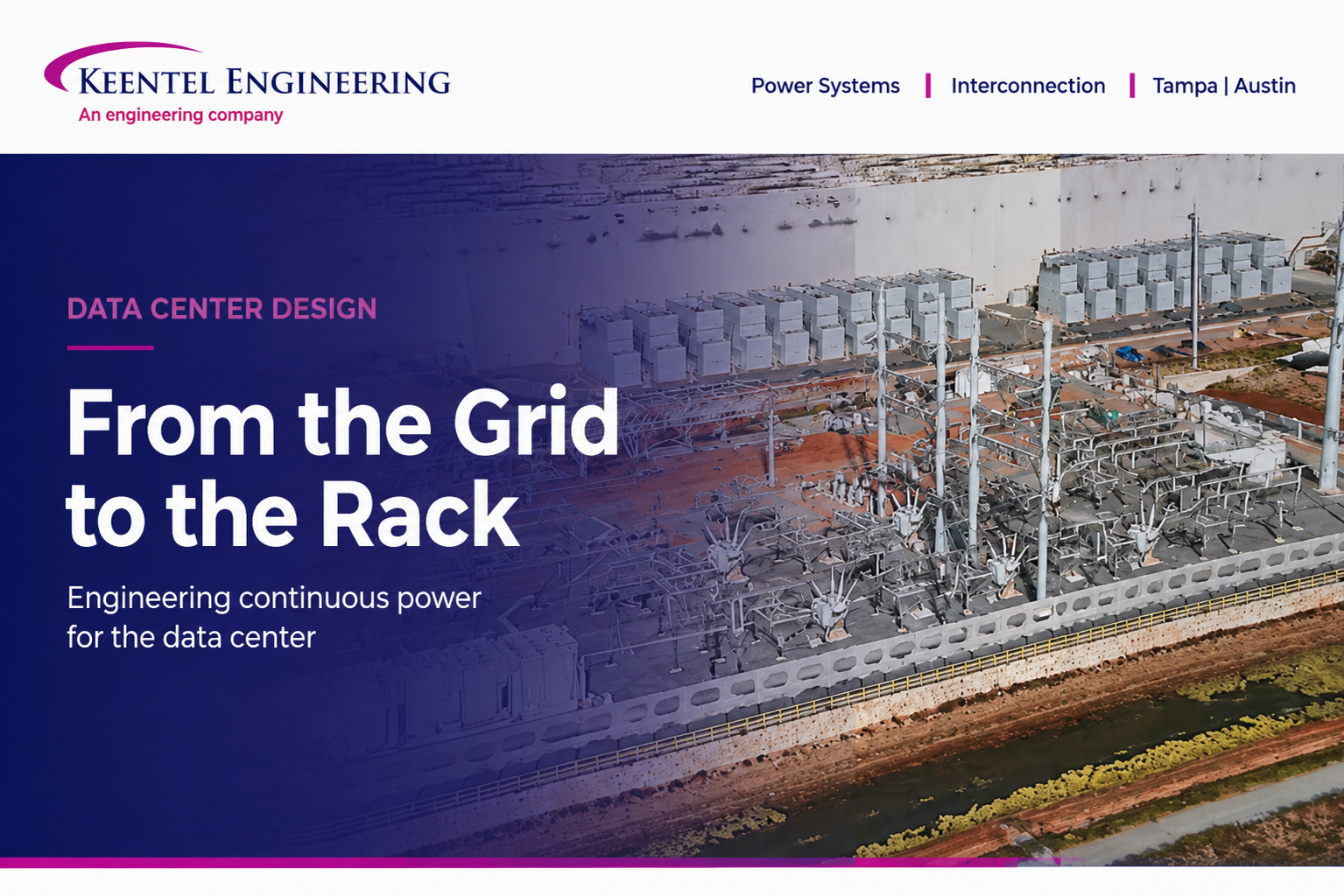
The Data Center as an Energy-Conversion Building
Every email, stream, transaction, and AI query lives somewhere physical: a building filled with servers, electrical infrastructure, and cooling equipment running without pause. From the outside a data center looks like a windowless warehouse. Inside, it is something more specific than an IT facility. It is an energy-conversion building. Electricity goes in, computing work is performed, and heat comes out, and essentially every watt delivered to a server reappears as heat that must be removed. The entire facility exists to manage that conversion safely and continuously.
That framing is the key to understanding how these buildings are designed. The two largest engineered systems, power and cooling, are not independent: they are the input and output sides of the same energy flow, and they are sized against each other. This article follows that flow end to end, from the utility connection down to the server and back out as heat, and then looks at the controls and the redundancy that make the whole thing dependable.
Why this matters for power planning
Because nearly all delivered power becomes heat, the cooling system is itself one of the largest electrical loads in the building. Power in and heat out are two views of the same number, which is why the total facility load presented to the grid, and the interconnection that must support it, can only be understood by looking at power and cooling together.
The Three System Groups
Although the infrastructure looks complex, most of it falls into three groups that work as one.
Electrical systems bring power into the building and distribute it safely to the servers, spanning the utility connection, switchgear, transformers, backup power, and distribution equipment. The objective is simple: power must always be available.
Mechanical cooling systems remove the heat the servers produce, using some combination of chillers, cooling towers, pumps, air handlers, and increasingly liquid-cooling equipment located right at the racks. The objective is to keep equipment within safe temperatures at all times.
Controls and monitoring tie the electrical and mechanical systems into a single operating environment, tracking temperatures, power, equipment status, and alarms, and responding automatically to changing conditions or failures. In a modern facility this layer is as important as the physical equipment.
Following the Power: From the Grid to the Server Rack
Power inside a data center moves through a sequence of controlled transformations and protected distribution stages, each taking electricity a step closer to the electronics. The chain begins well outside the building.
Utilities transmit power at high voltage and correspondingly low current, because line losses rise with the square of current; moving energy at high voltage is what makes long-distance delivery efficient. That power steps down at substations and is routed to the campus. From there, the on-site chain takes over:
Three Problems Every Data Center Must Solve
Regardless of size, every data center is built to solve three problems at once, and each one drives major design decisions.
Continuous power
Servers cannot simply ride out a power loss. Even a brief interruption can corrupt in-flight data or take services offline for thousands or millions of users. Power must remain available even when utility power is interrupted or individual equipment fails, which is why the electrical system is layered with conditioning and multiple backup sources rather than relying on the grid alone.
Continuous cooling
Because servers generate heat constantly, cooling has to run constantly. If it stops, temperatures climb in minutes, forcing equipment to throttle or shut down to protect itself. Cooling here is not about human comfort; it is about equipment survival, and it carries the same intolerance for interruption as the power system.
Continuous operation
The facility must keep running through maintenance, failures, and repairs. That requirement, more than any other, is what drives the pervasive use of redundancy and multiple paths across both electrical and mechanical systems, so that work can be done and components can fail without taking the IT load down.
| Stage | What it does | Typical voltage |
|---|---|---|
| Utility / transmission | Power is generated and transmitted at high voltage to minimize line losses | Transmission (well above 35 kV) |
| Substation | Steps voltage down and routes power toward the campus | High to medium voltage |
| Service entrance switchgear | First on-site equipment: overcurrent protection, isolation, metering, protective relays | Medium voltage (~12 to 34.5 kV) |
| Step-down transformer | Converts medium voltage to building distribution voltage | MV down to 480 V |
| Generators + paralleling / transfer gear | Detect utility loss, start, synchronize, and assume full load (N+1) | 480 V |
| UPS (N+1 modules) | Conditions power and provides an instantaneous battery bridge during transfer | 480 V |
| Output switchboard / distribution switchgear | Breaker protection, branch segmentation, maintenance isolation | 480 V |
| PDU (power distribution unit) | Steps voltage down again; branch protection and load monitoring | 480 to 208 / 415 V |
| RPP (remote power panel) | Extends branch circuits into the white space; supports scalability | 208 / 415 V |
| Rack PDU (rPDU) | Distributes to individual servers; per-outlet monitoring and switching | 208 / 120 / 240 V |
| Servers | Convert electrical energy into computation; nearly every watt becomes heat | Low-voltage DC internally |
Two stages deserve emphasis. The
service entrance switchgear is where the facility takes control of its own power: it provides protection, isolation, metering, and the protective relaying that clears faults quickly and selectively. And the backup chain, generators plus an automatic transfer switch or generator paralleling switchgear, is what carries the building through a utility outage. Because generators need several seconds to start and stabilize while servers cannot tolerate even milliseconds of interruption, the UPS bridges that gap: it conditions incoming power continuously and supplies instantaneous battery power the moment the utility fails, then recharges once the generators are carrying the load. Modern UPS plants increasingly use lithium-ion batteries over legacy valve-regulated lead-acid for their higher energy density, smaller footprint, longer life, and lower maintenance, and they are typically arranged in N+1 modules with static and maintenance bypass so they can be serviced without dropping the load.
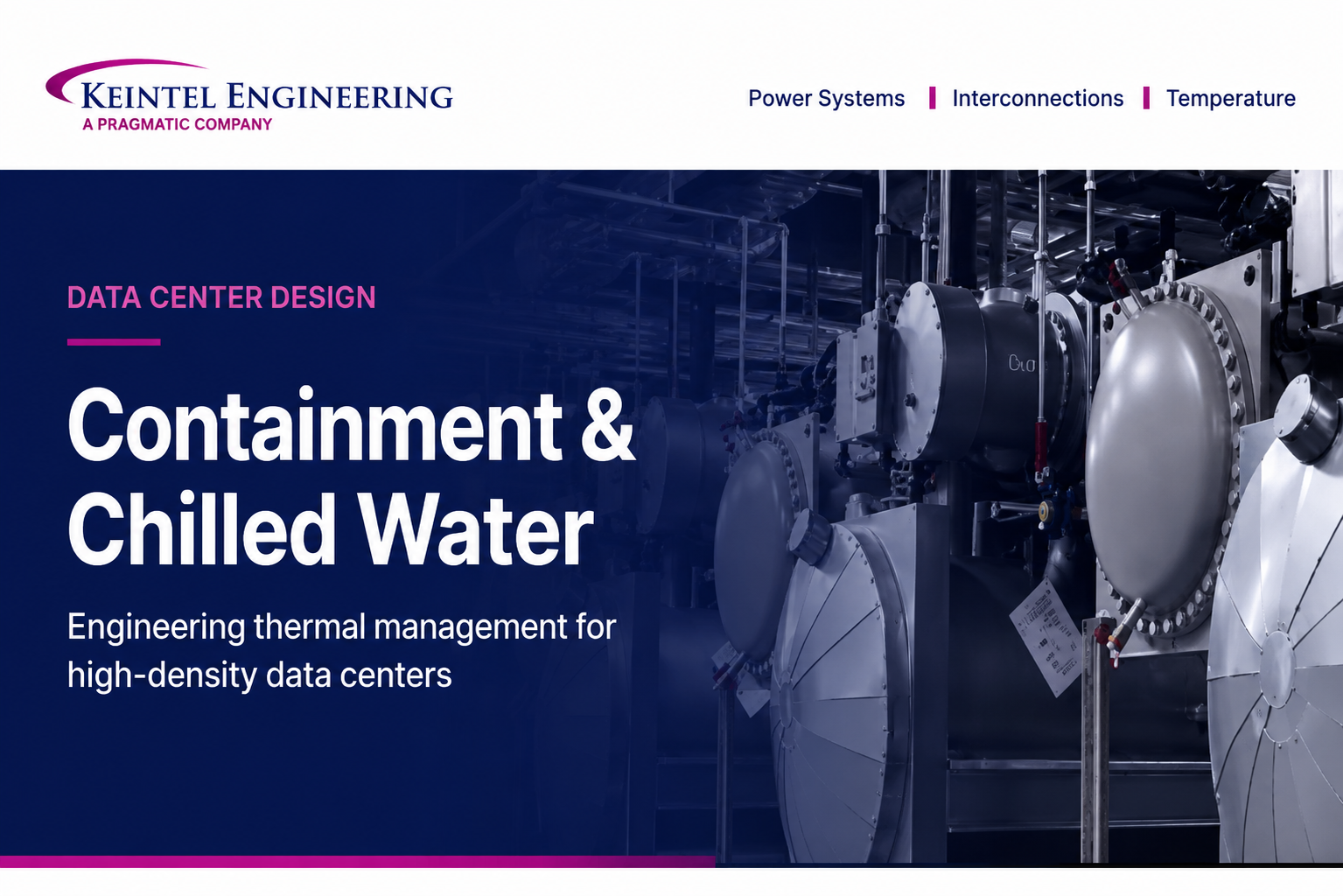
Following the Heat: The Cooling Spectrum
Once power reaches the servers, electrical engineering hands off to mechanical engineering. Every kilowatt delivered becomes thermal energy that has to be removed instantly and continuously. How that is done depends overwhelmingly on one variable: heat density, the power dissipated per rack.
That number has climbed dramatically. Traditional enterprise racks once averaged roughly 3 to 5 kilowatts; many today run 10 to 20; and AI and GPU clusters can exceed 50, 80, or even 100 kilowatts per rack. Air has a relatively low heat capacity, so as density rises, air-based systems must move ever larger volumes faster, consuming more fan energy until they reach physical limits. This is why cooling has steadily shifted from cooling whole rooms to capturing heat at its source, producing four broad methods arranged along a density spectrum.
| Method | How it works | Typical density | Best fit |
|---|---|---|---|
| Room-based air | CRAC units (direct-expansion) or CRAH units (chilled water) push cold air, often via a raised-floor plenum and perforated tiles, organized into hot and cold aisles with containment | Up to ~10-15 kW/rack | Lower to moderate density; simple and familiar |
| Close-coupled air | In-row units between racks and rear-door heat exchangers cool at the row or rack, shortening airflow paths and reducing mixing | ~15-40 kW/rack | Moderate to higher density; independent row cooling |
| Direct-to-chip liquid | Cold plates mounted on CPUs and GPUs carry heat away in a coolant loop to a CDU that separates the facility water loop from the server loop | ~50-100+ kW/rack | High-density and AI; the dominant emerging approach |
| Immersion | Entire servers are submerged in a dielectric fluid; single-phase pumps it to a heat exchanger, two-phase removes heat by boiling and condensing | Very high | Extreme density; specialized, still niche |
The progression is not a replacement so much as a layering. Room-based air remains viable for lower densities and is familiar to most mechanical contractors. Close-coupled air extends air's useful range and lets different rows be cooled independently when load profiles vary. Direct-to-chip liquid, now becoming standard for AI workloads, exploits liquid's far greater heat-transfer capacity to handle densities air cannot, and because its loop can run warmer than traditional chilled water, it often enables economized heat rejection for much of the year, cutting or eliminating compressor energy. Immersion pushes further still, eliminating high-volume airflow entirely at the cost of specialized hardware. Most high-density facilities now run a mix, with the choice at each location driven by density, climate, water availability, energy cost, redundancy requirements, and the balance between capital cost and operating efficiency. There is no single universal answer.
The density inflection
Rising rack density is the single force reshaping data center design today. It is pulling liquid cooling into the mainstream, changing how facility water systems are planned, and pushing total campus loads, and therefore
interconnection requirements, sharply upward. Power and cooling decisions that used to be made separately now have to be made together, against the same density assumptions.
Controls and Monitoring: The Facility's Nervous System
The third system group is easy to overlook because it is mostly invisible, but it is what turns a collection of equipment into a coordinated, self-protecting facility. Building management and automation systems supervise the mechanical plant; electrical power monitoring systems watch the power chain; and data center infrastructure management software ties the whole picture together. These systems continuously track temperatures, power draw, equipment status, and alarms, and they act on what they see, staging cooling capacity up and down, initiating failover when a component drops out, and alerting operators before a developing problem becomes an outage.
In a facility whose defining requirement is continuous operation, this automated awareness is not a convenience; it is a core reliability system. The handoffs that keep the load alive during a utility failure, UPS to generator, primary cooling to backup, happen on timescales too short for human reaction, so the controls layer has to be engineered with the same rigor as the equipment it governs.
Redundancy and Uptime: Why Nothing Is Single-Threaded
The drive for continuous operation expresses itself, everywhere, as redundancy: spare capacity and duplicate paths so that a failure or a maintenance event is absorbed without reaching the load. The same vocabulary applies to both power and cooling.
| Level | Meaning |
|---|---|
| N | Exactly the capacity required to serve the load, with no spare |
| N+1 | One spare unit beyond the requirement; the most common level, balancing reliability and cost |
| 2N | Two fully independent systems, each able to carry the entire load by itself |
These levels map onto the industry tier classifications used to describe reliability. Lower tiers have little or no redundancy; mid tiers add redundant components; higher tiers add independent distribution paths so the facility is concurrently maintainable (any component or path can be serviced without downtime) and ultimately fault tolerant (it can absorb an unplanned single failure with no impact, generally a 2N architecture). Layered correctly across generators, UPS plant, distribution paths, chillers, pumps, towers, and in-room cooling, this is what lets well-run facilities target availability around 99.999 percent, roughly five minutes of downtime a year. The detailed mechanics of the power chain and of the cooling plant are explored further in our companion articles on data center electrical systems and on containment and chilled water.
Why Data Centers Don't Behave Like Other Buildings
From the curb, a data center can resemble any commercial building, but operationally it is a different animal. An office building's load rises and falls with occupancy, cooling demand cycles through the day, and equipment switches on and off. A data center's electrical load is essentially constant, its cooling demand is continuous, and its systems rarely shut down. Failure tolerance differs just as sharply: a cooling failure in an office is a comfort problem, while a power or cooling failure in a data center is an immediate operational risk. That is why these facilities are built with redundant equipment, multiple power and cooling paths, and designs that allow maintenance without shutting down, characteristics that would be unusual, and unnecessary, in almost any other building type.
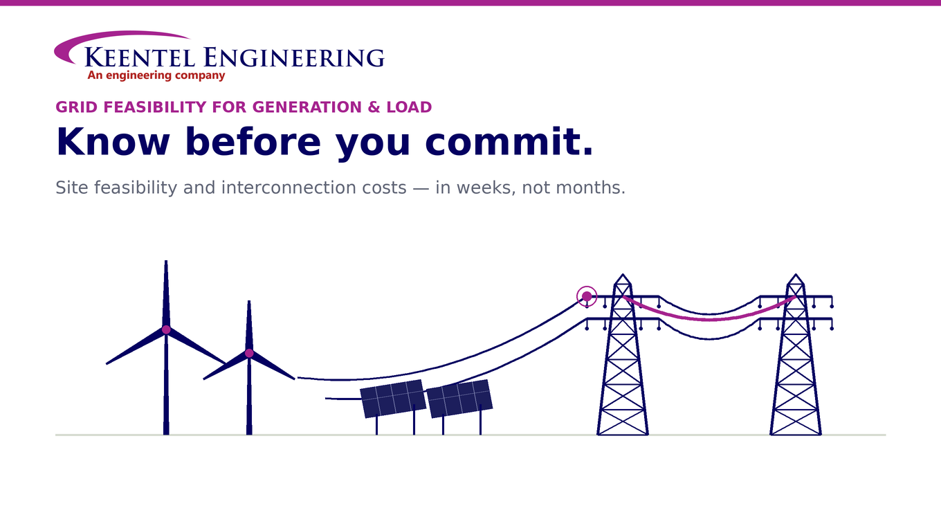
Before the Load Arrives: The Interconnection Dimension
There is one more layer, upstream of everything above. All of this internal infrastructure presumes the facility can secure the grid capacity it needs, and at modern scale that is no longer a safe presumption. As campus loads climb into the hundreds of megawatts, driven in large part by the density trends reshaping cooling, service moves from distribution voltages toward sub-transmission and transmission, and the project enters the utility interconnection process: queue positions, system impact and facilities studies, point-of-interconnection engineering, and the protection and modeling obligations of connecting a large load to the bulk power system.
Increasingly, these realities govern site viability and schedule more than any decision made inside the building. The most elegantly engineered power chain and cooling plant are worth nothing if capacity cannot be delivered to the site on a workable timeline. That is why interconnection belongs at the front of the design conversation, not the end of it.
How Keentel Engineering Approaches Data Center Design
Keentel Engineering is a power systems and interconnection consulting firm, and we treat a data center as the integrated energy-conversion building it is, connecting the internal power and cooling architecture to the grid-side realities that determine whether and when it can be energized. Our work spans point-of-interconnection engineering across medium, high, and extra-high voltage; power system studies including load flow, short-circuit, protective device coordination, and arc-flash analysis; substation and switchgear design; owner's engineer services; and NERC operations and planning compliance for facilities that interact with the bulk power system.
Whether you are evaluating a site, sizing and securing a large load, or coordinating the electrical and mechanical design for a new or expanding campus, we can help align the internal reliability strategy with the interconnection path that ultimately defines your route to bringing the facility online
Frequently Asked Questions
A quick-reference set of answers to the questions that come up most often about how data centers work.
What does a data center actually do?
At its simplest, a data center processes and distributes digital information using rows of servers that run continuously. From an engineering standpoint it is best understood as an energy-conversion building: electricity goes in, computing work is performed, and essentially all of that energy comes back out as heat that must be removed.
Why do data centers use so much energy?
Servers run 24 hours a day, every day, at a nearly constant load, and they are packed densely. On top of the computing load, the cooling system needed to remove the resulting heat is itself a major consumer. Unlike an office building, there is no nightly or seasonal lull, so the energy draw is continuous and large.
What are the three problems every data center must solve?
Continuous power (servers cannot tolerate even brief interruptions), continuous cooling (heat is generated constantly and must be removed to keep equipment alive), and continuous operation (maintenance and failures must happen without taking the facility down). The third requirement is what drives the heavy use of redundancy.
What are the main systems in a data center?
Three groups: electrical systems that bring in and distribute power, mechanical systems that remove heat, and controls and monitoring that tie the two together and respond automatically to changing conditions. In modern facilities the controls layer is as critical as the physical equipment.
How does power flow from the grid to a server?
Power is transmitted at high voltage, stepped down at a substation, and enters the site through service entrance switchgear. A transformer steps it to building voltage (commonly 480 V); generators and a UPS provide backup; distribution switchgear, PDUs, remote power panels, and rack PDUs carry it the rest of the way to the servers, stepping down to server voltages along the route.
Why is power transmitted at high voltage?
Because line losses increase with the square of current. Transmitting at high voltage allows lower current for the same power, which sharply reduces losses over long distances. Voltage is then stepped down in stages as it approaches and enters the facility.
What does service entrance switchgear do?
It is the first major on-site electrical equipment and the point where the facility takes control of its own power. It receives utility power, provides overcurrent protection, segments distribution paths, allows isolation for maintenance, and houses metering and protective relays.
What is the role of the UPS and generators together?
Generators can power the whole facility during an outage but need several seconds to start and stabilize. The UPS bridges that gap, conditioning power normally and supplying instantaneous battery power the moment the utility fails. Once generators are carrying the load, the UPS recharges. Neither alone is sufficient; together they cover both the instant and the long haul.
What are PDUs, RPPs, and rack PDUs?
They are successive stages of power distribution inside the building. PDUs step voltage down and provide branch protection and monitoring for groups of racks; remote power panels extend branch circuits deeper into the white space for scalability; and rack PDUs mount inside each cabinet to feed individual servers, often with per-outlet monitoring.
What are the main data center cooling methods?
Four, arranged by density: room-based air (CRAC or CRAH units pushing cold air, often through a raised floor), close-coupled air (in-row units and rear-door heat exchangers), direct-to-chip liquid (cold plates on the processors), and immersion (servers submerged in a dielectric fluid). Higher density pushes a facility toward liquid.
What is the difference between a CRAC and a CRAH unit?
A CRAC (computer room air conditioner) uses direct-expansion refrigeration with its own compressor. A CRAH (computer room air handler) uses chilled water supplied from a central plant. Both deliver cold air to the room, but CRAH units depend on a central chilled water system while CRAC units are self-contained.
Why is the industry moving toward liquid cooling?
Rising rack density. Air has a relatively low heat capacity, so as racks climb past the practical limits of air, around the tens of kilowatts, moving enough air becomes inefficient and physically limiting. Liquid carries far more heat per unit volume, enabling densities of 50 to over 100 kilowatts per rack, which is why direct-to-chip cooling is becoming standard for AI workloads.
What is direct-to-chip liquid cooling?
Cold plates are mounted directly on the hottest components, typically CPUs and GPUs, and coolant circulates through them in a closed loop. The heated coolant goes to a coolant distribution unit (CDU) that separates the server loop from the facility water loop and controls its quality and pressure, before the heat is rejected outside, often by a cooling tower or dry cooler.
What is immersion cooling, and what are the two types?
Immersion cooling submerges entire servers in an electrically non-conductive (dielectric) fluid that absorbs heat directly. Single-phase systems pump the warmed fluid to a heat exchanger; two-phase systems let the fluid boil at low temperature, absorbing heat through the phase change, then condense it back. It supports very high densities but requires specialized hardware and remains niche.
How do operators choose a cooling method?
Primarily by rack density, then by geography (climate and water availability), energy cost, redundancy requirements, and the trade-off between capital cost and operating efficiency. Lower densities favor room-based air, moderate densities favor close-coupled air, and high densities require liquid. Most large facilities end up combining methods.
What do controls and monitoring systems do?
They track temperatures, power usage, equipment status, and alarms across both electrical and mechanical systems, and respond automatically, staging cooling, initiating failover, and alerting operators. Because critical handoffs happen faster than people can react, this layer is engineered as a core reliability system, not an add-on.
What do N, N+1, and 2N mean?
They describe redundancy. N is exactly the capacity needed with no spare. N+1 adds one backup unit and is the most common level. 2N duplicates the entire system so each half can carry the full load alone. These levels map onto the tier classifications used to describe overall reliability.
What makes a data center different from a normal building?
Its load is essentially constant rather than cycling with occupancy, its cooling runs continuously, and it is designed so maintenance and failures never interrupt operation. A cooling failure in an office is a comfort issue; in a data center it is an immediate operational risk, which is why redundancy and multiple paths are built in throughout.
Why does interconnection matter for new data centers?
Modern campus loads can reach into the hundreds of megawatts, pushing service toward sub-transmission and transmission voltages and into the utility interconnection process, including queue positions, system studies, and point-of-interconnection engineering. Securing capacity on a workable timeline increasingly determines site viability and schedule more than any internal design choice, so it should be addressed first.

About the Author:
Sonny Patel P.E. EC
IEEE Senior Member
In 1995, Sandip (Sonny) R. Patel earned his Electrical Engineering degree from the University of Illinois, specializing in Electrical Engineering . But degrees don’t build legacies—action does. For three decades, he’s been shaping the future of engineering, not just as a licensed Professional Engineer across multiple states (Florida, California, New York, West Virginia, and Minnesota), but as a doer. A builder. A leader. Not just an engineer. A Licensed Electrical Contractor in Florida with an Unlimited EC license. Not just an executive. The founder and CEO of KEENTEL LLC—where expertise meets execution. Three decades. Multiple states. Endless impact.
Services

Let's Discuss Your Project
Let's book a call to discuss your electrical engineering project that we can help you with.
About the Author:
Sonny Patel P.E. EC
IEEE Senior Member
In 1995, Sandip (Sonny) R. Patel earned his Electrical Engineering degree from the University of Illinois, specializing in Electrical Engineering . But degrees don’t build legacies—action does. For three decades, he’s been shaping the future of engineering, not just as a licensed Professional Engineer across multiple states (Florida, California, New York, West Virginia, and Minnesota), but as a doer. A builder. A leader. Not just an engineer. A Licensed Electrical Contractor in Florida with an Unlimited EC license. Not just an executive. The founder and CEO of KEENTEL LLC—where expertise meets execution. Three decades. Multiple states. Endless impact.
Leave a Comment
We will get back to you as soon as possible.
Please try again later.
Related Posts