
A Coordinated Electric System Interconnection Review—the utility’s deep-dive on technical and cost impacts of your project.
Challenge: Frequent false tripping using conventional electromechanical relays
Solution: SEL-487E integration with multi-terminal differential protection and dynamic inrush restraint
Result: 90% reduction in false trips, saving over $250,000 in downtime
The three operating regions you have to design to
| Device | Output vs voltage | Response | Best suited to | Main limitations |
|---|---|---|---|---|
| Mechanically switched capacitor or reactor | Proportional to voltage squared | Seconds; discrete steps; limited switching operations per day | Steady-state reactive supply, voltage profile, loss reduction | No dynamic capability; step voltage change on switching; capability collapses when most needed |
| Static var compensator | Capacitive branches proportional to voltage squared | A few cycles; continuously controllable | Continuous control where cost matters and deep voltage support is not the driver | Square-law capability loss; harmonic filters are part of the plant and interact with the network |
| STATCOM | Approximately proportional to voltage — constant current capability | One to two cycles closed loop; converter response faster still | Voltage stability margin, weak interconnections, fast disturbance recovery, flicker and unbalance compensation | Higher capital cost; converter losses; adds a converter and its control dynamics to the network |
| Synchronous condenser | Governed by machine capability and excitation | Excitation response in the hundreds of milliseconds; inherent inertial response instantaneous | System strength and inertia, short-circuit contribution, black start support | Rotating plant with maintenance and losses; slower controlled response than a converter |
| STATCOM with energy storage | Reactive as a STATCOM, plus real power within the storage rating | As STATCOM for reactive; real power limited by storage | Where a real power deficiency is part of the problem | Cost and complexity of the storage; different failure and maintenance profile |
NEC 2026 Load Calculations: Article 120, the 2 VA Rule, and What Changed for Dwelling Services
September 7, 2026 | Blog
A technical guide to the relocated and revised load-calculation article — the standard and optional methods worked end to end, the new branch-circuit count rule, EV charging, existing dwellings, multifamily buildings, and the errors circulating in early 2026 study material
Executive Summary
The 2026 edition of NFPA 70, the National Electrical Code, moved the load-calculation rules that every electrical designer, contractor, and plan reviewer has known for decades as Article 220 to a new home: Article 120, Branch-Circuit, Feeder, and Service Load Calculations. The section suffixes were preserved, so 220.82 is now 120.82 and Table 220.55 is now Table 120.55, but the move is more than housekeeping. It puts the calculation rules in Chapter 1 alongside the general requirements of Article 110, immediately ahead of the new Article 130 on power and energy management, and it arrived with substantive changes to the numbers.
Three of those changes affect nearly every dwelling calculation. First, the general lighting and general-use receptacle unit load for dwelling units fell from 3 VA to 2 VA per square foot in 120.41, a one-third reduction that reflects the disappearance of incandescent lighting and field data on what modern homes actually draw. Second, a new Section 120.13 requires the minimum number of general-purpose branch circuits to still be determined at 3 VA per square foot, so the smaller service load does not quietly translate into fewer circuits in the panel. Third, the optional method's 100 percent tier in 120.82(B) shrank from 10 kVA to 8 kVA, which partially offsets the lighting reduction for homes that use the optional path.
Around those headline items sit several smaller but consequential revisions: electric vehicle supply equipment is now calculated under 120.57 at the larger of nameplate or 7,200 VA, at 100 percent with no demand factor; power control systems are formally recognized in 120.7 so that a controlled setpoint, rather than connected nameplate, can enter the calculation; the clothes-dryer demand table in 120.54 was revised for small dryer counts; and the general rules in 120.5 clarify that the 125 percent continuous-load multiplier belongs to conductor and overcurrent-device sizing, not to the load calculation itself.
This guide walks through Article 120 the way a calculation actually flows: general rules, the general lighting group and its demand factor, appliances and cooking, heating and cooling, motors, and the assembly of a standard-method and an optional-method service calculation for the same house under both the 2023 and 2026 numbers. It then covers existing dwellings, multifamily buildings, neutral sizing, conductor selection, EV charging and load management, and closes with a correction section addressing errors we have found in early 2026 study material, a note on state adoption, and a 25-question FAQ.
Who this guide is for
Electrical engineers and designers preparing permit drawings for dwellings, multifamily buildings, and mixed-use projects; plan reviewers and inspectors adopting the 2026 edition; contractors and EV installers deciding whether an existing service can absorb a new load; and developers who want to understand why two competent engineers can arrive at different service sizes for the same building.
Keentel Engineering's MEP practice is electrical-led. We prepare and seal the electrical design, including load calculations, service and feeder sizing, and panel schedules, and coordinate the mechanical and plumbing disciplines with licensed specialists.
1. Article 220 Becomes Article 120
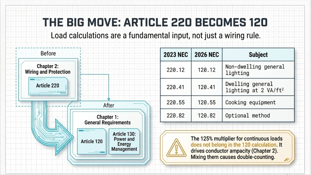
NFPA's reorganization of the Code moved the load-calculation article from Chapter 2 (Wiring and Protection) to Chapter 1 (General). The reasoning is structural: load calculations are not a wiring method or a protection rule, they are a general requirement that every subsequent article consumes. Article 110 sets the general requirements for installations, Article 120 sets how loads are calculated, and the new Article 130 sets how power and energy management systems may control those loads. The three now read in sequence.
For practitioners the most important fact is that the section suffix survived the move. Anyone who can find 220.14(I) in the 2023 book can find 120.14(I) in the 2026 book. The table below maps the sections referenced most often in dwelling and light-commercial work.
| 2023 NEC | 2026 NEC | Subject |
|---|---|---|
| 220.1 – 220.7 | 120.1 – 120.7 | Scope, general rules, nominal voltages, rounding, floor area, noncoincident loads, power control systems (120.7 is new) |
| 220.12 | 120.12 | General lighting unit loads for non-dwelling occupancies (Table 120.12) |
| — (new) | 120.13 | Minimum number of general-purpose branch circuits in dwelling units, figured at 3 VA/ft² |
| 220.14 | 120.14 | Other loads, all occupancies: receptacles at 180 VA, show windows, sign circuits, dwelling receptacles included in the unit load |
| 220.40 – 220.41 | 120.40 – 120.41 | Feeder and service calculations, general; dwelling unit general lighting at 2 VA/ft² (was 3) |
| Table 220.42(A) | Table 120.42 | Lighting load demand factors: dwelling first 3,000 VA at 100%, 3,001–120,000 VA at 35%, remainder at 25% |
| 220.44 | 120.44 | Non-dwelling receptacle loads: first 10 kVA at 100%, remainder at 50% |
| 220.50 | 120.50 | Motors: 25% of the largest motor load added per 430.24 |
| 220.51 | 120.51 | Fixed electric space heating at 100% of connected load |
| 220.52 | 120.52 | Small-appliance (1,500 VA each) and laundry (1,500 VA) branch-circuit loads |
| 220.53 | 120.53 | Four or more fastened-in-place appliances on one feeder or service: 75% of nameplate |
| 220.54 / Table 220.54 | 120.54 / Table 120.54 | Household electric clothes dryers: 5,000 VA or nameplate, whichever is larger; revised demand table |
| 220.55 / Table 220.55 | 120.55 / Table 120.55 | Household cooking appliances over 1¾ kW; Column C 8 kW for a single range up to 12 kW; Notes 1–5 |
| 220.57 | 120.57 | Electric vehicle supply equipment: larger of nameplate or 7,200 VA, at 100% |
| 220.60 | 120.60 | Noncoincident loads: use the larger of loads unlikely to operate simultaneously |
| 220.61 | 120.61 | Feeder or service neutral load; 70% for range and dryer neutrals; 70% above 200 A |
| 220.82 | 120.82 | Optional method, one-family dwelling: first 8 kVA at 100% (was 10 kVA), remainder at 40% |
| 220.83 | 120.83 | Optional method, existing dwelling unit with added loads |
| 220.84 / 220.85 | 120.84 / 120.85 | Optional method, multifamily dwellings of three or more units; two dwelling units on one service |
| 220.87 | 120.87 | Determining existing loads from recorded maximum demand |
| Article 750 | Article 130 | Energy management systems, now titled for power and energy management, with load management provisions |
Practice note
Drawings, specifications, and calculation reports issued under the 2026 edition should cite the 120-series numbers. Documents that must serve jurisdictions still on the 2023 or 2020 edition should either cite the edition in force or carry a dual citation such as "120.82 (2026) / 220.82 (2023)". Keentel's calculation templates carry both until a jurisdiction adopts the 2026 edition.
2. The General Rules of Article 120
Part I of Article 120 sets the rules every downstream calculation depends on. Most are carried over from the 2023 text, but two additions matter.
2.1 Nominal voltages, rounding, and floor area (120.5)
Calculations are performed at nominal system voltages: 120, 120/240, 208Y/120, 240, 347, 480Y/277, 480, 600Y/347, and 600 volts. Where a calculation produces a fraction of an ampere, a fraction of 0.5 or larger is rounded up and a fraction below 0.5 may be dropped. Floor area is measured from the outside dimensions of the building, apartment, or other area involved; for dwelling units the area does not include open porches, garages, or unused or unfinished spaces that are not adaptable for future use. A basement that could become living space is counted; a crawl space is not.
The 2026 text adds a clarification practitioners have argued about for years: the 125 percent multiplier for continuous loads is not part of the load calculation. Continuous loads still drive conductor ampacity and overcurrent-device ratings through 210.19, 210.20, 215.2, 215.3, and 230.42, all of which remain in Chapter 2. But the calculated load that establishes the service size under Article 120 is the load itself. Keeping those two ideas apart prevents the double-counting that occurs when a designer applies 125 percent inside the calculation and then again when selecting conductors.
2.2 Noncoincident loads (120.6) and power control systems (120.7)
Where it is unlikely that two or more noncoincident loads will operate at the same time, only the largest load contributing to the total need be used. This is the general permission behind the heating-versus-cooling rule in 120.60 and the heat-pump provisions in the optional method.
New Section 120.7 formally recognizes power control systems, listed equipment that monitors current and actively limits it to a setpoint. Where such a system controls a load or group of loads, the setpoint may be used in the calculation in place of the connected nameplate, and the setpoint is treated as the calculated load for that group. This is the code hook that allows a 200 A service to accept two 48 A EV chargers, a heat pump, and an induction range without an upgrade, provided the control system is listed for the purpose and installed per Article 130 and, for EV charging, the energy-management provisions of Article 625.
Why 120.7 matters to Keentel clients
Utility service upgrades in many territories now carry lead times measured in months and, for pad-mount transformer replacements, sometimes longer. A load calculation that recognizes a listed power control system can keep an electrification or EV project inside the existing service capacity. The calculation must document the controlled setpoint, the controlled loads, the listing, and the fail-safe behaviour of the controller. An unlisted "smart panel" does not qualify.
3. The 2 VA Rule and the New Branch-Circuit Count
3.1 General lighting at 2 VA per square foot (120.41)
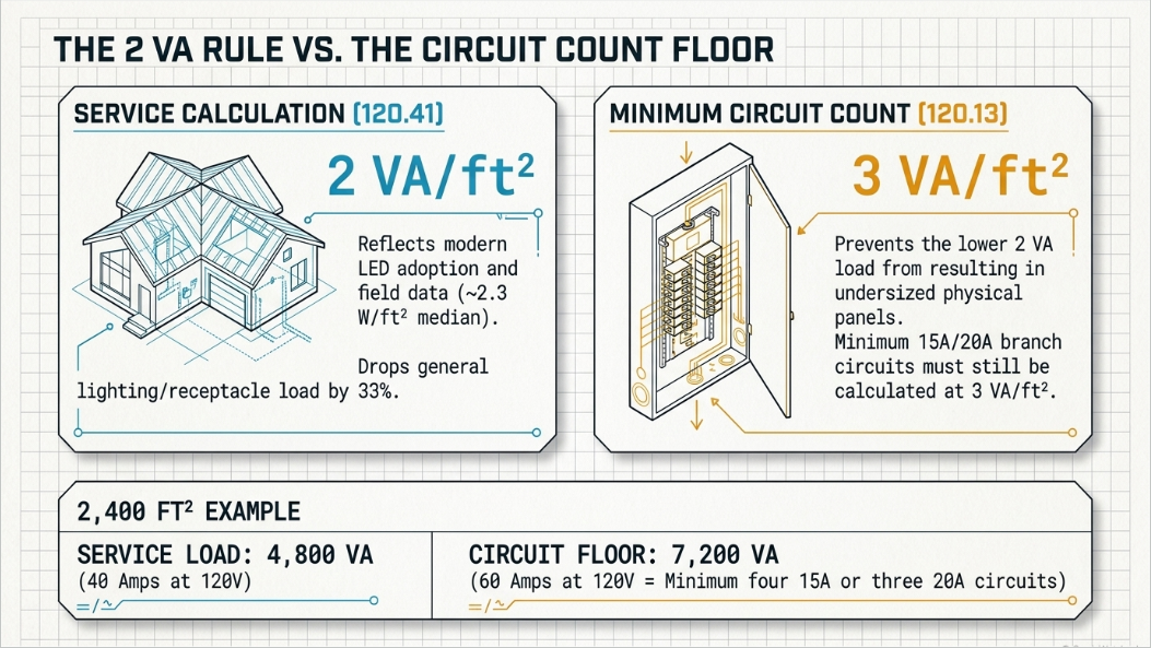
For dwelling units, the general lighting and general-use receptacle load for feeder and service calculations is now 2 VA per square foot of floor area. The 2023 value was 3 VA, a figure that had stood essentially unchanged since the era of incandescent lamps. Two things drove the change. Federal efficiency standards effectively removed general-service incandescent lamps from the market, moving residential lighting to LED sources that draw a fraction of the power. And measured data from a large sample of occupied U.S. homes, collected by the national laboratory community, showed median general lighting and receptacle density in the vicinity of 2.3 W per square foot. The Code-making panel adopted 2 VA as the new unit load for the service and feeder calculation.
In a dwelling the general-use receptacles are included in this unit load; they are not counted separately at 180 VA each. The 180 VA per receptacle rule in 120.14(I) applies to non-dwelling occupancies. The 2 VA figure flows into every dwelling method: the standard method in Part III, the optional one-family method in 120.82, the existing-dwelling method in 120.83, and the multifamily optional method in 120.84.
| Floor area (ft²) | 2023: 3 VA/ft² | 2026: 2 VA/ft² | Reduction (VA) | Reduction at 240 V |
|---|---|---|---|---|
| 1,200 | 3,600 VA | 2,400 VA | 1,200 VA | 5.0 A |
| 1,800 | 5,400 VA | 3,600 VA | 1,800 VA | 7.5 A |
| 2,400 | 7,200 VA | 4,800 VA | 2,400 VA | 10.0 A |
| 3,200 | 9,600 VA | 6,400 VA | 3,200 VA | 13.3 A |
| 4,500 | 13,500 VA | 9,000 VA | 4,500 VA | 18.8 A |
| 6,000 | 18,000 VA | 12,000 VA | 6,000 VA | 25.0 A |
The reductions in the right-hand columns are connected-load reductions before the Table 120.42 demand factor. Because everything above the first 3,000 VA of the general lighting group is taken at 35 percent in the standard method, the effect on the final service current is smaller than the table suggests: roughly 0.35 × 2,400 VA ÷ 240 V, or about 3.5 A, for the 2,400 ft² house. Under the optional method, where the remainder above 8 kVA is taken at 40 percent, the effect is about 4 A for the same house.
3.2 Section 120.13: the circuit count stays at 3 VA per square foot
The panel recognized that if the same 2 VA figure were used to determine how many general-purpose branch circuits a dwelling needs, the circuit count would fall by a third and receptacle circuits would be more heavily loaded in practice. New Section 120.13 therefore requires the minimum number of 15 A or 20 A general-purpose branch circuits to be determined at 3 VA per square foot, independent of the 2 VA service calculation. The two figures answer two different questions for the same house.
Worked example — 120.13 minimum circuit count, 2,400 ft² dwelling
Branch-circuit unit load: 2,400 ft² × 3 VA/ft²
7,200 VA
At 120 V: 7,200 VA ÷ 120 V
60 A
Minimum 15 A circuits: 60 ÷ 15
4 circuits
Minimum 20 A circuits: 60 ÷ 20
3 circuits
Plus the circuits required by 210.11(C) regardless of area: two 20 A small-appliance circuits, one 20 A laundry circuit, one 20 A bathroom circuit, one 20 A garage circuit, and any dedicated circuits required by equipment nameplates.
Design guidance
Section 120.13 is a floor, not a design target. Keentel lays out general-purpose circuits by room, receptacle count, and AFCI/GFCI grouping and then checks the total against 120.13. In practice a competently laid-out dwelling exceeds the 120.13 minimum comfortably; the section exists to stop a designer from using the 2 VA figure to justify an undersized panel.
4. Small-Appliance, Laundry, and the Lighting Demand Factor
Section 120.52 assigns 1,500 VA to each two-wire 20 A small-appliance branch circuit required by 210.11(C)(1), with a minimum of two, and 1,500 VA to the laundry branch circuit required by 210.11(C)(2). Where a dwelling has more than two small-appliance circuits, each is counted. Where a laundry receptacle is not required (for example, in a multifamily unit served by a common laundry that meets the conditions of 210.52(F)), the laundry load may be omitted.
These loads are added to the general lighting load and the sum is taken through Table 120.42. For
dwelling units the demand factors are unchanged from the 2023 edition: the first 3,000 VA at 100 percent, from 3,001 to 120,000 VA at 35 percent, and the remainder above 120,000 VA at 25 percent. The demand factor recognizes that lighting, receptacle, kitchen countertop, and laundry loads do not peak simultaneously. It applies to this group only. Ranges, dryers, fixed appliances, heating, cooling, and EV charging each have their own rules and never pass through Table 120.42.
Worked example — general lighting group, 2,400 ft² dwelling, three small-appliance circuits
General lighting: 2,400 ft² × 2 VA/ft²
4,800 VA
Small-appliance circuits: 3 × 1,500 VA
4,500 VA
Laundry circuit
1,500 VA
Connected general lighting group
10,800 VA
First 3,000 VA at 100%
3,000 VA
Remaining 7,800 VA at 35%
2,730 VA
General lighting demand (2026)
5,730 VA
Same house under 2023 (7,200 + 4,500 + 1,500 = 13,200 VA; 3,000 + 10,200 × 0.35)
6,570 VA
Two points deserve emphasis. The demand factor applies before the appliance, range, dryer, and HVAC loads are added, never to the whole-house total. And a demand factor never increases a load; where a reader sees a multiplier above 100 percent, it is the continuous-load rule for conductor sizing, which is a different concept living in a different article.
5. Fixed Appliances, Dryers, and Cooking Equipment
5.1 Fastened-in-place appliances (120.53)
Where four or more appliances fastened in place, other than ranges, clothes dryers, space-heating equipment, and air-conditioning equipment, are served by the same feeder or service in a one-family, two-family, or multifamily dwelling, a demand factor of 75 percent may be applied to their combined nameplate rating. Typical members of this group are the dishwasher, waste disposer, built-in microwave, water heater, well pump, sump pump, attic fan, and garage-door opener. With three or fewer, each is counted at 100 percent.
The group is defined by what is excluded. A range hood is a fastened-in-place appliance; a countertop microwave on a small-appliance circuit is not counted at all because it is already inside the 1,500 VA small-appliance allowance. Electric water heaters belong in this group even though they are often the largest single member.
5.2 Household clothes dryers (120.54)
Each household electric clothes dryer is counted at 5,000 VA or the nameplate rating, whichever is larger. Where a feeder or service supplies several dryers, as in a multifamily building or a laundry room, the demand factors of Table 120.54 apply. The 2026 edition revised the table for small dryer counts: the 2023 table held 100 percent through four dryers and stepped to 85 percent at five, whereas the 2026 table applies a reduced factor from the third dryer onward, reflecting the same diversity data that drove the lighting change. The table continues to decline with the number of dryers to a floor in the mid-20-percent range for very large counts. Because the small-count rows changed, designers should read the adopted 2026 table directly rather than relying on 2023 memory.
Where two or more single-phase dryers are supplied by a three-phase, four-wire feeder or service, the load is calculated on the basis of twice the maximum number connected between any two phases, exactly as for ranges.
5.3 Household cooking equipment (120.55 and Table 120.55)
Household electric ranges, wall-mounted ovens, counter-mounted cooking units, and other household cooking appliances individually rated over 1¾ kW are calculated using Table 120.55 and its notes. Appliances at 1¾ kW or below are treated as ordinary appliance loads at nameplate. The table has three columns: Column A and Column B give percentage demand factors by number of appliances for units rated under 3½ kW and from 3½ to 8¾ kW respectively, and Column C gives a maximum demand in kW for appliances rated over 8¾ kW up to 12 kW. For a single range not over 12 kW, Column C yields 8 kW.
| Table 120.55 note | Rule | Example |
|---|---|---|
| Note 1 | For ranges over 12 kW through 27 kW, all the same rating, increase the Column C value by 5% for each kW or major fraction of a kW by which the rating exceeds 12 kW. | One 14 kW range: 2 kW over → +10% → 8 kW × 1.10 = 8.8 kW. One 16.5 kW range: 4.5 kW over, rounded to 5 → +25% → 10 kW. |
| Note 2 | For ranges over 8¾ kW through 27 kW of unequal ratings, compute an average rating (treating any range under 12 kW as 12 kW) and apply Note 1 to the average. | Ranges of 12, 14, and 16 kW: average 14 kW → +10% on the Column C value for three ranges (14 kW) → 15.4 kW. |
| Note 3 | For ranges over 1¾ kW through 8¾ kW, the Column A or B percentage may be applied to the sum of nameplates instead of Column C. | Six 8 kW ranges: Column B for six units (43%) × 48 kW = 20.64 kW, versus Column C 21 kW. |
| Note 4 | Branch-circuit load for one range is per Table 120.55; one counter-mounted cooking unit and up to two wall-mounted ovens in the same room, on one branch circuit, are treated as one range of combined rating. | Cooktop 7.2 kW + two ovens 3.6 kW each = 14.4 kW → treated as a 14.4 kW range → 8 kW × 1.10 = 8.8 kW (2.4 kW over, rounded to 2). |
| Note 5 | The table also applies to household cooking appliances in instructional programs. | A school family-and-consumer-science lab with twelve 12 kW ranges uses Column C for twelve units (27 kW). |
5.4 Range and dryer neutrals (120.61(B))
Because the heating elements of ranges and dryers operate line-to-line at 240 V, only the 120 V oven lights, controls, timers, and motors return on the neutral. Section 120.61(B) permits the feeder or service neutral for household ranges, wall ovens, cooktops, and dryers to be taken at 70 percent of the demand calculated above. That reduction is one of the two available for the neutral; the other, in 120.61(C), takes the portion of the unbalanced load above 200 A at 70 percent for loads other than nonlinear loads and three-wire single-phase or two-phase systems.
6. Heating, Air Conditioning, and Motor Loads
Fixed electric space heating enters the standard method at 100 percent of the total connected load under 120.51, with no demand factor unless the authority having jurisdiction grants one for a system with demonstrated diversity or duty cycle. Air-conditioning equipment enters at its rated load; for hermetic refrigerant motor-compressors the branch-circuit selection current or rated-load current from the nameplate governs per Article 440.
Section 120.60 then permits the smaller of two noncoincident loads to be omitted, and heating versus cooling is the textbook case. In the standard method the designer includes the larger of the space-heating load or the air-conditioning load and drops the other. For a heat pump with electric resistance supplemental heat, both the compressor and the strip heat are counted unless a control prevents simultaneous operation, in which case the smaller may be omitted.
Section 120.50 adds 25 percent of the largest motor load, per 430.24, on top of the other loads. In a dwelling the largest motor is usually the air-conditioning compressor. Where the compressor has been omitted under 120.60 because heating governs, the common practice, and the one Keentel follows, is to apply the 25 percent to the largest motor that remains in the calculation, typically the waste disposer, a well pump, or a pool pump. The adder is small, but omitting it entirely is a plan-review comment waiting to happen.
Continuous loads, once more
Fixed electric space heaters are treated as continuous loads for branch-circuit sizing under 424.4(B), which is why the heater's branch-circuit conductors and overcurrent device are sized at 125 percent. That factor does not enter the Article 120 service calculation, where the heater is taken at 100 percent of connected load. Air-conditioning equipment is generally not a continuous load; its conductor sizing follows Article 440 and the nameplate minimum circuit ampacity.
7. The Standard Method, End to End
Part III of Article 120 is the standard method for feeders and services. It applies to any occupancy, and for dwellings it is the method against which the optional methods are compared. The example below is a single-family dwelling with a full set of electric appliances and a Level 2 EV charger, worked under the 2026 numbers with the 2023 result alongside.
| Item | Data |
|---|---|
| Floor area | 2,400 ft² (finished area, excluding garage and open porch) |
| Small-appliance circuits | Three 20 A circuits |
| Laundry | One 20 A circuit |
| Range | 14 kW, 240 V |
| Clothes dryer | 5.0 kW nameplate, 240 V |
| Dishwasher / disposer / built-in microwave | 1,500 VA / 800 VA / 1,200 VA, all 120 V |
| Water heater | 4,500 VA, 240 V |
| Air conditioning | Condensing unit, 28 A rated-load current at 240 V (6,720 VA) |
| Heating | 15 kW electric furnace, 240 V |
| EV supply equipment | 48 A Level 2 charger, 240 V (11,520 VA nameplate) |
| Service | 120/240 V, single-phase, three-wire |
Standard method — 2026 numbers
Step 1 General lighting group: 4,800 + 4,500 + 1,500 = 10,800 VA; Table 120.42: 3,000 + 7,800 × 0.35
5,730 VA
Step 2 Fastened-in-place appliances (120.53): 1,500 + 800 + 1,200 + 4,500 = 8,000 VA; four appliances → 75%
6,000 VA
Step 3 Clothes dryer (120.54): larger of 5,000 VA or nameplate
5,000 VA
Step 4 Range (Table 120.55, Note 1): 14 kW → 8 kW × 1.10
8,800 VA
Step 5 Heating vs. cooling (120.60): 15,000 VA heat vs. 6,720 VA A/C → heat governs
15,000 VA
Step 6 Largest motor remaining (120.50): waste disposer 800 VA × 25%
200 VA
Step 7 EV supply equipment (120.57): larger of 11,520 VA nameplate or 7,200 VA, at 100%
11,520 VA
Calculated load
52,250 VA
Service current: 52,250 ÷ 240
217.7 A → 218 A
Minimum service: next standard rating above 218 A
225 A
Same dwelling without the EV charger
40,730 VA → 169.7 A → 200 A service
The same dwelling under the 2023 numbers
General lighting group: 7,200 + 4,500 + 1,500 = 13,200 VA; 3,000 + 10,200 × 0.35
6,570 VA
Appliances, dryer, range, heating, motor (unchanged)
35,000 VA
EV supply equipment at 100%
11,520 VA
Calculated load
53,090 VA
Service current: 53,090 ÷ 240
221.2 A → 225 A service
The lighting change trimmed 840 VA and about 3.5 A from this house, which did not move it across a service-size boundary. What did move it was the EV charger: without it the dwelling sits comfortably on a 200 A service under either edition, and with it the standard method calls for 225 A. This is the pattern Keentel sees on nearly every electrification project, and it is why the optional method and the power-control-system provisions matter far more in 2026 practice than the 2 VA headline.
7.1 Neutral load for the same dwelling (120.61)
Feeder/service neutral — maximum unbalanced load
General lighting group demand (120 V loads)
5,730 VA
120 V fastened-in-place appliances: 1,500 + 800 + 1,200 = 3,500 VA × 75%
2,625 VA
Dryer: 5,000 VA × 70% (120.61(B))
3,500 VA
Range: 8,800 VA × 70% (120.61(B))
6,160 VA
Largest-motor adder (disposer, 120 V)
200 VA
Water heater, furnace, EVSE: 240 V line-to-line, no neutral contribution
0 VA
Neutral load
18,215 VA
Neutral current: 18,215 ÷ 240
75.9 A → 76 A
The neutral is well below 200 A, so the additional 70 percent reduction of 120.61(C) does not apply. The grounded service conductor must still satisfy the minimum sizes of 250.24(D) tied to the grounding electrode conductor table, which for a 225 A service with 4/0 AWG copper or 300 kcmil aluminum ungrounded conductors typically requires a 2 AWG copper or 1/0 AWG aluminum grounded conductor regardless of the calculated neutral load.
7.2 Service conductors and the 83 percent rule
Service-entrance conductors must have an ampacity not less than the calculated load per 230.42(A), and the service disconnect for a one-family dwelling must be rated not less than 100 A, three-wire, per 230.79(C). For 120/240 V single-phase dwelling services and the main power feeder to a dwelling unit, 310.12 permits the ungrounded conductors to be sized at 83 percent of the service rating, which is the origin of the familiar 2/0 AWG copper or 4/0 AWG aluminum for a 200 A dwelling service and 4 AWG copper or 2 AWG aluminum for 100 A. The 83 percent allowance is a dwelling-specific recognition of load diversity and does not extend to feeders that serve only part of a dwelling's load or to non-dwelling occupancies.
Terminations are the controlling constraint in most residential equipment. Unless the equipment is listed and marked otherwise, conductors are selected from the 60°C column of Table 310.16 for circuits of 100 A or less and the 75°C column above 100 A, per 110.14(C). A 90°C conductor may be used for adjustment and correction factors but its ampacity is capped at the termination temperature rating.
8. The Optional Method for a One-Family Dwelling (120.82)
The optional method is available for a dwelling unit with a total connected load served by a single 120/240 V or 208Y/120 V three-wire set of service or feeder conductors with an ampacity of 100 A or greater. It replaces the separate demand factors of the standard method with a single general-load factor and a menu of heating and cooling options. Under the 2023 edition its general load took the first 10 kVA at 100 percent and the remainder at 40 percent. Under the 2026 edition the 100 percent tier is 8 kVA, with the remainder still at 40 percent.
8.1 The general load, 120.82(B)
The general load is the sum of: the general lighting and receptacle load at 2 VA per square foot; 1,500 VA for each two-wire 20 A small-appliance and laundry circuit; the nameplate rating of all appliances that are fastened in place, permanently connected, or on a specific circuit, including ranges, ovens, cooktops, dryers, water heaters, and similar equipment, and including motors not part of the heating or cooling equipment; and the nameplate rating of any motor and low-power-factor loads. Ranges and dryers go in at full nameplate here, not at the Table 120.55 or Table 120.54 values. The general load is then taken at 100 percent of the first 8 kVA and 40 percent of the remainder.
8.2 Heating and air-conditioning, 120.82(C)
The designer includes the largest of the following six items, not the sum: (1) 100 percent of the nameplate of the air conditioning and cooling; (2) 100 percent of the nameplate of heat-pump compressors where there is no supplemental heat; (3) 100 percent of the heat-pump compressor plus 65 percent of the supplemental electric heat, unless a control prevents simultaneous operation, in which case the supplemental heat is omitted; (4) 65 percent of the nameplate of central electric space heating where there are fewer than four separately controlled units; (5) 40 percent of the nameplate of four or more separately controlled electric space-heating units; and (6) 100 percent of the nameplate of electric thermal storage and similar systems where the expected load is continuous at full nameplate.
8.3 EV supply equipment in the optional method
Electric vehicle supply equipment is added at 100 percent of the larger of nameplate or 7,200 VA, consistent with 120.57. It is not part of the general load and does not receive the 40 percent factor. Where a listed energy-management system controls the EVSE, the controlled setpoint may be used per 120.7 and Article 625.
Feeder/service neutral — maximum unbalanced load
General lighting group demand (120 V loads)
5,730 VA
120 V fastened-in-place appliances: 1,500 + 800 + 1,200 = 3,500 VA × 75%
2,625 VA
Dryer: 5,000 VA × 70% (120.61(B))
3,500 VA
Range: 8,800 VA × 70% (120.61(B))
6,160 VA
Largest-motor adder (disposer, 120 V)
200 VA
Water heater, furnace, EVSE: 240 V line-to-line, no neutral contribution
0 VA
Neutral load
18,215 VA
Neutral current: 18,215 ÷ 240
75.9 A → 76 A
9. Existing Dwellings: 120.83 and 120.87
Most of the load-calculation questions Keentel receives in 2026 are not about new construction. They are about whether an existing 100 A or 150 A service can accept a heat pump, an induction range, a battery system, or an EV charger. Article 120 offers two paths.
9.1 The existing-dwelling optional method (120.83)
Section 120.83 permits the total load of an existing dwelling unit to be calculated where additional loads are added, using the general load structure of the one-family optional method with its own demand factors and its own handling of heating and cooling. The 2026 edition reworked this section to distinguish between the loads that are already there and the specific classes of load being added, with different factors applied to added EV charging, added central resistance heating, and other added loads. Because the revised text departs from the familiar 2023 structure, designers should apply the adopted 2026 section directly rather than a 2023 template with the numbers changed.
9.2 Recorded maximum demand (120.87)
Section 120.87 permits the existing load to be established from the maximum demand recorded over one year, or, where a full year of data is not available, from a recording of at least 30 days that captures the peak season or is adjusted to reflect it. The existing demand is taken at 125 percent, and the new load is added at its calculated value. The 2026 text also addresses the credit that may be taken for loads that are being removed as part of the project, which is the practical case when a gas furnace and gas range are being replaced by electric equipment on a home that already has electric resistance backup.
Utility interval data, where the utility provides it, is the cleanest evidence for a 120.87 calculation. Where it is not available, a recording ammeter or power-quality logger on the service conductors for 30 days during the heating or cooling season is the usual approach. The recorded peak, times 1.25, plus the new load, is compared to the service rating.
120.87 example — adding a 48 A EV charger to a 150 A service
Recorded 12-month maximum demand from utility interval data
62 A (14,880 VA)
Existing demand at 125%
77.5 A
New EVSE at 100% of nameplate (48 A)
48 A
Total
125.5 A → 126 A
Service rating
150 A — acceptable without upgrade
Alternative if the peak had been 90 A: 112.5 + 48 = 160.5 A → exceeds 150 A; consider a listed EV energy-management system to cap the EVSE at 32 A (152.5 A, still over) or 24 A (136.5 A, acceptable), or a service upgrade.
10. Multifamily Dwellings, Two-Unit Services, and House Loads
The optional method in 120.84 applies to a multifamily dwelling of three or more units where no individual unit is supplied by more than one feeder, each unit has electric cooking equipment (or, where cooking is gas, is assumed to have an 8 kW electric range for the purpose of the calculation), and each unit has either electric space heating or air conditioning, or both. The connected load of all units combined, at 2 VA per square foot for lighting, 1,500 VA per small-appliance and laundry circuit, nameplate of all appliances, and the larger of heating or cooling in each unit, is taken through Table 120.84, whose demand factor falls with the number of units, from 45 percent at three to five units to 23 percent at 62 or more.
House loads, the corridor and site lighting, elevators, common laundry, domestic water pumps, fire pumps, and common-area HVAC, are not included in the Table 120.84 calculation. They are calculated by the standard method and added at their own values. Continuous house loads, such as 24-hour corridor lighting, drive conductor and overcurrent-device sizing at 125 percent under 215.2 and 215.3.
For two dwelling units on one service, 120.85
permits the calculation to be the larger of the sum of two individual 120.82 calculations or a 120.84 calculation for two units, rather than forcing the more conservative standard method. Individual unit feeders are calculated as single dwellings under 120.40 or 120.82; only the building service or the feeder to a group of units uses 120.84.
| Calculation | Where it applies | Method |
|---|---|---|
| Individual unit feeder | Feeder from the meter stack or house panel to one dwelling unit | Standard (Part III) or optional (120.82), 2 VA/ft² |
| Feeder to a group of units | Riser or bus serving several units, no house loads | Standard (Part III) with Table 120.42 on the combined lighting group, or 120.84 if three or more units and conditions met |
| Building service | Utility service to the whole building | 120.84 for the units plus standard-method house loads; or Part III throughout |
| House panel | Common-area loads only | Standard method; continuous loads at 125% for conductors and OCPD |
| Neutral | Any feeder or service | 120.61 only; 70% for range and dryer neutrals; 70% above 200 A where permitted |
11. EV Charging and Load Management in the 2026 Code
Electric vehicle supply equipment is the load that most often breaks a dwelling calculation, and the 2026 edition addresses it from three directions. Section 120.57 sets the calculated load at the larger of the EVSE nameplate or 7,200 VA, at 100 percent, with no demand factor for multiple units unless a listed energy-management system is used. Section 120.7 recognizes power control systems so that a controlled setpoint may be used in place of nameplate. And Article 130, which absorbed the energy-management-system provisions formerly in Article 750 and added load-management requirements, together with the EV energy-management provisions of Article 625, establishes what qualifies as such a system.
The 7,200 VA floor deserves attention. A 30 A EVSE at 240 V has a nameplate of 7,200 VA, so the floor coincides with the smallest common Level 2 unit; a 16 A unit on a 20 A circuit (3,840 VA) is still calculated at 7,200 VA. The purpose is to size the service for the charger the homeowner will eventually install, not the one the builder specified. For a 40 A charger (9,600 VA) or a 48 A charger (11,520 VA), nameplate governs.
Where several EVSE share a feeder, as in a multifamily garage, the calculated load is the sum of the nameplates at 100 percent unless a listed energy-management system limits the aggregate, in which case the system's maximum setpoint is the load. For a 50-space garage, the difference between 50 × 11,520 VA (576 kVA) and a managed setpoint of, say, 150 kVA is the difference between a new utility service with a dedicated transformer and a feeder from the existing house switchboard. Keentel's multifamily and data-center practices treat managed EV charging as a design parameter to be settled before the service is sized, not after.
Documentation the plan reviewer will expect
The EVSE nameplate and the circuit rating, and the 7,200 VA floor check.
Where a power control or energy-management system is used: the listing, the controlled loads, the maximum setpoint, the fail-safe behaviour on loss of communication, and the sections relied upon (120.7, Article 130, and Article 625 as applicable).
For existing dwellings: the 120.83 or 120.87 basis, the source of the demand data, and the removed loads credited.
12. Where Early 2026 Study Material Goes Wrong
The 2026 edition has generated a wave of exam-prep guides, calculators, and question banks. Most repeat the 2 VA and 8 kVA headlines correctly. Several of the ones we have reviewed carry errors that would produce a wrong answer on a plan review. The following are the recurring ones.
| Claim found in circulating material | What the 2026 Code actually provides |
|---|---|
| Dryer demand factors apply only when there are five or more dryers. | That was the 2023 Table 220.54 structure. The 2026 Table 120.54 applies a reduced factor from the third dryer. A four-dryer laundry room calculated at 100 percent under the 2026 edition is conservative but not what the table says; read the adopted table. |
| EV charging is counted at 100 percent of nameplate. | Correct but incomplete. Section 120.57 requires the larger of nameplate or 7,200 VA. A 16 A or 24 A EVSE is calculated at 7,200 VA, not at its nameplate. |
| Energy management systems are covered in Article 750. | In the 2026 edition the energy-management provisions were relocated to Article 130 and expanded to cover power and load management. Documents citing Article 750 under the 2026 edition are citing a number that no longer carries the requirement. |
| When heating governs under 120.60, the 25 percent largest-motor adder disappears with the air conditioner. | Section 120.50 still requires 25 percent of the largest motor load in the calculation. Once the compressor is omitted, the adder applies to the largest motor that remains, typically the disposer or a pump. |
| Article 220 was renumbered to prepare for a 2029 restructuring. | The relocation is part of the 2026 reorganization of Chapter 1 that also created Article 130. What the 2029 edition will do has not been decided and should not be cited as a reason. |
| The 120.5 rounding rule lets you round a calculated load down to the next standard service size. | Section 120.5(B) addresses fractions of an ampere only. A calculated load of 217.7 A rounds to 218 A; it does not round to 200 A. The service must be rated at least equal to the calculated load per 230.42 and 230.79. |
| Continuous loads are taken at 125 percent inside the Article 120 calculation. | The 2026 text in 120.5 clarifies that the 125 percent multiplier belongs to conductor and overcurrent-device sizing under Articles 210, 215, and 230. Applying it inside the load calculation and again when sizing conductors double-counts it. |
| The optional method's heating and cooling entry is "the larger of heat or A/C", as in the standard method. | Section 120.82(C) lists six items with different percentages, 100 percent for cooling, 65 or 40 percent for central heating, compressor plus 65 percent of supplemental heat for heat pumps, and requires the largest of the six. A 15 kW furnace enters at 9,750 VA, not 15,000 VA. |
13. Adoption Status and Transition Practice
NFPA issued the 2026 edition of NFPA 70 in the second half of 2025. Adoption is by state or local jurisdiction, and as of September 2026 the majority of jurisdictions remain on the 2023 or 2020 edition, with a small number having adopted the 2026 edition early in 2026 and others, including Texas at the state licensing level, adopting it effective in the second half of 2026. Several large states adopt on a fixed multi-year cycle that will not reach the 2026 edition until 2027 or 2028, and some jurisdictions adopt with amendments that modify or delete specific sections.
For projects that straddle the transition, Keentel recommends three practices. Confirm the edition and any local amendments in writing with the authority having jurisdiction before the calculation is issued, because the 2 VA rule alone can change a service size. Carry dual section citations on calculation sheets until the jurisdiction has adopted the 2026 edition. And where a project permitted under the 2023 edition will be inspected after the 2026 edition takes effect, confirm which edition governs the inspection; most jurisdictions apply the edition in force at permit application, but not all.
14. How Keentel Engineering Can Help
Keentel Engineering is a Florida-registered engineering firm with offices in Tampa, Austin, Sacramento, and Baltimore, providing electrical
power systems engineering from 4 kV to 765 kV and electrical-led MEP design for buildings. Our load-calculation and service-design work sits within the MEP Engineering Services and Data Center Power Engineering service lines.
| Service | What we deliver |
|---|---|
| Dwelling and multifamily load calculations | Standard and optional method calculations under the edition in force, with both methods run and the governing result documented; neutral, service-conductor, and grounding-electrode-conductor sizing; panel schedules and one-line diagrams sealed for permit. |
| Electrification and EV readiness studies | 120.83 and 120.87 assessments for existing buildings; recorded-demand analysis from utility interval data or field logging; evaluation of listed power control and energy-management systems as alternatives to service upgrades; utility service-upgrade coordination. |
| Multifamily and mixed-use service design | 120.84 building calculations with separate house-load analysis; meter-center and riser design; managed EV charging for parking structures; coordination with utility for transformer sizing and service entrance. |
| Plan-review support and peer review | Independent check of third-party load calculations against the adopted edition and local amendments; response to plan-review comments; expert review where a service size is disputed. |
| Commercial and industrial load studies | Non-dwelling calculations under Part III of Article 120, including receptacle demand under 120.44, kitchen equipment under 120.56, motor loads under Article 430, and continuous-load conductor sizing; short-circuit and coordination studies for the resulting service. |
| Code-transition consulting | Edition and amendment confirmation with the AHJ, dual-citation calculation templates, and training for design staff on the 2026 changes. |
Keentel seals the electrical design. Mechanical and plumbing design and sealing are performed by licensed specialists whom Keentel coordinates, and civil and structural work is coordinated with the appropriate registered professionals.
To discuss a project, contact Keentel Engineering at (813) 389-7871 or contact@keentelengineering.com, or schedule a 15-minute call at calendly.com/keentel-engineering/15min.
References and Further Reading
Primary sources are listed first. Links were current at publication in September 2026.
Codes and standards
- NFPA 70, National Electrical Code, 2026 edition. National Fire Protection Association, Quincy, MA, 2025. Article 120 (Branch-Circuit, Feeder, and Service Load Calculations), Article 130 (Power and Energy Management Systems), Articles 210, 215, 230, 310, 424, 430, 440, and 625.
- NFPA 70, National Electrical Code, 2023 edition. National Fire Protection Association, 2022. Article 220 and Article 750, used for the comparison figures in this guide.
- NFPA 70 2026 edition, First Draft Report and Second Draft Report, Code-Making Panel 2 (load calculations) and the Correlating Committee, 2024–2025, for the substantiation of the 2 VA unit load, new Section 120.13, and the relocation of Article 220. Available through the NFPA document information pages.
Technical basis
- Lawrence Berkeley National Laboratory, residential electrical load and service-capacity studies underpinning the 2 VA per square foot substantiation, including field data on general lighting and receptacle demand density in occupied U.S. dwellings, 2022–2024.
- U.S. Department of Energy, energy conservation standards for general service lamps, 10 CFR Part 430, effective 2023, the regulatory driver for the transition of residential lighting to LED sources.
Industry commentary
- "Changes to Dwelling Unit Calculations in the 2026 NEC," EC&M, Endeavor Business Media, 2026.
- State adoption tracking: NFPA NEC Adoption Maps and the individual state licensing-board and building-code-council notices, consulted September 2026.
Frequently Asked Questions
1. What is Article 120 in the 2026 NEC?
Article 120, Branch-Circuit, Feeder, and Service Load Calculations, is the relocated and renumbered Article 220. It contains the same parts, general rules, branch-circuit loads, feeder and service loads, optional methods, farm loads, and the specialized occupancy provisions, with the section suffixes preserved. It now sits in Chapter 1 between Article 110 and the new Article 130.
2. What is the general lighting load for a dwelling unit under the 2026 NEC?
2 VA per square foot of floor area, per 120.41, for feeder and service calculations. The 2023 figure was 3 VA per square foot. Floor area is measured from outside dimensions and excludes open porches, garages, and unfinished spaces not adaptable for future use.
3. Does the 2 VA figure change how many branch circuits a house needs?
No. New Section 120.13 requires the minimum number of general-purpose 15 A or 20 A branch circuits to be determined at 3 VA per square foot. The 2 VA figure sizes the service and feeders; the 3 VA figure sets the circuit count. Both apply to the same dwelling.
4. How much does the 2 VA change actually reduce a service?
Less than the headline suggests. In the standard method only the first 3,000 VA of the lighting group is taken at 100 percent and the rest at 35 percent, so the reduction on a 2,400 ft² house is about 840 VA, or 3.5 A at 240 V. In the optional method the remainder above 8 kVA is taken at 40 percent, and the reduction in the 100 percent tier from 10 kVA to 8 kVA largely offsets the lighting reduction.
5. Are general-use receptacles in a dwelling counted separately at 180 VA?
No. In a dwelling the general-use receptacles are included in the 2 VA per square foot unit load. The 180 VA per receptacle rule of 120.14(I) applies to non-dwelling occupancies.
6. What changed in the optional method for one-family dwellings?
The 100 percent tier of the general-load demand factor in 120.82(B) was reduced from 10 kVA to 8 kVA. The remainder is still taken at 40 percent. The general lighting component uses 2 VA per square foot. The heating and cooling options in 120.82(C) are unchanged, and EV supply equipment is added at 100 percent of the larger of nameplate or 7,200 VA.
7. Can I mix the standard and optional methods in one calculation?
No. A dwelling service or feeder calculation is completed entirely by one method. You may run both and use the compliant smaller result, and you must use the standard method for the neutral calculation and for non-dwelling loads.
8. How is an EV charger counted in a 2026 dwelling calculation?
Under 120.57, at the larger of the EVSE nameplate or 7,200 VA, at 100 percent, with no demand factor. A 48 A charger is 11,520 VA; a 16 A charger is still 7,200 VA. Where a listed energy-management or power control system limits the EVSE, the controlled setpoint may be used per 120.7 and Article 625.
9. What is a power control system under 120.7?
Listed equipment that monitors current and actively limits one or more loads to a setpoint. Where it controls a load or group of loads, the setpoint may be used as the calculated load in place of connected nameplate. The requirements for such systems are in Article 130, which replaced Article 750 in the 2026 edition, and, for EV charging, in Article 625.
10. Which demand factors apply to the general lighting group?
Table 120.42, for dwelling units: the first 3,000 VA at 100 percent, from 3,001 through 120,000 VA at 35 percent, and the remainder above 120,000 VA at 25 percent. The general lighting load, the small-appliance circuits at 1,500 VA each, and the laundry circuit at 1,500 VA are summed before the table is applied. The values are unchanged from 2023.
11. What is the 75 percent appliance demand factor and when does it apply?
Section 120.53 permits 75 percent of the combined nameplate of four or more appliances fastened in place, other than ranges, dryers, space heating, and air conditioning, served by the same feeder or service in a dwelling. With three or fewer, each is counted at 100 percent. Typical members are the dishwasher, disposer, built-in microwave, water heater, well pump, and sump pump.
12. How is a household range calculated?
Using Table 120.55. For one range rated over 8¾ kW through 12 kW, Column C gives 8 kW. For a range over 12 kW, Note 1 adds 5 percent to the Column C value for each kW or major fraction above 12 kW, so a 14 kW range is 8.8 kW and a 16 kW range is 9.6 kW. A cooktop and up to two wall ovens in the same room on one circuit are treated as one range of combined rating under Note 4.
13. What is the minimum load for an electric clothes dryer, and what changed?
Each household dryer is counted at 5,000 VA or nameplate, whichever is larger, per 120.54. The 2026 Table 120.54 revised the small-count rows so that a reduced demand factor applies from the third dryer rather than the fifth. Designers working on multifamily and laundry-room feeders should use the adopted 2026 table.
14. How are heating and air conditioning handled?
In the standard method, 120.60 permits the smaller of the two noncoincident loads to be omitted; the larger of heating at 100 percent or air conditioning at 100 percent is used. In the optional method, 120.82(C) requires the largest of six listed items with their own percentages: air conditioning at 100 percent, central electric heat at 65 percent (40 percent for four or more separately controlled units), and heat pump compressor at 100 percent plus 65 percent of supplemental heat unless interlocked.
15. Is the 25 percent largest-motor adder still required?
Yes. Section 120.50 requires 25 percent of the largest motor load, per 430.24, to be added to the feeder or service calculation. If the air-conditioning compressor has been omitted under 120.60 because heating governs, apply the 25 percent to the largest motor that remains in the calculation.
16. Does the 125 percent continuous-load factor apply inside the load calculation?
No. The 2026 text in 120.5 clarifies that continuous loads are not multiplied by 125 percent within the Article 120 calculation. The 125 percent factor applies when sizing branch-circuit, feeder, and service conductors and overcurrent devices under 210.19, 210.20, 215.2, 215.3, and 230.42.
17. How is the neutral conductor sized?
From the maximum unbalanced load under 120.61(A), which is the maximum net calculated load between the neutral and any one ungrounded conductor. Line-to-line 240 V loads such as water heaters, resistance heat, and EVSE contribute nothing. The range and dryer neutral may be taken at 70 percent under 120.61(B), and the portion of the unbalanced load above 200 A may be taken at 70 percent under 120.61(C), except for nonlinear loads and certain system configurations. The grounded conductor must also meet the minimum size of 250.24(D).
18. What is the 83 percent rule for dwelling service conductors?
Section 310.12 permits the ungrounded service or main power feeder conductors of a 120/240 V single-phase dwelling to have an ampacity not less than 83 percent of the service rating. That is why a 200 A dwelling service is commonly 2/0 AWG copper or 4/0 AWG aluminum and a 100 A service is 4 AWG copper or 2 AWG aluminum. It does not apply to feeders that carry only part of the dwelling load or to non-dwelling occupancies.
19. What are the options for an existing house that is adding load?
Section 120.83 provides an optional method for existing dwelling units with added loads, reworked in 2026 to treat added EV charging, added central resistance heating, and other added loads with their own factors. Section 120.87 permits the existing load to be established from the maximum demand recorded over one year, or from a 30-day recording capturing or adjusted to the peak season, taken at 125 percent, plus the new load at its calculated value. Both are usually more favourable than recalculating the whole house from scratch.
20. How are multifamily buildings calculated?
Under 120.84, for three or more units meeting its conditions, the combined connected load of all units at 2 VA per square foot, 1,500 VA per small-appliance and laundry circuit, all appliance nameplates, and the larger of heating or cooling per unit is taken through Table 120.84, whose factor declines from 45 percent at three to five units to 23 percent at 62 or more. House loads are calculated separately by the standard method and added. Two dwelling units on one service may use the larger of two 120.82 calculations or a two-unit 120.84 calculation per 120.85.
21. Are house loads included in the Table 120.84 demand factor?
No. Corridor and exterior lighting, elevators, common laundry, pumps, and common-area HVAC are calculated by the standard method and added at their own values. Continuous house loads drive conductor and overcurrent-device sizing at 125 percent under 215.2 and 215.3.
22. Which method gives the smaller service?
It depends on the load mix. For all-electric homes with resistance heat and many appliances, the optional method usually gives the smaller service because it takes 65 percent of central heating and 40 percent of appliance nameplates above the 8 kVA tier. For small gas-heated homes with few appliances the standard method can be smaller. Run both.
23. Which states have adopted the 2026 NEC?
As of September 2026, a small number of states adopted the 2026 edition in the first half of 2026 and others, including Texas at the state licensing level, adopted it effective in the second half of the year. Most jurisdictions remain on the 2023 or 2020 edition, and several large states will not reach the 2026 edition until 2027 or 2028. Always confirm the edition and any local amendments with the authority having jurisdiction before issuing a calculation.
24. Did anything change for non-dwelling load calculations?
The non-dwelling provisions moved with the article, so Table 120.12 for general lighting unit loads by occupancy, 120.14 for other loads including 180 VA receptacles, 120.44 for the receptacle demand factor of 100 percent on the first 10 kVA and 50 percent on the remainder, and 120.56 for commercial kitchen equipment all carry their 2023 substance under the new numbers. The general rules in 120.5 and the power-control-system recognition in 120.7 apply to all occupancies.
25. Can Keentel Engineering prepare or review a load calculation for permit?
Yes. Keentel prepares and seals electrical load calculations, service and feeder sizing, panel schedules, and one-line diagrams for dwellings, multifamily buildings, commercial and industrial facilities, and data centers under the edition in force in the project jurisdiction, and provides independent peer review of third-party calculations. Contact us at (813) 389-7871 or contact@keentelengineering.com.
Disclaimer
This document is published by Keentel Engineering for general technical information and educational purposes. It is not a substitute for the adopted text of NFPA 70, the National Electrical Code, as amended and enforced by the authority having jurisdiction for a specific project, and it does not constitute engineering services, a code interpretation, or a sealed design for any project. Section numbers, table values, and demand factors cited are stated to the best of Keentel's knowledge of the 2026 edition as published; readers must verify every value against the edition and amendments adopted in their jurisdiction before relying on it.
The worked examples are illustrative. They do not describe any specific client, site, project, product, utility, or authority having jurisdiction, and the equipment ratings used are representative values chosen to demonstrate the method. Actual calculations must use the nameplate data, floor areas, and utility and jurisdictional requirements of the project concerned.
Statements about state and local adoption of the 2026 edition reflect publicly available information as of September 2026 and change frequently. Confirm adoption status and local amendments with the authority having jurisdiction.
Keentel Engineering provides electrical engineering services. Mechanical and plumbing design and sealing are performed by licensed specialists coordinated by Keentel. Civil, structural, and geotechnical work is coordinated with the appropriate registered professionals. Nothing in this document should be read as implying that Keentel holds licensure in any discipline other than those it states.
National Electrical Code and NEC are registered trademarks of the National Fire Protection Association, Quincy, MA. Keentel Engineering is not affiliated with, endorsed by, or sponsored by the National Fire Protection Association, Lawrence Berkeley National Laboratory, the U.S. Department of Energy, any publisher named in the references, or any manufacturer of the equipment types discussed. Product and organization names are used for identification only.
Keentel Engineering makes no warranty, express or implied, as to the accuracy, completeness, or fitness for any purpose of the information in this document, and accepts no liability for any loss arising from its use. Readers requiring a calculation for a specific project should engage a licensed professional engineer in the project jurisdiction.
State of Florida — Registry No. 36853, KEENTEL LLC, DBA: KEENTEL ENGINEERING. Copyright 1995–2026 Keentel Engineering. All Rights Reserved. This document is original work of Keentel Engineering and may not be reproduced, distributed, or adapted without written permission, except for brief quotation with attribution.
| Head Office — Tampa | Austin | Sacramento | Baltimore |
|---|---|---|---|
| 400 N Ashley Dr STE #2600 | 5900 Balcones Drive STE 100 | 1401 21st St Ste R | 306 W Redwood St STE 200 |
| Tampa, FL 33602 | Austin, TX 78731 | Sacramento, CA 95811 | Baltimore, MD 21201 |
| (813) 389-7871 | (512) 591-0752 | (916) 913-4524 | (410) 225-2181 |

About the Author:
Sandip "Sonny" R. Patel, P.E.
IEEE Senior Member · Founder & CEO, Keentel Engineering
In 1995, Sonny Patel earned his Electrical Engineering degree from the University of Illinois. But degrees don't build legacies — action does.
For three decades, he has worked the power industry from every side of the table: 16 years as a utility engineer at Exelon/Commonwealth Edison; generation leadership across hydroelectric, industrial steam turbine, and a 9 GW renewable fleet; NERC Regional Entity Senior Compliance Engineer and Audit Team Lead, auditing some of the nation's largest utilities; and testing and commissioning lead on equipment up to 765 kV — the very top of the North American grid.Utility. Generator. Regulator. Consultant. Few engineers have seen all four seats. Fewer still have sat in them.
His experience spans nuclear, hydro, conventional generation, renewables, oil and gas, mining — and today's data centers, where he is authoring a three-book series on data center design. He is a Licensed Professional Engineer in six states and a Licensed Electrical Contractor in Florida (Unlimited EC) — he doesn't just design the work; he's qualified to stand behind its execution.Today, as Founder and CEO of Keentel Engineering, Sonny leads a nationwide team of engineers delivering substation design, power system studies, NERC compliance, and commissioning — done right, coast to coast.Three decades. Every side of the table. One standard: accountable engineering.
Services

Let's Discuss Your Project
Let's book a call to discuss your electrical engineering project that we can help you with.
About the Author:
Sandip "Sonny" R. Patel, P.E.
IEEE Senior Member · Founder & CEO, Keentel Engineering
In 1995, Sonny Patel earned his Electrical Engineering degree from the University of Illinois. But degrees don't build legacies — action does.
For three decades, he has worked the power industry from every side of the table: 16 years as a utility engineer at Exelon/Commonwealth Edison; generation leadership across hydroelectric, industrial steam turbine, and a 9 GW renewable fleet; NERC Regional Entity Senior Compliance Engineer and Audit Team Lead, auditing some of the nation's largest utilities; and testing and commissioning lead on equipment up to 765 kV — the very top of the North American grid.
Utility. Generator. Regulator. Consultant. Few engineers have seen all four seats. Fewer still have sat in them.
His experience spans nuclear, hydro, conventional generation, renewables, oil and gas, mining — and today's data centers, where he is authoring a three-book series on data center design. He is a Licensed Professional Engineer in six states and a Licensed Electrical Contractor in Florida (Unlimited EC) — he doesn't just design the work; he's qualified to stand behind its execution.
Today, as Founder and CEO of Keentel Engineering, Sonny leads a nationwide team of engineers delivering substation design, power system studies, NERC compliance, and commissioning — done right, coast to coast.Three decades. Every side of the table. One standard: accountable engineering.
Leave a Comment
Thank you for contacting us.
We will get back to you as soon as possible.
We will get back to you as soon as possible.
Oops, there was an error sending your message.
Please try again later.
Please try again later.
Related Posts
By SANDIP R PATEL
•
October 20, 2026
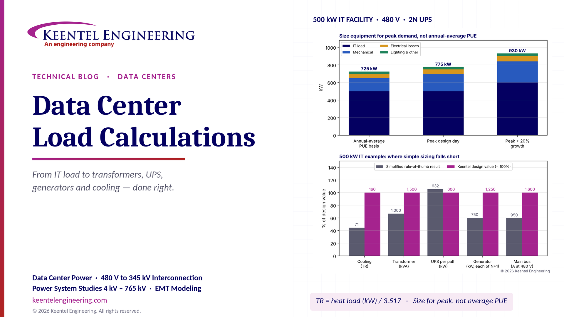
Learn data center electrical load calculations, including IT demand, PUE, UPS and generator sizing, cooling loads, redundancy, and worked US examples.
By SANDIP R PATEL
•
October 20, 2026
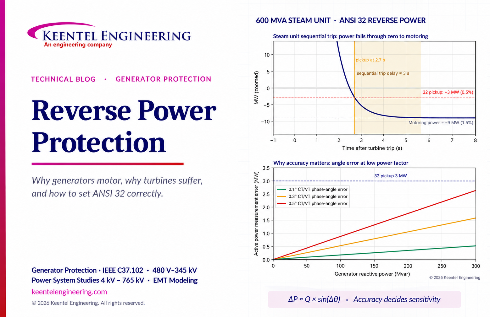
Learn reverse power protection (ANSI 32), generator motoring, relay pickup settings, time delays, sequential tripping and testing for US power plants.
Copy

By Team 2 Dexora
•
October 20, 2026
Explore grounding system testing with Keentel Engineering. Learn IEEE 80/81 methods, soil resistivity, ground resistance, and touch and step voltage safety.

By SANDIP R PATEL
•
October 13, 2026
Plan data center capacity with land screening, MW-per-acre estimates, grid power availability and interconnection feasibility studies from Keentel Engineering.

By SANDIP R PATEL
•
October 11, 2026
Learn which fault produces the highest current at a bus, why SLG faults can exceed three-phase faults, and how symmetrical components determine fault duty.

By SANDIP R PATEL
•
October 11, 2026
Learn why zero-sequence current pulsates in the dq0 frame, how Park's transformation works, and how inverter controls handle unbalance and ground faults.

By SANDIP R PATEL
•
October 11, 2026
Explore grid inertia, RoCoF and frequency response, with swing equation calculations, frequency nadir analysis and US power system simulation examples.

By SANDIP R PATEL
•
October 11, 2026
Learn transient stability analysis, swing equation, equal-area criterion and critical clearing time with a 345 kV worked example and NERC TPL-001 guidance.

By SANDIP R PATEL
•
October 11, 2026
Learn why inverter controls become unstable in weak grids, how PLL bandwidth and SCR affect stability, and how PSCAD EMT studies identify and mitigate oscillations.





