


Learn how switching overvoltage studies, insulation coordination, surge arrester assessment, and PSCAD/EMTDC modeling protect EHV systems.
Learn how Concurrent EMTDC uses data parallelism, task parallelism, PSCAD, and high-performance interconnects to accelerate EMT simulation studies.

Learn the complete substation electrical design process, including 30%, 60%, 90%, and IFC deliverables, engineering reviews, grounding, protection, and interconnection requirements.
FERC accepted PJM's Expedited Interconnection Track on June 9, 2026. Learn the eligibility rules, financial requirements, state siting commitment, and engineering checklist for the 10-month fast lane to a signed GIA.
Estimate interconnection costs before entering the queue. Learn how network upgrade costs, POI costs, and feasibility studies impact project success.
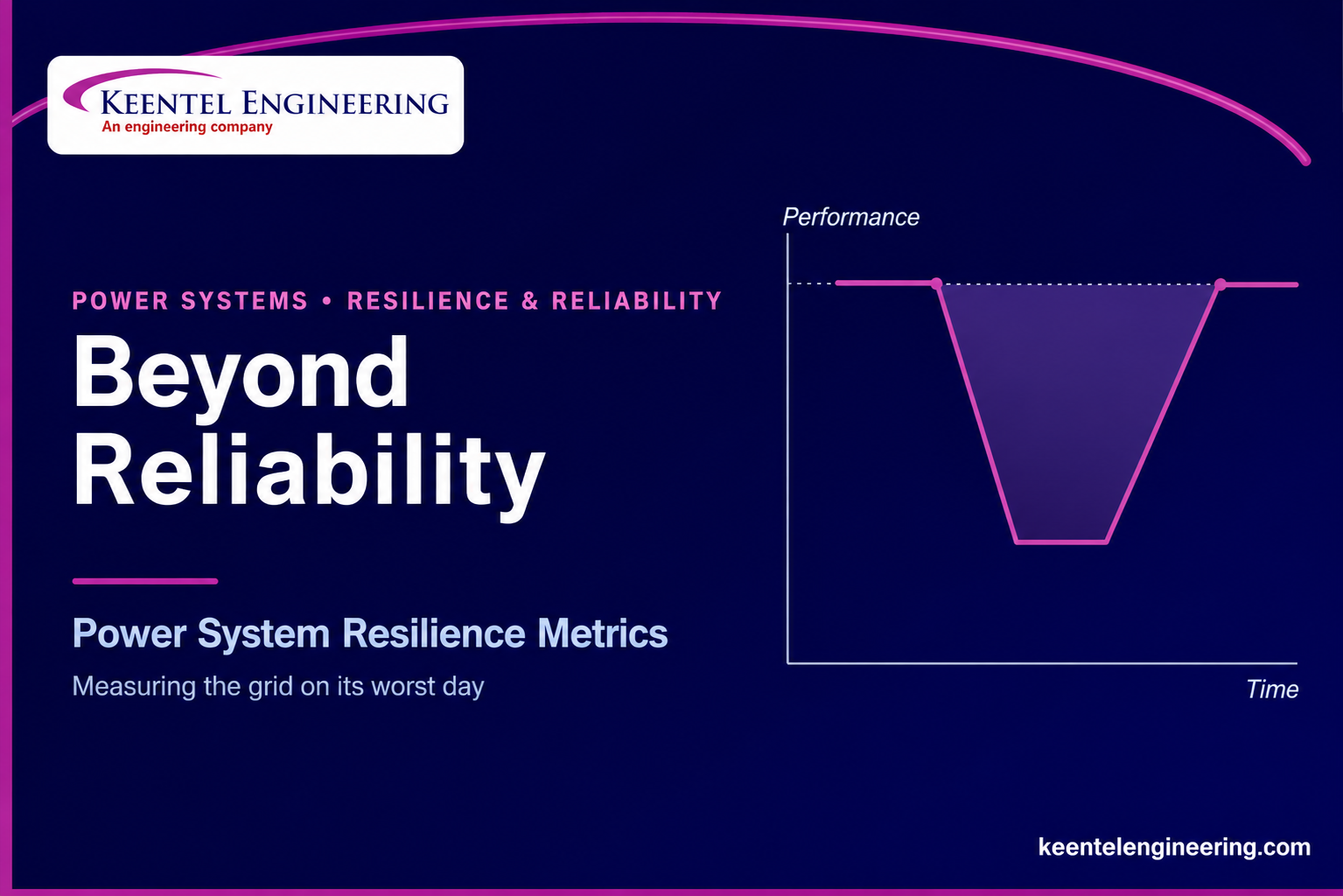
Learn how power system resilience metrics measure grid performance during extreme events. Discover resilience assessment methods and practical applications.
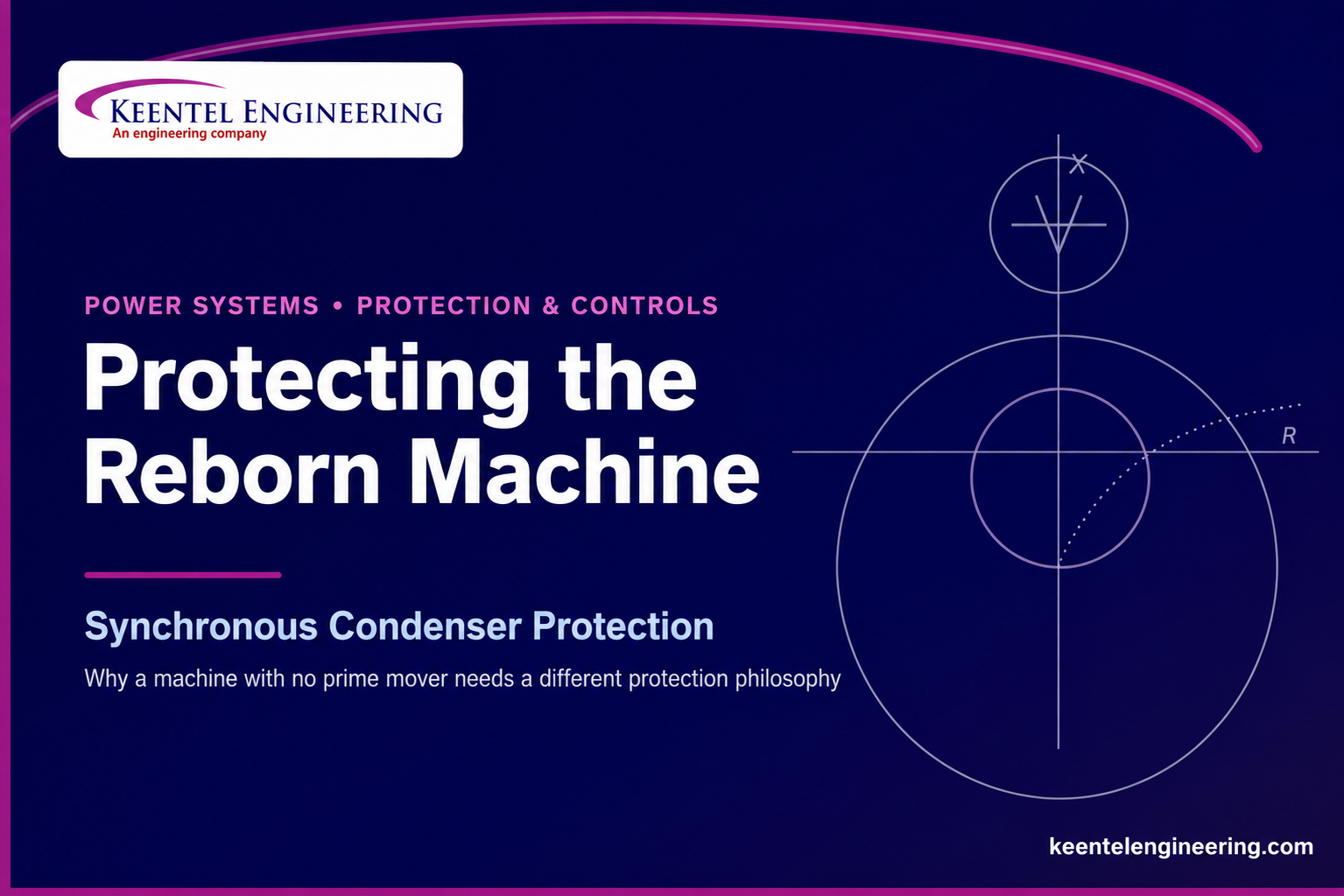
Learn synchronous condenser protection, loss of field settings, NERC PRC compliance, and protection philosophy. Discover expert engineering guidance.
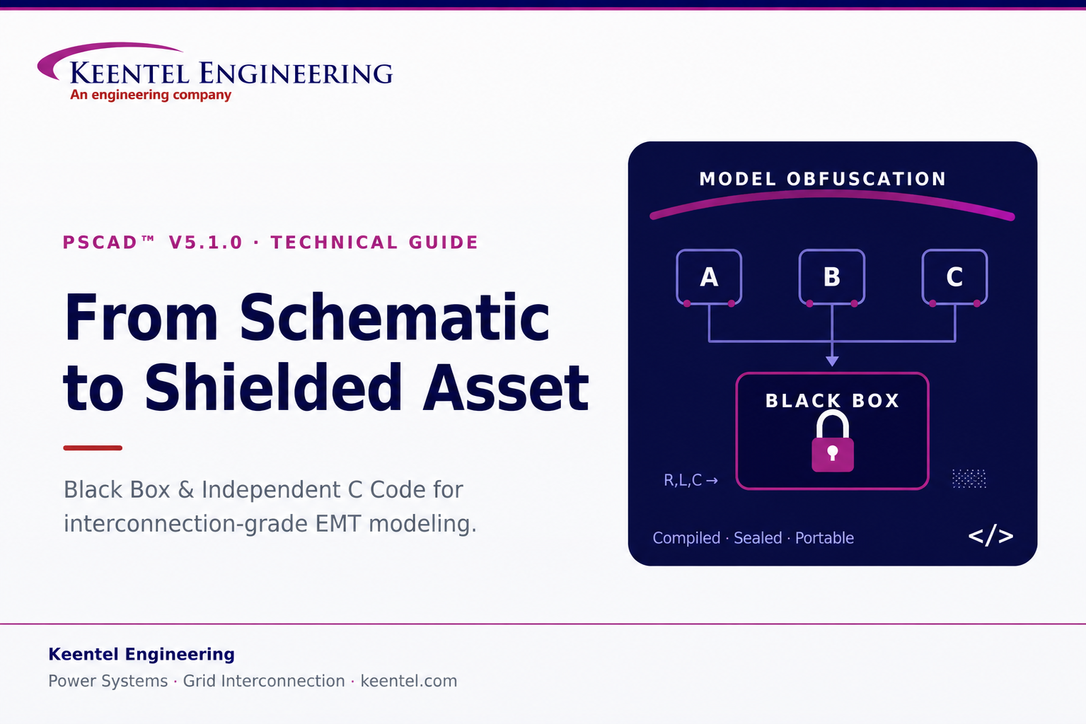
Learn how PSCAD Black Box and Independent C Code protect EMT models, secure control IP, and support interconnection-grade studies. Discover more.
Learn transmission line modeling in PSCAD, compare Bergeron and frequency-dependent models, validate the Ferranti effect, and improve EMT studies.


