
A Coordinated Electric System Interconnection Review—the utility’s deep-dive on technical and cost impacts of your project.
Challenge: Frequent false tripping using conventional electromechanical relays
Solution: SEL-487E integration with multi-terminal differential protection and dynamic inrush restraint
Result: 90% reduction in false trips, saving over $250,000 in downtime
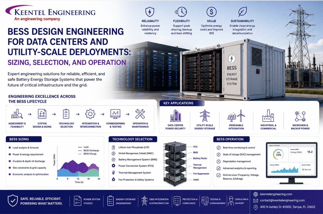
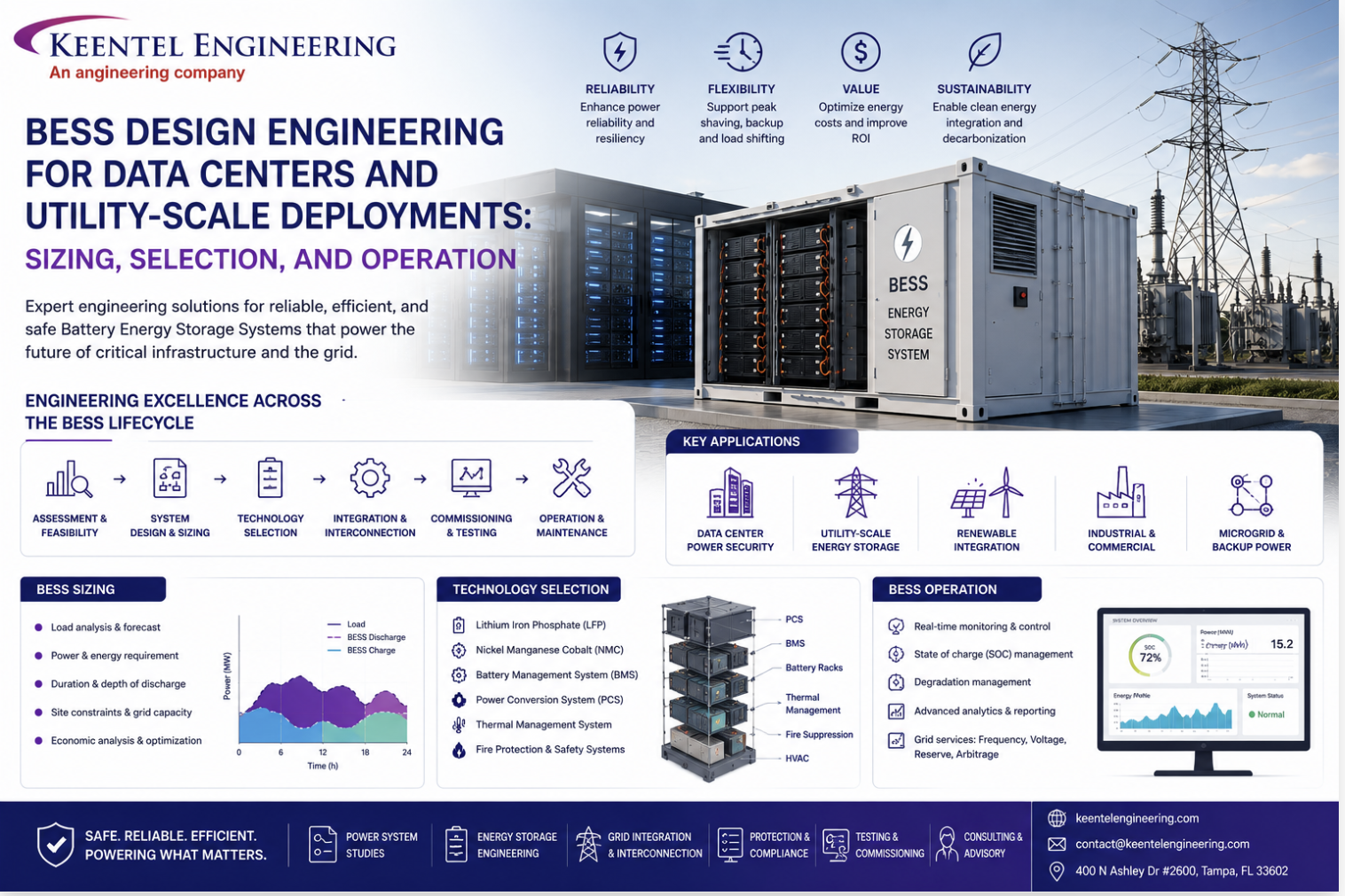
BESS Design Engineering for Data Centers and Utility-Scale Deployments: Sizing, Selection, and Operation
May 30, 2026 | Blog
Why BESS Is Now Core Infrastructure for Data Centers and the Grid
The conversation around Battery Energy Storage Systems has shifted dramatically in the last few years. What was once an auxiliary technology — useful for solar smoothing or peak shaving — is now a load-bearing part of two of the fastest-growing infrastructure segments in the world: AI data centers and utility-scale grid services.
For data centers, BESS is the bridge between unreliable transmission timelines and immediate megawatt demand. For utilities, BESS is how the grid absorbs intermittent renewables and provides synthetic inertia and spinning reserve in a generation mix that's increasingly inverter-based.
Either way, the engineering decisions made at the FEED stage — grid connection topology, battery dimensioning, DC link architecture, safety design — determine whether the system delivers on its commercial promise or becomes a stranded asset. This blog walks through every one of those decisions, from cell-level voltage curves to evacuation planning, and closes with three anonymized case studies and a technical FAQ.
Glossary of Terms
| Acronym | Term | Description |
|---|---|---|
| SOC | State of Charge | The level of battery energy stored, as a percentage of capacity |
| SOH | State of Health | The current battery capacity versus beginning-of-life performance |
| BESS | Battery Energy Storage System | A complete system: AC drive, battery bank, and control hardware/software |
| PMS | Power Management System | The system controlling a facility's electrical switching, generation, and large loads |
| DOD | Depth of Discharge | How deeply the batteries have been discharged; effectively (1 – SOC) |
| EOL | End of Life | Batteries that have reached the end of their design lifetime |
| BOL | Beginning of Life | Newly manufactured batteries with no SOH degradation |
| BMS | Battery Management System | The supervisory controller for cells, modules, strings, and arrays |
| FMECA | Failure Modes, Effects and Criticality Analysis | A reliability engineering methodology |
1. Grid Connection Engineering
The grid connection point must be decided early in the design phase. For a hyperscale data center campus or utility-scale BESS, it is often advantageous to split the BESS into two or more distinct units connected at multiple points in the network — this allows sections to operate independently with BESS support and provides redundancy against single-point failures.
LV vs. MV Connection
Most Battery Energy Storage Systems (BESS) do not exceed 1500 V DC. Going higher pushes the system into the HV classification range, which dramatically increases equipment costs and operational requirements — and DC switchgear rated for higher voltages and currents is difficult to source. Typical drive DC link voltages sit between 900–1100 V.
For grid-facing applications, the DC link voltage must be above the peak grid voltage. For a 690V AC system, the wave peak is approximately 950V, so the DC link should be kept above 1000V to operate without uncontrolled reverse conduction through the inverter switching bridge.
LV Connection: The BESS can be treated similarly to a generator incomer, though energy flow is bi-directional. Depending on AC drive configuration, the BESS may be connected to the network before the output is modulating, with the drive performing a flying synchronization. Otherwise, conventional synchronization is required.
MV Connection: A transformer is required to interface the LV drive to the MV network. This introduces several engineering decisions:
- Will the BESS energize the transformer before grid connection? If yes, conventional synchronization techniques for live/live connection are needed. If no, true black-start capability may not be possible.
- How will synchronization be controlled? Either conventional pulse-based synchro relays for frequency and voltage matching, or VT direct-measured voltage feedback from transformer primary and MV bus, letting the BESS controller perform its own synchronizing.
Transformer winding ratios must allow the BESS to stay connected at all expected MV bus operating voltages — consider voltage regulation under full-load charging and discharging, and consider optimized voltage ratios that may permit lower DC link voltages than direct connection would.
2. Dimensioning the Battery Bank
Battery dimensioning is the single most impactful design decision in a BESS. It determines both the power capability (peak charge/discharge in MW) and the energy capacity (MWh). These two are highly correlated but can be tuned independently.
Working with a battery specialist, the project engineer builds a usage profile — a programmatic description of expected charge/discharge cycles over the asset's life. An illustrative profile might include:
- 300 events per year of cycling between 60–40% SOC at 1C
- 5 events per year of spinning reserve discharge from 80–20% SOC at 2C
- 1 event in 5 years of full discharge from 90–10% SOC at 2C
- All across a
10-year design life
From this profile, the supplier specifies a battery size and configuration that can sustain the required C rating, DOD, and lifecycle while still meeting requirements at end of life (not just BOL).
This is critical: battery life predictions rest on assumptions — consistent room temperature, no abuse, the actual load profile matching the design profile. Abuse includes storage at extreme temperatures, excessive over- or under-charging, and exposure to voltage spikes. When these assumptions break, EOL arrives early.
3. Battery Topology: Cells, Modules, Strings, Arrays
Different suppliers use different terminology, but the standard hierarchy is:
- Cell — the smallest unit; a single lithium-ion electrochemical unit. Typical voltage range: 2.2 – 4.4V across the extremes of SOC (exact values depend on cell chemistry).
- Module — cells assembled in series. Typical module voltage: around 50V.
- String — modules in series, sized to the final DC link voltage. Example: 21 × 50V modules = nominal 1050 V DC.
- Array — multiple strings in parallel. A typical BESS has several arrays.
Each level has its own protection:
- Individual modules have fuses and contactors to disconnect on internal faults (e.g., overheating).
- Strings have fuse protection.
- Arrays have collective load breaker switches for maintenance isolation.
Critical design choice: Decide at FEED whether you want the ability to operate the BESS at reduced capacity by isolating an array. This is invaluable for maintenance, partial failure recovery, and — for high-availability data centers — physical separation across multiple rooms to mitigate common-mode failures like fire.
4. State of Charge (SOC) vs. State of Health (SOH)
In consumer applications, manufacturers often hide the true SOC from users — an electric vehicle displaying "0%" or "100%" may actually be operating between 20% and 80% of true SOC, with the visible range dynamically adjusted as the battery ages. This protects battery life and gives users a consistent experience as SOH degrades.
Industrial BESS cannot operate this way. Operators need to know the true state of equipment to safely extract maximum performance, plan maintenance, and schedule replacement.
What matters for a BESS is not SOC in isolation but the useful energy available at that SOC. As SOH degrades, the same % SOC represents less energy. A spinning reserve operation that worked between 80–20% SOC at BOL may need to expand to 85–15% SOC after several years of operation to deliver the same MWh.
Tracking SOH Over Time
- Operators should log SOC usage for given operations, with automated SCADA or BMS data collection to identify trends.
- Periodic dedicated SOH tests — controlled charge/discharge cycles comparing SOC against measured energy — give accurate ageing data and can flag faster-than-expected degradation.
- For installations with multiple BESS units, SOH tests can be performed by exchanging energy between systems, eliminating the need for resistive load banks. At utility scale this saves substantial OPEX — load bank testing at 8 MW can cost $1,000–$1,200 USD per hour in fuel alone, before rental and connection.
5. Black-Start Considerations
If the BESS is intended for black-start operations (energizing a dead facility from stored battery energy), three engineering elements must be addressed:
5.1 Control Circuit Power Source
Control power is normally provided by facility UPS supplies, but it is possible to take supply from one of the battery strings or arrays. If this path is chosen, any AC motor options on the drive (cooling fans, cooling pumps) must be swapped to DC motors with appropriate power supplies — typically converting high DC string voltage down to 24V DC for control.
5.2 DC Link Pre-Charge
The AC drive DC link has large capacitors for filtering and smoothing. From a fully de-energized state, these capacitors cannot be charged by a direct low-impedance connection — the sudden inrush would damage them. Pre-charge is a process of slowly energizing the capacitors using in-line current limiting resistors or controlled charging circuits until the link reaches a voltage where it can safely be connected to high-power, low-impedance sources. For black-start from battery power, a dedicated pre-charge system must be designed in.
5.3 Transformer Magnetization
The AC drive is typically capable of magnetizing its own transformer by applying a ramped voltage — this avoids the saturation effects and zero-crossing closing issues that occur with normal AC energization. The protection and switchgear must be engineered to keep the transformer primary disconnected from the main grid until voltage has stabilized.
6. Battery Safety Design
Lithium-ion battery risks are well understood by specialists, but industry-wide operational experience is still maturing compared to legacy technologies like lead-acid.
6.1 Electrical Hazards
Working with lithium-ion batteries carries similar electrical risks to other LV battery systems: the battery terminal voltage cannot be turned off, and any short circuit is backed by a high-current, low-impedance source. Standard arc-flash PPE and lockout/tagout procedures apply.
6.2 Thermal Runaway
The defining lithium-ion-specific hazard is thermal runaway. If a cell exceeds a critical temperature — from internal short circuit, external fire, or abuse — the cell chemistry enters a self-sustaining exothermic reaction with a positive feedback loop. Worse, the reaction generates its own oxygen, making the fire extremely difficult to extinguish. Often the only available response is thermal management to prevent propagation to adjacent packs.
Modern designs mitigate this through:
- Segregating frame structures between modules
- Exhaust ducting to extract toxic gases
- "Inherently safe" cell-level designs where thermal events cannot propagate to neighboring cells
The smoke generated in a thermal runaway is highly toxic. Evacuation is the default response, with re-entry only after proper ventilation and with appropriate breathing PPE (e.g., Lithium Fire Intervention Masks).
6.3 Thermal Management
Two cooling options: air-cooled and water-cooled. Each has tradeoffs. Water-cooled systems have suffered well-documented failures where leaks caused short circuits, electrical fires, and eventual thermal runaway. Air-cooled systems are simpler but limited in heat rejection capacity at higher C rates.
7. Battery Room Design
For all of the above reasons, the batteries should occupy a dedicated room — never adjacent to control rooms or other critical areas.
Engineering and commissioning sequencing matters:
- All fire detection, fire suppression, and gas extraction systems must be installed and commissioned before batteries are placed.
- Cabling and battery rack frames can be installed in parallel with safety system commissioning.
- DC cable length to the AC drive must be considered — long runs introduce voltage drop and impose copper costs.
- Location should be such that, in the event of a fire, automatic suppression activates while personnel evacuate and the room can be sealed and ventilated safely.
For utility-scale outdoor BESS, the same principles apply at containerized scale: separation between containers, segregated cooling, dedicated fire suppression per container, and stand-off distances from substations and control buildings.
8. Direct-Connected vs. Indirectly-Connected DC Link
This is one of the most consequential architectural decisions in BESS design.
8.1 Direct-Connected DC Link
Batteries are electrically connected directly to the DC link of the AC drive, with no active components between them. The DC link voltage floats at the battery bank voltage.
Advantages:
- Lower cost (no DC-DC converter)
- Smaller installation footprint
- Higher round-trip efficiency
Disadvantages — all related to lack of DC link voltage control:
The DC link voltage is dictated by battery SOC and dynamic battery terminal voltage. This creates two compounding effects:
- SOC effect: The cell voltage curve is steep at the extremes — at high SOC the cell voltage spikes upward; at low SOC it collapses downward. This sets hard limits on the usable SOC operating range.
- Dynamic effect: During discharge, the battery's internal resistance creates a voltage drop proportional to current draw — this appears as an instantaneous drop in DC link voltage. During charging, the opposite occurs: instantaneous rise in DC link voltage proportional to charging current.
Practical consequence: A direct-connected BESS at low SOC cannot source large power (DC link voltage may collapse and the drive disconnects). At high SOC it cannot sink large power (DC link overvoltage may damage capacitors or trigger protection trips). This forces the operator to anticipate required power flows and pre-position SOC accordingly.
Additionally, balancing voltage between multiple parallel strings is difficult in direct-connected systems, which generally limits topology to single-string arrays.
8.2 Indirectly-Connected DC Link (with DC-DC Converter)
A DC-DC converter sits between the battery array and the AC drive DC link.
Advantages:
- Fully controllable DC link voltage decoupled from battery SOC and dynamic terminal voltage
- Wider usable SOC range
- Multiple battery arrays can be connected in parallel via separate DC-DC converters — even when arrays are at different voltages or SOCs
- SOC balancing between arrays is possible through converter control
- Arrays can be serviced or isolated for damage while the BESS continues operating at reduced capacity
- DC-DC converter can perform DC link pre-charge — eliminating need for a separate pre-charge circuit
- Alternative DC sources (hydrogen fuel cells, variable-speed PMG shaft generators) can be paralleled onto the DC link
Disadvantages:
- Higher cost
- Larger footprint and additional HVAC/cooling load
- Reduced round-trip efficiency (even highly efficient 98–99% DC-DC converters introduce continuous losses during both charging and discharging)
- Quiescent losses grow with converter size
- Adds failure modes (mitigated by parallel array architecture)
8.3 Architectural Recommendation by Application
- Small, single-purpose BESS with predictable load profile and tight SOC management → direct-connected is often sufficient and cost-effective.
- Data center BESS with high availability requirements, multi-array redundancy, and unpredictable load curves → indirect-connected is almost always justified.
- Utility-scale BESS with multiple service stacking (frequency regulation, energy arbitrage, capacity reserve) → indirect-connected for the operational flexibility.
9. Operational Considerations
9.1 Pre-Conditioning for Operating Modes
Different operating modes demand different SOC ranges:
- Energy regeneration (capturing process or surplus energy) → needs low pre-event SOC to absorb the incoming energy.
- Spinning reserve / capacity reserve → needs high pre-event SOC to deliver the contracted MWh.
- Frequency regulation → needs mid-range SOC with symmetric headroom both directions.
Pre-conditioning can be automated via PMS functions that drive the BESS to the correct SOC for the upcoming operation, or procedural — written operator procedures. Each has tradeoffs: PMS automation costs more in EPCIC time but removes human error; written procedures are flexible but only as good as the operators following them.
9.2 Thermal Events and Damage Inspection
After a thermal event, damage assessment must precede any return to service, and the battery supplier should be contacted for guidance.
- If the event was isolated to a single module by BMS action, damage may be limited. The BMS identifies the faulty module. After confirming the room is well-ventilated and the event is contained, personnel can enter (with breathing PPE and air quality measurement) and remove the module.
- Lithium thermal events can smolder for extended periods. Even a module that appears stable may flare up. A plan must exist for rapidly removing faulty modules to a quarantine area — water bath, fire-safe enclosure, or dedicated quarantine zone.
- Once removed, other modules can be inspected and their BMS data and terminal voltages checked. If healthy, a replacement module can restore service.
- If the fire is extensive, ESD and full evacuation is the only acceptable response. Damage assessment waits for the fire to fully burn out.
9.3 Emergency Shutdown (ESD)
A BESS ESD must disconnect all battery connections — at the string level and at the module level. Well-engineered systems offer ESD-compatible options at procurement; verifying this is a key part of vendor selection.
Restart sequencing must also be designed: fire suppression and detection systems must be back online before the BESS is re-energized, and the correct reconnection sequence (module-level → string-level → array-level → DC link → AC) must be followed.
9.4 Evacuation Planning
For lithium fires, evacuation is the default. Key planning considerations:
- Gas extraction systems for batteries in confined spaces.
- Upwind meetup points — evacuating personnel should be trained to move upwind of the fire to avoid smoke inhalation.
- Multiple meetup points depending on wind direction.
- Breathing PPE rated for lithium smoke for any personnel who must remain in the area (fire wardens, emergency response).
9.5 Adjusting Control Parameters as Batteries Age
SOH degradation forces operational adjustments over time:
- Target SOC ranges must be updated as available energy at a given SOC declines.
- High-power discharge scenarios become more thermally stressful as internal resistance rises — cooling system limits may shorten allowable high-power durations.
- Operating procedures should be revisited periodically to confirm the BESS can still meet all intended use cases at current SOH.
9.6 Long-Term Shutdown
If a BESS is being taken offline for extended periods, isolating from the main power connection is not enough. The BMS at the module level continues to draw small amounts of energy from the module itself, and over months this
can drain modules below their safe minimum voltage — permanently damaging them.
Every manufacturer publishes a long-term storage procedure including:
- Ideal storage SOC
- Acceptable temperature range
- How to disable the BMS to prevent self-discharge
- Periodic cell voltage check intervals
Following this procedure is essential. Failing to do so on an entire array can write off millions of dollars in batteries.
Three Anonymized Case Studies
Case Study 1: Hyperscale AI Data Center — BESS as a Bridge to Firm Transmission Service
Project profile: A 400 MW hyperscale AI data center campus contracted firm transmission service from the local utility, with an expected service date approximately four years after groundbreaking. The developer needed first-MW operations within 18 months — a 30-month gap to bridge.
Engineering challenge: The campus had access to a 100 MW LV interconnection in Year 1 (limited by an existing substation), expanding to 250 MW in Year 3 with a planned upgrade, and reaching the full 400 MW firm service in Year 4. During the bridge period, the data center load profile would frequently exceed the available firm grid capacity.
BESS solution: A multi-array BESS sized at 200 MW / 800 MWh was specified, deployed in eight 25 MW indirectly-connected DC link units across two separated battery buildings (4 units each). Key design choices:
- Indirect DC link architecture chosen for operational flexibility — the variable load profile of GPU clusters demanded full DC link voltage controllability across wide SOC swings.
- Two physically separated battery buildings to ensure that a thermal event in one cannot disable the other (common-mode failure protection).
- MV (11 kV) grid connection through dedicated transformers, with VT-based synchronization permitting black-start of the data center IT load from BESS alone if the utility connection dropped.
- Multi-array parallel architecture
allowing service of individual arrays without dropping below 175 MW total capacity.
Operational outcome: The BESS absorbed the difference between the dynamic GPU workload (which spiked above the available firm capacity multiple times daily) and the contracted utility supply. As the utility expanded firm service in Year 3 and Year 4, the BESS role shifted from primary capacity bridge to peak shaving and frequency regulation. Total bridge-period capex was justified by avoided lost revenue from delayed compute deployment.
Key engineering takeaway: For data centers, BESS dimensioning should be driven by the
delta between expected load and contracted firm transmission — not by the absolute load. The economic case rests on what the alternative looks like (delayed revenue, breach of compute commitments to tenants), not on energy arbitrage spreads.
Case Study 2: Utility-Scale Frequency Regulation BESS — Multi-Service Revenue Stacking
Project profile: A 150 MW / 300 MWh
utility-scale BESS commissioned in a deregulated wholesale market, originally designed for two-hour energy arbitrage. After commissioning, market conditions shifted: ancillary services prices rose substantially while arbitrage spreads compressed.
Engineering challenge: The asset owner needed to reconfigure the BESS to participate simultaneously in:
- Frequency regulation (sub-second response, narrow SOC band)
- Spinning reserve (10-minute response, wider SOC band)
- Energy arbitrage (multi-hour cycles, full SOC range)
Without overstressing the batteries or violating cycle life assumptions made at FEED.
BESS engineering response:
- The original PMS was updated with a multi-mode pre-conditioning controller that managed target SOC bands per service type:
- Frequency regulation: 45–55% SOC (symmetric headroom)
- Spinning reserve standby: 75% SOC
- Arbitrage charging: 15% SOC trigger
- Arbitrage discharge: 90% SOC trigger
- A service prioritization engine allocated capacity dynamically based on real-time market prices, with frequency regulation taking priority during high-volatility hours.
- SOH tracking
was enhanced to compare the
actual cycle count and depth profile against the FEED assumptions, with automatic alerts when the asset was on track to exceed end-of-life parameters before contractual horizon.
Operational outcome: Stacked revenue exceeded the single-service baseline by approximately 60% in the first 18 months. SOH degradation tracked slightly faster than the original FEED model but remained within manufacturer warranty bounds. The owner began planning a partial cell replacement at year 7 (vs. the original year 10 EOL plan) to extend usable life.
Key engineering takeaway: A well-architected BESS — particularly one with indirect DC link and full DC link controllability — is a programmable asset. Revenue model assumptions made at FEED rarely survive contact with real markets, and the design should accommodate operational reconfiguration. The single most important enabler is a PMS architecture that exposes pre-conditioning, dispatch priority, and SOH tracking as configurable parameters rather than hard-coded behaviors.
Case Study 3: Industrial Facility Black-Start BESS — Lessons from a Thermal Event
Project profile: A heavy industrial facility relying on continuous process operations installed a 50 MW / 100 MWh BESS to provide black-start capability for the site after a grid disturbance event years earlier had caused a multi-day outage with significant production losses.
Incident: Approximately three years after commissioning, the BMS detected a thermal anomaly in a single battery module within one of six arrays. The BMS isolated the affected string and triggered an alarm. The PMS automatically rebalanced the load across the remaining five arrays. Within 90 seconds, however, the same array's thermal sensors detected propagation to two adjacent modules.
Response sequence:
- BMS-initiated array isolation disconnected the affected array from the DC bus within milliseconds.
- Gas extraction systems activated automatically as VOC sensors detected lithium electrolyte combustion products.
- Personnel evacuated the battery building per the site evacuation plan to the upwind assembly point.
- Automatic fire suppression (gaseous suppression with secondary water mist) activated 4 minutes after initial detection.
- The other five arrays continued normal operation at reduced capacity through the event — the BESS never dropped offline.
Damage assessment (conducted 36 hours after the event, after extended ventilation and air quality verification):
- The thermal event was contained to three modules within a single string.
- The segregating frame structure prevented propagation to adjacent modules within the same rack.
- Smoke-damaged but undegraded modules in the same array were tested and returned to service.
- The damaged string was removed entirely. Array capacity restored at approximately 83% of original within 6 weeks.
Key engineering takeaways:
- Multi-array redundancy paid for itself in this single event. A single-array design would have taken the entire BESS offline.
- BMS-driven automatic isolation worked exactly as designed. The decision to specify an ESD-compatible BMS with hardware-level disconnect at both module and string levels — made at procurement — prevented a propagating fire.
- The segregating frame structure between modules — an upcharge during BESS selection — proved to be the single most important physical safety feature. Without it, the thermal event would have consumed the array.
- Gas extraction and ventilation systems allowed safe re-entry within 36 hours rather than waiting days. The decision to invest in commercial-grade extraction (rather than rely on natural ventilation) compressed damage assessment timelines significantly.
- The site's evacuation plan — including upwind meetup points and rated breathing PPE for fire wardens — worked. Zero personnel injuries.
Detailed
Technical
Frequently Asked Questions
Eligibility and Scope
Q1: What is the difference between SOC and SOH, and why does it matter for industrial BESS?
SOC (State of Charge) describes how full the battery is right now — like a fuel gauge. SOH (State of Health) describes how much capacity the battery has compared to its beginning-of-life rating — effectively the size of the fuel tank. Over time, SOH degrades while SOC continues to swing between operational limits. The same 80% SOC at year 8 represents less energy than 80% SOC at year 1. Industrial operators need both figures because critical operations (spinning reserve, black-start) depend on actual energy available, not displayed SOC.
Q2: Why are most BESS battery banks limited to 1500V DC?
Going above 1500V DC pushes the system into the HV classification range, which dramatically increases code-mandated equipment costs, working clearances, training requirements, and operational complexity. DC switchgear rated above 1500V at high currents is also far less commercially available. Most utility-scale and data center BESS therefore operate with DC link voltages between 900–1100V — well within LV classification while still sufficient for efficient grid-facing inverter modulation.
Q3: What is a typical DC link voltage for a BESS connected to a 690V AC system?
For a 690V AC system, the peak phase-to-phase voltage is approximately 950V. The DC link voltage must be kept above this to avoid uncontrolled reverse conduction through the inverter switching bridge — so DC link voltages are typically maintained above 1000V. Falling below this risks distortion in the modulated AC output and protective disconnection of the BESS.
Q4: What does "C rating" mean for a battery?
C rating describes the charge or discharge current relative to nominal capacity. A 1C discharge for a 100 MWh battery is 100 MW (the battery fully discharges in 1 hour). A 2C discharge for the same battery is 200 MW (full discharge in 30 minutes). Higher C ratings impose more thermal and electrochemical stress and accelerate ageing. Battery selection always balances required C rating against cycle life requirements and budget.
Q5: What is the difference between direct-connected and indirectly-connected DC link architecture?
Direct-connected: the battery bank is electrically tied directly to the AC drive DC link, with no power conversion between them. DC link voltage equals battery voltage at all times. Cheaper, smaller, more efficient — but DC link voltage is uncontrollable. Indirectly-connected: a DC-DC converter sits between the battery and the DC link, decoupling them. The DC link voltage is fully controllable regardless of battery SOC or dynamic terminal voltage. More expensive, larger, slightly less efficient — but operationally far more flexible and capable of supporting multiple parallel arrays at different SOCs.
Q6: When should I choose direct-connected DC link over indirectly-connected?
Direct-connected makes sense when: the application has a predictable, narrow load profile; only a single battery string is needed; the SOC operating range can be tightly controlled; capex sensitivity is high; and round-trip efficiency is paramount. Indirectly-connected makes sense when: the load profile is unpredictable or wide-ranging; multiple parallel arrays are needed for redundancy or capacity; SOC balancing between arrays is required; alternative DC sources (fuel cells, shaft generators) may be added; or operational flexibility is more valuable than the converter cost.
Q7: When should I choose direct-connected DC link over indirectly-connected?
Direct-connected makes sense when: the application has a predictable, narrow load profile; only a single battery string is needed; the SOC operating range can be tightly controlled; capex sensitivity is high; and round-trip efficiency is paramount. Indirectly-connected makes sense when: the load profile is unpredictable or wide-ranging; multiple parallel arrays are needed for redundancy or capacity; SOC balancing between arrays is required; alternative DC sources (fuel cells, shaft generators) may be added; or operational flexibility is more valuable than the converter cost.
Q8: What is thermal runaway and how is it prevented?
Thermal runaway is a self-sustaining exothermic reaction inside a lithium-ion cell triggered when cell temperature exceeds a critical threshold. The reaction generates its own heat (positive feedback) and its own oxygen, making it extremely difficult to extinguish. Prevention strategies: BMS-enforced temperature limits with automatic isolation; physical segregation between modules to prevent propagation; gas extraction to remove combustion products; segregating frame structures around module groups; and inherently safe cell chemistries (LFP cells are significantly more thermal-runaway-resistant than NMC cells, though they have lower energy density).
Q9: Why is lithium battery smoke considered especially dangerous?
The combustion of lithium-ion battery electrolytes produces hydrogen fluoride (HF), various carbon-fluorine compounds, carbon monoxide, and other highly toxic gases. HF in particular is extremely toxic by inhalation and skin absorption. Any battery fire response plan must assume that the smoke is more dangerous than the heat — evacuation upwind is the default response, and any personnel near the fire must wear breathing PPE rated for HF and similar compounds.
Q10: What is a Battery Management System (BMS) responsible for?
The BMS handles cell-level voltage monitoring, temperature monitoring, current monitoring, SOC and SOH estimation, cell balancing, fault detection, alarm signaling, contactor control, and communication with the PMS or higher-level controller. In modern systems the BMS is hierarchical: cell-level BMS, module BMS, string BMS, and an array-level supervisor — each layer responsible for monitoring and protection at its scope.
Q11: How is SOH measured in operation?
Three approaches: (1) Coulomb counting and capacity tracking — the BMS integrates current over time across cycles and tracks the actual capacity delivered between defined SOC endpoints, comparing to BOL specifications. (2) Periodic dedicated SOH tests — controlled full charge/discharge cycles at low C rate to obtain accurate capacity measurements. (3) Impedance spectroscopy — measuring the cell's complex impedance, which correlates with ageing. Periodic dedicated tests give the most accurate SOH but require taking the BESS offline, so most operators rely primarily on coulomb counting between full tests.
Q12: What is "flying synchronization" and why is it useful?
Flying synchronization is a technique where the AC drive matches its output voltage, frequency, and phase angle to an already-energized AC network before the contactor closes — without requiring the AC bus to be de-energized for connection. It eliminates the need for a separate synchronization period after the BESS comes online, allowing near-instantaneous reconnection. This is critical for fast-acting grid support services like frequency regulation.
Q13: Why must DC link capacitors be pre-charged?
The capacitors in an AC drive DC link are sized to filter the switching ripple and provide energy buffering — they're large. Connecting them directly to a low-impedance voltage source (a charged battery array or an AC grid via uncontrolled rectifier) creates a brief but enormous inrush current as the capacitors charge from 0V. This inrush can damage the capacitors, exceed contactor ratings, and trip upstream protection. Pre-charge circuits use current-limiting resistors or controlled converters to charge the capacitors slowly until they're within a few percent of the source voltage, at which point the main contactor can safely close.
Q14: What is the typical efficiency penalty of an indirect DC link versus a direct DC link?
Modern DC-DC converters operate at 98–99% efficiency at rated load. Because the converter is in the power path during both charging and discharging, the round-trip penalty is roughly 2(1 – η) — so a 98.5% efficient converter introduces approximately 3% round-trip losses on top of the existing battery + AC drive losses. At a typical AC-to-AC round-trip efficiency of 85% for a direct-connected BESS, the indirect equivalent drops to roughly 82%. Whether this matters depends on application: for revenue-generating arbitrage, yes; for capacity reserve and black-start applications where the BESS rarely cycles, far less.
Q15: How do I plan for long-term storage of a BESS that will be offline for months?
Follow the manufacturer's long-term storage procedure exactly. Typical requirements: store at the optimal SOC (often 30–50%, never near 0% or 100%), maintain the storage room within a defined temperature range, disable the BMS to prevent slow self-discharge from continuous monitoring power draw, and perform periodic cell voltage checks (typically every 3–6 months) to verify modules haven't drifted below safe minimum voltage. Skipping any of these steps risks permanently damaging modules — and on an array scale, that can mean writing off millions in batteries.
Q16: How does the BESS interact with the facility's Power Management System (PMS)?
The PMS treats the BESS as a controllable resource that can both source and sink real and reactive power, subject to operational limits communicated by the BESS controller (current SOC, available power based on SOH, thermal limits, etc.). The PMS issues dispatch commands; the BESS controller translates these to specific charge/discharge rates and reports back actual delivery. For sites with multiple BESS units and other resources (generators, large loads, renewables), the PMS coordinates priority — e.g., dispatching the BESS for fast frequency response while ramping generators for sustained capacity.
Q17: What is FMECA and why does it matter for BESS design?
FMECA (Failure Modes, Effects and Criticality Analysis) is a systematic engineering review of every credible failure mode in a system, its effect on operation, and its criticality. For BESS, FMECA covers single-cell failures, module failures, string failures, array failures, DC-DC converter failures, AC drive failures, transformer failures, and control system failures — and asks what each one does to operation, safety, and recovery time. A good FMECA drives architectural decisions like multi-array redundancy, hardware-level ESD, and physical separation between battery buildings.
Q18: How do I size a BESS for a data center bridge application?
The dimensioning is driven by the gap between expected IT load and contracted firm transmission service, not by the absolute load. For each hour over the bridge period, calculate the expected load minus the available firm capacity — that's the BESS power requirement at that hour. Integrate over time to get the energy requirement. Add design margin for SOH degradation over the bridge period (typically 15–25%), C-rate headroom for transient spikes (data center loads can spike sharply with GPU workload changes), and redundancy for array isolation events. The result is your nameplate MW and MWh.
Q19: What happens if the BESS is at low SOC and the grid asks for spinning reserve?
If the BESS has not been pre-conditioned for the operation, it simply cannot deliver — there's no energy stored to discharge. This is why pre-conditioning is so important. Operators must anticipate likely calls on the BESS (using forecasted grid conditions, market signals, or scheduled operations) and ensure the BESS is at the appropriate SOC before the event. Failure to do so doesn't just miss revenue — for contracted ancillary services, it can mean non-performance penalties and loss of qualification for the service.
Q20: Can I retrofit an existing direct-connected BESS to indirect-connected?
Technically yes, but rarely economically. Retrofitting requires adding DC-DC converters, additional switchgear, cooling capacity, control system reprogramming, and potentially space that may not be available. In most cases the economic case for retrofit only works if the original BESS is being expanded with additional battery arrays at different voltages — at which point the DC-DC converter cost is partly justified by the expansion. For pure SOC range or controllability improvements, retrofit is usually uneconomic; better to design indirect from the start if the use case demands it.
Q21: What standards govern BESS design and installation?
The standards landscape varies by jurisdiction but commonly includes: IEC 62619 and IEC 62933 (BESS safety and performance), UL 9540 and UL 9540A (energy storage system safety and thermal runaway propagation testing), NFPA 855 (Standard for the Installation of Stationary Energy Storage Systems), IEEE 2030.2 and IEEE 1547 (interconnection), and applicable national electrical codes. For data center applications, also reference Uptime Institute Tier requirements and ANSI/TIA-942 where redundancy and availability targets apply.
Conclusion
Battery Energy Storage Systems have moved from auxiliary technology to core infrastructure. For
AI data centers racing transmission build-out timelines, BESS is the bridge that makes first-MW operations possible years before firm service arrives. For utility-scale operators, BESS is how the grid adapts to renewable penetration, provides synthetic inertia, and monetizes ancillary services.
The engineering decisions that determine whether a BESS succeeds are made before construction begins: grid connection topology, battery dimensioning against a realistic usage profile, direct vs. indirect DC link architecture, multi-array redundancy, dedicated battery rooms with proper segregation and gas extraction, BMS-driven hardware-level ESD, and operational procedures that account for ageing.
The systems that perform well over a 10-year asset life are not the ones with the highest BOL nameplate — they are the ones engineered with realistic SOH degradation curves, operationally flexible architectures, and serious safety design. Cheap shortcuts at FEED show up later as accelerated ageing, missed dispatch obligations, or — in the worst cases — thermal events that take entire systems offline.
For data center developers and utility-scale operators investing in BESS, the message is consistent: spend the engineering effort up front. The battery cells are commodities; the difference between a high-performing asset and a stranded one lives in the system architecture around them.

About the Author:
Sandip "Sonny" R. Patel, P.E.
IEEE Senior Member · Founder & CEO, Keentel Engineering
In 1995, Sonny Patel earned his Electrical Engineering degree from the University of Illinois. But degrees don't build legacies — action does.
For three decades, he has worked the power industry from every side of the table: 16 years as a utility engineer at Exelon/Commonwealth Edison; generation leadership across hydroelectric, industrial steam turbine, and a 9 GW renewable fleet; NERC Regional Entity Senior Compliance Engineer and Audit Team Lead, auditing some of the nation's largest utilities; and testing and commissioning lead on equipment up to 765 kV — the very top of the North American grid.Utility. Generator. Regulator. Consultant. Few engineers have seen all four seats. Fewer still have sat in them.
His experience spans nuclear, hydro, conventional generation, renewables, oil and gas, mining — and today's data centers, where he is authoring a three-book series on data center design. He is a Licensed Professional Engineer in six states and a Licensed Electrical Contractor in Florida (Unlimited EC) — he doesn't just design the work; he's qualified to stand behind its execution.Today, as Founder and CEO of Keentel Engineering, Sonny leads a nationwide team of engineers delivering substation design, power system studies, NERC compliance, and commissioning — done right, coast to coast.Three decades. Every side of the table. One standard: accountable engineering.
Services

Let's Discuss Your Project
Let's book a call to discuss your electrical engineering project that we can help you with.
About the Author:
Sandip "Sonny" R. Patel, P.E.
IEEE Senior Member · Founder & CEO, Keentel Engineering
In 1995, Sonny Patel earned his Electrical Engineering degree from the University of Illinois. But degrees don't build legacies — action does.
For three decades, he has worked the power industry from every side of the table: 16 years as a utility engineer at Exelon/Commonwealth Edison; generation leadership across hydroelectric, industrial steam turbine, and a 9 GW renewable fleet; NERC Regional Entity Senior Compliance Engineer and Audit Team Lead, auditing some of the nation's largest utilities; and testing and commissioning lead on equipment up to 765 kV — the very top of the North American grid.
Utility. Generator. Regulator. Consultant. Few engineers have seen all four seats. Fewer still have sat in them.
His experience spans nuclear, hydro, conventional generation, renewables, oil and gas, mining — and today's data centers, where he is authoring a three-book series on data center design. He is a Licensed Professional Engineer in six states and a Licensed Electrical Contractor in Florida (Unlimited EC) — he doesn't just design the work; he's qualified to stand behind its execution.
Today, as Founder and CEO of Keentel Engineering, Sonny leads a nationwide team of engineers delivering substation design, power system studies, NERC compliance, and commissioning — done right, coast to coast.Three decades. Every side of the table. One standard: accountable engineering.
Leave a Comment
Thank you for contacting us.
We will get back to you as soon as possible.
We will get back to you as soon as possible.
Oops, there was an error sending your message.
Please try again later.
Please try again later.
Related Posts

By SANDIP R PATEL
•
October 11, 2026
Explore grid inertia, RoCoF and frequency response, with swing equation calculations, frequency nadir analysis and US power system simulation examples.

By SANDIP R PATEL
•
October 11, 2026
Learn how STATCOMs improve voltage stability and prevent FIDVR. Explore reactive power sizing, delayed fault clearing, NERC criteria and 138 kV simulation results.

By SANDIP R PATEL
•
October 10, 2026
Learn BESS DC sizing with power, energy, current and C-rate calculations, battery losses, degradation and a 100 MW/400 MWh utility-scale example.

By SANDIP R PATEL
•
October 10, 2026
Learn how BESS ROI is calculated using peak shaving, energy arbitrage, power quality and battery storage economics, with a practical 5 MW/10 MWh example.
By SANDIP R PATEL
•
October 10, 2026
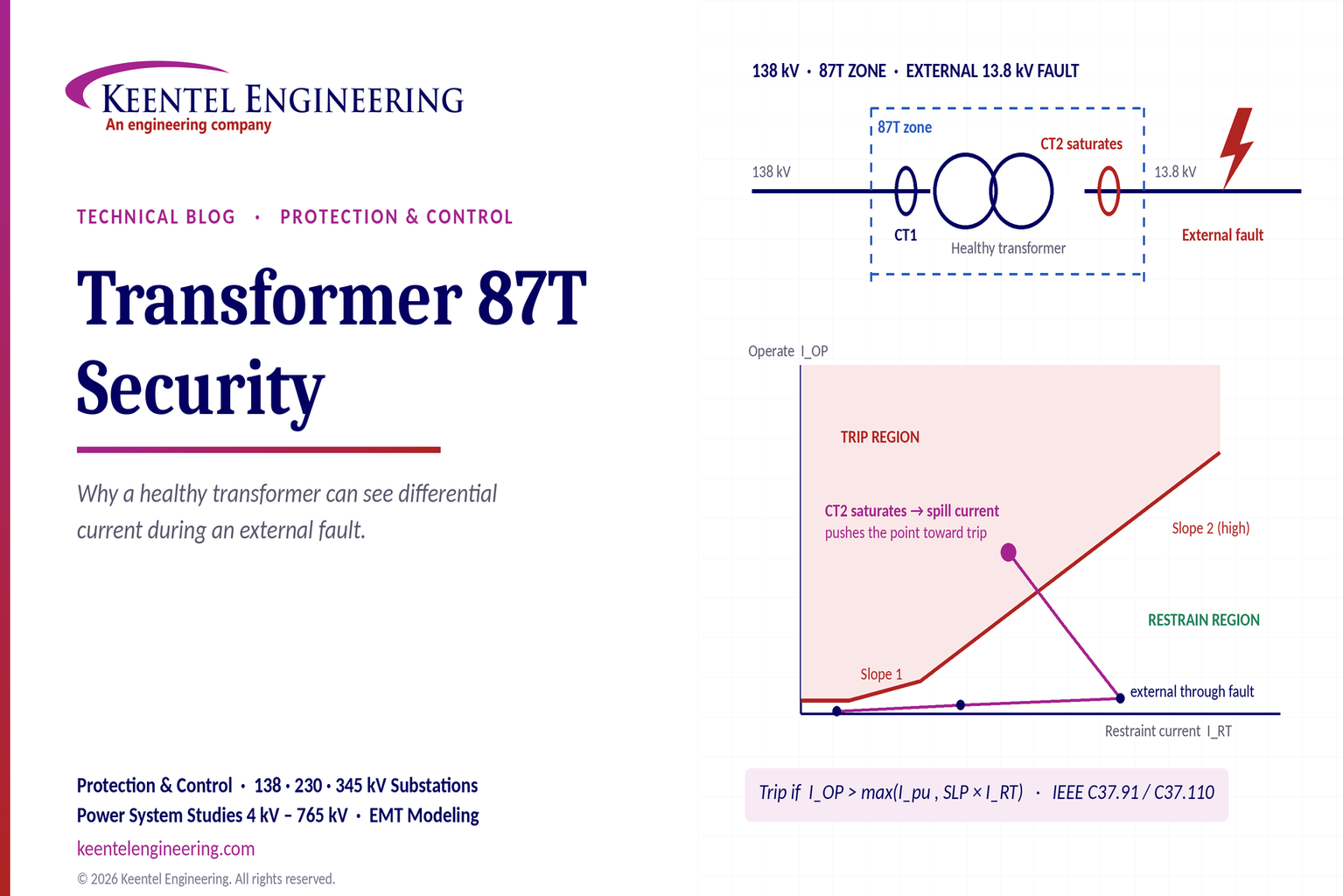
Learn why transformer differential relays detect current during external faults, how CT saturation causes spill current, and how secure 87T protection prevents trips.
By SANDIP R PATEL
•
October 10, 2026
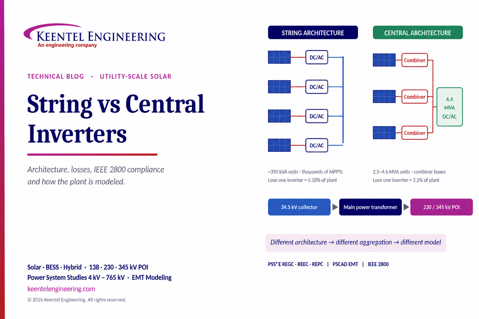
Compare string vs central inverters for utility-scale solar, including efficiency, maintenance, grid compliance, reactive power and interconnection studies.
By SANDIP R PATEL
•
October 9, 2026
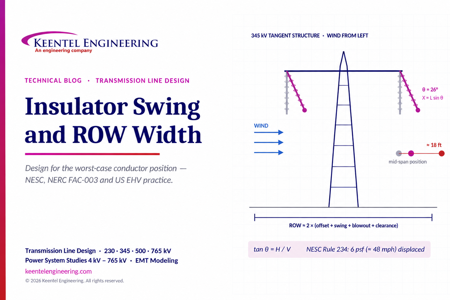
Learn how insulator swing angle and conductor blowout affect transmission line ROW width, with NESC clearances, NERC FAC-003 guidance, and a 345 kV example.
Copy

By SANDIP R PATEL
•
October 3, 2026
Engineering guide to PRC-028 disturbance recording, PRC-029 ride-through and PRC-030 event detection for inverter-based resources.

By SANDIP R PATEL
•
October 3, 2026
A practical guide to SSO classification, SSR, PEDI, Wind-SSCI, EMT analysis, mitigation and protection based on CIGRE TB 909.





