
A Coordinated Electric System Interconnection Review—the utility’s deep-dive on technical and cost impacts of your project.
Challenge: Frequent false tripping using conventional electromechanical relays
Solution: SEL-487E integration with multi-terminal differential protection and dynamic inrush restraint
Result: 90% reduction in false trips, saving over $250,000 in downtime
The three operating regions you have to design to
| Device | Output vs voltage | Response | Best suited to | Main limitations |
|---|---|---|---|---|
| Mechanically switched capacitor or reactor | Proportional to voltage squared | Seconds; discrete steps; limited switching operations per day | Steady-state reactive supply, voltage profile, loss reduction | No dynamic capability; step voltage change on switching; capability collapses when most needed |
| Static var compensator | Capacitive branches proportional to voltage squared | A few cycles; continuously controllable | Continuous control where cost matters and deep voltage support is not the driver | Square-law capability loss; harmonic filters are part of the plant and interact with the network |
| STATCOM | Approximately proportional to voltage — constant current capability | One to two cycles closed loop; converter response faster still | Voltage stability margin, weak interconnections, fast disturbance recovery, flicker and unbalance compensation | Higher capital cost; converter losses; adds a converter and its control dynamics to the network |
| Synchronous condenser | Governed by machine capability and excitation | Excitation response in the hundreds of milliseconds; inherent inertial response instantaneous | System strength and inertia, short-circuit contribution, black start support | Rotating plant with maintenance and losses; slower controlled response than a converter |
| STATCOM with energy storage | Reactive as a STATCOM, plus real power within the storage rating | As STATCOM for reactive; real power limited by storage | Where a real power deficiency is part of the problem | Cost and complexity of the storage; different failure and maintenance profile |
Passing the CAISO IBR Model Review: From the Flat Run to PRC-029 Ride-Through
September 7, 2026 | Blog
A technical guide to the California ISO's August 2026 Dynamic Model Review Guideline for inverter-based resources, the Dynamic Model Validation Procedure and its PSLF toolkit, and the control-mode, frequency-response, voltage-regulation, and ride-through requirements a positive-sequence model must satisfy before it enters a CAISO interconnection study or the WECC base case
Executive Summary
In August 2026 the California ISO, together with the Participating Transmission Owners and the merchant transmission companies in its footprint, issued a revised Dynamic Model Review Guideline for Inverter-Based Interconnection Requests and Operational Resources and a companion Dynamic Model Validation Procedure. Together with a small PSLF EPCL toolkit and a PRC-029 ride-through spreadsheet, these documents define what a positive-sequence model of a solar, wind, storage, or hybrid plant must contain and how it will be tested before it is accepted into a CAISO interconnection study, the Section 10 generator data process, or the WECC base case.
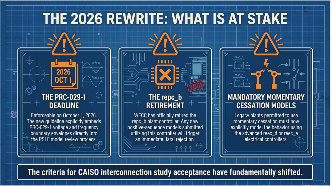
The guideline is not new in concept; it descends from the WECC Inverter-Based Resources Power Plant Modeling and Validation Guideline and has been in place since 2020. What changed in 2026 is consequential. The repc_b plant controller has been retired by WECC and cannot be used in new submissions. The reec_d and reec_e electrical controllers are now required wherever momentary cessation must be modeled, and the new wtgt_b drive-train model is preferred for Type 4 wind. The ride-through section has been rewritten around PRC-029-1, which becomes enforceable on October 1, 2026, and the guideline now states the voltage and frequency envelopes explicitly, requires compliance to be demonstrated at the high-voltage side of the main transformer, and requires the trip settings in the lhvrt and lhfrt protection models to sit outside the must-ride-through zone without touching it.
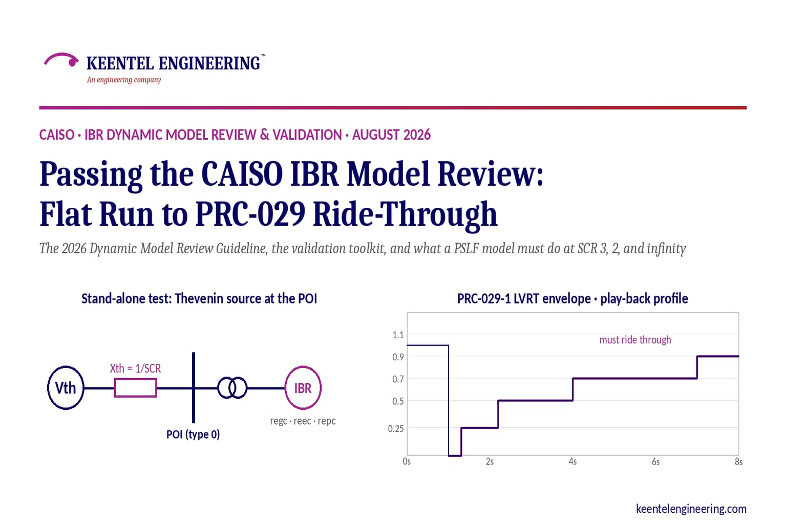
The validation procedure operationalizes the guideline. It places a Thevenin voltage source at the point of interconnection, sets its reactance to produce a chosen short-circuit ratio, and runs six standard simulations: a 20-second flat run with an automated extraction of every control setting; a three-phase fault at the POI at SCR 3 and again at SCR 2; a plant-controller voltage or reactive-power reference step; a frequency reference step; and a play-back of the PRC-029-1 voltage envelope from an infinitely strong source. Each run has pass criteria, and the guideline's Table 1 warns that the older regc_a converter model is not suitable where the SCR is around 2 to 3 or less, which means a plant that submits regc_a will very likely fail the SCR 2 bump test and be asked to move to regc_b.
This guide walks through the guideline section by section — usability, power flow equivalencing, model selection, MVA base scaling, primary frequency response, automatic voltage regulation, and ride-through — then through the toolkit and each test's acceptance criteria. It documents several defects we found in the toolkit itself, and closes with how Keentel Engineering prepares and validates IBR models so they clear the CAISO review the first time, followed by a 25-question FAQ.
Who this guide is for
Developers and owners of solar, wind, battery, and hybrid projects in the CAISO interconnection queue or already operating under the Section 10 generator data process; OEM and EPC modeling teams preparing GE PSLF packages; and consultants who must reconcile plant controller settings with the CAISO, WECC, FERC Order 827 and 842, and PRC-029-1 requirements.
1. Why the CAISO Rewrote Its IBR Model Guidance in 2026
The August 2026 revision is the fourth release of a guideline first issued in October 2020 and updated twice in 2021, when the droop parameters were clarified and "plant V and local V" was added as a valid control mode. The 2026 revision history lists three drivers: new WECC-approved models, the retirement of repc_b, and PRC-029-1 compliance. Behind those three items sit the reliability events that have shaped IBR modeling for a decade — the loss of solar generation in the 2016 Blue Cut fire and subsequent Southern California disturbances, the Odessa events in Texas, and the pattern in every NERC disturbance report that the models used in planning did not predict what the inverters actually did.
The guideline is explicit that mathematically only the converter (REGC) and electrical control (REEC) models are needed to run a simulation, but that the purpose of modeling is to capture how the plant actually behaves. Every model that represents a real control — the plant controller, the wind drive-train and pitch controls, the ride-through protection — is therefore required where the corresponding control exists. A monitored branch must always be defined in the plant controller model, and it must be oriented from the generator toward the grid.
The guideline is co-authored by the CAISO and eight transmission owners: DCR Transmission, GridLiance West, Horizon West Transmission, LS Power Grid California, PG&E, SDG&E, SCE, and Valley Electric Association. That authorship matters. The PTOs run the interconnection studies and the MOD-032 base case processes, so a model that satisfies the guideline is reviewed to the same criteria whether the POI is in the SCE, PG&E, or SDG&E territory, and whether the reviewer is the PTO or the CAISO.
2. Model Usability: The Three Gates Every Submission Must Clear
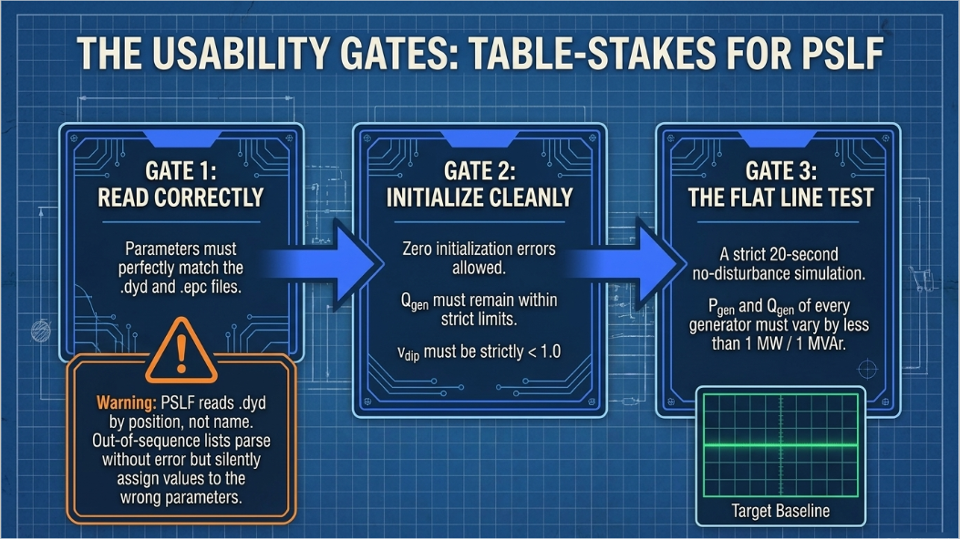
Before anyone looks at control performance, the model must be usable in GE PSLF, the platform the CAISO and its PTOs use for dynamic simulation. The guideline sets three gates.
| Gate | Requirement | How it fails in practice |
|---|---|---|
| 1. Read correctly | The number of buses, lines, transformers, generators, and shunts read from the .epc matches the file; parameters read match the file; the number of dynamic models read from the .dyd matches the file; parameters read match the .dyd. | PSLF reads .dyd parameters by position, not by name. A parameter list entered out of the documented sequence reads without error and silently assigns every value to the wrong parameter. The guideline calls this the most common mistake. |
| 2. Initialize cleanly | No initialization errors; every warning is reviewed and either resolved or explained. | Qgen in the power flow outside the reec Qmax/Qmin on the machine base; Pgen above the governor or plant Pmax; a repc referencing a bus or branch that does not exist; vdip at or above 1.0. |
| 3. Flat line | A 20-second no-disturbance simulation in which Pgen and Qgen of every generator vary by less than 1 MW and 1 MVAr, or less than 1 percent. | Plant controller integrators that wind up because the initialized reference does not match the power flow; a reactive-power set point that fights the voltage regulator; a frequency-response deadband set to zero. |
The 20-second flat-run criterion is stricter than the older 10-second convention used in the CAISO Section 10 acceptance test, and it is checked automatically by the validation toolkit, which also writes a parameter-error report during the same run. A model that passes the flat run has demonstrated only that it is internally consistent; it has not yet demonstrated that it behaves correctly.
3. Building the Power Flow Model: Explicit, Equivalent, and Hybrid
The power flow representation follows the WECC single-generator and multiple-generator equivalents. From the point of interconnection inward, the model must include an explicit interconnection transmission line, explicit representation of every substation (main step-up) transformer, an equivalent collector system, an equivalent pad-mounted transformer with a scaled MVA rating, an equivalent generator scaled to the plant's total capacity, and explicit representation of every plant-level reactive compensation device, modeled as a fixed or switched shunt or, for FACTS devices, as a generator.
Where inverters and pad-mounted transformers are supplied as integrated units and the manufacturer's test data and control inputs are taken at the integrated unit's terminal, the pad-mount is not modeled separately; the equivalent generator represents the integrated unit.
3.1 How many equivalent generators?
The number of equivalents is determined by the number of main substation transformers, the collector systems behind each, and the mix of inverter makes and settings. Each substation transformer is explicit. Identical inverters behind one transformer become one equivalent collector, one equivalent pad-mount, and one equivalent generator. Different inverters with the same control and protection settings may also be combined into one equivalent. Where inverters with different settings sit behind the same transformer, each inverter type with at least 10 MVA installed gets its own equivalent generator and pad-mount; types below 10 MVA may be aggregated with another type.
3.2 Hybrid plants
For AC-coupled hybrids, where each fuel type has its own inverters, each fuel type is modeled explicitly with its own equivalent generator, pad-mount, and collector. The reactive capability requirement applies to the hybrid plant as a whole; an individual fuel type need not meet it alone. For DC-coupled hybrids, where solar and storage share inverters, a single equivalent generator represents the inverters as seen from the AC side, and a negative Pmin on that generator represents the maximum charging power if the battery can charge from the grid.
Design note
The 10 MVA per-inverter-type threshold and the explicit-transformer rule together decide how many equivalent generators a plant has, and therefore whether the plant controller must be repc_c (single generator) or repc_d (multiple generators). Settle this before any dynamic data is entered, because it drives the dispatch scenarios the validation procedure requires.
4. Choosing the Dynamic Models: REGC, REEC, REPC, and the Retirement of REPC_B
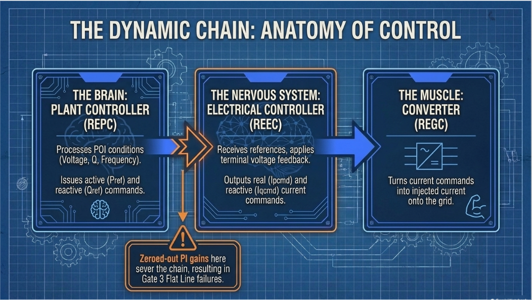
The dynamic model is a chain. The REPC plant controller processes voltage, reactive power, frequency, and active power at the monitored point and issues real (Pref) and reactive (Qref) power references. The REEC electrical controller converts those references, with terminal voltage feedback, into real (Ipcmd) and reactive (Iqcmd) current commands. The REGC generator/converter model turns the current commands into injected current. The lhvrt and lhfrt models trip the plant on defined voltage and frequency conditions. For Type 3 wind, the wtgt, wtga, wtgp, and wtgq models add the drive-train, aerodynamics, pitch, and torque controls that shape the response; for Type 4 wind only the drive-train model applies.
| Function | Model | Applicability in the 2026 guideline |
|---|---|---|
| Converter | regc_a | All IBR, but not suitable for weak-grid POIs where SCR is around 2–3 or less. |
| Converter | regc_b | All IBR; voltage-source interface, numerically robust; suited to weak grids and, properly parameterized, stable down to SCR near 1. CAISO and PTO may require replacement of regc_a with regc_b when numerical issues appear. |
| Electrical control | reec_a | Type 3 and 4 wind, solar PV, DC-coupled BESS that does not charge from the grid. |
| Electrical control | reec_c | Stand-alone BESS; DC-coupled BESS charging from the grid. |
| Electrical control | reec_d | All IBR; enhanced capability over reec_a/b. Required, with reec_e, to model momentary cessation. |
| Electrical control | reec_d | All IBR; enhanced capability over reec_a/b. Required, with reec_e, to model momentary cessation. |
| Plant controller | repc_a | Single generator control, except plant-level power factor control. |
| Plant controller | repc_b | Retired by WECC. Cannot be used in future submissions. |
| Plant controller | repc_c | Single generator; plant-level PF control and coordination of mechanically switched shunts. |
| Plant controller | repc_d | Multiple generators receiving P and Q references from one plant controller; required for hybrids to coordinate and enforce plant-level limits. |
| Ride-through | lhvrt / lhfrt | Voltage and frequency ride-through protection; monitored bus at the actual measurement point, compliance shown at the HV side of the main transformer. |
| Drive-train | wtgt_a / wtgt_b | Type 3; Type 4 when pflag = 1 in reec_a. wtgt_b is preferred for Type 4. |
| Aero, pitch, torque | wtga_a, wtgp_a/b, wtgq_a | Type 3 wind only. |
| Weak-grid supplement | wtgwgo_a | Type 3 and 4 wind at low-SCR connection points; improves post-fault recovery. |
| Fast frequency response | wtgibffr_a | Type 3 and 4 wind inertial-based FFR; must be used with reec_d. |
Three selection rules deserve emphasis. Plant-level power factor control is acceptable only in
coordination with inverter-level voltage regulation, so that the plant as a whole meets the voltage regulation requirement in Section 7. For hybrid interconnection requests, repc_d is mandatory so that the plant-level limits are enforced across the storage and generation equivalents. And any plant that uses or must represent momentary cessation — including legacy plants that are permitted to — must use reec_d or reec_e, because the older reec_a and reec_c cannot represent the blocking logic.
5. MVA Base, Pmax, and the Plant-Level Scaling Rules
The equivalent generator's Pmax in the power flow is the sum of the individual inverter MW outputs needed to achieve the desired MW at the POI, and the guideline notes that individual inverter MW output is often below rated MW because of the common practice of oversizing inverters. The equivalent generator's MVA base is the sum of the individual inverter MVA ratings. Because nearly every dynamic parameter is in per unit on the generator MVA base, the base in the .dyd must equal the base in the .epc; the validation toolkit flags any generator whose power flow Pmax is equal to or greater than its dynamic MVA base as an error.
Two plant-controller models carry their own base rules. In repc_a, the puflag parameter selects whether pbranch and qbranch are on the model MVA base (puflag = 1) or the system 100 MVA base (puflag = 0). The guideline recommends puflag = 1, and the toolkit issues a warning whenever puflag = 0 is found. In repc_d, the plant MVA base MVAplt may be entered as a fixed value, in which case every parameter is on that base, or set to zero, in which case the model computes MVAplt at initialization and at every time step as the sum of the MVA bases of all downstream units whose status is 1.
The repc_d distribution gains Kwi (reactive) and Kzi (active) determine how the plant reference is apportioned among downstream units. For almost every plant they should all be set to 1, which the model interprets as apportionment in proportion to MVA base: two 100 MVA units behind a 200 MVA plant controller asked for 0.1 pu each pick up 10 MW. Where the K values are not all 1, the largest must be normalized to 1 and the others are interpreted as fractions of the largest unit's response, subject to the constraint that the MVA-weighted sum of the K values divided by MVAplt equals 1.
6. Primary Frequency Response: Droop, Deadband, and the Base-Load Flag
IBRs that executed a Generation Interconnection Agreement, or filed an unexecuted one at FERC, on or after May 15, 2018 must provide active-power primary frequency response with 5 percent droop for both under- and over-frequency and a maximum deadband of ±36 mHz, consistent with FERC Order 842. The guideline translates this into power flow and dynamic settings.
In the power flow, the base-load flag on the generator record declares the plant's operating headroom. BL = 0 means Pgen can move up and down, the expected setting for storage and permissible for solar or wind that carries headroom. BL = 1 means Pgen can move down only, the typical and, for planning, the most appropriate setting for solar and wind, which are normally dispatched at maximum available output. BL = 2 means Pgen is fixed and is not compliant with the requirement. The base-load flag governs availability; the dynamic model governs capability.
| Functionality | BL | frqflag | ddn | dup | fdbd1 | fdbd2 |
|---|---|---|---|---|---|---|
| Down regulation only (wind or solar) | 1 | 1 | ≥ 20 on model MVA base | ≥ 20 on model MVA base | [−0.0006, 0) | (0, 0.0006] |
| Up and down regulation (wind, solar, BESS, hybrid) | 0 | 1 | ≥ 20 on model MVA base | ≥ 20 on model MVA base | [−0.0006, 0) | (0, 0.0006] |
The droop constants ddn and dup are in per unit of power per per-unit frequency deviation on the generator nameplate base; 20 corresponds to 5 percent droop. The deadbands fdbd1 (over-frequency) and fdbd2 (under-frequency) are ±0.0006 pu, which is ±36 mHz at 60 Hz. A guideline enhancement distinguishes capability from availability: ddn and dup represent what the inverters can do irrespective of headroom, while the BL flag represents whether headroom exists; when BL = 1 the simulation blocks upward response by setting Pmax equal to Pgen. Plants with agreements before May 15, 2018 have no PFR obligation and should model the field settings as they are.
Check the arithmetic the reviewer will check
The validation procedure's frequency step reduces the reference by 0.3 Hz. With a 36 mHz deadband and 5 percent droop the expected active power change is (0.300 − 0.036) / 60 / 0.05 = 0.088, or about 9 percent of Pmax, which is the figure the procedure quotes. A plant that responds with 5 percent or 15 percent has either the wrong droop base, the wrong deadband, or a ramp limit that is masking the response within the simulation window.
7. Automatic Voltage Regulation: The Seven Control-Mode Combinations
IBRs subject to FERC Order 827 must operate in automatic voltage control mode. In the WECC generic models that behavior is set by three flags in the electrical controller and one in the plant controller. pfflag selects local power factor control (1) or voltage/reactive control (0). vflag selects local voltage control (0) or reactive power control (1). qflag selects constant power factor or reactive power control (0) or voltage control (1). refflag in the plant controller selects plant-level reactive power control (0), plant-level voltage control (1), or plant-level power factor control (2). The guideline's Table 3 lists every valid combination and states that anything else is invalid.
| pfflag | vflag | qflag | refflag | Mode | Compliant |
|---|---|---|---|---|---|
| 0 | N/A | 0 | 0 | Plant Q | No |
| 0 | 1 | 1 | 0 | Plant Q and local Q/V | Yes |
| 0 | N/A | 0 | 1 | Plant V | Yes |
| 0 | 0 | 1 | 1 | Plant V and local V | Yes |
| 0 | 1 | 1 | 1 | Plant V and local Q/V | Yes |
| 0 | N/A | 0 | 2 | Plant PF | No |
| 0 | 1 | 1 | 2 | Plant PF and local Q/V | Yes |
The pattern is simple once seen: voltage regulation must exist somewhere in the chain. Plant-level voltage control (refflag = 1) satisfies it alone. Plant-level reactive power or power factor control satisfies it only if the inverters themselves regulate voltage through the local Q/V loop (vflag = 1, qflag = 1). A plant that holds constant Q or constant PF at the POI with no inverter-level voltage loop is not providing automatic voltage regulation, however precisely it holds its set point. The parameters that coordinate the plant and inverter loops and that reviewers examine are repc vfrz, reec vdip and vup, reec kqv, and the local voltage PI gains kvp and kvi. Existing IBRs not subject to Order 827 model their field settings.
8. Ride-Through: Reactive Current Injection, Momentary Cessation, and PRC-029-1
8.1 The CAISO tariff performance requirements
Projects that executed an interconnection agreement or replaced their inverters on or after April 30, 2019 must meet the CAISO's inverter-based interconnection requirements. Momentary cessation — ceasing to inject current during a fault without mechanical isolation — is prohibited unless the transient high voltage reaches 1.20 pu or more. During transient low voltage the inverters must inject reactive current in direct proportion to the per-unit voltage decrease at the inverter terminals, reaching full rated reactive current when the terminal voltage falls to 0.50 pu. Between 1.10 and 1.20 pu the plant must continue to operate and absorb reactive current. When voltage returns to the 0.90–1.10 pu normal band the inverters must return to active current injection at a ramp of at least 100 percent per second, completing the transition within one second; return from any permitted momentary cessation above 1.20 pu must also complete within one second. Active power reaching 95 percent of its pre-fault value is the guideline's definition of return to normal, and the regc rrpwr parameter must therefore be no less than 1.0 pu/s.
8.2 How the requirements map to reec parameters
The reactive current limit must be non-zero throughout the transient low-voltage region and at least 1.0 pu below 0.5 pu voltage. With pqflag = 0 (Q priority), the reactive current limit must be at least 2 × (1.0 − V) for voltages between 0.5 and 1.0 pu and at least 1.0 pu below 0.5 pu; if the VDL1 table is used to shape the limit, its points must lie on or above that line. Plants that operate in P priority under normal and high-voltage conditions and switch to Q priority under low voltage may still be modeled with pqflag = 0, because priority only matters when the total current demand exceeds the inverter limit, which normally happens only under low voltage. Where P priority must be retained, the guideline shows how to achieve the same effective Q injection with pqflag = 1 by shaping the VDL2 table so that Ip is limited to zero at 0.5 pu, 0.8 at 0.7 pu, 0.98 at 0.9 pu, and 1.0 at 1.0 pu; because the effective Q limit is then the square root of Imax² minus Ip², the resulting Iqmax reproduces the Q-priority curve.
The quantity of reactive current injected can be set either through the voltage-dip logic — vdip between 0 and 1.0, typically 0.9, with kqv ≥ 2 — or, with the dip logic disabled, through the local voltage loop with qflag = 1 and kvp ≥ 2. For transient high voltage, vup = 1.1 with a non-zero kqv gives a non-zero reactive current limit in the right direction between 1.1 and 1.2 pu.
Legacy projects that executed agreements before April 29, 2019 and that use momentary cessation must model it truthfully with reec_d or reec_e, and the guideline recommends the blocking thresholds be as favorable as the equipment allows: vblkl as low as possible and no higher than 0.9, vblkh as high as possible and no lower than 1.1, and tblk_delay as small as possible.
8.3 PRC-029-1
PRC-029-1 takes effect
on October 1, 2026 and applies to Bulk Electric System IBRs and to non-BES IBRs that have or contribute to an aggregate nameplate of 20 MVA or more connected through a system designed to deliver that capacity to a common point at 60 kV or above. Consistent with FERC Order 901, a limited, documented exemption is available for legacy IBRs whose hardware must be physically replaced and cannot be reconfigured by software; all future IBRs must comply. The guideline reproduces the ride-through envelopes and, for the first time, embeds them into the model review.
| Voltage at the HV side of the main transformer (pu) | Region | AC-connected Type 3/4 wind (s) | All other IBR, including via VSC-HVDC (s) |
|---|---|---|---|
| > 1.20 | May ride through | N/A | N/A |
| ≥ 1.10 | Mandatory | 1.0 | 1.0 |
| > 1.05 | Continuous | 1800 | 1800 |
| 0.90 – 1.05 | Continuous | Continuous | Continuous |
| < 0.90 | Mandatory | 3.0 | 6.0 |
| < 0.70 | Mandatory | 2.5 | 3.5 |
| < 0.50 | Mandatory | 1.2 | 1.2 |
| < 0.25 | Mandatory | 0.16 | 0.32 |
| < 0.10 | Permissive | 0.16 | 0.32 |
| System frequency (Hz) | Minimum ride-through (s) |
|---|---|
| > 61.8 | May trip |
| > 61.2 | 299 |
| 58.8 – 61.2 | Continuous |
| < 58.8 | 299 |
| < 57.0 | May trip |
Three modeling consequences follow. First, the monitored bus in the lhvrt and lhfrt records must reflect the actual measurement point, but compliance is demonstrated at the high-voltage side of the main transformer; the guideline shows the record with the generator terminal as the model bus and the 230 kV bus as the monitored bus. Second, the trip thresholds dvtrp and dftrp and their timers dttrp must lie outside the must-ride-through zone and must not coincide with or touch the envelope — a trip point of 1.10 pu at 1.0 s is not acceptable because it sits on the boundary. Third, the per-unit voltage base is the nominal transmission voltage unless the PC, TP, or TO specifies otherwise, so a plant monitored at a 500 kV bus on a 525 kV nominal system uses vref = 1.05 in the lhvrt record and a play-back profile scaled by 1.05.
In the permissive region below 0.10 pu the IBR may either continue injecting current or enter current blocking, but it must resume injection within 5 cycles of the
voltage returning to the mandatory or continuous region.
9. The Validation Toolkit: Thevenin Source, SCR Sweep, and Six Standard Runs
The CAISO validation procedure tests a plant model in isolation before it is placed in the WECC full-loop case. The plant's power flow is modified so that the POI bus becomes the swing bus (type 0) and an infinite generator is attached to it. In dynamics that generator carries a gthev Thevenin-source model whose MVA base is set by a pre-run EPCL to the sum of the MVA bases of every in-service plant generator and whose reactance xth is set to the reciprocal of the desired short-circuit ratio. With xth = 0.33 the POI has an SCR of about 3 on the plant's MVA base; xth = 0.5 gives SCR 2; xth = 0.0001 gives an effectively infinite source for the play-back test. The package ships pre-run files for SCR 1, 2, 2.5, 3, 4, 5, 10, and 1000.
The pre-run EPCL also rebases the repc_b plant limits (for legacy plants that still carry that model) so that the reference change tests apply to the plant's dispatched point rather than its nameplate. The main program, IBR_model_test_v2.p, is a DYTOOLS-style stability processor that reads a runs file, loads the .sav and the Thevenin and plant .dyd files, runs the pre-run EPCL, initializes, applies either a disturbance EPCL or a play-back CSV, runs to the end time, and stores channels. It runs in both PSLF Classic and the Advanced UI, and the runs file name is hard-coded.
| Run | Pre-run (SCR) | Disturbance | Post-run | Purpose |
|---|---|---|---|---|
| 1. Flat run | prerun_flat.p (SCR 3) | Flat.p — no disturbance, 40 s | CheckREModels_v2.p | Usability gate 3; automated extraction of control modes and suspicious parameters to controlmode.csv and parametererrors.csv |
| 2. Bump at SCR 3 | prerun_setGThev3.p | Bump.p — 3-phase fault at POI, cleared after 4 cycles (>200 kV) or 6 cycles (<200 kV) | none | Large-disturbance stability, reactive current injection, active power recovery |
| 3. Bump at SCR 2 | prerun_setGThev2.p | Bump.p | none | Weak-grid robustness; regc_a models typically fail here |
| 4. Voltage reference step | prerun_setGThev3.p | vstep_d.p — PPC Vref −0.025 pu at 5 s, +0.05 pu at 35 s, run to 65 s (qstep variant for Q-control plants: −0.05/+0.10 pu) | none | Small-disturbance response of the plant voltage/reactive loop |
| 5. Frequency reference step | prerun_setGThev3.p | fstep_d.p — frequency reference −0.3 Hz at 5 s, +0.6 Hz at 35 s | none | Primary frequency response; only where frqflg = 1 |
| 6. Voltage ride-through play-back | prerun_setGThev0.p (SCR ~1000) | play_vrt_other_ibr.csv or play_vrt_wind.csv (500 kV variants ×1.05) through TheveninPB.dyd | none | Ride-through of the PRC-029-1 low- and high-voltage envelope |
The runs file also fixes the simulation parameters: a quarter-cycle time step of 0.0041667 s, a 40-second end time, plot intervals of one step throughout, the bad-data fix flag on, and the model-status check on. Every run uses the same .sav and plant .dyd; only the Thevenin file, the pre-run, and the disturbance change.
9.1 Dispatch scenarios
The procedure requires the plant to be tested at more than one dispatch where the technology warrants it. Wind and solar are dispatched slightly below Pmax, leaving about 10 percent headroom so the frequency step can show upward response. A stand-alone BESS is tested near Pmax, near Pmin (charging), and at Pgen = 0 to prove voltage and frequency control at zero active power. A hybrid is tested with the BESS discharging and other generators off, the BESS charging (if grid-charging is allowed) and others off, the BESS off and others on, the BESS discharging with others on at a net MW below the plant limit, and the BESS charging with others on at net zero, to prove the coordination the repc_d model is supposed to provide. Each dispatch is a separate .sav and a separate set of runs.
9.2 The play-back profiles
The ride-through test does not simulate a fault; it plays a voltage waveform into the infinite source so that the POI voltage follows the PRC-029-1 envelope exactly. The "other IBR" profile holds 1.0 pu for one second, drops to zero for 0.32 s, steps to 0.25 pu until 2.2 s, 0.5 pu until 4 s, 0.7 pu until 7 s, 0.9 pu until 20 s, returns to 1.0 pu, then at 30 s steps to 1.2 pu for one second, drops to 1.1 pu, and holds to 40 s. The wind profile is the same shape with the shorter wind durations: zero for 0.16 s, 0.25 pu until 2.2 s, 0.5 pu until 3.5 s, and 0.7 pu until 4 s. The 500 kV variants multiply every voltage by 1.05. The plant passes if it remains connected and continues to produce active and reactive output through the entire profile.
The frequency ride-through is not simulated. The lhfrt settings are instead checked against the PRC-029-1 frequency envelope in the companion spreadsheet, which also carries LVRT and HVRT sheets for wind and for all other IBR: the reviewer pastes the interconnection customer's dvtrp, dttrp, dftrp, and vref values from the .dyd and the sheet plots them against the envelope.
10. Reading the Results: What Reviewers Look For in Each Test
| Test | What the reviewer examines | Typical failure |
|---|---|---|
| Flat run | Log and event file show no errors and no events; terminal voltage, P, and Q flat with spread below 1 MW/MVAr or 1 percent; values match the power flow. parametererrors.csv is empty or explained. controlmode.csv shows a compliant mode and non-zero gains where the mode requires them. Regulated bus and monitored branch noted; branch direction generator-to-grid. | Slow drift from integrator wind-up; Q spread from a set point mismatch; "voltage control gains are zero" note against a mode that depends on them; "no PPC model" for a plant that has one. |
| Bump (SCR 3, then 2) | ipcmd and iqcmd from the regc model: neither should go to zero unless momentary cessation is permitted; iqcmd should move in the direction that supports voltage and reach iqmax during the fault. Post-fault terminal voltage overshoot and settling time. With multiple units, all Qgen on one plot to see coordination. Active power recovery time to pre-fault level. | ipcmd collapses to zero (unintended cessation); iqcmd saturates at the wrong sign; sustained oscillation at SCR 2 with regc_a; P recovery slower than 1 pu/s because rrpwr < 1; units fighting each other in a hybrid. |
| Voltage / Q reference step | iqcmd ramps up on the increased reference and down on the decreased one; the controlled voltage or Q reaches the new reference; time to reach it; quality of regulation. | Reference never reached (kp, ki too small or emax/emin clamping); overshoot and ringing (gains too high, vfrz interfering); no response because refflag points to a bus that is not the intended regulated bus. |
| Frequency reference step | iqcmd (and P) ramp down on the +0.3 Hz reduction of reference and up on the subsequent +0.6 Hz; magnitude about 9 percent of Pmax for 5 percent droop and 36 mHz deadband; time to reach droop response. | No upward response because BL = 1 or Pgen = Pmax; response half or double the expected value from a base or deadband error; response masked by a ramp-rate limit. |
| Voltage ride-through play-back | Plant stays connected through the entire 40-second profile including the 1.2 pu excursion; P and Q output continue; lhvrt does not operate. | Trip at 0.25 pu because dttrp is set inside the 1.2 s step; trip during the 1.2 pu second; momentary cessation below 1.2 pu on a post-2019 plant. |
| PRC-029 spreadsheet | dvtrp/dttrp and dftrp/dttrp plotted against the envelope lie outside it and do not touch it; vref 1.05 where the monitored bus is 500 kV. | Trip point exactly on the envelope corner (e.g., 1.10 pu at 1.0 s); frequency trip at 61.2 Hz with 299 s timer; wrong vref at 500 kV. |
The automated settings extractor deserves a closer look because it is the first thing a CAISO or PTO reviewer opens. For every generator it records Pmax and MVA base, the P/Q priority flag, the derived control mode string (constant power factor, constant Q, plant-level Q, plant-level V, plant-level PF, local V, plant-level Q and local Q/V, and so on), every flag and gain in the reec and repc, the base-load flag, the frequency-response parameters, the regc low-voltage power logic parameters (lvplsw, brkpt, zerox), rrpwr, the plant Pmax and Pmin, and the repc_d distribution gains. It appends notes where voltage or Q gains are zero, where rrpwr is below 1, and where no plant controller exists. In a separate file it lists parameter checks: MVA base not above Pmax; regc accel outside 0.7–1.0; reec Qmax or Qmin on the machine base narrower than the power flow limits; trv = 0; vdip ≥ 1 or vup ≤ 1; repc emax below 0.05 or emin above −0.05; a zero deadband; puflag = 0; a repc Pmax more than 5 MW from the power flow Pmax; and, for repc_b plants, a suspicious 100 MW limit and droop constants below 5 percent on the plant Pmax base.
11. Defects and Ambiguities We Found in the Toolkit
Keentel ran the published EPCL through a line-by-line review. The toolkit is fit for purpose, but a submitter who relies on it uncritically should know the following.
| Item | Observation | Consequence |
|---|---|---|
| reec_d vup check | In the settings extractor's reec_d block, the vup sanity check reads the vup parameter from the reec_b record at the same model index rather than from reec_d. | For a plant with reec_d, the "vup should be above 1.0" check is evaluated against unrelated data or a default and may pass or fail spuriously. Verify vup manually for reec_d plants. |
| SCR 2.5 pre-run file name | The procedure's SCR table names the SCR 2.5 pre-run "prerun_setGThev2+.p", but the distributed file carrying xth = 0.4 is named prerun_setGThev2.p, colliding with the SCR 2 file. | Copying the package into one folder overwrites one of the two. Confirm which xth is in the file before running the SCR 2 bump. |
| Generator loop bound | Every pre-run EPCL loops "for @i = 0 to casepar[0].ngen" when summing MVA base; the valid index range ends at ngen − 1. | One iteration past the last generator. Harmless on most cases but can add a stale or zero record to the Thevenin MVA base on some. |
| Uninitialized accumulators | The repc_b rebasing block accumulates @pgen and @qgen without first setting them to zero. | EPCL numeric variables default to zero at program start, so this works once per invocation, but it is fragile if the block is reused. |
| SCR definition | SCR is set as 1/xth on the sum of the plant generators' MVA bases at the POI bus, with no plant impedance between the source and the equivalent generators' step-up. | This is stricter than an SCR computed on plant Pmax or at the inverter terminals. A plant marginal at "SCR 3" in an interconnection study may see a lower effective SCR in this test. |
| Retired repc_b still checked | The extractor and pre-runs still carry repc_b logic even though the guideline retires the model. | Legacy support only; a new submission that relies on repc_b will be rejected on model selection regardless of test results. |
| Compliance is not flagged automatically | controlmode.csv reports the derived control mode but does not mark "Plant Q" or "Plant PF" as non-compliant. | The reviewer compares the reported mode to the guideline's Table 3 by hand; submitters should do the same before submitting. |
| Flat-run duration | The guideline requires a 20-second flat run; the runs file uses a 40-second end time for all runs, including the flat run. | Conservative, not conflicting: a model that is flat for 40 seconds is flat for 20. |
12. How Keentel Engineering Gets IBR Models Through Review
Keentel Engineering prepares, validates, and defends positive-sequence and EMT models for utility-scale solar, wind, storage, and hybrid plants in the CAISO footprint and across the Western Interconnection, and delivers studies on PSLF, PSS®E, PSCAD/EMTDC, DIgSILENT PowerFactory, ASPEN OneLiner, and ETAP across 4 kV to 765 kV. Our objective on a CAISO model submission is a package that passes the six standard runs at the first review.
| Service | What Keentel delivers |
|---|---|
| Power flow equivalencing | Plant topology reduced to the WECC single- or multiple-generator equivalent per Section 3: explicit main transformers, one equivalent per inverter type ≥ 10 MVA, scaled pad-mount ratings, collector equivalent, explicit plant reactive devices; hybrid AC- and DC-coupled representations with correct Pmin for charging; Pmax and MVA base derived from inverter data. |
| Dynamic model assembly | regc_b / reec_d or reec_e / repc_c or repc_d model chains built from OEM parameter sets and plant controller settings; conversion from PSS®E or PowerFactory OEM models; lhvrt and lhfrt records with the correct monitored bus and vref; Type 3 and 4 wind model chains including wtgt_b and, where warranted, wtgwgo_a. |
| Requirement mapping | Control-mode selection against the guideline's Table 3; PFR settings per Table 2 with the correct BL flag by technology; reactive-current injection settings (pqflag, VDL tables, vdip/kqv or qflag/kvp, vup); rrpwr ≥ 1; PRC-029-1 trip settings placed outside the envelope with documented margin; legacy momentary-cessation representation where permitted. |
| Pre-submission validation | The full CAISO test package run in PSLF at SCR 3, 2, and infinite source, plus additional SCR points where the interconnection study indicates a weak grid; all required dispatch scenarios for BESS and hybrids; controlmode.csv and parametererrors.csv reviewed and cleared; a results report with the plots reviewers expect (ipcmd/iqcmd, terminal voltage, P and Q, plant-level coordination). |
| EMT and benchmarking | PSCAD model assembly per the CAISO EMT Modeling Requirements; positive-sequence versus EMT benchmarking of the bump, step, and ride-through tests; sub-synchronous and control-interaction screening for weak POIs. |
| Review response | Technical responses to CAISO and PTO review comments within the interconnection or Section 10 timelines; model retuning; coordination with the OEM where a parameter change requires a firmware or settings confirmation. |
| Operational resources | Re-validation of existing plants under the Section 10 five- and ten-year cycles, after repowering or inverter replacement, and for PRC-029-1 readiness ahead of the October 1, 2026 effective date; MOD-026/027 test-report interpretation into model parameters. |
Keentel specifies and interprets field tests; the tests themselves are performed by accredited testing contractors. Some analysis platforms and work scopes may be carried by Keentel's subconsultants under Keentel's direction. To discuss a model submission, contact Keentel Engineering at (813) 389-7871 or contact@keentelengineering.com, or schedule a 15-minute call at calendly.com/keentel-engineering/15min.
References and Further Reading
Primary sources are listed first. Links were current at publication in September 2026.
CAISO
- California ISO et al., Dynamic Model Review Guideline for Inverter Based Interconnection Requests and Operational Resources, white paper, August 2026 (revision history 10/15/2020, 5/18/2021, 6/2/2021, 8/6/2026).
- California ISO, CAISO Dynamic Model Validation Procedure for Inverter-Based Resources (CAISO/TIP/RT), with the accompanying PSLF EPCL test package (IBR_model_test_v2.p, CheckREModels_v2.p, prerun_setGThevn.p, Runs_IBR_Tests.runs) and the PRC-029 Ride-Through Requirements spreadsheet.
- California ISO, Electromagnetic Transient Modeling Requirements, April 2021; Business Practice Manual for Transmission Planning Process, Section 10.
- CAISO tariff filings: FERC Order 827 compliance (ER17-114, October 2016); automatic voltage regulator requirements (ER17-490, December 2016); inverter-based interconnection requirements including momentary cessation and transient data recording (ER19-1153, accepted July 2019).
WECC and NERC
- WECC Modeling and Validation Work Group, Inverter-Based Resources Power Plant Modeling and Validation Guideline, 2026; WECC Approved Dynamic Models, May 2026; WECC memoranda on RES modeling updates (February 2023 Rev 27b; January 2024).
- NERC, PRC-029-1 Frequency and Voltage Ride-through Requirements for Inverter-based Resources, effective October 1, 2026; Project 2020-02 implementation plan for PRC-024-4 and PRC-029-1.
- NERC Inverter-Based Resource Performance Subcommittee, Reliability Guideline: Power Plant Model Verification for Inverter-Based Resources, September 2018; Reliability Guideline: Performance, Modeling, and Simulations of BPS-Connected Battery Energy Storage Systems and Hybrid Power Plants, June 2023.
FERC
- FERC Order No. 827 (reactive power requirements for non-synchronous generation, 2016); Order No. 842 (primary frequency response, 2018); Order No. 901 (reliability standards for inverter-based resources, October 2023).
Frequently Asked Questions
1. What does the CAISO IBR Dynamic Model Review Guideline apply to?
Inverter-based interconnection requests and operational inverter-based resources in the CAISO footprint: Type 3 and Type 4 wind, solar PV, battery storage, and hybrids. It is co-authored by the CAISO and eight transmission owners, so the same criteria apply in every PTO territory and in the CAISO's own review.
2. What changed in the August 2026 revision?
Three things: new WECC-approved models were added (reec_e, wtgt_b, wtgp_b, wtgwgo_a, wtgibffr_a); the repc_b plant controller was retired and cannot be used in future submissions; and the ride-through section was rewritten around PRC-029-1, including the voltage and frequency envelopes, the requirement to demonstrate compliance at the high-voltage side of the main transformer, and the rule that lhvrt/lhfrt trip settings must not touch the envelope.
3. What is the flat-run criterion?
A 20-second no-disturbance simulation in which each generator's Pgen and Qgen vary by less than 1 MW and 1 MVAr, or less than 1 percent, with no initialization errors and every warning explained. The validation toolkit runs it for 40 seconds and extracts every control setting at the same time.
4. Which converter model should I use?
regc_b. The guideline states that regc_a is not suitable where the POI short-circuit ratio is around 2 to 3 or less, and the standard test package includes a bump test at SCR 2. regc_b uses a voltage-source interface, is numerically robust, and when properly parameterized runs down to SCR near 1. The CAISO and PTOs may require replacement of regc_a where numerical issues appear.
5. Which electrical control model should I use?
reec_a remains valid for wind, solar, and DC-coupled storage that does not charge from the grid; reec_c for stand-alone or grid-charging storage. reec_d and reec_e are valid for any IBR and are required if any enhanced feature, including momentary cessation, must be represented. reec_e adds local PI control of Q or PF, local PI control of P, and a P/Q priority flag active during faults.
6. Which plant controller should I use?
repc_a or repc_c for a single equivalent generator (repc_c where plant-level PF control or coordination of mechanically switched shunts is needed), and repc_d whenever more than one equivalent generator receives references from one plant controller, which is mandatory for hybrid interconnection requests. repc_b is retired.
7. How many equivalent generators does my plant need?
One per main substation transformer at minimum; behind each transformer, one per inverter type with different control or protection settings that has at least 10 MVA installed. Identical inverters, or different inverters with identical settings, combine into one equivalent. AC-coupled hybrids need one per fuel type; DC-coupled hybrids use one hybrid generator with a negative Pmin for charging.
8. How are Pmax and MVA base set?
Pmax of the equivalent is the sum of individual inverter MW outputs needed for the desired POI MW, which is often below the sum of rated MW because inverters are oversized. MVA base is the sum of inverter MVA ratings. The .dyd MVA base must equal the .epc MVA base; the toolkit flags any generator whose Pmax is equal to or greater than its dynamic MVA base.
9. What is the primary frequency response requirement?
For IBRs with a GIA executed or filed on or after May 15, 2018: 5 percent droop for under- and over-frequency with a maximum deadband of ±36 mHz. In the model: frqflag = 1, ddn and dup at or above 20 on the model MVA base, fdbd1 in [−0.0006, 0) and fdbd2 in (0, 0.0006], with BL = 1 for solar and wind (down only) or BL = 0 for storage and hybrids (up and down). BL = 2 is non-compliant.
10. What is the difference between capability and availability in frequency response?
ddn and dup describe what the inverters can do; the base-load flag describes whether operating headroom exists. With BL = 1 the simulation sets Pmax equal to Pgen so upward response is blocked even though the droop is present. For the frequency step test to show upward response, Pgen must be dispatched below Pmax and BL must be 0.
11. Which voltage control modes are compliant?
Plant V alone; Plant V with local V; Plant V with local Q/V; Plant Q with local Q/V; and Plant PF with local Q/V. Plant Q alone and Plant PF alone are not compliant because no element in the chain regulates voltage. Any combination not in the guideline's Table 3 is invalid.
12. Can my plant run in power factor control at the POI?
Only in coordination with inverter-level voltage regulation (vflag = 1, qflag = 1 in the reec, refflag = 2 in repc_c or repc_d), so that the plant still meets the automatic voltage regulation requirement of FERC Order 827.
13. Is momentary cessation allowed?
For projects that executed an interconnection agreement or replaced inverters on or after April 30, 2019, no, except when transient voltage reaches 1.20 pu or more, and return must complete within one second. Legacy projects that use it must model it with reec_d or reec_e, with vblkl no higher than 0.9, vblkh no lower than 1.1, and the smallest achievable tblk_delay.
14. How much reactive current must be injected during a fault?
Reactive current proportional to the per-unit voltage decrease at the inverter terminals, reaching full rated reactive current at 0.50 pu. In the model the reactive current limit must be at least 2 × (1 − V) between 0.5 and 1.0 pu and at least 1.0 pu below 0.5 pu, achieved with pqflag = 0 or with pqflag = 1 and a shaped VDL2 table; the injection itself via vdip about 0.9 with kqv ≥ 2, or qflag = 1 with kvp ≥ 2.
15. How fast must active power recover?
At a ramp of at least 100 percent per second once voltage returns to the 0.90–1.10 pu band, completing within one second, with 95 percent of pre-fault active power counted as recovery. The regc rrpwr parameter must therefore be at least 1.0 pu/s; the toolkit notes any generator with rrpwr below 1.
16. What are the PRC-029-1 voltage ride-through times?
For all IBR other than AC-connected wind: 1.0 s at or above 1.10 pu, 1800 s above 1.05 pu, continuous from 0.90 to 1.05, 6.0 s below 0.90, 3.5 s below 0.70, 1.2 s below 0.50, and 0.32 s below 0.25 and in the permissive region below 0.10. AC-connected Type 3 and 4 wind: 3.0, 2.5, 1.2, and 0.16 s for the low-voltage steps. Above 1.20 pu the IBR may ride through. Frequency: 299 s above 61.2 Hz and below 58.8 Hz; may trip above 61.8 or below 57.0.
17. Where is PRC-029-1 compliance measured?
At the high-voltage side of the main transformer, even if the plant's protection measures elsewhere. The lhvrt and lhfrt records should name the actual measurement bus as the monitored bus, and the trip settings must produce compliance at the HV bus. For a 500 kV monitored bus on a 525 kV nominal system, vref is 1.05.
18. How far outside the envelope must trip settings be?
The guideline says the settings must be outside the must-ride-through zone and must not coincide with or touch the envelope. It does not prescribe a margin. Keentel documents a specific margin for each point, typically in the order of the measurement and relay timing uncertainty, and shows it on the spreadsheet plot.
19. How does the validation toolkit set the SCR?
A gthev Thevenin source is attached to the POI bus (made type 0). A pre-run EPCL sets its MVA base to the sum of the plant generators' MVA bases and its reactance xth to 1/SCR: 0.33 for SCR 3, 0.5 for SCR 2, 0.4 for SCR 2.5, 0.0001 for the effectively infinite source used in the play-back test. Files are provided for SCR 1, 2, 2.5, 3, 4, 5, 10, and 1000.
20. What are the six standard runs?
Flat run with settings extraction at SCR 3; three-phase POI fault (4 cycles above 200 kV, 6 below) at SCR 3; the same fault at SCR 2; plant controller voltage (or Q) reference step at SCR 3; frequency reference step at SCR 3; and voltage ride-through play-back of the PRC-029-1 envelope from an infinite source. Storage and hybrids repeat the set at several dispatches.
21. What should the frequency step show?
With the reference reduced by 0.3 Hz and a 36 mHz deadband, a 5 percent droop plant should change active power by about (0.3 − 0.036)/60/0.05, or roughly 9 percent of Pmax, then reverse on the +0.6 Hz step. The test is only run where frqflg = 1, and upward response requires headroom and BL = 0.
22. Is the frequency ride-through simulated?
No. The procedure states the test is not needed; lhfrt settings are checked against the PRC-029-1 frequency envelope in the companion spreadsheet.
23. What happens after the stand-alone test?
The model is placed in the WECC full-loop case and the PTO performs its usual bump test there. The stand-alone package is what changed in 2026; the full-loop practice is unchanged.
24. Are there errors in the published toolkit?
A few. The settings extractor's reec_d block reads vup from the reec_b record; two pre-run files share the name prerun_setGThev2.p (SCR 2 and SCR 2.5); the pre-run loops overrun the generator array by one; and the extractor reports control mode without flagging the non-compliant modes. None prevents use, but each is worth knowing before relying on the outputs.
25. How does Keentel help?
Keentel builds the equivalent power flow and the regc/reec/repc/lhvrt model chain to the guideline, maps every tariff, Order 827/842, and PRC-029-1 requirement to a parameter, runs the complete CAISO test package at multiple SCRs and dispatches before submission, produces the reviewer-ready plots and CSVs, benchmarks against PSCAD where the POI is weak, and answers CAISO and PTO review comments. Contact (813) 389-7871 or contact@keentelengineering.com.
Disclaimer
This document is published by Keentel Engineering for general technical information and educational purposes. It summarizes publicly posted California ISO, WECC, NERC, and FERC materials as they stood in September 2026. Those documents, the CAISO Tariff and Business Practice Manuals, and the NERC Reliability Standards control over any summary here and are revised periodically. Readers must verify every requirement, parameter range, and date against the current controlling document before relying on it.
Nothing in this document constitutes a compliance determination, legal advice, or engineering services for any specific facility. Model acceptance is determined by the CAISO and the applicable Participating Transmission Owner; PRC-029-1 compliance is determined by the Compliance Enforcement Authority. Parameter values quoted are the guideline's requirements and examples, not recommendations for any particular plant.
The observations on the CAISO EPCL toolkit are Keentel's own reading of the published code and are offered to assist users; they have not been confirmed by the CAISO.
Keentel Engineering provides electrical engineering and NERC Operations and Planning compliance support services. Field testing of generating units is performed by accredited testing contractors. Some analysis platforms and work scopes may be carried by Keentel's subconsultants under Keentel's direction; Keentel does not share its study methodologies, workflows, or tool configurations.
Keentel Engineering is not affiliated with, endorsed by, or sponsored by the California Independent System Operator, any of the transmission owners named, the Western Electricity Coordinating Council, the North American Electric Reliability Corporation, the Federal Energy Regulatory Commission, or any software vendor. GE PSLF, PSS®E, PSCAD, DIgSILENT PowerFactory, ASPEN OneLiner, and ETAP are trademarks of their respective owners and are named for identification only; Keentel adopts no vendor performance claim.
Keentel Engineering makes no warranty, express or implied, as to the accuracy, completeness, or fitness for any purpose of the information in this document, and accepts no liability for any loss arising from its use.
State of Florida — Registry No. 36853, KEENTEL LLC, DBA: KEENTEL ENGINEERING. Copyright 1995–2026 Keentel Engineering. All Rights Reserved. This document is original work of Keentel Engineering and may not be reproduced, distributed, or adapted without written permission, except for brief quotation with attribution.
| Head Office — Tampa | Austin | Sacramento | Baltimore |
|---|---|---|---|
| 400 N Ashley Dr STE #2600 | 5900 Balcones Drive STE 100 | 1401 21st St Ste R | 306 W Redwood St STE 200 |
| Tampa, FL 33602 | Austin, TX 78731 | Sacramento, CA 95811 | Baltimore, MD 21201 |
| (813) 389-7871 | (512) 591-0752 | (916) 913-4524 | (410) 225-2181 |

About the Author:
Sandip "Sonny" R. Patel, P.E.
IEEE Senior Member · Founder & CEO, Keentel Engineering
In 1995, Sonny Patel earned his Electrical Engineering degree from the University of Illinois. But degrees don't build legacies — action does.
For three decades, he has worked the power industry from every side of the table: 16 years as a utility engineer at Exelon/Commonwealth Edison; generation leadership across hydroelectric, industrial steam turbine, and a 9 GW renewable fleet; NERC Regional Entity Senior Compliance Engineer and Audit Team Lead, auditing some of the nation's largest utilities; and testing and commissioning lead on equipment up to 765 kV — the very top of the North American grid.Utility. Generator. Regulator. Consultant. Few engineers have seen all four seats. Fewer still have sat in them.
His experience spans nuclear, hydro, conventional generation, renewables, oil and gas, mining — and today's data centers, where he is authoring a three-book series on data center design. He is a Licensed Professional Engineer in six states and a Licensed Electrical Contractor in Florida (Unlimited EC) — he doesn't just design the work; he's qualified to stand behind its execution.Today, as Founder and CEO of Keentel Engineering, Sonny leads a nationwide team of engineers delivering substation design, power system studies, NERC compliance, and commissioning — done right, coast to coast.Three decades. Every side of the table. One standard: accountable engineering.
Services

Let's Discuss Your Project
Let's book a call to discuss your electrical engineering project that we can help you with.
About the Author:
Sandip "Sonny" R. Patel, P.E.
IEEE Senior Member · Founder & CEO, Keentel Engineering
In 1995, Sonny Patel earned his Electrical Engineering degree from the University of Illinois. But degrees don't build legacies — action does.
For three decades, he has worked the power industry from every side of the table: 16 years as a utility engineer at Exelon/Commonwealth Edison; generation leadership across hydroelectric, industrial steam turbine, and a 9 GW renewable fleet; NERC Regional Entity Senior Compliance Engineer and Audit Team Lead, auditing some of the nation's largest utilities; and testing and commissioning lead on equipment up to 765 kV — the very top of the North American grid.
Utility. Generator. Regulator. Consultant. Few engineers have seen all four seats. Fewer still have sat in them.
His experience spans nuclear, hydro, conventional generation, renewables, oil and gas, mining — and today's data centers, where he is authoring a three-book series on data center design. He is a Licensed Professional Engineer in six states and a Licensed Electrical Contractor in Florida (Unlimited EC) — he doesn't just design the work; he's qualified to stand behind its execution.
Today, as Founder and CEO of Keentel Engineering, Sonny leads a nationwide team of engineers delivering substation design, power system studies, NERC compliance, and commissioning — done right, coast to coast.Three decades. Every side of the table. One standard: accountable engineering.
Leave a Comment
Thank you for contacting us.
We will get back to you as soon as possible.
We will get back to you as soon as possible.
Oops, there was an error sending your message.
Please try again later.
Please try again later.
Related Posts
By SANDIP R PATEL
•
October 23, 2026
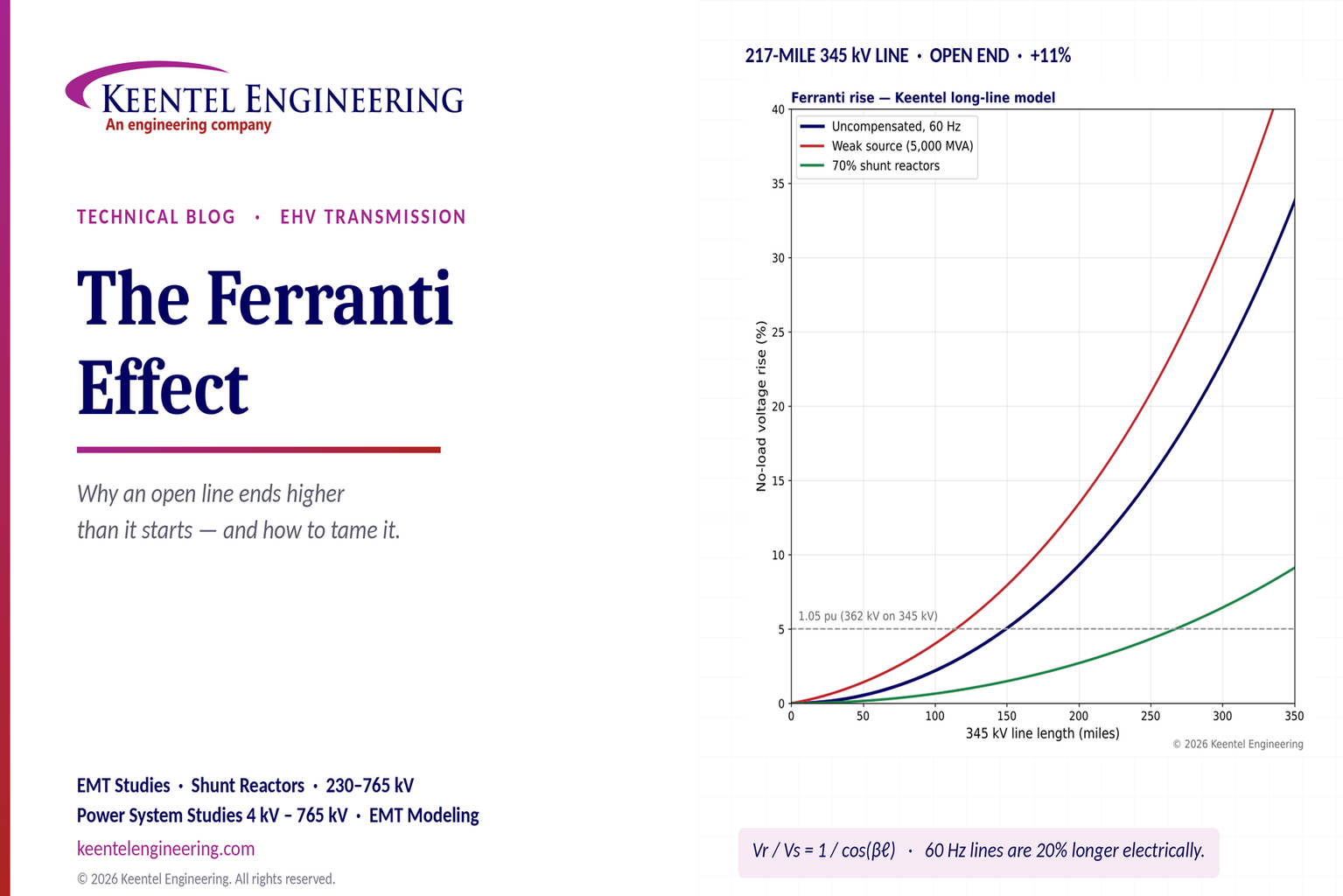
Explore the Ferranti effect in EHV transmission lines: voltage rise, 345 kV examples, switching overvoltages, shunt reactor sizing and mitigation.
By SANDIP R PATEL
•
October 21, 2026
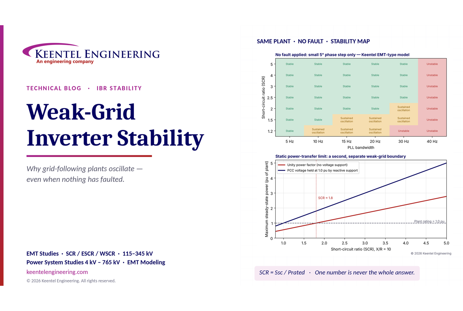
Learn why grid-following inverters become unstable without grid faults. Explore SCR, PLL interactions, EMT studies, grid strength, and mitigation.
By SANDIP R PATEL
•
October 21, 2026
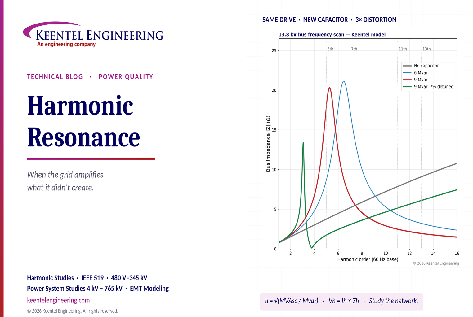
Learn how harmonic resonance amplifies distortion in power systems. Explore capacitor banks, detuned reactors, frequency scans, and IEEE 519 solutions.
By SANDIP R PATEL
•
October 20, 2026
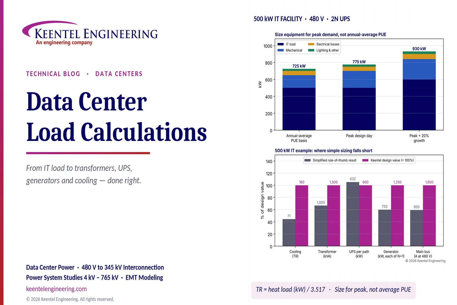
Learn data center electrical load calculations, including IT demand, PUE, UPS and generator sizing, cooling loads, redundancy, and worked US examples.
By SANDIP R PATEL
•
October 20, 2026
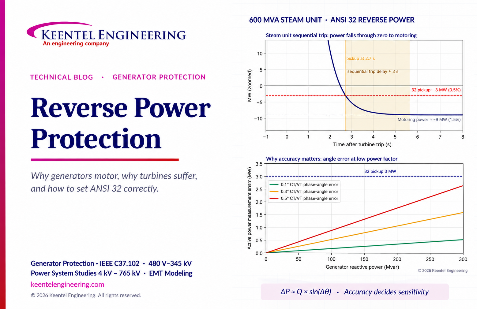
Learn reverse power protection (ANSI 32), generator motoring, relay pickup settings, time delays, sequential tripping and testing for US power plants.
Copy

By Team 2 Dexora
•
October 20, 2026
Explore grounding system testing with Keentel Engineering. Learn IEEE 80/81 methods, soil resistivity, ground resistance, and touch and step voltage safety.

By SANDIP R PATEL
•
October 13, 2026
Plan data center capacity with land screening, MW-per-acre estimates, grid power availability and interconnection feasibility studies from Keentel Engineering.

By SANDIP R PATEL
•
October 11, 2026
Learn which fault produces the highest current at a bus, why SLG faults can exceed three-phase faults, and how symmetrical components determine fault duty.

By SANDIP R PATEL
•
October 11, 2026
Learn why zero-sequence current pulsates in the dq0 frame, how Park's transformation works, and how inverter controls handle unbalance and ground faults.





