
A Coordinated Electric System Interconnection Review—the utility’s deep-dive on technical and cost impacts of your project.
Challenge: Frequent false tripping using conventional electromechanical relays
Solution: SEL-487E integration with multi-terminal differential protection and dynamic inrush restraint
Result: 90% reduction in false trips, saving over $250,000 in downtime
Generation Injection & Large Load Withdrawal
Jun 11, 2026 | Blog
Executive Summary
Connecting a new generation facility or large industrial load to the transmission grid is one of the most technically complex, commercially consequential, and time-sensitive activities in the energy sector. Whether the project involves a power plant seeking to inject energy into the grid or a large industrial facility requiring substantial load withdrawal — such as a steel plant, data center, or manufacturing complex — the interconnection process demands deep technical expertise, precise engineering analysis, and thorough knowledge of utility and ISO procedures.
This white paper provides a technical overview of the generation injection and load withdrawal interconnection study process, explains the key analytical disciplines involved, and describes how Keentel Engineering's specialized services guide developers, industrials, and utilities through every phase — from initial Point of Interconnection (POI) screening to final application submission.
Keentel Engineering's interconnection study services are designed to deliver one clear outcome: identify the best available Point of Interconnection for the client's asset, prepare all required technical models and documentation, and support a successful interconnection application — faster and more cost-effectively than conventional approaches.
1. Understanding Transmission Interconnection
1.1 What Is a Transmission Interconnection?
A transmission interconnection is the physical and contractual connection of a new facility — either a generation source or a large load — to the high-voltage transmission network. This connection allows the facility to exchange power with the broader grid: generators inject power into the network for delivery to consumers, while large loads withdraw power from the network to meet their operational demand.
Unlike distribution-level connections, transmission interconnections involve high-voltage infrastructure (typically 69 kV and above), complex
power flow interactions with the broader regional network, and formal regulatory processes administered by Independent System Operators (ISOs), Regional Transmission Organizations (RTOs), and Transmission Owners (TOs). The interconnection process is governed by FERC regulations, NERC reliability standards, and the specific tariffs and procedures of the applicable utility or ISO.
1.2 Generation Injection vs. Load Withdrawal — Key Differences
While both generation injection and load withdrawal interconnections share many common study requirements, they present distinct technical challenges that must be addressed through specialized analysis:
| Characteristic | Generation Injection | Load Withdrawal |
|---|---|---|
| Primary Impact | Increases fault current, affects voltage profiles, and alters power flow patterns — potentially overloading transmission lines | Draws reactive and real power from the network, depresses voltage at the POI and adjacent buses, increases thermal loading |
| Reactive Power | Generator must meet ISO/utility reactive capability requirements (P-Q curve compliance) | Load requires reactive compensation to maintain acceptable power factor and voltage |
| System Strength | SCR and system strength at the POI is critical — especially for inverter-based generation | System strength less critical for load but voltage regulation and flicker (for arc furnaces) are key concerns |
| Dynamic Modeling | Full dynamic model required: machine, exciter, governor, PSS, or IBR models | Composite load model required: motor load, arc furnace, protection settings |
| Application Process | Processed through ISO/RTO Generator Interconnection Procedures (GIP) | Processed through utility Large Load Interconnection Procedures (LLIP) |
| Key Risk | Generator tripping, voltage oscillations, protection coordination | Voltage collapse under contingency, power factor penalties, flicker emissions |
1.3 The Co-Located Facility Challenge
Projects involving both a large generation facility and a large industrial load at the same site — such as a power plant co-located with a steel plant or industrial complex — present a uniquely complex interconnection scenario. The combined injection and withdrawal must be studied simultaneously to understand:
- Net import and net export operating conditions across all combinations of generation output and load demand
- The facility's aggregate impact on the transmission network under all operating modes
- Whether a hybrid interconnection application or separate applications for each facility is the more efficient approach
- How the generation injection offsets or exacerbates the load withdrawal impacts on the network
Keentel Engineering specializes in this combined facility interconnection scenario, having developed structured analytical workflows that address the full complexity of simultaneous injection and withdrawal studies within a single, integrated study framework.
2. The Transmission Interconnection Process
2.1 Overview of the Process
The interconnection process follows a structured sequence of activities — from initial site and POI assessment through formal application, utility study, and ultimately Interconnection Agreement execution. Understanding this process is essential for developers and industrials to plan their project timelines and budgets effectively.
| Phase | Activity | Who Performs It |
|---|---|---|
| 1 | POI Screening & Pre-Application Study | Client-side engineer (Keentel) — pre-screening using network data and PSS/E to identify and rank candidate POIs before any utility engagement |
| 2 | Pre-Application Meeting with Utility/ISO | Client-side engineer (Keentel) supports — meeting with the utility/ISO to confirm POI, discuss study assumptions, and align on application strategy |
| 3 | Interconnection Application Submission | Client-side engineer (Keentel) prepares — all application forms, technical appendices, facility models, and supporting documentation submitted to utility/ISO |
| 4 | Feasibility Study (if required) | Utility/ISO performs — preliminary assessment of the application. Fees paid by the applicant to the utility/ISO. Not performed by Keentel |
| 5 | System Impact Study (SIS) | Utility/ISO performs — formal transmission planning study to identify network upgrades required. Fees paid by applicant. Not performed by Keentel |
| 6 | Facilities Study | Utility/ISO performs — detailed engineering of specific network upgrades. Fees paid by applicant. Not performed by Keentel |
| 7 | Interconnection Agreement (IA) Negotiation | Client and utility/ISO — Keentel provides technical support during IA negotiations |
| 8 | Construction & Energization | Utility/ISO and client — physical construction of network upgrades and facility interconnection |
3. Keentel Engineering's Interconnection Study Services
Keentel Engineering provides end-to-end client-side interconnection study services across six core technical disciplines. Each discipline addresses a specific aspect of the interconnection analysis required to select the optimal POI, prepare complete application documentation, and support the client through the utility/ISO process.
3.1 POI Screening & Selection
The starting point of every interconnection engagement is the identification and ranking of candidate Points of Interconnection. Keentel's POI screening process is a structured, multi-stage analysis that evaluates candidate nodes across the applicable transmission network against a comprehensive set of technical and commercial criteria.
Stage 1 — Geographic & Network Screening
Candidate POIs are identified by filtering all substations and transmission nodes within the relevant geographic area at applicable voltage levels. The initial candidate pool is assessed against available capacity headroom, planned network changes, active interconnection queue positions, and estimated network upgrade cost exposure. This stage typically narrows a broad initial pool of 15–25 candidates to a focused shortlist of 5–8 technically viable POIs.
Stage 2 — Power Flow Validation in PSS/E
Shortlisted POIs are validated using PSS/E — the industry-standard transmission planning and simulation software — loaded with current and future-year network data for the applicable ISO/utility system. New facility models for the generation injection and/or load withdrawal are built and injected into the network model at each candidate POI, and preliminary power flow checks confirm basic technical feasibility.
Stage 3 — Ranked POI Recommendation
All evaluated POIs are ranked and presented in a comparative POI Ranking Table scoring each candidate against: available capacity, estimated network upgrade cost, queue position, voltage compliance, system strength, application timeline, and jurisdiction suitability. A clear, justified recommendation for the optimal POI is provided — giving the client a single, well-supported answer rather than a list of options to navigate independently.
3.2 Steady-State Power Flow Analysis
AC power flow simulations are performed in PSS/E across the full range of facility operating scenarios to assess the transmission network's response to the new injection or withdrawal under normal conditions:
- Peak load (Heavy Summer) and light load (Light Winter) study cases
- Maximum and partial generation export scenarios (for generation injection)
- Maximum and partial load demand scenarios (for load withdrawal)
- Combined simultaneous operation scenarios (for co-located facilities)
- Net import and net export conditions across all combined operating modes
Power flow results identify thermal overloads on
transmission lines and transformers, voltage violations at the POI and adjacent buses, and the first limiting system element that constrains load service or generation deliverability. These findings directly inform POI selection and preliminary network upgrade identification.
3.3 N-1 Contingency Screening
N-1 contingency screening is performed in PSS/E to assess the network's response to the loss of a single transmission element under the new facility's operating conditions. This is a client-side pre-screening study to support POI selection — it is not a full NERC TPL-001 transmission planning study, which is the utility/ISO's responsibility.
The contingency screening set includes key transmission line outages, transformer outages, largest generator loss events, and facility-specific contingencies. For each contingency, PSS/E evaluates thermal loading on key transmission elements, bus voltage levels near the POI, and system stability indicators. Results are used to rank POI candidates and identify preliminary network upgrade requirements.
3.4 Short Circuit & Breaker Duty Analysis
Short circuit analysis quantifies the fault current contribution from the new generation or load facility at each candidate POI and assesses its impact on existing network equipment. This is performed as a client-side pre-screening study using PSS/E's short circuit module and serves two purposes: informing POI selection and developing the short circuit models required for the interconnection application package.
For Generation Injection
Generator fault current contribution is modeled using correct subtransient reactance and fault current injection profiles. Three-phase bolted and single line-to-ground fault studies are performed at each candidate POI to assess fault current levels, breaker interrupting duty adequacy, and bus fault duty compliance.
For Load Withdrawal
Large industrial loads — particularly those containing arc furnaces, large motors, and variable-speed drives — can make significant fault current contributions that must be accurately modeled. Composite load impedance and motor contribution characteristics are incorporated into the fault study model to produce a realistic assessment of the facility's fault current impact.
3.5 Reactive Power & Voltage Compliance Assessment
Reactive power management is one of the most critical — and most frequently underestimated — aspects of both generation injection and large load withdrawal interconnections.
For Large Load Withdrawal
Steel plants, data centers, manufacturing facilities, and other large industrial loads typically operate at lagging power factors and impose significant reactive power demands on the transmission network. Keentel assesses reactive power requirements across the full load range, evaluates voltage regulation performance at the POI, and sizes reactive compensation systems — including capacitor banks, STATCOMs, and synchronous condensers — to meet ISO/utility voltage and power factor standards. Where arc furnaces are present, dynamic reactive compensation requirements and flicker emission assessment are also addressed.
For Generation Injection
Generators are required by MISO, TVA, and other ISOs to demonstrate reactive capability compliance through P-Q curve analysis. Keentel assesses the generator's full reactive capability envelope, evaluates voltage control mode options, and prepares the reactive capability documentation required for the interconnection application. Where the generator's native reactive capability is insufficient to meet ISO requirements, supplemental reactive support options are identified and sized.
3.6 System Strength & Short Circuit Ratio (SCR) Assessment
System strength — measured through Short Circuit Ratio (SCR) and Weighted Average Short Circuit Ratio (WASCR) — is an increasingly critical study requirement for generator interconnections as the North American grid transitions to higher proportions of inverter-based resources. A low SCR at the POI can cause voltage instability, active power oscillations, and protection coordination failures that threaten both the generating facility and the broader network.
Keentel's SCR assessment calculates the short circuit capacity at each candidate POI relative to the rated MW output of the generation facility, evaluates interactions with nearby inverter-based resources, and compares SCR values across Heavy Summer and Light Winter study cases. Where SCR thresholds are not met, Keentel identifies mitigation options including alternative POI selection, synchronous condenser installation, and grid-forming inverter control strategies.
A comparative SCR assessment across multiple candidate POIs is one of the most valuable outputs of Keentel's pre-screening study — enabling the client to select a POI with adequate system strength before investing in formal utility study costs.
3.7 PSS/E Dynamic Model Development
PSS/E dynamic models are a mandatory submission requirement for formal interconnection applications with MISO, TVA, and most other ISOs and utilities. These models allow the utility and ISO to simulate the transient behavior of the new facility under system disturbances — a requirement that cannot be waived and must be completed before an application can advance to System Impact Study.
Power Plant — Generation Dynamic Models
Keentel develops complete PSS/E dynamic model packages for generation facilities including:
- Machine model: generator electromechanical characteristics (GENROU, GENSAL, or equivalent)
- Excitation system model: automatic voltage regulator and excitation control (EXAC1, ESST1A, or equivalent)
- Governor / prime mover model: turbine-governor speed control response (GGOV1, IEEEG1, or equivalent)
- Power System Stabilizer (PSS): oscillation damping controls where required by the applicable ISO/utility
- Inverter-based resource (IBR) models: generic renewable energy system models (REGC_A, REEC_A, REPC_A) or manufacturer user-defined models (UDMs) for solar, wind, and battery storage facilities
Steel Plant / Industrial Load — Composite Load Dynamic Models
Accurate composite load dynamic models are required for large industrial loads and are developed by Keentel to include:
- Composite load model (CMPLDW or CMLD): representing the full industrial load mix including arc furnaces, large induction motors, and other load components
- Motor load representation: large motor load fraction, inertia, and protection settings affecting post-fault voltage recovery
- Arc furnace dynamic model: flicker generation and dynamic reactive power demand characteristics
- Load protection models: under-voltage load shedding and motor protection relay representations
All dynamic models are validated through standard PSS/E simulation test cases — including 3-phase fault, SLG fault, and generator trip events — and packaged in the format required by the applicable ISO/utility for formal application submission.
3.8 Interconnection Application Support
Keentel provides complete interconnection application support from pre-application strategy through submission-readiness review. This covers:
- Application strategy: advising on the optimal application pathway — including hybrid vs. separate applications for co-located facilities and MISO vs. TVA jurisdiction selection
- Application form preparation: completing all applicable ISO/utility application forms including MISO Generator Interconnection Request, TVA Transmission Service and Generator Interconnection forms, and large load application forms as applicable
- Technical appendices: facility one-line diagrams, POI description, load/generation profiles, operating assumptions, preliminary protection philosophy, and reactive capability documentation
- Pre-application meetings: leading or supporting pre-application meetings with the utility/ISO to confirm POI, discuss study assumptions, and align on application scope
- Submission-readiness review: final completeness check against ISO/utility requirements before submission
- Post-submission coordination: responding to utility/ISO technical information requests, reviewing study notices, and providing technical advisory support throughout the formal study process
4. Why POI Selection Is the Most Important Decision
The choice of Point of Interconnection is the single most consequential technical and commercial decision in the entire interconnection process. It determines the network upgrade costs the project will be required to fund, the interconnection timeline, the system strength environment the generation facility will operate in, and ultimately the economic viability of the project. Yet many developers and industrials underinvest in pre-application POI analysis — proceeding directly to formal utility application without adequate pre-screening, only to encounter unexpected and costly network upgrade requirements at the System Impact Study stage.
4.1 The Cost Impact of POI Selection
Network upgrade costs — which the interconnecting party is typically required to fund as a condition of interconnection — can vary by tens of millions of dollars depending on POI selection. A POI that requires reconductoring of a heavily loaded transmission line will carry significantly higher upgrade costs than an adjacent substation with adequate spare capacity. Without rigorous pre-screening, developers risk entering the formal utility study process at a POI that is commercially unviable — incurring application fees, study fees, and delays before the true cost exposure is revealed.
Keentel's POI screening identifies the lowest-cost, highest-capacity interconnection pathway before a single dollar is spent on formal utility study fees — enabling confident go/no-go decisions early in the project development process.
4.2 The Queue Position Challenge
The interconnection queue is a critical factor in POI selection that is often overlooked. Each ISO and utility maintains a queue of pending interconnection applications, and projects earlier in the queue have priority over network capacity and upgrade cost allocation. A POI that appears technically attractive may be heavily contested by prior queue positions, resulting in high estimated upgrade costs that reflect the project's queue position relative to competing applications.
Keentel's pre-screening process incorporates real-time queue position data for all candidate POIs, enabling the client to identify nodes with minimal queue exposure and better upgrade cost prospects — a factor that can make or break the economic case for a given POI.
4.3 Dual Jurisdiction Considerations
Projects located in areas served by multiple transmission owners or ISOs — such as the boundary between MISO and TVA territory in the Southeast, or areas where multiple utilities overlap — must evaluate POI options across both jurisdictions. The optimal POI may lie in a different jurisdiction than initially assumed, with significantly different upgrade cost profiles, queue dynamics, and application timelines. A thorough cross-jurisdictional POI screening is essential to ensure the best available option is identified regardless of utility boundaries.
5. Technical Deep Dive — Key Study Concepts
5.1 Power Flow Fundamentals for Interconnection
AC power flow analysis is the foundation of all transmission interconnection studies. In PSS/E, the network is represented as a system of buses (nodes) connected by branches (transmission lines and transformers), each with defined impedance, thermal rating, and voltage characteristics. The power flow solver iterates to find the steady-state voltage magnitudes and angles at all buses that satisfy Kirchhoff's laws and the network's physical constraints.
For a new generation injection, the facility is represented as a PV bus — where real power output and terminal voltage are specified, and the solver calculates the reactive power exchange and network voltage profile. For a large load withdrawal, the facility is represented as a PQ bus — where real and reactive power demand are specified, and the solver calculates the voltage response at the POI and throughout the network. The key outputs for POI assessment are:
- Thermal loading on all transmission elements as a percentage of their normal and emergency ratings
- Voltage magnitudes at all buses — violations of ANSI C84.1 voltage standards are flagged
- Reactive power flows and reactive margin at the POI
- Real and reactive power losses in the transmission system
5.2 Short Circuit Fundamentals
Short circuit analysis calculates the fault current that would flow in the network following a bolted fault at a specific bus. The two most important fault types for interconnection studies are:
- Three-phase bolted fault (3φ): the symmetrical fault that produces maximum fault current at the fault location — used to assess breaker interrupting capability
- Single line-to-ground fault (SLG): typically the most severe asymmetrical fault type for protection system design and zero-sequence analysis
For a new generation facility, fault current contribution is determined by the generator's subtransient reactance (X"d) and the network impedance between the generator and the fault location. For a large industrial load containing motors, the motor impedance and inertia determine the magnitude and duration of the motor's fault current contribution — which can be significant for large electric arc furnace and motor drive installations.
The key metric from short circuit analysis is the X/R ratio at the POI — a high X/R ratio indicates a predominantly inductive fault current that stresses breaker interrupting capability. Breaker interrupting duty is assessed by comparing the calculated fault current against the breaker's rated symmetrical interrupting current, adjusted for the X/R ratio per IEEE C37 standards.
5.3 System Strength & SCR — Technical Explanation
Short Circuit Ratio (SCR) is defined as the ratio of the short circuit MVA at the POI to the rated MVA of the connecting generation facility. A high SCR indicates a strong grid — one that is relatively unaffected by the generator's output fluctuations. A low SCR indicates a weak grid, where the generator's output can cause significant voltage fluctuations and where inverter-based resources may experience control instability.
The NERC guideline threshold for minimum SCR is generally 1.5 for inverter-based resources, though specific requirements vary by ISO and utility. MISO, for example, has published specific system strength assessment requirements tied to its interconnection procedures. Where SCR falls below the minimum threshold, the following mitigation options are typically evaluated:
- Synchronous condenser: a rotating electrical machine that provides reactive power and increases short circuit capacity at the POI — directly raising the SCR
- Grid-forming inverter controls: advanced inverter control strategies that allow inverter-based resources to form voltage references in weak grid conditions — an emerging technology increasingly accepted by utilities
- Alternative POI selection: moving the interconnection to a stronger point in the network with higher inherent short circuit capacity
- Phased generation commissioning: initially operating at reduced output levels until network strengthening upgrades are completed
5.4 Reactive Power & Power Factor — Why It Matters for Large Loads
Large industrial loads — particularly steel plants with electric arc furnaces — impose variable and often highly reactive power demands on the transmission network. This has two significant consequences: power factor penalties imposed by the utility for operating below a specified minimum power factor, and voltage depression and flicker on the network that can affect other customers served by the same transmission infrastructure.
The power factor of an electric arc furnace load varies dynamically as the furnace operates through its melting cycle, generating rapid and large reactive power swings that manifest as voltage flicker on the network. Flicker assessment — quantified using the IEC flicker severity indices Pst (short-term flicker severity) and Plt (long-term flicker severity) — is a standard utility requirement for arc furnace interconnections and directly drives the sizing of dynamic reactive compensation (STATCOM or SVC) requirements.
For generation facilities, reactive capability compliance is a contractual requirement in virtually all ISO/utility interconnection agreements. The generator must demonstrate the ability to operate within a specified power factor range at its high-side bus across its full real power output range — typically 0.95 power factor leading to 0.90 power factor lagging at rated MW output. Failure to demonstrate this capability during the formal study process can delay the interconnection agreement and trigger requirements for additional reactive support equipment.
6. How Keentel Engineering Supports Your Project
Keentel Engineering serves as the client's dedicated technical partner throughout the pre-application and application phases of the interconnection process. Our role is to ensure that the client enters the formal utility study process with the best possible POI, the most complete and technically robust application, and the highest likelihood of a successful interconnection outcome.
| What We Do | Value Delivered to the Client |
|---|---|
| Screen candidate POIs across the full network | Identify the lowest-cost, highest-capacity interconnection options before committing to a site or filing an application — avoiding costly surprises in the utility study process |
| Perform PSS/E power flow & contingency screening | Confirm technical feasibility at each candidate POI and identify limiting system elements — enabling data-driven POI selection decisions |
| Assess fault current impacts | Quantify fault current contributions from the new facility and identify any equipment deficiencies at candidate POIs — reducing application rejection risk |
| Develop PSS/E dynamic models | Prepare mandatory dynamic model submission packages for generation and load facilities — ensuring application completeness from day one |
| Assess SCR & system strength | Identify weak-grid risks at candidate POIs and recommend mitigation strategies — protecting the client's generation investment from post-IA performance issues |
| Prepare interconnection applications | Produce complete, technically rigorous application packages for MISO, TVA, or other applicable ISO/utility — maximizing the probability of first-submission acceptance |
| Support utility/ISO coordination | Act as the client's technical advisor throughout pre-application meetings, technical clarification calls, and study reviews — ensuring the client's interests are represented effectively |
Keentel Engineering's interconnection study services are built on one principle: the client's best interests come first. We provide honest, technically rigorous analysis — not the answer the client wants to hear, but the answer they need to make informed decisions.
7. Frequently Asked Questions (FAQ)
The following questions are commonly raised by developers, industrial clients, and project owners during the interconnection study process. Keentel Engineering's answers are provided to help clients better understand the technical and commercial dimensions of the process.
Q: What is the difference between a client-side interconnection study and a utility System Impact Study (SIS)?
A client-side study — such as those performed by Keentel — is a pre-screening analysis conducted on behalf of the developer or industrial client to identify the best POI, prepare application documentation, and develop the technical models required for submission. It uses the same software (PSS/E) and network data as the utility, but it is not a formal regulatory study. A System Impact Study (SIS) is performed by the utility or ISO after application submission and is the formal study that determines the network upgrades the applicant is required to fund. The SIS carries regulatory standing; the client-side study does not. Both are necessary — the client-side study enables a better application, and the SIS determines the formal upgrade obligations.
Q: How long does the transmission interconnection process take from start to finish?
The full interconnection process — from initial POI screening to an executed Interconnection Agreement — typically takes 18 months to 5+ years depending on the ISO/utility, queue congestion, and project complexity. The client-side pre-screening phase (Keentel's scope) typically takes 4–8 weeks. The formal utility study phases (Feasibility Study, SIS, Facilities Study) are outside Keentel's control and can take 12–48 months depending on queue position and study complexity. Early, high-quality client-side studies reduce the risk of delays and study restarts during the formal utility process.
Q: What happens if the utility's System Impact Study results differ from Keentel's pre-screening findings?
Differences between client-side pre-screening results and formal utility SIS results can occur for several reasons: the utility may use different study assumptions, a more detailed model, or a different study case year. Pre-screening results are directionally accurate and conservative by design, but are not guaranteed to match formal SIS findings exactly. Keentel's pre-screening is intended to inform POI selection and de-risk the application — not to predict SIS results with certainty. When differences arise, Keentel reviews the SIS results and provides technical commentary to help the client understand and respond to utility findings.
Q: Can a generator and a large load at the same site share a single interconnection application?
Yes — this is known as a hybrid interconnection application and is permitted under MISO, TVA, and most other ISO/utility procedures. A hybrid application studies the combined facility as a single interconnection, which can reduce aggregate network upgrade costs by netting the injection and withdrawal impacts. However, hybrid applications are more complex to prepare and administer, and not all utilities encourage them. Keentel recommends a pre-application meeting with the applicable utility/ISO to confirm whether a hybrid or separate application is more appropriate for the specific project configuration.
Q: What data does the client need to provide for Keentel to perform the studies?
The minimum data required includes: Single Line Diagram (SLD) of the facility, rated MW and MVAR capability (for generation) or maximum load demand (for load), facility site coordinates, proposed interconnection voltage level, and equipment nameplate data. For dynamic modeling, additional data is required including excitation system type, governor model, and turbine/motor characteristics. If client data is not available, Keentel applies conservative engineering assumptions subject to client written approval — studies proceed on assumptions and are updated when actual data is provided.
Q: What is a PSS/E dynamic model and why is it required?
PSS/E is the industry-standard power systems simulation software used by ISOs, utilities, and transmission planners across North America. A dynamic model in PSS/E represents the transient behavior of a generation facility or large load under system disturbances — capturing how the facility responds to voltage changes, frequency deviations, and fault events. Dynamic models are mandatory for interconnection applications because the utility needs them to simulate the impact of the new facility on system stability during formal SIS studies. Without compliant dynamic models, an application cannot proceed past the initial submission stage.
Q: What is an interconnection queue and why does it affect our project?
The interconnection queue is the list of all pending interconnection applications at a given ISO or utility, ordered by submission date. Projects that are earlier in the queue have priority over network capacity and are studied ahead of later applicants. When a network upgrade is required, the cost may be shared among multiple queue projects — or borne entirely by one project if it is the only one requiring that upgrade. Queue dynamics can change significantly over time as earlier projects withdraw or advance. Monitoring the queue at candidate POIs before application filing is a key part of Keentel's pre-screening process.
Q: What is the difference between MISO and TVA jurisdiction and how does it affect our interconnection?
MISO (Midcontinent Independent System Operator) is an RTO that administers the interconnection queue and market for a large portion of the central and southern United States, including areas served by Big Rivers Electric Corporation in Kentucky. TVA (Tennessee Valley Authority) is a federal power authority that owns and operates its own transmission network in the Tennessee Valley region, including portions of Kentucky. Projects near the MISO/TVA boundary may have POI options in both jurisdictions — each with different interconnection procedures, study timelines, and upgrade cost structures. Evaluating both jurisdictions in parallel before filing is strongly recommended for projects in boundary areas.
Q: How are network upgrade costs estimated in the pre-screening phase?
Keentel prepares order-of-magnitude network upgrade cost estimates with ±20% accuracy based on benchmarked cost data for comparable transmission infrastructure upgrades — including reconductoring costs per mile, transformer replacement costs by voltage class and MVA rating, and reactive compensation system costs. These estimates are directional indicators to inform POI selection and project economic modeling. Formal, binding network upgrade cost estimates are produced by the utility through the Facilities Study phase of the formal interconnection process — which typically occurs after the SIS and is outside Keentel's scope.
Q: Does Keentel perform transmission planning studies?
No. Keentel performs client-side pre-screening and application support studies — not transmission planning. Transmission planning studies, such as NERC TPL-001 through TPL-006 compliance studies, are performed by Transmission Owners and ISOs as part of their regulatory obligations and as part of the formal System Impact Study process. Keentel's studies are intended to inform the client's interconnection strategy and prepare a strong application — they do not replace, substitute for, or constitute the formal utility transmission planning process.
Final Thoughts
The Texas grid is being asked to host more new load in the next five years than it has built in the last fifty. The legacy single-study, firm-service-only interconnection model cannot deliver that capacity in time.
BYOG, CLR, and WLPUN are the three frameworks Texas is using to bridge the gap — letting Large Loads come online with self-supply and as-available grid service while transmission catches up. They are not interchangeable, and the regulatory boundaries between them are still being drawn through the Batch Zero process scheduled for finalization in mid-2026.
For developers, the implication is clear: the framework you choose determines your speed-to-power, your operational obligations, your settlement exposure, and your capital deployment risk. Understanding the distinctions between BYOG, CLR, and WLPUN — and the constructs that sit beneath each — is no longer a regulatory nicety. It's a core part of building large-scale compute infrastructure in ERCOT.

About the Author:
Sonny Patel P.E. EC
IEEE Senior Member
In 1995, Sandip (Sonny) R. Patel earned his Electrical Engineering degree from the University of Illinois, specializing in Electrical Engineering . But degrees don’t build legacies—action does. For three decades, he’s been shaping the future of engineering, not just as a licensed Professional Engineer across multiple states (Florida, California, New York, West Virginia, and Minnesota), but as a doer. A builder. A leader. Not just an engineer. A Licensed Electrical Contractor in Florida with an Unlimited EC license. Not just an executive. The founder and CEO of KEENTEL LLC—where expertise meets execution. Three decades. Multiple states. Endless impact.
Services

Let's Discuss Your Project
Let's book a call to discuss your electrical engineering project that we can help you with.
About the Author:
Sonny Patel P.E. EC
IEEE Senior Member
In 1995, Sandip (Sonny) R. Patel earned his Electrical Engineering degree from the University of Illinois, specializing in Electrical Engineering . But degrees don’t build legacies—action does. For three decades, he’s been shaping the future of engineering, not just as a licensed Professional Engineer across multiple states (Florida, California, New York, West Virginia, and Minnesota), but as a doer. A builder. A leader. Not just an engineer. A Licensed Electrical Contractor in Florida with an Unlimited EC license. Not just an executive. The founder and CEO of KEENTEL LLC—where expertise meets execution. Three decades. Multiple states. Endless impact.
Leave a Comment
Thank you for contacting us.
We will get back to you as soon as possible.
We will get back to you as soon as possible.
Oops, there was an error sending your message.
Please try again later.
Please try again later.
Related Posts
By SANDIP R PATEL
•
July 23, 2026
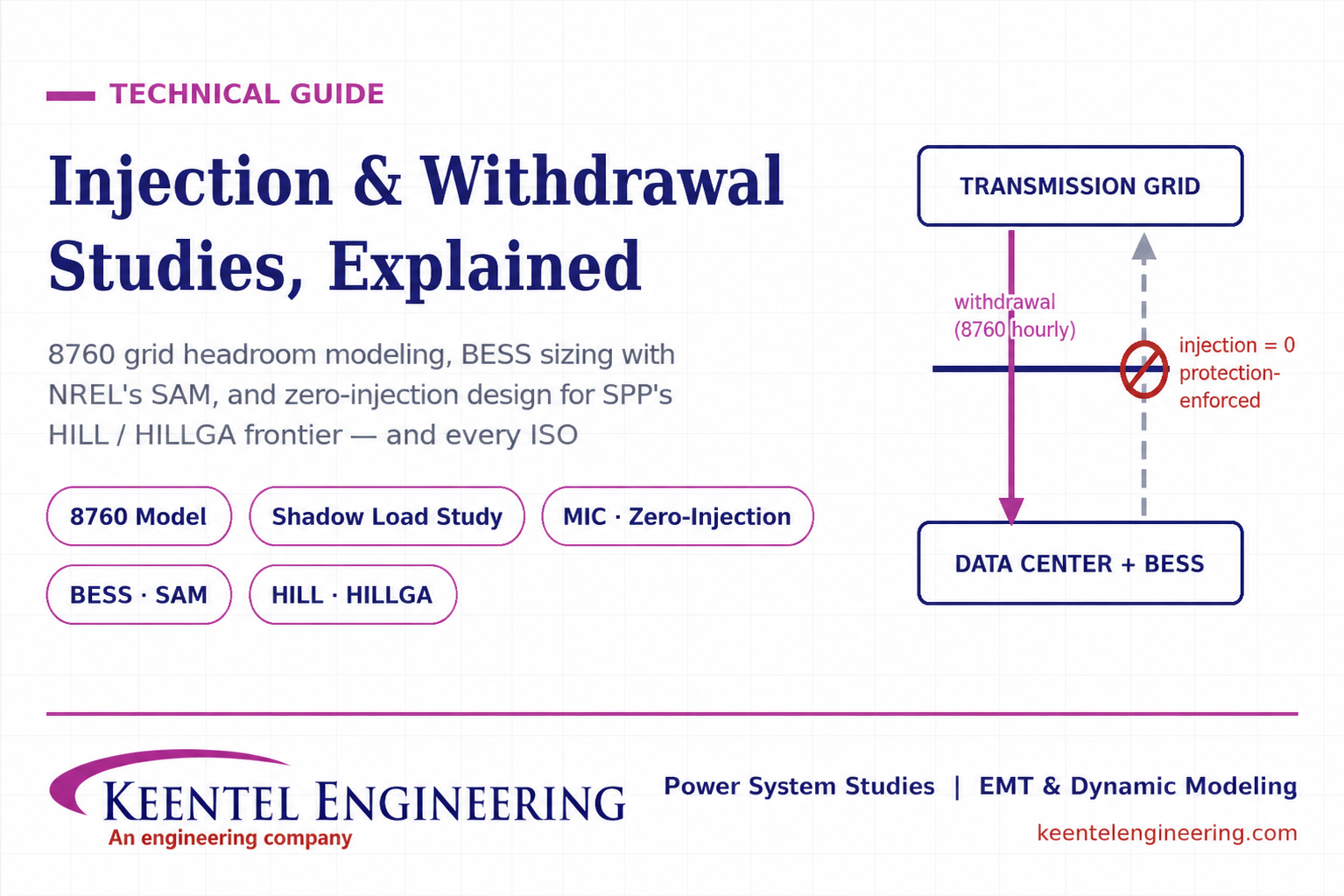
Learn how injection and withdrawal studies, 8760 headroom modeling, zero-injection engineering, and SPP HILLGA improve large load grid interconnections
By SANDIP R PATEL
•
July 21, 2026
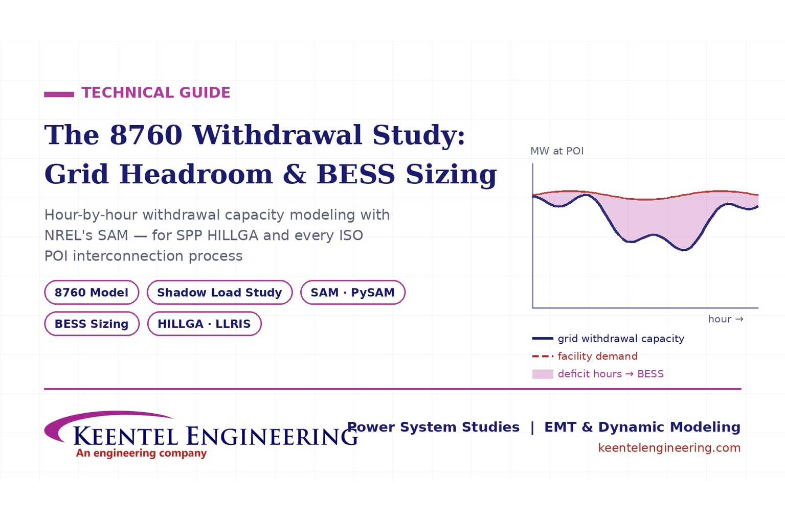
Learn how an 8760 withdrawal study models hourly grid headroom and uses SAM-based BESS sizing for large-load interconnection projects.
By SANDIP R PATEL
•
July 21, 2026
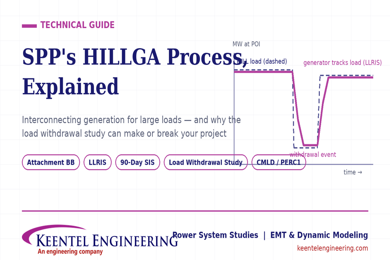
Learn how the SPP HILLGA process supports data center generation interconnection and why an 8760 withdrawal study can determine project success.
By SANDIP R PATEL
•
July 19, 2026
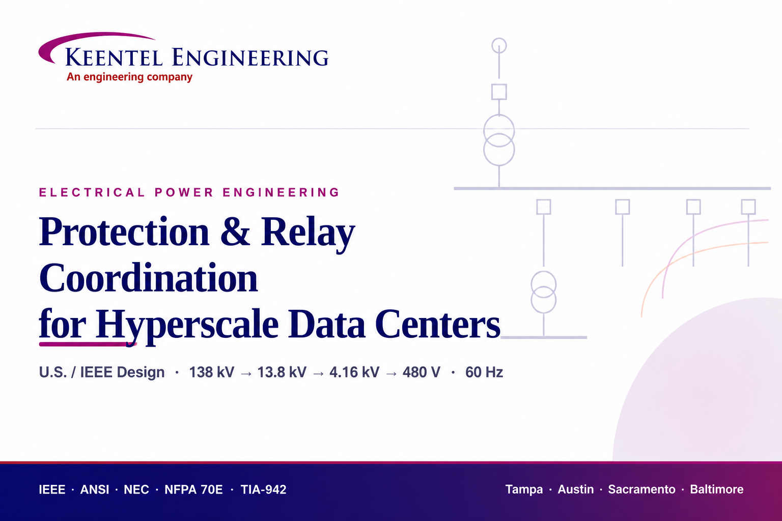
Learn electrical protection and relay coordination for hyperscale data centers with IEEE standards, short-circuit studies, arc-flash analysis, and MV protection.
By SANDIP R PATEL
•
July 18, 2026
Explore Battery Energy Storage System components, including cells, PCS, BMS, EMS, cooling, fire protection, sizing, safety, and grid codes.
By SANDIP R PATEL
•
July 18, 2026
Explore how grid-forming inverters support BESS, synthetic inertia, grid-code compliance, plant sizing, testing, and project revenue.
By SANDIP R PATEL
•
July 18, 2026
Learn how SEL RTAC protection monitoring supports NERC PRC-005 compliance, predictive maintenance alarms, automated reporting, and relay verification.
By SANDIP R PATEL
•
July 17, 2026
Explore utility-scale BESS design from the 10% package to IFC, NFPA 855 compliance, PSS®E/PSCAD models, and ERCOT interconnection.
By SANDIP R PATEL
•
July 17, 2026
Substation design guide, electrical substation design, substation equipment sizing, IEEE 80 grounding design, IEEE 998 lightning shielding, bus configuration design


