
A Coordinated Electric System Interconnection Review—the utility’s deep-dive on technical and cost impacts of your project.
Challenge: Frequent false tripping using conventional electromechanical relays
Solution: SEL-487E integration with multi-terminal differential protection and dynamic inrush restraint
Result: 90% reduction in false trips, saving over $250,000 in downtime
ERCOT enforces all of the above through simulation, which means your model is your compliance case. The bar is now high:
- Whole-facility scope. The model must represent everything the IT load, the UPS and power conversion, the cooling plant, the protection and control systems in formats compatible with ERCOT's study platforms (PSS/E, PSCAD, TSAT).
- Real control loops, not approximations. Generic textbook representations are unacceptable. The model must capture the actual inner control behavior of your power electronics.
- Hardware-validated converter models. For electronic loads, the PSCAD model must be benchmarked against actual hardware testing including voltage ride-through and subsynchronous response. A model assembled from standard PSCAD library blocks fails by definition, because a generic block has never been tested against your vendor's hardware. The good news: validation is a hardware-type test, so results for a given converter product are reusable across every facility that uses it.
- Format migration. Facilities that previously submitted the older composite load model (CMLD) format must transition to EPRI's PERC1 format.
- Three checkpoints. Models are reviewed before the stability study begins (no model, no study), before each quarterly stability assessment, and for electronic loads one final time before energization, when you must submit as-built models with a documented comparison against the previously studied data and a sworn attestation that the model matches actual field settings. ERCOT's review takes 10 business days, extendable by 20 put it on your critical path.
- A living obligation. Change your technology, controls, or relay settings in a way that affects ride-through including converting a crypto mining site to an AI data center — and you've triggered a new interconnection study, even if your megawatts don't change.
| Parameter | Detail |
|---|---|
| System | 230 kV / 138 kV transmission corridors, wind and wet-snow icing exposure |
| Data basis | 15 years of minute-resolution forced-outage records + regional weather observations |
| Core methods | Event grouping, MVA performance curves, time-to-95%-restore, area outage rate curves, fragility modeling, rerun-history benefits, exceedance and log-domain risk metrics |
| Headline result | ≈85% of maximum resilience benefit at 60% of original capital; worst-event restoration window cut from 11 days to 5 in rerun-history terms |
| Decision supported | Capital portfolio selection; resilience plan filing; post-investment verification framework |
| System / Topic | Governing Standard(s) | What It Controls |
|---|---|---|
| Overall plant electrical distribution | IEEE 141 (Red Book); IEEE 666 | Distribution architecture, voltage selection, design of generating station auxiliary service systems |
| Power system studies | IEEE 399 (Brown Book); IEEE 551 | Load flow, symmetrical/asymmetrical short circuit, motor starting methodologies down to the lowest LV panelboard |
| Protection & coordination | IEEE 242 (Buff Book); IEEE 3004.5; IEEE C37 series | Generator relaying (21, 59N, 87G), time-current coordination, selective clearing between LV and MV tiers |
| GSU / UAT / SST transformers | IEEE C57.12.00 and C57 family | Transformer ratings, impedance, testing, loading |
| HV switchyard breakers | IEEE C37.06 | AC high-voltage circuit breaker preferred ratings |
| MV switchgear (13.8 kV) | IEEE C37.20.2; IEEE C37.20.7 | Metal-clad construction, compartmentalization, vacuum breakers; arc-resistant design with plenum venting |
| MV cable | UL 1072; ICEA S-93-639 (NEMA WC 74) | Type MV-105 shielded cable, 133% insulation level for HRG systems |
| LV switchgear (480 V) | IEEE C37.13; UL 1558 | Metal-enclosed LV power circuit breaker switchgear to 635 V, draw-out ACBs with electronic trip units |
| Motor control centers | UL 845; NEMA ICS 18 | LV-MCC construction, MCCB/MCP protection for motors under ~200 HP |
| Motors | NEMA MG-1 | Motor performance, starting characteristics, service factors |
| DC & battery systems | IEEE 485; IEEE 946 | Lead-acid battery sizing (125/250 VDC), DC auxiliary system design |
| Grounding | IEEE 80; IEEE 142 (Green Book) | Ground grid step/touch potential limits; system grounding including high-resistance grounding |
| Lightning protection | IEEE 998 | Direct-stroke shielding of switchyard and outdoor generator structures |
| Arc flash & electrical safety | IEEE 1584; NFPA 70E | Incident energy calculation; worker safety boundaries and PPE |
| Fire protection | NFPA 850 | Fire protection and risk management for combustion turbine generating plants |
| Installation code | NEC (NFPA 70); NESC | Wiring methods inside the plant fence; overhead/outdoor clearances at the switchyard |
| Interconnection & compliance | FERC LGIP; NERC MOD-025/026/027, PRC-019/024/029, FAC-008 | Interconnection process, model validation, protection/ride-through coordination, facility ratings |
| IFC / Construction Deliverable | Purpose |
|---|---|
| Stamped IFC packages | Legal basis for construction; P.E. responsible charge |
| Final relay settings & TCCs | Protection as-installed matches the coordination study |
| Calculation archive | Owner records; NERC audit evidence trail |
| Commissioning procedures | Safe, sequenced energization; MOD field testing |
| Construction support | RFIs, field changes, FAT/SAT witness |
| As-builts & model handoff | Operating baseline; future study currency |
| Metric | Outcome |
|---|---|
| Defects found pre-occupancy | Three topology defects and one settings-mismatch family corrected before load migration; the shared-switchboard defect alone would have invalidated the concurrently-maintainable claim on day one |
| IST findings | Fourteen additional discrepancies surfaced under scenario testing (control logic, alarm mapping, one generator sequencing fault) — all closed before handover instead of during operations |
| Black-building test | Passed on second execution; the first attempt exposed the generator sequencing fault under true block load, exactly the failure the compressed plan would never have found |
| Handover quality | Operations team certified on the actual failure scenarios; corrected EOPs and settings documentation delivered as controlled documents |
| Business outcome | Occupancy proceeded three weeks behind the original date — against an independent estimate that the uncorrected sequencing fault carried a high probability of a full facility outage within the first year |
Part 2 — Frequently Asked Questions: Large Load Interconnection
| Contact | Details |
|---|---|
| Headquarters | 400 N Ashley Dr STE 2600, Tampa, FL 33602 |
| Phone | (813) 389-7871 |
| contact@keentelengineering.com | |
| Florida Firm Registration | No. 36853 |
| Additional Offices | Austin, TX • Sacramento, CA • Baltimore, MD |
| Who | Acronym | Plain-English Role |
|---|---|---|
| ERCOT | — | The grid's air traffic controller. It doesn't own power lines or plants; it directs the flow of electricity across most of Texas and referees the admission process for new generators. |
| Interconnecting Entity | IE | You — the developer or owner trying to connect a new plant (or significantly modify an existing one). You file the application and drive the process. |
| Resource Entity | RE | The registered owner/operator of the generator once it becomes an official market participant. Often the same company as the IE, wearing a different hat. |
| Qualified Scheduling Entity | QSE | Your plant's voice on the grid. The QSE handles round-the-clock communications with ERCOT — telemetry, schedules, dispatch instructions. Every generator must have one. |
| Transmission Service Provider | TSP | The utility that owns the wires and substation you'll connect to. The TSP runs your detailed study, builds the connection facilities, and signs your interconnection contract. |
| RIOO-IS | — | ERCOT's online portal where the whole process lives — applications, documents, status tracking, and checklists all flow through it. |
| Who | Acronym | Plain-English Role |
|---|---|---|
| ERCOT | — | The grid's air traffic controller. It doesn't own power lines or plants; it directs the flow of electricity across most of Texas and referees the admission process for new generators. |
| Interconnecting Entity | IE | You — the developer or owner trying to connect a new plant (or significantly modify an existing one). You file the application and drive the process. |
| Resource Entity | RE | The registered owner/operator of the generator once it becomes an official market participant. Often the same company as the IE, wearing a different hat. |
| Qualified Scheduling Entity | QSE | Your plant's voice on the grid. The QSE handles round-the-clock communications with ERCOT — telemetry, schedules, dispatch instructions. Every generator must have one. |
| Transmission Service Provider | TSP | The utility that owns the wires and substation you'll connect to. The TSP runs your detailed study, builds the connection facilities, and signs your interconnection contract. |
| RIOO-IS | — | ERCOT's online portal where the whole process lives — applications, documents, status tracking, and checklists all flow through it. |
| Who | Acronym | Plain-English Role |
|---|---|---|
| ERCOT | — | The grid's air traffic controller. It doesn't own power lines or plants; it directs the flow of electricity across most of Texas and referees the admission process for new generators. |
| Interconnecting Entity | IE | You — the developer or owner trying to connect a new plant (or significantly modify an existing one). You file the application and drive the process. |
| Resource Entity | RE | The registered owner/operator of the generator once it becomes an official market participant. Often the same company as the IE, wearing a different hat. |
| Qualified Scheduling Entity | QSE | Your plant's voice on the grid. The QSE handles round-the-clock communications with ERCOT — telemetry, schedules, dispatch instructions. Every generator must have one. |
| Transmission Service Provider | TSP | The utility that owns the wires and substation you'll connect to. The TSP runs your detailed study, builds the connection facilities, and signs your interconnection contract. |
| RIOO-IS | — | ERCOT's online portal where the whole process lives — applications, documents, status tracking, and checklists all flow through it. |
| Who | Acronym | Plain-English Role |
|---|---|---|
| ERCOT | — | The grid's air traffic controller. It doesn't own power lines or plants; it directs the flow of electricity across most of Texas and referees the admission process for new generators. |
| Interconnecting Entity | IE | You — the developer or owner trying to connect a new plant (or significantly modify an existing one). You file the application and drive the process. |
| Resource Entity | RE | The registered owner/operator of the generator once it becomes an official market participant. Often the same company as the IE, wearing a different hat. |
| Qualified Scheduling Entity | QSE | Your plant's voice on the grid. The QSE handles round-the-clock communications with ERCOT — telemetry, schedules, dispatch instructions. Every generator must have one. |
| Transmission Service Provider | TSP | The utility that owns the wires and substation you'll connect to. The TSP runs your detailed study, builds the connection facilities, and signs your interconnection contract. |
| RIOO-IS | — | ERCOT's online portal where the whole process lives — applications, documents, status tracking, and checklists all flow through it. |
| Who | Acronym | Plain-English Role |
|---|---|---|
| ERCOT | — | The grid's air traffic controller. It doesn't own power lines or plants; it directs the flow of electricity across most of Texas and referees the admission process for new generators. |
| Interconnecting Entity | IE | You — the developer or owner trying to connect a new plant (or significantly modify an existing one). You file the application and drive the process. |
| Resource Entity | RE | The registered owner/operator of the generator once it becomes an official market participant. Often the same company as the IE, wearing a different hat. |
| Qualified Scheduling Entity | QSE | Your plant's voice on the grid. The QSE handles round-the-clock communications with ERCOT — telemetry, schedules, dispatch instructions. Every generator must have one. |
| Transmission Service Provider | TSP | The utility that owns the wires and substation you'll connect to. The TSP runs your detailed study, builds the connection facilities, and signs your interconnection contract. |
| RIOO-IS | — | ERCOT's online portal where the whole process lives — applications, documents, status tracking, and checklists all flow through it. |
| Who | Acronym | Plain-English Role |
|---|---|---|
| ERCOT | — | The grid's air traffic controller. It doesn't own power lines or plants; it directs the flow of electricity across most of Texas and referees the admission process for new generators. |
| Interconnecting Entity | IE | You — the developer or owner trying to connect a new plant (or significantly modify an existing one). You file the application and drive the process. |
| Resource Entity | RE | The registered owner/operator of the generator once it becomes an official market participant. Often the same company as the IE, wearing a different hat. |
| Qualified Scheduling Entity | QSE | Your plant's voice on the grid. The QSE handles round-the-clock communications with ERCOT — telemetry, schedules, dispatch instructions. Every generator must have one. |
| Transmission Service Provider | TSP | The utility that owns the wires and substation you'll connect to. The TSP runs your detailed study, builds the connection facilities, and signs your interconnection contract. |
| RIOO-IS | — | ERCOT's online portal where the whole process lives — applications, documents, status tracking, and checklists all flow through it. |
| Who | Acronym | Plain-English Role |
|---|---|---|
| ERCOT | — | The grid's air traffic controller. It doesn't own power lines or plants; it directs the flow of electricity across most of Texas and referees the admission process for new generators. |
| Interconnecting Entity | IE | You — the developer or owner trying to connect a new plant (or significantly modify an existing one). You file the application and drive the process. |
| Resource Entity | RE | The registered owner/operator of the generator once it becomes an official market participant. Often the same company as the IE, wearing a different hat. |
| Qualified Scheduling Entity | QSE | Your plant's voice on the grid. The QSE handles round-the-clock communications with ERCOT — telemetry, schedules, dispatch instructions. Every generator must have one. |
| Transmission Service Provider | TSP | The utility that owns the wires and substation you'll connect to. The TSP runs your detailed study, builds the connection facilities, and signs your interconnection contract. |
| RIOO-IS | — | ERCOT's online portal where the whole process lives — applications, documents, status tracking, and checklists all flow through it. |
Electrical Protection and Relay Coordination for Hyperscale Data Centers: A U.S. / IEEE Engineering Guide
Jul 19, 2026 | Blog
By Keentel Engineering — EHV, HV & MV Electrical Power Engineering | Tampa, FL · Austin, TX · Sacramento, CA · Baltimore, MD
Why Protection Engineering Decides Whether a Hyperscale Data Center Stays Online
A hyperscale data center is, electrically, one of the most demanding loads on the North American grid. A single campus can draw 100 to 300 MW continuously, run at a power-usage-effectiveness target that leaves almost no thermal slack, and contractually promise the operator's customers 99.982% availability (Uptime Institute Tier III) or 99.995% availability (Tier IV) — the difference between roughly 1.6 hours and 26 minutes of allowable downtime per year.
At that level, the protection and relay coordination scheme is not a code-compliance checkbox. It is the system that decides, in the first three to five cycles of a fault, whether a bolted short circuit on one 480 V branch trips one molded-case breaker or cascades upstream and drops a data hall. Good coordination isolates the smallest possible section of the network; poor coordination sacrifices selectivity and takes down critical load that was never in fault.
This guide lays out how Keentel Engineering approaches protection and coordination for U.S. hyperscale facilities: the voltage architecture under ANSI C84.1, the IEEE/ANSI/NEC standards that govern the work, a fully worked short-circuit and coordination example on a 138 kV / 13.8 kV / 4.16 kV / 480 V system at 60 Hz, and the arc-flash, grounding, and commissioning decisions that separate a resilient design from one that merely passes plan review. It closes with a detailed FAQ and three anonymized case studies drawn from the kind of work our power-systems group performs for utilities, developers, and EPC partners.
The U.S. Voltage Architecture: 138 kV → 13.8 kV → 4.16 kV → 480/277 V
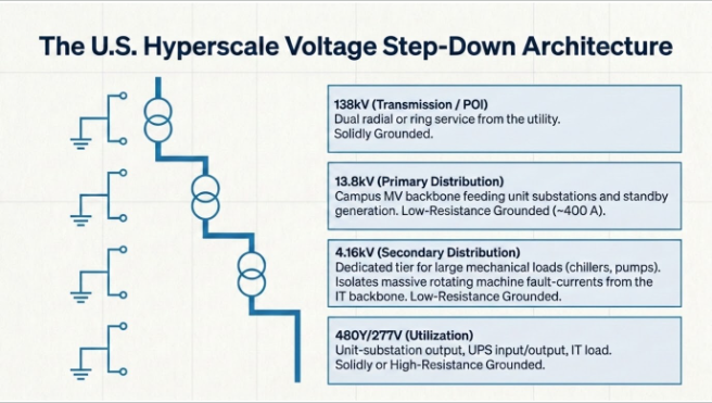
In the United States, the system is designed to ANSI C84.1 nominal voltage classes and operated at 60 Hz, which sets equipment ratings, standard impedances, protective-relay curve families, and the entire standards stack. A representative U.S. hyperscale one-line steps down through four voltage classes:
Level
ANSI C84.1 Nominal
Role in the Data Center
Typical Grounding
Transmission / utility service
138 kV, 60 Hz
Point of interconnection (POI) from the utility; dual radial or ring service
Solidly grounded
Primary distribution
13.8 kV
Campus MV backbone; feeds unit substations and MV standby generation
Low-resistance grounded (~400 A)
Secondary distribution
4.16 kV
Large mechanical loads — chillers, high-capacity pumps, air handlers
Low-resistance grounded (~400 A)
Utilization
480Y/277 V
Unit-substation output; UPS input/output, mechanical MCCs
Solidly or high-resistance grounded
Receptacle / control
208Y/120 V
Lighting, controls, convenience power
Solidly grounded
The two-tier medium-voltage approach — 13.8 kV for the campus backbone and 4.16 kV for large motor loads — is deliberate. Keeping the largest rotating machines on a dedicated 4.16 kV bus limits their fault-current contribution to the 13.8 kV backbone, keeps 480 V utilization transformers a single transformation away from the critical IT load, and gives the coordination engineer more discrete grading steps between the utility and the branch circuit.
Frequency matters more than it appears. At 60 Hz, standard U.S. medium-voltage switchgear is built and tested to IEEE C37.20.2 (metal-clad) with short-circuit ratings from ANSI C37.06 (for example 25 kA, 40 kA, 50 kA, and 63 kA classes), and protective relays apply the inverse-time curve equations of IEEE C37.112. Every interrupting duty, CT saturation check, and curve-coordination step in the design flows directly from these 60 Hz ratings and the ANSI C84.1 voltage classes.
The U.S. Standards Stack (and What Each One Governs)
Protection engineering in the United States draws on a layered set of IEEE, ANSI, NFPA, and infrastructure standards. The table below maps each protection domain to the governing document.
Domain
U.S. / IEEE-ANSI Standard
What It Governs
Device function numbers
IEEE C37.2
ANSI device numbers (50, 51, 87, 21, etc.)
Protective relay ratings & testing
IEEE C37.90 / C37.90.1 / C37.90.2
Relay surge, dielectric, and EMI withstand
Inverse-time curve equations
IEEE C37.112
Moderately / Very / Extremely Inverse curve math
Short-circuit calculation
IEEE 3002.3, ANSI C37.010, C37.13
First-cycle and interrupting duty; breaker application
Protection & coordination methodology
IEEE 3004 series(formerly IEEE 242, "Buff Book")
System protection philosophy
Reliability & availability analysis
IEEE 3006 series(formerly IEEE 493, "Gold Book")
Tier III/IV availability modeling
Grounding
IEEE 142(Green Book), IEEE 80(substation)
System and equipment grounding
Arc-flash incident energy
IEEE 1584-2018
Incident-energy calculation
Electrical safety in the workplace
NFPA 70E
Arc-flash labeling, PPE, work practices
Wiring & overcurrent protection
NEC (NFPA 70)
Article 645 (IT rooms), 700/701/708 (emergency/critical)
Substation & line safety
NESC (ANSI C2)
Clearances, grounding, worker safety
Substation automation & GOOSE
IEC 61850+ DNP3 (IEEE 1815)
Station bus, protection messaging, SCADA
Time synchronization
IEEE 1588 (PTP), IRIG-B
Sub-microsecond relay/merging-unit sync
Data center topology
ANSI/TIA-942, Uptime Institute Tier
Redundancy classification (N, N+1, 2N)
Power quality / harmonics
IEEE 519
Harmonic limits at the PCC
Physical & cyber security
ISO/IEC 27001, NERC CIP
Security of critical cyber assets
For any facility that includes on-site generation capable of exporting to or operating in parallel with the grid, NERC reliability standards and the utility's interconnection requirements (often echoing IEEE 2800 and IEEE 1547 where inverter-based or distributed resources are involved) become binding — an area where Keentel's POI interconnection and NERC-compliance practice is routinely engaged.
Protection Functions and ANSI Device Numbers
The protective scheme is organized by zone, each bounded by current transformers and cleared by dedicated relays. The following functions, identified by IEEE C37.2 device numbers, form the core of a U.S. hyperscale scheme:
ANSI Code
Function
Applied To
50 / 51
Instantaneous / Time Overcurrent (phase)
All feeders and mains
50N / 51N (50G / 51G)
Instantaneous / Time Overcurrent (ground)
All feeders, resistance-grounded systems
87
Current Differential
Transformers (87T), buses (87B), generators (87G)
21
Distance
138 kV utility incomers / lines
27 / 59
Under- / Overvoltage
All MV and LV buses
81 U/O
Under- / Overfrequency
Generators, load-shed schemes
32
Directional Power (reverse power)
Generators
40
Loss of Field / Underexcitation
Generators
46
Negative-Sequence / Unbalanced Current
Generators, feeders
49
Thermal Overload
Transformers, generators, feeders
50BF
Breaker Failure
All power circuit breakers
67 / 67N
Directional Overcurrent (phase/ground)
Ring or parallel-source buses
25
Synchronism Check
Generator and tie breakers
86 / 94
Lockout / Trip Auxiliary
Transformer and bus zones
AF (an)
Arc-Flash Light + Current
MV and LV switchgear
Worked Example: Short-Circuit Study on a 138 kV / 13.8 kV / 4.16 kV System
The single most common defect we find when reviewing an inherited data-center design is a short-circuit table whose numbers are internally inconsistent — fault levels that cannot be produced by the stated source and transformer impedances. Below is a fully worked, self-consistent example on a 100 MVA calculation base, computed per the IEEE 3002.3 / ANSI C37.010 method.
System assumptions
- Utility source at 138 kV with an available three-phase short-circuit of 31.5 kA symmetrical → source short-circuit capacity ≈ √3 × 138 kV × 31.5 kA ≈ 7,530 MVA; source impedance ≈ 0.0133 pu on 100 MVA; X/R ≈ 20.
- Two main transformers, 138 / 13.8 kV, 60 MVA, Z = 12% → 0.20 pu on 100 MVA each.
- Distribution transformers, 13.8 / 4.16 kV, 3.75 MVA, Z = 5.75% → 1.53 pu on 100 MVA.
- Unit-substation transformers, 13.8 / 0.48 kV, 2.5 MVA, Z = 5.75% → 2.30 pu on 100 MVA.
- Standby generation, 4 × 2.5 MVA, 13.8 kV, X″d = 16% (contributes in island/parallel modes).
- Main-tie-main MV switchgear with the bus tie normally open.
Results (three-phase symmetrical, first-cycle)
Location
Nominal
Series Impedance (pu, 100 MVA)
I₃φ (kA)
Design / Equipment Rating
138 kV main bus
138 kV
0.0133
31.5
Utility-limited; 40 kA switchgear
13.8 kV bus — one transformer, tie open
13.8 kV
0.213
19.6
Design basis per section
13.8 kV bus — both transformers, tie closed
13.8 kV
0.113
36.9
Why the tie is normally open
13.8 kV feeder end (with cable Z)
13.8 kV
~0.28
~15
Cable impedance reduces duty
4.16 kV bus
4.16 kV
1.746
7.9(+ motor contribution → ~10)
25 kA switchgear
480 V unit-substation bus
480 V
2.513
~48(first-cycle, + motors)
65 kA switchgear
The critical insight is the 13.8 kV row: a single 60 MVA, 12% transformer fed from this source can pass only about 19.6 kA. Paralleling both transformers onto one section nearly doubles the duty to 36.9 kA. That is precisely why the campus runs main-tie-main with the tie normally open, backed by bus differential (87B) — the topology holds each section's duty comfortably inside the 40 kA switchgear rating and preserves selectivity. Any design claiming ~40 kA "per transformer" on this class of equipment has either mislabeled a switchgear rating as a calculated duty or has an error in the model.
Grounding and single-line-to-ground faults. The 138 kV and 480 V systems are solidly grounded, so their SLG duty is comparable to (and can locally exceed) the three-phase value. The 13.8 kV and 4.16 kV systems are low-resistance grounded, deliberately limiting ground-fault current to roughly 400 A. This is a defining U.S.-practice choice: it caps equipment damage and step-and-touch hazard, but it also means ground-fault protection at MV must be a sensitive 51G / 51N scheme (often with zero-sequence CTs) rather than relying on phase overcurrent — a coordination detail that must be engineered explicitly.
CT and PT Sizing
Application
Full-Load Current
CT Ratio
Accuracy Class
138 kV utility incomer (60 MVA)
251 A
300 : 5
C400, 0.3B
138 kV bus differential
—
1200 : 5
C800
Transformer HV (138 kV)
251 A
300 : 5
C400
Transformer LV (13.8 kV)
2,510 A
3000 : 5
C400
13.8 kV main / bus tie
2,510 A
3000 : 5
C400
13.8 kV feeder
≤1,200 A
1200 : 5
C200
13.8 / 4.16 kV transformer (HV / LV)
157 A / 520 A
200 : 5 / 600 : 5
C200
4.16 kV feeder
≤400 A
400 : 5
C200
Standby generator (2.5 MVA)
105 A
150 : 5
C100
480 V main (2.5 MVA)
3,007 A
4000 : 5
C200
A note we make on nearly every design review: the transformer LV overcurrent pickup must sit above the transformer's full-load current — typically 115–125% of FLC — or the relay will nuisance-trip on normal load. On the 60 MVA / 13.8 kV transformer above, LV FLC is ~2,510 A, so the CT is a 3000:5 and the 51 pickup is set near 3,000 A, never below FLC.
6. Protection and Control Design
Utility interconnection (138 kV): distance (21) with directional overcurrent backup. Dual 138 kV service is protected with three-zone distance — Zone 1 at ~80% of line impedance (instantaneous), Zone 2 at ~120% (time-delayed), Zone 3 as remote backup — coordinated with the utility per the interconnection agreement, plus 67/67N directional overcurrent where the sources can parallel.
Transformer protection (87T + 49 + 51/51G). Each 138/13.8 kV transformer carries percentage-restrained differential (87T) with second-harmonic (inrush) and fifth-harmonic (overexcitation) blocking, restricted earth fault on the resistance-grounded LV winding, thermal overload (49) using winding RTD/loss-of-life models, and sudden-pressure (63) mechanical protection. Through-fault CT saturation is checked explicitly at the 19.6 kA LV duty.
Bus protection (87B). Both 138 kV and 13.8 kV buses use high-speed, low-impedance bus differential with a check zone and breaker-fail initiation, exchanging trip and status over IEC 61850 GOOSE on a redundant station bus. Bus differential is what makes the normally-open-tie strategy safe — a bus fault is cleared in one to two cycles without waiting for upstream time-overcurrent grading.
Generator protection (87G, 32, 40, 46, 81, 27/59, 25). MV standby generators carry stator differential (87G), reverse power (32) to detect motoring, loss-of-field (40), negative-sequence (46) for unbalance, over/underfrequency (81), and synchronism check (25) at the paralleling breaker. In a Tier IV facility the generators must pick up critical load within the UPS ride-through window, so the load-shed and frequency scheme is engineered jointly with the protection.
Feeder and utilization protection (51/50, 51G, arc-flash). Feeders use coordinated time-overcurrent with instantaneous elements set above the maximum downstream fault. At the switchgear, arc-flash relays combining light sensors with a current check trip in 2–4 ms of arc initiation, dramatically reducing incident energy.
Breaker failure (50BF). Every power circuit breaker has breaker-failure logic that, on a failure-to-clear within ~100 ms, trips the upstream bus zone — essential where a stuck breaker would otherwise expose critical load to a sustained fault.
Relay Coordination: Time-Current Curves and Grading
Selectivity is achieved on a time-current characteristic (TCC) plot, grading each device against the next downstream device using a Coordination Time Interval (CTI) of 0.3–0.4 seconds — the U.S. norm for modern microprocessor relays (breaker clearing time ~3 cycles/50 ms, plus relay overtravel and margin). Curves follow IEEE C37.112 — Moderately Inverse, Very Inverse, and Extremely Inverse — chosen so the shape matches the equipment being protected (Extremely Inverse pairs well with downstream fuses and transformer damage curves).
Device
Pickup
Curve (IEEE C37.112)
Time Dial / Delay
138 kV incomer (51)
300 A
Very Inverse
TD 3.0
Transformer HV (51)
350 A
Very Inverse
TD 2.5
Transformer LV (51)
3,000 A
Very Inverse
TD 2.0
13.8 kV feeder (51)
1.25 × feeder FLC
Extremely Inverse
TD 1.5
4.16 kV feeder (51)
1.25 × feeder FLC
Extremely Inverse
TD 1.0
480 V main (51)
1.15 × FLC
Extremely Inverse
TD 0.5
Ground (51G/51N)
40–60 A (on 400 A resistance-grounded MV)
Very Inverse
Coordinated separately
The grading direction is the point: time dials increase as you move upstream (480 V main lowest, 138 kV incomer highest), so the device closest to the fault operates first and the fault is cleared at the smallest possible zone. Every setting is validated in a study tool (SKM Power*Tools, ETAP, or EasyPower) against transformer damage curves, cable withstand curves, motor starting envelopes, and the calculated fault duties — never set from rules of thumb alone.
Arc Flash: The U.S. Differentiator (NFPA 70E + IEEE 1584-2018)
A U.S. hyperscale design is not complete until it has an arc-flash study to IEEE 1584-2018 and a labeling/work-practice program to NFPA 70E. Incident energy (cal/cm²) is a direct function of available fault current and clearing time — which means protection settings and arc-flash safety are the same problem. Faster clearing (through arc-flash relays, zone-selective interlocking, or a maintenance-mode "reduced clearing time" setting) lowers incident energy and PPE category at the same time it improves selectivity.
The engineering tension is real: raising a relay's time dial to guarantee coordination can push incident energy into a higher PPE category. Resolving that trade-off — often with zone-selective interlocking (ZSI) and instantaneous "maintenance mode" settings that operators enable during energized work — is core protection-study work, and it is exactly the kind of value-engineering our studies group is retained to deliver.
Testing, Commissioning, and Lifecycle
A protection scheme is only as good as its commissioning. Best practice for U.S. facilities includes: primary (full-load) current injection to prove CT ratios and polarity end-to-end; secondary injection to verify each relay element and curve; documented relay settings management and change control; time synchronization to IEEE 1588 (PTP) or IRIG-B so sequence-of-events records are trustworthy; and periodic maintenance testing per NETA acceptance and maintenance specifications. On systems with GOOSE messaging, the station-bus network itself is tested (message timing, failover, and loss-of-communication fallback) because the protection now depends on it.
How Keentel Engineering Supports Hyperscale Protection Programs
Keentel's power-systems practice delivers the full protection lifecycle for data-center owners, developers, and EPC partners:
short-circuit device-coordination, and arc-flash studies (IEEE 3002.3 / 3004 / 1584); 138 kV substation and POI interconnection design with utility and NERC coordination; protective-relay setting files and settings management; Owner's Engineer and commissioning support including primary-injection oversight; and MEP coordination so the electrical protection scheme, the mechanical load profile, and the redundancy target (N+1, 2N, Tier III/IV) are engineered as one system rather than three. With offices in Tampa, Austin, Sacramento, and Baltimore, we support projects nationwide — with an emphasis on precision, code compliance, and value engineering over billable-hour padding.
Case Studies
The following are anonymized to protect client confidentiality; figures are representative of the engagements described.
Case Study 1 — Correcting an Inconsistent Short-Circuit Basis on a 200 MW Campus (Southeast U.S.)
A developer building a Tier III hyperscale campus inherited a protection design from a previous consultant whose short-circuit table listed roughly 40 kA at each 13.8 kV bus "per transformer." During our independent review, the numbers did not reconcile: a single 60 MVA, 12% transformer fed from the stated utility source can pass only about 19.6 kA. The 40 kA figure had been carried over from a switchgear catalog rating and mistaken for a calculated duty.
We rebuilt the model in ETAP on a consistent 100 MVA base, confirmed 19.6 kA per section with the tie open (36.9 kA if paralleled), and demonstrated that the originally specified 25 kA switchgear was adequate for normal operation but not for an inadvertent tie-closed condition. The design was revised to main-tie-main with a normally-open tie, high-speed bus differential, and 40 kA switchgear for margin. The correction avoided both an over-purchase of unnecessarily high-rated gear on some sections and a dangerous under-rating on others, and it gave the AHJ a defensible, self-consistent study for plan approval.
Case Study 2 — Resolving an Arc-Flash / Coordination Conflict at 480 V (Texas)
At a colocation facility, the commissioning team flagged that several 480 V unit-substation buses carried an arc-flash incident energy above 12 cal/cm² — pushing maintenance work into a restrictive PPE category and slowing energized service. The root cause was a raised time-dial on the main breakers, added to guarantee coordination with downstream feeders, which lengthened clearing time and drove incident energy up.
Our study group resolved the conflict with zone-selective interlocking between the main and feeder breakers plus an instantaneous maintenance-mode setting operators enable during energized work. ZSI let the main clear a bus fault quickly without sacrificing feeder selectivity for downstream faults. Recalculated incident energy dropped below 8 cal/cm² on the affected buses, lowering the PPE category, shortening safe service windows, and — because the fault now cleared faster — actually improving the selectivity margin rather than trading it away.
Case Study 3 — 138 kV POI Protection and NERC Coordination for a Generation-Backed Facility (Mid-Atlantic)
A hyperscale operator added 4 × 2.5 MVA of 13.8 kV standby generation intended to run in brief parallel with the utility during planned transfers, at a site served by dual 138 kV lines. The parallel-operation capability changed the facility from a simple load into an interconnected resource, triggering utility interconnection and NERC obligations that the original single-source protection scheme did not address.
We delivered three-zone distance protection (21) on the 138 kV incomers coordinated with the utility's line relays, added directional overcurrent (67/67N) for the parallel-source condition, and engineered the generator package — reverse power (32), loss-of-field (40), negative-sequence (46), and synchronism check (25) — with a load-shed and underfrequency (81) scheme tuned to pick up critical load inside the UPS ride-through window. We coordinated the settings and metering with the utility to satisfy the interconnection agreement and supported the NERC compliance documentation. The facility achieved its transfer-without-interruption objective while meeting every interconnection requirement on the first utility review.
Talk to Keentel Engineering
Whether you are scoping a new hyperscale campus, validating an inherited design, or updating studies after a system change, Keentel's EHV/HV/MV power-systems group can deliver the short-circuit, coordination, and arc-flash studies, the 138 kV substation and POI interconnection design, and the Owner's Engineer support your project needs — with precision, compliance, and value engineering at the core.
Keentel Engineering — Tampa, FL (HQ) · Austin, TX · Sacramento, CA · Baltimore, MD We're ready to take charge of your EHV, HV & MV electrical power engineering needs.
This article is provided for general engineering information. All fault currents, ratings, and settings shown are illustrative examples on stated assumptions; every facility requires a project-specific study stamped by a licensed Professional Engineer, coordinated with the serving utility and the authority having jurisdiction.
Frequently Asked Questions
1. Why 138 kV and 13.8 kV for a U.S. hyperscale data center?
These are the standard North American nominal voltage classes under ANSI C84.1 — 138 kV, 230kV, 345 kV for transmission-level service, 34.5 , 13.8 kV and 4.16 kV for medium-voltage distribution, and 480Y/277 V for utilization — all operated at 60 Hz. The choice sets equipment ratings, standard transformer impedances, CT/PT conventions (5 A / 120 V secondaries), and the relay curve family (IEEE C37.112), so the voltage architecture is fixed early and the entire protection design is built on it.
2. What standards govern data-center protection in the United States?
The core stack is IEEE C37.2 (device numbers), IEEE 3002.3 / ANSI C37.010 (short-circuit), IEEE 3004 series (protection & coordination, formerly the IEEE 242 Buff Book), IEEE 1584 + NFPA 70E (arc flash and electrical safety), the NEC (NFPA 70) — especially Articles 645, 700, 701, and 708 — plus ANSI/TIA-942 and the Uptime Institute Tier system for redundancy, and NERC requirements where on-site generation parallels the grid.
3. What is relay coordination, in one paragraph?
It is the deliberate setting of every protective device so that, for a fault anywhere in the system, only the device immediately upstream of the fault operates — isolating the smallest possible section while every other device holds. It is proven on a time-current characteristic (TCC) plot, with each device graded above the next by a coordination time interval of about 0.3–0.4 seconds.
4. Why is the medium-voltage bus tie normally kept open?
Because paralleling both main transformers onto one bus section nearly doubles the available fault current (in our worked example, from 19.6 kA to 36.9 kA). Running main-tie-main with the tie normally open, backed by high-speed bus differential (87B), keeps each section's duty inside the switchgear rating and preserves selectivity, while still allowing fast automatic transfer if a source is lost.
5. Why are the 13.8 kV and 4.16 kV systems resistance-grounded but 480 V is not?
Low-resistance grounding on the MV systems limits ground-fault current to roughly 400 A, sharply reducing equipment damage and arc-flash energy for the most common fault type. It requires sensitive, dedicated ground-fault relaying (51G/51N with zero-sequence CTs). At 480 V, solidly grounded (or high-resistance grounded, where continuity of service is paramount) systems are used per NEC, balancing fault-clearing against service continuity.
6. How does arc-flash mitigation relate to coordination?
They are two views of the same variable: clearing time. Incident energy (per IEEE 1584-2018) rises with both available fault current and how long the fault persists. Faster protection lowers arc-flash energy and improves selectivity — achieved through arc-flash relays, zone-selective interlocking, and maintenance-mode settings that reduce clearing time during energized work.
7. What fault-current level should hyperscale switchgear be rated for?
It depends on the source strength and transformer impedances, but for the architecture described here, typical selections are 40 kA at 13.8 kV, 25 kA at 4.16 kV, and 65 kA at 480 V — always chosen with margin above the calculated first-cycle duty and verified in a study, never assumed.
8. Do data centers need distance protection (21) if they're just a load?
When the facility connects at transmission voltage (138 kV) with dual or ring service, yes — distance protection coordinates the facility's incomers with the utility's line protection per the interconnection agreement, and directional elements (67/67N) handle parallel-source conditions. A purely radial, single-source service may use directional or non-directional overcurrent instead.
9. Which software is used for these studies?
Industry-standard packages are SKM Power*Tools, ETAP, and EasyPower. They perform the short-circuit, coordination, and arc-flash calculations and produce the TCC plots and IEEE 1584 labels. The tool is only as good as the model, so validated equipment data and field-verified impedances are essential.
10. How often should the protection study be updated?
Whenever the system changes — added transformers, new generation, a revised utility source impedance — and as a periodic best practice (many operators refresh short-circuit and arc-flash studies on a five-year cycle, or sooner if the utility's available fault duty changes). Settings and label data should be under formal change management.
11. Where does NERC compliance enter a data-center project?
Primarily through on-site generation. If standby or prime generators can export to or operate in parallel with the grid, the interconnection triggers utility and NERC requirements — protection settings, ride-through, and metering must satisfy the interconnection agreement. Keentel's POI and NERC-compliance practice is engaged specifically for this scope.

About the Author:
Sandip "Sonny" R. Patel, P.E.
IEEE Senior Member · Founder & CEO, Keentel Engineering
In 1995, Sonny Patel earned his Electrical Engineering degree from the University of Illinois. But degrees don't build legacies — action does.
For three decades, he has worked the power industry from every side of the table: 16 years as a utility engineer at Exelon/Commonwealth Edison; generation leadership across hydroelectric, industrial steam turbine, and a 9 GW renewable fleet; NERC Regional Entity Senior Compliance Engineer and Audit Team Lead, auditing some of the nation's largest utilities; and testing and commissioning lead on equipment up to 765 kV — the very top of the North American grid.Utility. Generator. Regulator. Consultant. Few engineers have seen all four seats. Fewer still have sat in them.
His experience spans nuclear, hydro, conventional generation, renewables, oil and gas, mining — and today's data centers, where he is authoring a three-book series on data center design. He is a Licensed Professional Engineer in six states and a Licensed Electrical Contractor in Florida (Unlimited EC) — he doesn't just design the work; he's qualified to stand behind its execution.Today, as Founder and CEO of Keentel Engineering, Sonny leads a nationwide team of engineers delivering substation design, power system studies, NERC compliance, and commissioning — done right, coast to coast.Three decades. Every side of the table. One standard: accountable engineering.
Services

Let's Discuss Your Project
Let's book a call to discuss your electrical engineering project that we can help you with.
About the Author:
Sandip "Sonny" R. Patel, P.E.
IEEE Senior Member · Founder & CEO, Keentel Engineering
In 1995, Sonny Patel earned his Electrical Engineering degree from the University of Illinois. But degrees don't build legacies — action does.
For three decades, he has worked the power industry from every side of the table: 16 years as a utility engineer at Exelon/Commonwealth Edison; generation leadership across hydroelectric, industrial steam turbine, and a 9 GW renewable fleet; NERC Regional Entity Senior Compliance Engineer and Audit Team Lead, auditing some of the nation's largest utilities; and testing and commissioning lead on equipment up to 765 kV — the very top of the North American grid.
Utility. Generator. Regulator. Consultant. Few engineers have seen all four seats. Fewer still have sat in them.
His experience spans nuclear, hydro, conventional generation, renewables, oil and gas, mining — and today's data centers, where he is authoring a three-book series on data center design. He is a Licensed Professional Engineer in six states and a Licensed Electrical Contractor in Florida (Unlimited EC) — he doesn't just design the work; he's qualified to stand behind its execution.
Today, as Founder and CEO of Keentel Engineering, Sonny leads a nationwide team of engineers delivering substation design, power system studies, NERC compliance, and commissioning — done right, coast to coast.Three decades. Every side of the table. One standard: accountable engineering.
Leave a Comment
Thank you for contacting us.
We will get back to you as soon as possible.
We will get back to you as soon as possible.
Oops, there was an error sending your message.
Please try again later.
Please try again later.
Related Posts

By Team 2 Dexora
•
October 20, 2026
Explore grounding system testing with Keentel Engineering. Learn IEEE 80/81 methods, soil resistivity, ground resistance, and touch and step voltage safety.

By SANDIP R PATEL
•
October 13, 2026
Plan data center capacity with land screening, MW-per-acre estimates, grid power availability and interconnection feasibility studies from Keentel Engineering.

By SANDIP R PATEL
•
October 11, 2026
Learn which fault produces the highest current at a bus, why SLG faults can exceed three-phase faults, and how symmetrical components determine fault duty.

By SANDIP R PATEL
•
October 11, 2026
Learn why zero-sequence current pulsates in the dq0 frame, how Park's transformation works, and how inverter controls handle unbalance and ground faults.

By SANDIP R PATEL
•
October 11, 2026
Explore grid inertia, RoCoF and frequency response, with swing equation calculations, frequency nadir analysis and US power system simulation examples.

By SANDIP R PATEL
•
October 11, 2026
Learn transient stability analysis, swing equation, equal-area criterion and critical clearing time with a 345 kV worked example and NERC TPL-001 guidance.

By SANDIP R PATEL
•
October 11, 2026
Learn why inverter controls become unstable in weak grids, how PLL bandwidth and SCR affect stability, and how PSCAD EMT studies identify and mitigate oscillations.

By SANDIP R PATEL
•
October 11, 2026
Learn how STATCOMs improve voltage stability and prevent FIDVR. Explore reactive power sizing, delayed fault clearing, NERC criteria and 138 kV simulation results.

By SANDIP R PATEL
•
October 10, 2026
Learn BESS DC sizing with power, energy, current and C-rate calculations, battery losses, degradation and a 100 MW/400 MWh utility-scale example.





