
A Coordinated Electric System Interconnection Review—the utility’s deep-dive on technical and cost impacts of your project.
Challenge: Frequent false tripping using conventional electromechanical relays
Solution: SEL-487E integration with multi-terminal differential protection and dynamic inrush restraint
Result: 90% reduction in false trips, saving over $250,000 in downtime
The three operating regions you have to design to
| Device | Output vs voltage | Response | Best suited to | Main limitations |
|---|---|---|---|---|
| Mechanically switched capacitor or reactor | Proportional to voltage squared | Seconds; discrete steps; limited switching operations per day | Steady-state reactive supply, voltage profile, loss reduction | No dynamic capability; step voltage change on switching; capability collapses when most needed |
| Static var compensator | Capacitive branches proportional to voltage squared | A few cycles; continuously controllable | Continuous control where cost matters and deep voltage support is not the driver | Square-law capability loss; harmonic filters are part of the plant and interact with the network |
| STATCOM | Approximately proportional to voltage — constant current capability | One to two cycles closed loop; converter response faster still | Voltage stability margin, weak interconnections, fast disturbance recovery, flicker and unbalance compensation | Higher capital cost; converter losses; adds a converter and its control dynamics to the network |
| Synchronous condenser | Governed by machine capability and excitation | Excitation response in the hundreds of milliseconds; inherent inertial response instantaneous | System strength and inertia, short-circuit contribution, black start support | Rotating plant with maintenance and losses; slower controlled response than a converter |
| STATCOM with energy storage | Reactive as a STATCOM, plus real power within the storage rating | As STATCOM for reactive; real power limited by storage | Where a real power deficiency is part of the problem | Cost and complexity of the storage; different failure and maintenance profile |
| Stage | Keentel scope | Outcome |
|---|---|---|
| Screening | Series-compensation proximity, radial contingency review, UIF and short-circuit ratio screening, frequency scans | Early identification of which SSO types apply |
| Detailed studies | PSCAD/EMTDC EMT studies with vendor real-code models, impedance-based and frequency-scan analysis | Clear evidence of stability margins or risk |
| Model quality | EMT model review, benchmarking against positive-sequence models, model acceptance support | Models that system operators accept |
| Mitigation | Control retuning recommendations with vendors, SSDC and bypass logic requirements, protection and monitoring specifications | Practical, coordinated solutions |
| Interconnection support | SSR and SSO study reports for ISO and utility requirements, response to reviewer comments | Fewer delays in the interconnection process |
Resilience: designing CDUs to the facility Tier objective
Liquid cooling makes heat removal more critical, not less. Cold plates hold only seconds of thermal buffer. If TCS flow stops, processors throttle or shut down very quickly. Resilience design must therefore cover:
- Pump redundancy: N+1 pumps at minimum, with automatic changeover.
- CDU redundancy: N+1 CDUs on a common TCS header, or 2N CDUs serving A and B manifolds for fault-tolerant designs.
- Power to CDUs: dual-corded CDUs fed from A and B sources, with pumps and controls on UPS power so coolant keeps flowing through a utility failure and generator start. This is the liquid-cooling equivalent of continuous cooling.
- Facility water continuity: chilled water or condenser water must also continue, through thermal storage, UPS-backed pumps or a high enough FWS temperature that the TCS can coast on stored thermal mass for the transfer period.
- Concurrent maintainability: isolation valves so any CDU, pump, filter or manifold section can be serviced without stopping the others.
- Leak management: leak detection, drip trays, automatic isolation valves and procedures for fluid spills.
Electrical engineering considerations
CDUs and liquid-cooling plants are electrical loads with their own design requirements:
- Pump motors and VFDs. Large CDUs use variable-frequency drives on their pump motors. These introduce harmonic current that must be included in the facility's harmonic study and IEEE 519 evaluation.
- Critical mechanical load on UPS. Putting CDU pumps on UPS increases UPS and battery sizing. The mechanical UPS load must be included in redundancy and ride-through calculations.
- Feeder and protection design. Dual feeds, automatic transfer, selective coordination and arc-flash labelling apply to CDU power distribution just as they do to IT power.
- Generator transient response. CDU pumps restarting together after a transfer create motor inrush on the generators. Staged restarts and soft acceleration reduce the step load.
- Load dynamics. AI training loads can swing rapidly between high and low power. Cooling controls must track those swings without temperature overshoot, and electrical systems must handle both the IT and the cooling load changes.
Commissioning a liquid-cooled data hall
- Flush and clean the TCS piping and manifolds to the specified cleanliness, using high-purity flush water.
- Fill and vent with the specified coolant, verifying glycol concentration and chemistry.
- Pressure test for leaks at design and test pressures, including quick-disconnect fittings.
- Verify sensors and controls: flow meters, temperature sensors, pressure transmitters, leak detection and BMS points.
- Load test with heat load banks connected through the cold-plate interfaces or rack manifolds, across the operating range.
- Prove the heat balance on both loops at several load steps, and the approach temperature against the design.
- Test failure scenarios: pump failure, CDU failure, power transfer to generator, valve failure and loss of facility water, confirming temperatures stay within the IT vendor's limits.
How Keentel Engineering helps
Keentel Engineering supports data center owners, developers and EPCs with the electrical engineering that liquid-cooled facilities depend on, and coordinates with the mechanical engineer of record and cooling vendors on the integrated design.
Zero-Sequence Current in Park's Transformation: Why It Pulsates and How It Is Controlled — An Engineering Guide for US Inverter-Based Resources
October 11, 2026 | Blog
Part A — Zero-Sequence Current in the dq0 Frame at a Glance
Inverter-based resources (IBRs) — solar, wind, battery storage, STATCOMs and HVDC converters — are almost always controlled in a rotating reference frame produced by Park's transformation. In that frame, balanced 60 Hz currents become constant (DC) quantities, which simple proportional-integral (PI) controllers can regulate with zero steady-state error. The grid, however, is not always balanced. Single-line-to-ground faults, open conductors, unbalanced loads and four-wire distribution systems all introduce negative-sequence and zero-sequence components. Those components do not become DC in the conventional synchronous frame, and an inverter control system that ignores this will track poorly, oscillate or misbehave exactly when the grid needs it most.
How each sequence component appears in the conventional dq0 frame (60 Hz)
| Component | What it is | Frequency in the positive synchronous dq0 frame | Where it appears |
|---|---|---|---|
| Positive sequence (I1) | Balanced set, phase order a-b-c | DC in steady state | id, iq (constant) |
| Negative sequence (I2) | Balanced set, phase order a-c-b | 120 Hz (2 × 60 Hz) | id, iq (oscillating) |
| Zero sequence (I0) | Three equal, in-phase components | 60 Hz | i0 (sinusoidal) |
The essentials
- Zero-axis current: in the amplitude-invariant Park transformation, i0 = (ia + ib + ic) ÷ 3. It is the instantaneous zero-sequence current.
- The zero axis does not rotate. The d- and q-axes rotate with the reference angle, but i0 is calculated from the plain sum of phase currents, so a 60 Hz zero-sequence current stays a 60 Hz sinusoid. It does not become DC.
- Unbalance does not imply zero sequence. Unbalanced currents in a three-wire system contain only positive and negative sequence; i0 is zero and the unbalance shows up as 120 Hz ripple in id and iq.
- Topology decides controllability. A three-wire converter cannot carry zero-sequence current. A four-wire or four-leg converter can, but needs a controller designed for an AC signal.
- Grid ground faults are different. Zero-sequence fault current at a plant is set mainly by transformer windings and grounding, not by the inverter's zero-axis reference.
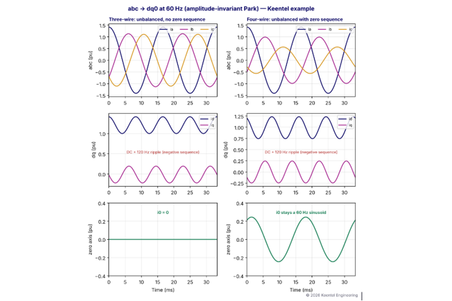
Figure 1. Keentel example at 60 Hz. Left: unbalanced three-wire currents give 120 Hz ripple in id and iq and zero i0. Right: four-wire unbalanced currents also produce a 60 Hz zero-axis current that remains sinusoidal after the Park transformation.
Zero-sequence control and negative-sequence control are different problems. Phase-current unbalance does not automatically mean zero-sequence current is present — and a zero-sequence current never becomes DC in the conventional Park frame.
Part B — Zero-Sequence Current in Park's Transformation: Why It Pulsates and How It Is Controlled — An Engineering Guide for US Inverter-Based Resources
1. Why this topic matters in the US
The US power system is rapidly shifting toward inverter-based generation and storage. Utility-scale solar, wind and battery plants connect at 34.5 kV collector systems and 115 kV to 500 kV points of interconnection. Distributed energy resources (DERs) connect to four-wire, multi-grounded distribution feeders at 12.47 kV, 13.2 kV, 24.9 kV and 34.5 kV, and behind-the-meter systems connect at 480Y/277 V and 208Y/120 V. Each of these environments treats zero-sequence current differently:
- Transmission-connected IBR plants are normally three-wire at the inverter terminals, so the inverters themselves cannot inject zero-sequence current. Zero-sequence behavior is set by the main power transformer and collector system grounding.
- Distribution-connected DERs sit on four-wire, multi-grounded feeders where zero-sequence current and ground-fault overvoltage are central to IEEE 1547-2018 interconnection requirements.
- Behind-the-meter and microgrid inverters often operate four-wire systems with single-phase loads, where neutral current is a real, continuous zero-sequence current that the inverter may need to supply or control, especially in island mode.
At the same time, IEEE 2800-2022 requires transmission-connected IBRs to inject negative-sequence current during unbalanced faults, and NERC PRC-029 requires them to ride through those faults. Understanding exactly how each sequence component behaves in the inverter's control frame is the foundation for meeting those requirements.
2. Symmetrical components: the phasor view
2.1 Fortescue's transformation
In 1918, C. L. Fortescue showed that any set of three unbalanced phasors can be expressed as the sum of three balanced sets. With the operator:
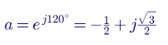
the sequence currents are:
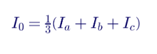
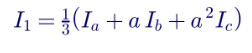
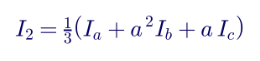
and the phase currents are recovered from:
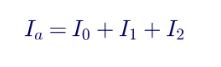
with Ib = I0 + a²I1 + aI2 and Ic = I0 + aI1 + a²I2.
2.2 Physical meaning of each sequence
| Sequence | Phase relationship | Physical behavior | Typical source |
|---|---|---|---|
| Positive (1) | Equal magnitude, 120° apart, a-b-c rotation | Produces forward-rotating field; carries useful power | Normal generation and load |
| Negative (2) | Equal magnitude, 120° apart, a-c-b rotation | Produces backward-rotating field; heats rotors, causes torque pulsation | Unbalanced loads, open phases, unbalanced faults |
| Zero (0) | Equal magnitude and in phase | Requires a return path through neutral or ground | Ground faults, single-phase loads in four-wire systems, grounded transformer windings |
Symmetrical components are defined for phasors, so they strictly apply to sinusoidal steady state at one frequency. Protective relays and short-circuit programs use them extensively: ground relays respond to 3I0, negative-sequence directional elements use V2 and I2, and generator protection (device 46) limits negative-sequence current to protect rotors.
2.3 Instantaneous symmetrical components
Control systems cannot wait for a phasor estimate over a full cycle. Engineers therefore use instantaneous quantities. The instantaneous zero-sequence component is exactly the same sum used for phasors, applied at each instant:
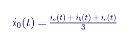
For a steady-state sinusoid, i0(t) is simply the time-domain waveform corresponding to the phasor I0. Instantaneous positive- and negative-sequence components are more involved, because separating them requires a 90° phase shift; this is why sequence-separation filters appear in inverter controls (Section 7).
3. The Clarke and Park transformations: the instantaneous view
3.1 Clarke (αβ0)
The Clarke transformation converts three phase quantities into two orthogonal stationary components and a zero component. In amplitude-invariant form:
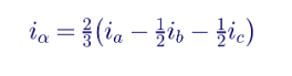
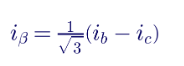
and i0 = (ia + ib + ic) ÷ 3, as above. In the stationary frame, balanced 60 Hz currents appear as 60 Hz sinusoids in α and β.
3.2 Park (dq0)
Park's transformation rotates the α and β components by the reference angle θ, normally the positive-sequence voltage angle from the phase-locked loop (PLL):


The zero-axis row is the same in Clarke and Park:
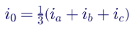
Notice that θ appears in the d and q rows only. The zero row has no dependence on angle — and that single fact explains why the zero-axis component never becomes DC.
3.3 Amplitude-invariant versus power-invariant scaling
| Convention | d and q scaling | Zero-axis definition | Power expression |
|---|---|---|---|
| Amplitude-invariant (common in controls) | 2/3 | i0 = (ia + ib + ic)/3 | p = (3/2)(vd id + vq iq) + 3 v0 i0 |
| Power-invariant (orthonormal) | √(2/3) | i0 = (ia + ib + ic)/√3 | p = vd id + vq iq + v0 i0 |
Both are correct; they simply scale differently. Mixing conventions between a simulation model, a vendor control description and a test procedure is a common source of factor-of-1.5 or factor-of-√3 errors. Every study and specification should state the convention explicitly. Sign conventions also vary: some texts align d with the voltage cosine, others use a q-axis-aligned convention, and some define iq with the opposite sign.
3.4 Instantaneous power with zero sequence
In the amplitude-invariant convention:

When both v0 and i0 are 60 Hz sinusoids, their product contains a DC term and a 120 Hz term. Zero-sequence power therefore adds both average power and a 120 Hz oscillation to the DC link of a four-wire converter one reason four-leg converters may need larger DC-link capacitance or active ripple control.
4. Why each sequence behaves differently in the dq0 frame
4.1 The space-vector view
Combining d and q into a complex space vector idq = id + j iq, and aligning the frame with the positive-sequence angle θ = ωt, the sequence components transform as:

where I1 and I2 are RMS magnitudes and φ1 and φ2 their phase angles (with amplitude-invariant scaling, the dq magnitude equals the phase peak value).
- Positive sequence rotates at +ω in the stationary frame. Rotating the frame at +ω cancels it, so it appears as a constant.
- Negative sequence rotates at −ω. Relative to a frame rotating at +ω, it rotates at −2ω, so it appears as a 120 Hz oscillation in both id and iq.
- Zero sequence has no rotating component at all. It is a common-mode signal identical on all phases, and the Park rotation does not act on it.
4.2 Why the zero axis "pulsates"
Calling i0 "pulsating" in the dq0 frame can be misleading. Nothing about the frame transformation creates the oscillation. A 60 Hz zero-sequence current is a 60 Hz signal in the abc frame, in the αβ0 frame and in the dq0 frame, because the zero axis is not rotated. In the dq0 frame, the d and q quantities become DC, so the zero axis stands out as the only component that remains at the fundamental frequency.
| Signal in phase quantities | In αβ (stationary) | In dq (positive synchronous frame) | In 0 axis |
|---|---|---|---|
| Balanced positive sequence at 60 Hz | 60 Hz | DC | 0 |
| Negative sequence at 60 Hz | 60 Hz | 120 Hz | 0 |
| Zero sequence at 60 Hz | 0 | 0 | 60 Hz |
| 5th harmonic (negative-sequence rotation) | 300 Hz | 360 Hz | 0 |
| 7th harmonic (positive-sequence rotation) | 420 Hz | 360 Hz | 0 |
| 3rd harmonic (zero-sequence in balanced systems) | 0 | 0 | 180 Hz |
| DC offset in one phase | DC | 60 Hz | DC |
The last rows matter in practice. Triplen harmonics from single-phase nonlinear loads in four-wire systems appear entirely in the zero axis, where they add in the neutral. A DC offset in one phase current, from a measurement error or transformer saturation, appears as 60 Hz ripple in d and q.
5. Worked example 1: unbalanced three-wire currents
A three-wire inverter sees phase currents (RMS, per unit on its rating):
| Phase | Magnitude (pu) | Angle |
|---|---|---|
| a | 1.00 | 0° |
| b | 0.80 | −130° |
| c | 0.78 | 128.4° (from Kirchhoff's current law: Ic = −Ia − Ib) |
Applying the sequence transformation:
| Component | Magnitude (pu) | Angle |
|---|---|---|
| I0 | 0.000 | — |
| I1 | 0.854 | −0.6° |
| I2 | 0.146 | 3.2° |
What the control system sees, using amplitude-invariant scaling (peak values):
- id and iq: a DC value of √2 × 0.854 = 1.21 pu (mostly on the d axis) with a 120 Hz ripple of amplitude √2 × 0.146 = 0.21 pu.
- i0: exactly zero at every instant, because the three line currents always sum to zero.
The phase currents are clearly unbalanced, yet there is no zero-sequence component. The unbalance is entirely negative sequence, and it is the 120 Hz ripple in id and iq that a negative-sequence controller must address.
6. Worked example 2: a four-wire 480Y/277 V inverter
A 250 kVA, 480Y/277 V four-wire battery inverter in a commercial microgrid supplies unbalanced single-phase loads in island mode. The phase currents are:
| Phase | Magnitude (pu) | Angle |
|---|---|---|
| a | 1.00 | 0° |
| b | 0.70 | −120° |
| c | 0.40 | 120° |
The base current is:

The sequence components are:
| Component | Magnitude (pu) | Magnitude (A) | Angle |
|---|---|---|---|
| I0 | 0.173 | 52 A | −30° |
| I1 | 0.700 | 211 A | 0° |
| I2 | 0.173 | 52 A | 30° |
The neutral carries the sum of the phase currents:

In the inverter's dq0 frame:
- id, iq: DC of about 0.99 pu peak with 120 Hz ripple of about 0.25 pu peak from the negative sequence.
- i0: a 60 Hz sinusoid of about 0.25 pu peak (√2 × 0.173).
A three-leg inverter with a split DC link, or a four-leg inverter, must supply that 60 Hz zero-axis current through its neutral path, and its control system must track a sinusoidal reference on the zero axis. The neutral conductor, the fourth leg and the DC-link capacitors must all be sized for the resulting duty, and the NEC's neutral conductor provisions apply to the facility wiring.
7. How negative-sequence current is controlled
Although the focus of this guide is zero sequence, it is essential to separate it clearly from negative-sequence control, because the two are often confused.
7.1 Why a single PI controller in the positive frame is not enough
A PI controller has infinite gain only at DC. In the positive synchronous frame, negative-sequence current appears at 120 Hz, where the PI controller's gain is finite. The controller cannot fully track or reject it, so unbalanced conditions produce residual negative-sequence current, DC-link voltage ripple at 120 Hz and active power oscillation.
7.2 Common solutions
| Method | How it works | Notes |
|---|---|---|
| Dual synchronous reference frame (DSRF) | Separate positive (+ω) and negative (−ω) rotating frames, each with PI controllers | Requires sequence separation by notch filters or decoupling (DDSRF) |
| Decoupled double synchronous reference frame (DDSRF) | Cancels cross-coupling between frames mathematically | Widely used for unbalanced grid PLLs and current control |
| Resonant controller at 120 Hz in the dq frame | Adds infinite gain at 2ω | Single frame, but must be tuned and discretized carefully |
| Proportional-resonant (PR) control in αβ | Resonant gain at 60 Hz tracks both sequences in the stationary frame | No Park transformation for current control |
| Sequence extraction with second-order generalized integrators (SOGI) | Generates in-phase and quadrature signals to separate sequences | Common in PLLs (DSOGI-PLL) |
7.3 Negative-sequence requirements in US standards
IEEE 2800-2022 requires transmission-connected IBRs to inject negative-sequence current during unbalanced faults, with a specified phase relationship to the negative-sequence voltage, so that negative-sequence directional elements and other protection relying on V2 and I2 operate correctly. Many legacy inverters suppressed negative-sequence current entirely, which confused protective relays. Meeting IEEE 2800 therefore requires deliberate negative-sequence control, not suppression. It does not ask the inverter to inject zero-sequence current; zero-sequence behavior at the point of interconnection is set by the plant's transformer connections and grounding.
8. How zero-sequence current is controlled
8.1 Three-wire converters: no zero-sequence path
Most utility-scale inverters are three-wire. With no neutral connection, Kirchhoff's current law forces:
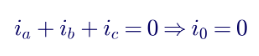
No zero-axis current controller is needed or useful, because the converter cannot create zero-sequence current. It can still produce a zero-sequence (common-mode) voltage, which is widely exploited in pulse-width modulation: adding a common-mode voltage, such as third-harmonic injection or space-vector modulation, extends the linear modulation range by about 15% without affecting line currents. That common-mode voltage does, however, appear across stray capacitances and can drive leakage currents, which is why PV inverters and transformer designs must manage it.
8.2 Four-wire topologies
Converters that can carry zero-sequence current include:
| Topology | Zero-sequence path | Typical application |
|---|---|---|
| Three-leg with split DC-link capacitor | Neutral connected to the DC-link midpoint | Smaller UPS and microgrid inverters |
| Four-leg converter | Dedicated fourth leg connected to neutral | Microgrid inverters, active power filters, grid-forming storage |
| Three single-phase inverters (or H-bridges) | Each phase independent with common neutral | Some commercial and residential systems |
| Converter with a grounding (zigzag) transformer | Transformer provides zero-sequence path | Islanded microgrids with three-wire inverters |
8.3 The zero-axis plant
For a four-leg converter with phase filter inductance L and neutral inductance Ln, the zero-axis dynamics are:

where v0 is the converter's zero-sequence output voltage and e0 is the grid or load zero-sequence voltage. The factor of 3 appears because the neutral carries 3i0. The zero-axis plant is a first-order system just like each phase, but it must be controlled with an AC reference.
8.4 Why PI control is not sufficient
The internal model principle states that a controller tracks a signal with zero steady-state error only if it contains a model of that signal. A PI controller contains an integrator — the model of a constant. For a 60 Hz zero-axis reference, the PI controller's gain at 60 Hz is finite:
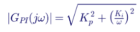
so a steady-state magnitude and phase error remains. Increasing the PI gains reduces the error but also reduces stability margins, especially with PWM and sampling delays.
8.5 Proportional-resonant control
A resonant term provides very high gain at the target frequency ω0 = 2π × 60 rad/s. A practical, non-ideal PR controller is:

where Kr sets the resonant gain and ωc sets the bandwidth of the resonance, typically a few radians per second, to tolerate small frequency deviations. Additional resonant terms at 180 Hz (3rd harmonic) and 300 Hz (5th harmonic) can be added for harmonic compensation in four-wire systems with nonlinear loads.
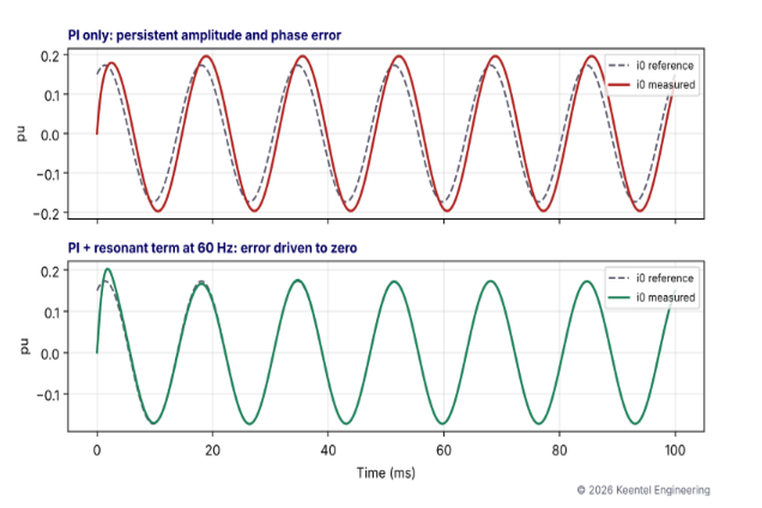
Figure 2. Keentel simulation of a four-wire zero-axis current loop tracking a 0.173 pu, 60 Hz reference with a 60 Hz zero-sequence voltage disturbance. With PI control only, a peak error of about 0.06 pu (about 35% of the reference) remains. With an added resonant term at 60 Hz, the error falls below 0.001 pu within about two cycles.
8.6 Other approaches
| Approach | Description | Considerations |
|---|---|---|
| Stationary-frame control | Control i0 directly with PR or repetitive controllers, without Park transformation | Natural fit, because the zero axis is never rotated |
| Frequency-synchronized transformation (demodulation) | Create a fictitious orthogonal signal (by a quarter-cycle delay or SOGI), form a single-phase dq frame for i0 and use PI controllers on the resulting DC values | Allows familiar PI tuning; adds filter dynamics |
| Repetitive control | Internal model of a periodic signal and all its harmonics | Excellent harmonic rejection; slower dynamics; sensitive to frequency variation |
| Dedicated zero-sequence voltage control (grid-forming) | Regulate v0 at the point of connection to zero, letting the load draw the zero-sequence current it needs | Common for islanded four-wire grid-forming inverters |
| Deadbeat or model predictive control | Direct calculation of the voltage that achieves the reference next sample | Fast; sensitive to model accuracy and delays |
8.7 Frequency adaptation and discretization
US grid frequency is tightly controlled, but islanded microgrids can operate several tenths of a hertz from 60 Hz. Resonant controllers should take their resonant frequency from the PLL so the peak moves with system frequency. Discretization also matters: the resonant term should be implemented with methods that preserve the exact resonant frequency, such as Tustin with prewarping or impulse-invariant forms, and computation and PWM delays should be compensated so the resonant terms do not destabilize the loop at higher harmonics.
9. Ground faults: what the controller can and cannot do
9.1 The zero-sequence path is in the network
During a single-line-to-ground fault, zero-sequence current flows only where the network provides a path: grounded transformer neutrals, grounding transformers, grounded generators and shunt capacitance. A three-wire inverter connected through a delta or ungrounded-wye winding contributes no zero-sequence current, no matter what its zero-axis reference is. Even a four-wire converter cannot cancel zero-sequence fault current supplied by a grounded transformer elsewhere in the network; the fault current is driven by the grid's zero-sequence voltage through the network's zero-sequence impedance.
The controller's ability to influence zero-sequence current depends on:
- Converter topology: whether it has a zero-sequence path at all.
- Available voltage: whether the DC link can produce the zero-sequence voltage needed to drive or block current.
- Current limits: the converter's total phase current limit, shared among positive, negative and zero sequence.
- Protection requirements: ground relays depend on zero-sequence current; suppressing it could compromise fault detection.
9.2 Worked example 3: SLG fault on a 34.5 kV collector
A 100 MW solar plant connects through a 138 kV grounded-wye / 34.5 kV delta main power transformer. A zigzag grounding transformer establishes the 34.5 kV system ground. Inverters connect through 34.5 kV delta / 630 V wye-ungrounded pad-mount transformers. On a 100 MVA base at 34.5 kV (base current 1,673 A):
| Parameter | Value |
|---|---|
| Positive- and negative-sequence impedance at the 34.5 kV bus (grid through MPT) | j0.12 pu |
| Zero-sequence impedance (grounding transformer only; the MPT delta blocks grid zero sequence) | j0.30 pu |
| Inverter zero-sequence contribution | None (three-wire, isolated by delta and ungrounded windings) |
The SLG fault current from the network sources is:

All of the zero-sequence current — 3I0 = 9.3 kA in the grounding transformer neutral — comes from the grounding transformer. The inverters add limited positive- and negative-sequence current under IEEE 2800 control, but zero zero-sequence current. Their zero-axis "reference" is irrelevant to the ground fault.
The grounding design must also satisfy effective grounding to control overvoltage on the unfaulted phases:
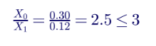
Effective grounding at the collector bus limits temporary overvoltage on unfaulted phases during the fault, protecting surge arresters and equipment. The analysis must also consider the case where the plant is separated from the grid with inverters still energizing the collector — the condition where effective grounding by the grounding transformer becomes critical.
9.3 Distribution-connected DERs and ground-fault overvoltage
On US four-wire multi-grounded distribution systems, a DER connected through a delta or ungrounded winding can energize an islanded feeder section without a ground reference. During a ground fault, unfaulted-phase voltages can rise toward line-to-line values, stressing customer equipment and arresters. IEEE 1547-2018 addresses temporary overvoltage limits, and utilities set grounding requirements — often requiring effective grounding through the interconnection transformer or a grounding transformer, or relying on fast inverter trip and inverter-limited overvoltage behavior verified by testing. These decisions are fundamentally about zero-sequence paths.
10. Phase-locked loops under unbalance
The PLL defines the Park angle θ. Under unbalanced voltages, a conventional synchronous reference frame PLL sees negative-sequence voltage as a 120 Hz ripple in vq, which introduces 120 Hz oscillation in its frequency and angle estimates. Zero-sequence voltage does not affect a PLL based on the d and q axes, because it is removed by the transformation, but it does affect PLLs or measurements based directly on single-phase voltages.
| PLL type | Behavior under unbalance |
|---|---|
| Synchronous reference frame (SRF) PLL | 120 Hz ripple in angle and frequency unless bandwidth is low |
| Decoupled double SRF (DDSRF) PLL | Separates positive and negative sequences; accurate angle |
| Dual SOGI (DSOGI) PLL | Extracts sequence components in the stationary frame; robust |
| Moving-average-filter PLL | Rejects 120 Hz ripple; adds delay |
Accurate sequence detection is especially important for IEEE 2800 fault response, because positive- and negative-sequence current injection must be calculated from correctly separated sequence voltages within a fraction of a cycle.
11. Modeling and study implications
11.1 Positive-sequence RMS studies
Positive-sequence programs such as PSS®E and PSLF represent only positive-sequence quantities during time-domain simulation. Unbalanced faults are represented by connecting an equivalent fault shunt derived from negative- and zero-sequence networks. IBR negative-sequence current injection and zero-sequence network behavior are only approximated.
11.2 Short-circuit studies
Short-circuit programs model IBRs as controlled current sources or with vendor-provided fault current tables, including negative-sequence behavior. Zero-sequence networks must accurately represent transformer winding connections, grounding transformers and neutral impedances. Errors here directly affect ground relay settings and equipment ratings.
11.3 EMT studies
EMT tools such as PSCAD simulate instantaneous three-phase waveforms with the vendor's actual control code, capturing dq0 behavior, sequence separation, PLL response and current limiting during unbalanced faults. Transmission providers increasingly require EMT models to verify IEEE 2800 negative-sequence injection and ride-through.
| Study | Zero-sequence considerations |
|---|---|
| Short circuit and protection coordination | Grounding transformer sizing, ground relay settings, effective grounding |
| Temporary overvoltage and insulation coordination | Unfaulted-phase voltage during ground faults and island conditions |
| EMT ride-through studies | Negative-sequence injection, sequence detection, current limit allocation |
| Harmonic studies | Triplen harmonics in four-wire systems; zero-sequence resonance with cable capacitance |
| Microgrid studies | Neutral current, four-leg inverter control, unbalanced island operation |
12. Current limit allocation during unbalanced faults
Inverter semiconductor ratings limit peak phase current, not sequence current. With positive-, negative- and (in four-wire systems) zero-sequence currents present, the peak in the worst phase is approximately:
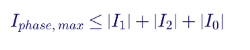
The exact peak depends on relative angles, but the sum is a conservative bound. Control systems must allocate the available current: IEEE 2800 sets priorities for reactive and negative-sequence current during faults, and a four-wire grid-forming inverter must also reserve capacity for zero-sequence current. Keentel's studies check that the allocation keeps every phase within its limit for the worst fault types and angles, rather than limiting the magnitude of a single dq vector.
13. Practical design guidance
- State the transformation convention. Amplitude- or power-invariant scaling, d- or q-axis alignment and sign conventions should be explicit in every model and specification.
- Identify the zero-sequence path first. Determine whether the converter, its transformer and the network provide a zero-sequence path before designing any zero-axis control.
- Do not apply a DC PI controller to a 60 Hz signal. Use resonant, stationary-frame or demodulation methods for the zero axis.
- Separate negative- and zero-sequence functions. They have different frequencies in the dq0 frame, different physical paths and different standards requirements.
- Size the neutral and DC link for zero-sequence duty. Neutral current is 3i0, and zero-sequence power adds 120 Hz ripple on the DC link.
- Design grounding deliberately. Grounding transformers and interconnection transformer connections determine zero-sequence fault current and temporary overvoltage.
- Verify with EMT simulation and testing. Confirm sequence detection, current allocation and fault response with the actual control code.
14. Large-load and data center applications
Data centers and other large loads increasingly use inverter-based UPS systems, battery storage and on-site generation operating as microgrids at 480 V and medium voltage. Four-wire 480Y/277 V distribution, single-phase IT loads and triplen harmonics create zero-sequence current that grid-forming UPS and storage inverters must supply when the facility is islanded. Neutral conductors, grounding transformers, ground-fault protection under NEC Article 230.95 and 240.13 provisions and selective coordination all depend on correct zero-sequence analysis.
15. Transformer connections and the zero-sequence network
Because inverters are usually three-wire, the zero-sequence behavior of an IBR plant, a substation or a distribution interconnection is set almost entirely by transformer winding connections and grounding. Engineers draw the zero-sequence network for every study, and a single misread winding connection can change ground fault current by an order of magnitude.
| Transformer connection | Zero-sequence behavior | Typical US application |
|---|---|---|
| Grounded wye – grounded wye | Passes zero-sequence current between both sides (through the transformer impedance) | Distribution substation transformers in some utilities; interconnection transformers on multi-grounded feeders |
| Grounded wye – delta | Provides a zero-sequence source on the grounded-wye side; blocks zero-sequence from passing through; the delta circulates zero-sequence current internally | Main power transformers, generator step-up transformers, many IBR interconnection transformers |
| Delta – grounded wye | Same as above, with the zero-sequence source on the low-voltage side | Distribution substation transformers (for example, 138 kV delta / 13.8 kV grounded wye) |
| Ungrounded wye – delta or delta – delta | No zero-sequence path on either side | Some industrial and inverter step-up transformers |
| Grounded wye – ungrounded wye | No zero-sequence current path through the transformer | Some pad-mount inverter transformers |
| Zigzag (grounding transformer) | Low zero-sequence impedance, high positive-sequence impedance; provides a ground reference only | Collector systems fed by delta windings; islanded microgrids |
| Autotransformer with delta tertiary | Zero-sequence path on both voltage levels; tertiary circulates zero-sequence current | 345/138 kV and 500/230 kV transmission substations |
Two practical details often cause errors:
- Three-legged core-form transformers have a zero-sequence impedance noticeably lower than the positive-sequence value even without a delta winding, because zero-sequence flux must return through the tank, which acts like a high-impedance delta.
- Pad-mount transformer connections at solar and wind plants vary by manufacturer and utility preference. Grounded-wye primaries on dozens of pad-mounts collectively create a strong zero-sequence source on the collector system, changing ground fault current and relay sensitivity.
16. Worked example 4: designing a zero-axis PR controller
Consider the zero-axis current loop of the 250 kVA, 480Y/277 V four-leg inverter from Section 6.
| Parameter | Value |
|---|---|
| Base impedance | 480² ÷ 250,000 = 0.922 Ω |
| Phase filter reactance | 0.10 pu |
| Neutral leg reactance | 0.05 pu |
| Zero-sequence reactance X0 = X + 3Xn | 0.25 pu = 0.230 Ω, or L0 = 611 μH |
| Zero-sequence resistance | 0.01 pu |
| Target current loop bandwidth | 500 Hz |
Step 1: PI design
A standard design places the loop crossover at the target bandwidth:

with the integral zero at 50 rad/s, giving Ki = 96 Ω/s. At 60 Hz, the PI gain is about 1.94 Ω and the loop gain with the zero-sequence plant gives a steady-state tracking error of about 12% in magnitude, with a phase error — unacceptable for neutral current control or zero-sequence voltage regulation.
Step 2: add a resonant term
Adding a non-ideal resonant term with Kr = 200 Ω and ωc = 5 rad/s raises the controller gain at exactly 60 Hz to about 202 Ω. The steady-state tracking error falls to about 0.1%. The narrow resonance barely affects the crossover region, so stability margins set by the PI design are preserved.
Step 3: practical checks
- Frequency adaptation: in island mode, take ω0 from the PLL or grid-forming frequency reference.
- Delay compensation: account for one to one-and-a-half sample periods of computation and PWM delay, which shift the phase of the resonant path; a phase-lead compensation term is often added.
- Harmonic resonators: add 180 Hz and 300 Hz resonant terms only if the loop phase margin at those frequencies remains positive.
- Anti-windup: limit the resonant integrator states when the converter reaches its voltage or current limit.
- Discretization: implement the resonant term with a method that preserves its exact frequency at the controller's sampling rate.
Figure 2 in Section 8.5 shows the same contrast in the time domain: a persistent error with PI alone, and near-perfect tracking once the resonant term is added.
17. Sequence quantities in protection and metering
Zero-sequence current is central to ground fault protection, so it is worth connecting the control-system view to the relay engineer's view.
| Measurement | How it is obtained | Typical protection use |
|---|---|---|
| Residual current 3I0 | Sum of three phase CT secondaries (residual connection) or calculated in a numerical relay | Ground overcurrent (50N/51N), ground directional (67N), ground distance |
| Neutral current | CT in the transformer or generator neutral | Transformer ground backup (51G), restricted earth fault (87N) |
| Zero-sequence voltage 3V0 | Broken-delta VT connection or calculated from phase voltages | Ground directional polarizing, ground fault detection on ungrounded systems (59N) |
| Negative-sequence current I2 | Calculated in numerical relays | Negative-sequence directional (67Q), generator unbalance (46), open-phase detection |
At IBR plants, the absence of inverter zero-sequence current has a direct consequence: ground relays near the plant see zero-sequence current only from the main power transformer or grounding transformer. If that source is removed or changed, ground relays may lose sensitivity. Conversely, IEEE 2800-compliant negative-sequence injection restores the reliability of negative-sequence directional elements that legacy inverters could defeat. Relay settings and the plant's grounding design must therefore be developed together.
18. Testing and commissioning
Sequence-component behavior should be verified before and after energization:
- Phase rotation and polarity checks: a wrong phase sequence turns positive sequence into negative sequence in the inverter's controls.
- Hardware-in-the-loop (HIL) testing: the actual controller is tested against a real-time simulation of unbalanced faults, open phases and four-wire unbalance.
- Factory and type tests: IEEE 2800.2 and IEEE 1547.1 procedures verify ride-through and fault current behavior, including negative-sequence response for transmission-connected IBRs.
- Staged field tests: where practical, controlled unbalance or single-phase load tests confirm four-wire inverter neutral control.
- Event analysis: high-resolution plant and relay records from real faults validate sequence injection and update EMT and short-circuit models.
19. Common misconceptions
| Misconception | Reality |
|---|---|
| Unbalanced currents always contain zero sequence | Three-wire unbalance is negative sequence only |
| Park's transformation turns all fundamental-frequency quantities into DC | Only the positive sequence aligned with the frame becomes DC; negative sequence becomes 2ω and zero sequence stays at ω |
| The zero axis "pulsates" because of the frame rotation | The zero axis is not rotated at all; it simply remains the original 60 Hz signal |
| A zero-axis reference of zero eliminates ground fault current | Ground fault current is supplied by network zero-sequence sources the inverter does not control |
| Suppressing negative-sequence current is the safest fault response | IEEE 2800 requires controlled negative-sequence injection to support protection |
| A larger PI gain will remove the zero-axis tracking error | It reduces the error but cannot eliminate it, and erodes stability margins |
| Zero-sequence voltage from modulation is harmless | It drives common-mode currents through stray capacitance and must be managed |
20. Grid-forming inverters under unbalance
Grid-forming inverters behave as controlled voltage sources rather than current sources. That changes how unbalance is handled:
- Voltage-source behavior: a grid-forming inverter tries to hold a balanced internal voltage. Unbalanced loads then draw negative-sequence (and, in four-wire systems, zero-sequence) current naturally, as they would from a synchronous machine.
- Negative-sequence impedance: many grid-forming designs emulate a low negative-sequence impedance so they help balance local voltage. That improves power quality but increases negative-sequence current and can reach current limits during unbalanced faults.
- Current limiting: when a fault drives current above rating, the inverter must limit current without losing synchronism. Limiting strategies that treat sequences separately behave very differently from those that limit the total phase current.
- Four-wire island operation: grid-forming storage and UPS inverters serving 480Y/277 V or 208Y/120 V loads must regulate zero-sequence voltage so the neutral-to-ground and phase-to-neutral voltages stay balanced, using the resonant or stationary-frame techniques described in Section 8.
As US ISOs and transmission owners begin to define grid-forming performance requirements, sequence-component behavior during unbalanced faults is one of the key topics in specification and model validation.
21. Open-phase conditions
An open conductor, a single blown fuse or a broken jumper is a series unbalance rather than a shunt fault. It produces significant negative-sequence current, and in grounded systems zero-sequence current, without the high current magnitudes that ordinary protection detects.
| Effect | Consequence |
|---|---|
| Negative-sequence current from loads and inverters | Rotor heating in nearby generators and motors; 120 Hz DC-link ripple in inverters |
| Zero-sequence current in grounded transformer neutrals | Possible ground relay operation or, worse, undetected sustained unbalance |
| Voltage unbalance at the inverter terminals | PLL ripple, current control saturation, possible inverter trips |
| Transformer behavior | Three-legged core-form units can partially regenerate the missing phase voltage, masking the condition |
After several nuclear plant events caused by open phases in offsite power circuits, US nuclear plants implemented dedicated open-phase detection systems. For IBR plants and industrial facilities, open-phase conditions are assessed with sequence-component analysis and EMT simulation, and negative-sequence protection (46 and 47 elements) or dedicated open-phase detection may be specified.
22. Measuring i0 in real time: sensor and offset pitfalls
Because i0 is the small difference left after adding three large phase currents, it is very sensitive to measurement errors. In a three-wire converter, the calculated i0 should be exactly zero, yet controllers often see a non-zero value:
- Sensor gain mismatch: a 1% gain difference between phase current sensors produces an apparent i0 of about 0.33% of rated current at 60 Hz, even when the true zero-sequence current is zero.
- DC offsets: an analog-to-digital converter or Hall-sensor offset in one phase appears as a DC component in i0 and as 60 Hz ripple in id and iq.
- Sampling skew: sampling phases at slightly different instants creates a fundamental-frequency error proportional to the timing difference.
- Common-mode noise: PWM switching produces high-frequency common-mode currents through stray capacitance that appear in the summed measurement.
Good practice is to:
- Calibrate gains and offsets of every current channel during commissioning and, where possible, continuously estimate offsets in operation.
- Measure neutral current directly in four-wire systems rather than relying only on the sum of phase measurements.
- Filter appropriately, removing switching-frequency content without adding excessive delay to the zero-axis control loop.
- Avoid controlling noise: in three-wire converters, do not close a control loop on a calculated i0 that can only contain measurement error.
- Use relay-grade measurements for protection, keeping protection functions independent of the converter's control measurements.
23. How Keentel Engineering helps
Keentel Engineering provides inverter-based resource, protection and power system studies for developers, utilities, industrial facilities and data centers, from 4 kV to 765 kV.
| Stage | Keentel scope | Outcome |
|---|---|---|
| Grounding and short-circuit studies | Zero-sequence network modeling, grounding transformer sizing, effective grounding and TOV analysis | Safe, compliant grounding designs |
| IEEE 2800 and IEEE 1547 assessments | Negative-sequence injection, ride-through and DER interconnection evaluations | Plants that meet US interconnection requirements |
| EMT studies | PSCAD studies of unbalanced faults, sequence detection, PLL performance and current limits | Verified dynamic performance with vendor models |
| Protection and coordination | Ground relay settings, negative-sequence directional elements and coordination with IBR fault behavior | Reliable fault detection |
| Microgrid and four-wire system design | Four-leg and grid-forming inverter applications, neutral sizing and unbalanced load studies | Stable, balanced island operation |
| Owner's engineer | Review of inverter control descriptions, model conventions and test results | Specifications and models that match reality |
Why clients choose Keentel Engineering
- Control-aware power system engineering: we understand both the network and the inverter control system that interacts with it.
- Protection and grounding depth: zero-sequence analysis is at the heart of ground relay settings, grounding design and overvoltage protection.
- Standards fluency: IEEE 2800, IEEE 1547, NERC PRC-029 and utility interconnection requirements.
- EMT capability: detailed PSCAD modeling to confirm what simplified models cannot.
- Licensed professional engineering: a Florida-registered firm with offices in Tampa, Austin, Sacramento and Baltimore, supporting projects nationwide.
Need help with IBR fault response, grounding design or four-wire inverter control? Talk to Keentel Engineering at (813) 389-7871, contact@keentelengineering.com, or book a 15-minute scoping call at calendly.com/keentel-engineering/15min.
Part C — Case Studies
The following are illustrative scenarios based on conditions typical of US IBR, distribution and microgrid projects. They show how Keentel Engineering approaches sequence-component and zero-sequence problems; site details are generalised and figures are rounded.
Case Study 1 — 200 MW battery plant at 230 kV: negative-sequence injection and relay misoperation risk
Situation. A 200 MW battery storage plant connects at 230 kV. During EMT studies for interconnection, the transmission owner's protection engineers raise concern that the plant's legacy inverter firmware suppresses negative-sequence current during unbalanced faults.
Analysis. Keentel's PSCAD study with the vendor model confirms that, for line-to-ground and line-to-line faults on the 230 kV line, the plant injects balanced positive-sequence current only. Negative-sequence directional elements at the remote terminal see too little I2 to operate reliably, and the plant would not meet IEEE 2800 negative-sequence requirements. The studies also show that zero-sequence current at the POI is set entirely by the main power transformer's grounded-wye winding, independent of inverter controls.
Engineered solution. Working with the inverter manufacturer, Keentel evaluates an IEEE 2800-compliant firmware option that controls positive- and negative-sequence current separately using a decoupled dual-frame controller, with current limits allocated per phase. Relay settings at both line terminals are reviewed with the new fault current characteristics.
Outcome. The plant meets IEEE 2800 negative-sequence injection requirements in EMT simulation, the line's negative-sequence directional elements operate reliably, and the transmission owner accepts the updated model and settings.
Case Study 2 — 12.47 kV distribution feeder: DER ground-fault overvoltage
Situation. A 5 MW solar plant connects to a 12.47 kV four-wire multi-grounded distribution feeder through a 12.47 kV delta / 480 V wye transformer. The utility is concerned about overvoltage if the feeder breaker opens for a ground fault while the plant continues to energize the feeder.
Analysis. Keentel's study shows that, with a delta high-voltage winding, the plant provides no zero-sequence path on the feeder. If islanded during a ground fault, unfaulted-phase voltages could rise well above the levels connected customer equipment can tolerate, unless the inverters trip quickly enough or limit overvoltage themselves. Keentel evaluates the inverters' certified ground-fault overvoltage behavior and the timing of utility protection.
Engineered solution. Keentel compares options: a grounded-wye/delta interconnection transformer providing effective grounding, a separate grounding transformer, or reliance on certified inverter overvoltage limiting with fast trip. A grounding transformer sized for effective grounding without excessive ground current desensitization of the utility's feeder relays is selected, and the utility's ground relay settings are verified.
Outcome. Temporary overvoltage stays within acceptable limits for all studied conditions, feeder ground protection remains sensitive, and the interconnection is approved.
Case Study 3 — data center microgrid at 480Y/277 V: four-leg inverter neutral control
Situation. A data center campus uses grid-forming battery inverters to carry 480Y/277 V critical distribution through utility outages. In island-mode testing, unbalanced single-phase loads and triplen harmonics from IT power supplies cause voltage unbalance and neutral current that a three-leg inverter design cannot handle.
Analysis. Keentel's study quantifies zero-sequence current from single-phase load unbalance and third-harmonic current from IT loads. The analysis shows that the original three-wire design relies on a small zigzag transformer that would overheat, and that the inverter's zero-axis control (where available) used a PI controller unable to track 60 Hz and 180 Hz zero-sequence components.
Engineered solution. Keentel specifies four-leg grid-forming inverters with proportional-resonant zero-sequence voltage control at 60 Hz and 180 Hz, a neutral conductor sized for harmonic neutral current, and revised ground-fault protection coordination. EMT simulations verify voltage balance and current sharing.
Outcome. Island-mode voltage unbalance falls within design limits, the neutral and inverter fourth leg operate within ratings, and the campus passes its integrated systems test.
Part D — Technical FAQ: Zero-Sequence Current and the dq0 Frame
It is the component of three-phase current that is equal in magnitude and in phase on all three phases. It equals one-third of the sum of the phase currents and can flow only where there is a return path through a neutral or ground.
In the amplitude-invariant transformation, i0 = (ia + ib + ic) ÷ 3. In the power-invariant form, the divisor is √3. It is the instantaneous zero-sequence current.
The zero axis is calculated from the plain sum of phase currents and does not depend on the rotation angle. Park's rotation acts only on the d and q axes, so a 60 Hz zero-sequence current remains a 60 Hz sinusoid.
In a frame rotating with the positive sequence, negative-sequence current appears as a 120 Hz oscillation in id and iq in a 60 Hz system.
No. In a three-wire system, line currents always sum to zero, so the zero-sequence component is zero. The unbalance appears entirely as negative sequence.
No. Without a neutral or ground path, it cannot create zero-sequence current, so no zero-axis current controller is needed. It can still produce zero-sequence voltage, which is used in modulation.
Three-leg converters with a split DC link and neutral connection, four-leg converters, three single-phase converters with a common neutral, and converters paired with grounding transformers.
A PI controller has infinite gain only at DC. The zero-axis current is a 60 Hz signal, so the PI controller leaves a steady-state magnitude and phase error.
It is a controller with a resonant term that provides very high gain at a chosen frequency, such as 60 Hz. It tracks sinusoidal references and rejects sinusoidal disturbances at that frequency with near-zero steady-state error.
Stationary-frame control, single-phase dq transformation using a quarter-cycle delay or SOGI, repetitive control, deadbeat or model predictive control, and zero-sequence voltage control in grid-forming inverters.
The neutral current equals three times the zero-sequence current: IN = 3I0.
Not by itself. Zero-sequence fault current is supplied by grounded transformers and other network paths. A three-wire inverter contributes none, and even a four-wire converter cannot cancel current supplied elsewhere in the network.
The main power transformer winding connections, grounding transformers, pad-mount transformer connections, neutral impedances and the network's zero-sequence impedance.
No. IEEE 2800-2022 requires negative-sequence current injection during unbalanced faults. Zero-sequence behavior at the point of interconnection is determined mainly by the plant's transformer and grounding design.
A system is effectively grounded at a location when X0/X1 is 3 or less and R0/X1 is 1 or less. It limits overvoltage on unfaulted phases during ground faults.
If a DER without a zero-sequence path energizes an islanded section of a four-wire multi-grounded feeder during a ground fault, unfaulted-phase voltages can rise significantly, stressing equipment. Grounding or fast, certified overvoltage behavior is needed.
A conventional synchronous reference frame PLL sees negative-sequence voltage as 120 Hz ripple, causing oscillation in its angle and frequency estimates. Sequence-separating PLLs such as DDSRF or DSOGI PLLs solve this.
In balanced systems, third, ninth and other triplen harmonics are in phase on all three phases, so they behave as zero sequence and add in the neutral.
Semiconductor ratings limit phase current. With multiple sequence components, the worst-phase peak can approach the sum of the sequence magnitudes, so controls must allocate current to keep every phase within its limit.
Assuming that phase unbalance means zero-sequence current, or applying DC-frame controllers to signals that remain AC in the dq0 frame. Correct analysis starts with the converter topology and the network's zero-sequence path.
References and Further Reading
Links were current at publication (October 2026).
- C. L. Fortescue, Method of Symmetrical Co-ordinates Applied to the Solution of Polyphase Networks. Transactions of the AIEE, 1918.
- R. H. Park, Two-Reaction Theory of Synchronous Machines. Transactions of the AIEE, 1929.
- IEEE Std 2800-2022, Standard for Interconnection and Interoperability of Inverter-Based Resources Interconnecting with Associated Transmission Electric Power Systems. IEEE.
- IEEE Std 1547-2018, Standard for Interconnection and Interoperability of Distributed Energy Resources with Associated Electric Power Systems Interfaces. IEEE.
- IEEE Std C62.92 series, Guide for the Application of Neutral Grounding in Electrical Utility Systems. IEEE.
- NERC Reliability Standard PRC-029, Frequency and Voltage Ride-through Requirements for Inverter-Based Resources. North American Electric Reliability Corporation.
- NFPA 70, National Electrical Code. National Fire Protection Association.
- R. Teodorescu, M. Liserre and P. Rodríguez, Grid Converters for Photovoltaic and Wind Power Systems. Wiley-IEEE Press.
Disclaimer
This article is general technical information for educational purposes. It is not engineering advice for any specific project and does not create a professional relationship. Numerical examples and simulations use Keentel Engineering's simplified models with illustrative parameters; actual inverter behavior depends on the manufacturer's control implementation, firmware and hardware. Grounding, protection and interconnection designs must follow current standards, utility and transmission provider requirements and project-specific engineering analysis, sealed by a licensed professional engineer where required.
Case studies are illustrative scenarios based on typical project conditions, not records of specific client projects. Figures are rounded and indicative.
IEEE, NERC, NFPA, PSS®E, PSLF, PSCAD™ and other names are the property of their respective owners. Keentel Engineering is not affiliated with or endorsed by these organisations or any software or equipment vendor.
| Office | Address | Phone |
|---|---|---|
| Head Office — Tampa | 400 N Ashley Dr STE #2600, Tampa FL 33602 | (813) 389-7871 |
| Austin | 5900 Balcones Drive STE 100, Austin TX 78731 | (512) 591-0752 |
| Sacramento | 1401 21st St Ste R, Sacramento CA 95811 | (916) 913-4524 |
| Baltimore | 306 W Redwood St STE 200, Baltimore MD 21201 | (410) 225-2181 |
contact@keentelengineering.com · keentelengineering.com · calendly.com/keentel-engineering/15min
State of Florida — Registry No. 36853, KEENTEL LLC, DBA: KEENTEL ENGINEERING
Copyright 1995–2026 Keentel Engineering. All Rights Reserved.

About the Author:
Sandip "Sonny" R. Patel, P.E.
IEEE Senior Member · Founder & CEO, Keentel Engineering
In 1995, Sonny Patel earned his Electrical Engineering degree from the University of Illinois. But degrees don't build legacies — action does.
For three decades, he has worked the power industry from every side of the table: 16 years as a utility engineer at Exelon/Commonwealth Edison; generation leadership across hydroelectric, industrial steam turbine, and a 9 GW renewable fleet; NERC Regional Entity Senior Compliance Engineer and Audit Team Lead, auditing some of the nation's largest utilities; and testing and commissioning lead on equipment up to 765 kV — the very top of the North American grid.Utility. Generator. Regulator. Consultant. Few engineers have seen all four seats. Fewer still have sat in them.
His experience spans nuclear, hydro, conventional generation, renewables, oil and gas, mining — and today's data centers, where he is authoring a three-book series on data center design. He is a Licensed Professional Engineer in six states and a Licensed Electrical Contractor in Florida (Unlimited EC) — he doesn't just design the work; he's qualified to stand behind its execution.Today, as Founder and CEO of Keentel Engineering, Sonny leads a nationwide team of engineers delivering substation design, power system studies, NERC compliance, and commissioning — done right, coast to coast.Three decades. Every side of the table. One standard: accountable engineering.
Services

Let's Discuss Your Project
Let's book a call to discuss your electrical engineering project that we can help you with.
About the Author:
Sandip "Sonny" R. Patel, P.E.
IEEE Senior Member · Founder & CEO, Keentel Engineering
In 1995, Sonny Patel earned his Electrical Engineering degree from the University of Illinois. But degrees don't build legacies — action does.
For three decades, he has worked the power industry from every side of the table: 16 years as a utility engineer at Exelon/Commonwealth Edison; generation leadership across hydroelectric, industrial steam turbine, and a 9 GW renewable fleet; NERC Regional Entity Senior Compliance Engineer and Audit Team Lead, auditing some of the nation's largest utilities; and testing and commissioning lead on equipment up to 765 kV — the very top of the North American grid.
Utility. Generator. Regulator. Consultant. Few engineers have seen all four seats. Fewer still have sat in them.
His experience spans nuclear, hydro, conventional generation, renewables, oil and gas, mining — and today's data centers, where he is authoring a three-book series on data center design. He is a Licensed Professional Engineer in six states and a Licensed Electrical Contractor in Florida (Unlimited EC) — he doesn't just design the work; he's qualified to stand behind its execution.
Today, as Founder and CEO of Keentel Engineering, Sonny leads a nationwide team of engineers delivering substation design, power system studies, NERC compliance, and commissioning — done right, coast to coast.Three decades. Every side of the table. One standard: accountable engineering.
Leave a Comment
Thank you for contacting us.
We will get back to you as soon as possible.
We will get back to you as soon as possible.
Oops, there was an error sending your message.
Please try again later.
Please try again later.
Related Posts

By SANDIP R PATEL
•
October 11, 2026
Learn which fault produces the highest current at a bus, why SLG faults can exceed three-phase faults, and how symmetrical components determine fault duty.

By SANDIP R PATEL
•
October 11, 2026
Explore grid inertia, RoCoF and frequency response, with swing equation calculations, frequency nadir analysis and US power system simulation examples.

By SANDIP R PATEL
•
October 11, 2026
Learn transient stability analysis, swing equation, equal-area criterion and critical clearing time with a 345 kV worked example and NERC TPL-001 guidance.

By SANDIP R PATEL
•
October 11, 2026
Learn why inverter controls become unstable in weak grids, how PLL bandwidth and SCR affect stability, and how PSCAD EMT studies identify and mitigate oscillations.

By SANDIP R PATEL
•
October 11, 2026
Learn how STATCOMs improve voltage stability and prevent FIDVR. Explore reactive power sizing, delayed fault clearing, NERC criteria and 138 kV simulation results.

By SANDIP R PATEL
•
October 10, 2026
Learn BESS DC sizing with power, energy, current and C-rate calculations, battery losses, degradation and a 100 MW/400 MWh utility-scale example.

By SANDIP R PATEL
•
October 10, 2026
Learn how BESS ROI is calculated using peak shaving, energy arbitrage, power quality and battery storage economics, with a practical 5 MW/10 MWh example.
By SANDIP R PATEL
•
October 10, 2026
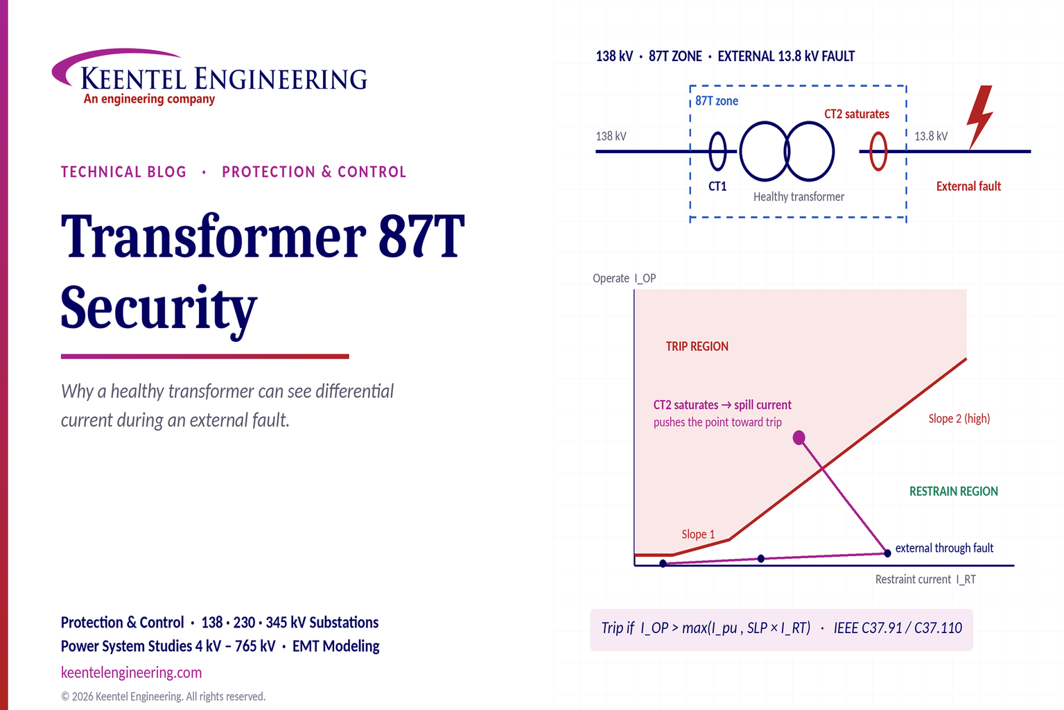
Learn why transformer differential relays detect current during external faults, how CT saturation causes spill current, and how secure 87T protection prevents trips.
By SANDIP R PATEL
•
October 10, 2026
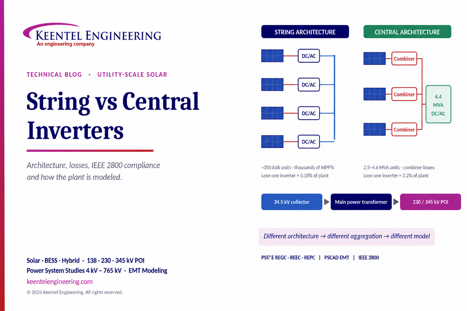
Compare string vs central inverters for utility-scale solar, including efficiency, maintenance, grid compliance, reactive power and interconnection studies.





