
A Coordinated Electric System Interconnection Review—the utility’s deep-dive on technical and cost impacts of your project.
Challenge: Frequent false tripping using conventional electromechanical relays
Solution: SEL-487E integration with multi-terminal differential protection and dynamic inrush restraint
Result: 90% reduction in false trips, saving over $250,000 in downtime
ERCOT enforces all of the above through simulation, which means your model is your compliance case. The bar is now high:
- Whole-facility scope. The model must represent everything the IT load, the UPS and power conversion, the cooling plant, the protection and control systems in formats compatible with ERCOT's study platforms (PSS/E, PSCAD, TSAT).
- Real control loops, not approximations. Generic textbook representations are unacceptable. The model must capture the actual inner control behavior of your power electronics.
- Hardware-validated converter models. For electronic loads, the PSCAD model must be benchmarked against actual hardware testing including voltage ride-through and subsynchronous response. A model assembled from standard PSCAD library blocks fails by definition, because a generic block has never been tested against your vendor's hardware. The good news: validation is a hardware-type test, so results for a given converter product are reusable across every facility that uses it.
- Format migration. Facilities that previously submitted the older composite load model (CMLD) format must transition to EPRI's PERC1 format.
- Three checkpoints. Models are reviewed before the stability study begins (no model, no study), before each quarterly stability assessment, and for electronic loads one final time before energization, when you must submit as-built models with a documented comparison against the previously studied data and a sworn attestation that the model matches actual field settings. ERCOT's review takes 10 business days, extendable by 20 put it on your critical path.
- A living obligation. Change your technology, controls, or relay settings in a way that affects ride-through including converting a crypto mining site to an AI data center — and you've triggered a new interconnection study, even if your megawatts don't change.
| Parameter | Detail |
|---|---|
| System | 230 kV / 138 kV transmission corridors, wind and wet-snow icing exposure |
| Data basis | 15 years of minute-resolution forced-outage records + regional weather observations |
| Core methods | Event grouping, MVA performance curves, time-to-95%-restore, area outage rate curves, fragility modeling, rerun-history benefits, exceedance and log-domain risk metrics |
| Headline result | ≈85% of maximum resilience benefit at 60% of original capital; worst-event restoration window cut from 11 days to 5 in rerun-history terms |
| Decision supported | Capital portfolio selection; resilience plan filing; post-investment verification framework |
| System / Topic | Governing Standard(s) | What It Controls |
|---|---|---|
| Overall plant electrical distribution | IEEE 141 (Red Book); IEEE 666 | Distribution architecture, voltage selection, design of generating station auxiliary service systems |
| Power system studies | IEEE 399 (Brown Book); IEEE 551 | Load flow, symmetrical/asymmetrical short circuit, motor starting methodologies down to the lowest LV panelboard |
| Protection & coordination | IEEE 242 (Buff Book); IEEE 3004.5; IEEE C37 series | Generator relaying (21, 59N, 87G), time-current coordination, selective clearing between LV and MV tiers |
| GSU / UAT / SST transformers | IEEE C57.12.00 and C57 family | Transformer ratings, impedance, testing, loading |
| HV switchyard breakers | IEEE C37.06 | AC high-voltage circuit breaker preferred ratings |
| MV switchgear (13.8 kV) | IEEE C37.20.2; IEEE C37.20.7 | Metal-clad construction, compartmentalization, vacuum breakers; arc-resistant design with plenum venting |
| MV cable | UL 1072; ICEA S-93-639 (NEMA WC 74) | Type MV-105 shielded cable, 133% insulation level for HRG systems |
| LV switchgear (480 V) | IEEE C37.13; UL 1558 | Metal-enclosed LV power circuit breaker switchgear to 635 V, draw-out ACBs with electronic trip units |
| Motor control centers | UL 845; NEMA ICS 18 | LV-MCC construction, MCCB/MCP protection for motors under ~200 HP |
| Motors | NEMA MG-1 | Motor performance, starting characteristics, service factors |
| DC & battery systems | IEEE 485; IEEE 946 | Lead-acid battery sizing (125/250 VDC), DC auxiliary system design |
| Grounding | IEEE 80; IEEE 142 (Green Book) | Ground grid step/touch potential limits; system grounding including high-resistance grounding |
| Lightning protection | IEEE 998 | Direct-stroke shielding of switchyard and outdoor generator structures |
| Arc flash & electrical safety | IEEE 1584; NFPA 70E | Incident energy calculation; worker safety boundaries and PPE |
| Fire protection | NFPA 850 | Fire protection and risk management for combustion turbine generating plants |
| Installation code | NEC (NFPA 70); NESC | Wiring methods inside the plant fence; overhead/outdoor clearances at the switchyard |
| Interconnection & compliance | FERC LGIP; NERC MOD-025/026/027, PRC-019/024/029, FAC-008 | Interconnection process, model validation, protection/ride-through coordination, facility ratings |
| IFC / Construction Deliverable | Purpose |
|---|---|
| Stamped IFC packages | Legal basis for construction; P.E. responsible charge |
| Final relay settings & TCCs | Protection as-installed matches the coordination study |
| Calculation archive | Owner records; NERC audit evidence trail |
| Commissioning procedures | Safe, sequenced energization; MOD field testing |
| Construction support | RFIs, field changes, FAT/SAT witness |
| As-builts & model handoff | Operating baseline; future study currency |
| Metric | Outcome |
|---|---|
| Defects found pre-occupancy | Three topology defects and one settings-mismatch family corrected before load migration; the shared-switchboard defect alone would have invalidated the concurrently-maintainable claim on day one |
| IST findings | Fourteen additional discrepancies surfaced under scenario testing (control logic, alarm mapping, one generator sequencing fault) — all closed before handover instead of during operations |
| Black-building test | Passed on second execution; the first attempt exposed the generator sequencing fault under true block load, exactly the failure the compressed plan would never have found |
| Handover quality | Operations team certified on the actual failure scenarios; corrected EOPs and settings documentation delivered as controlled documents |
| Business outcome | Occupancy proceeded three weeks behind the original date — against an independent estimate that the uncorrected sequencing fault carried a high probability of a full facility outage within the first year |
Part 2 — Frequently Asked Questions: Large Load Interconnection
An electric grid must remain in continuous balance — generation onto the grid must equal consumption from it at every instant. PJM achieves this balance, and prices it, through a layered market architecture. Each layer operates on a different time horizon, and each one touches project economics differently.
| Domain | Key Standards / Codes | What They Govern |
|---|---|---|
| Fire safety | NFPA 855; UL 9540 / UL 9540A | Installation requirements, separation, gas management; system safety listing and thermal-runaway fire testing |
| Grid interconnection | IEEE 1547 (distribution); IEEE 2800 (transmission IBRs) | Ride-through, reactive capability, power quality, and performance at the point of interconnection |
| Power quality | IEEE 519 | Harmonic distortion limits at the PCC |
| Protection & grounding | IEEE 80 / 81 / 142; C37 series | Grounding system design and testing; protective relaying |
| Reliability compliance | NERC standards (incl. PRC ride-through requirements) | Registered-entity obligations for grid-connected storage |
Grid-Forming vs. Grid-Following BESS Inverters: What Actually Changes Inside the Control Loop — and Inside Your Interconnection Study
Aug 15, 2026 | Blog
A Keentel Engineering Grid IQ technical guide for utility planners, interconnection engineers, and storage developers
Introduction: A Two-Panel Diagram That Hides a Decade of Engineering
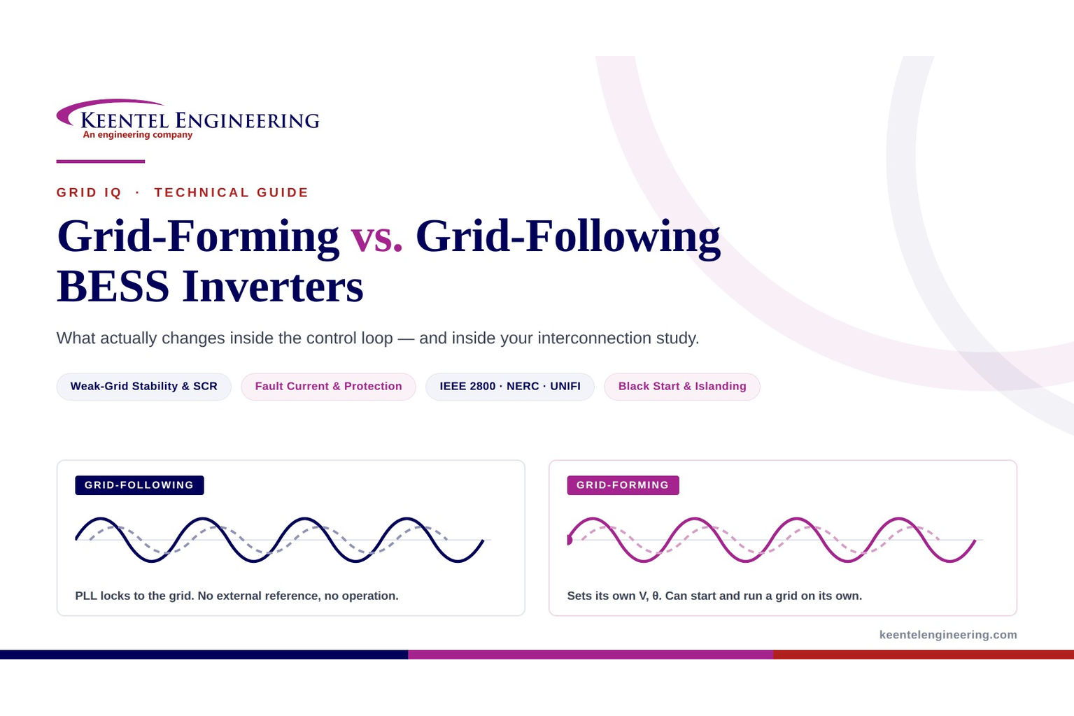
If you have sat in an interconnection study review in the last three years, you have seen some version of the comparison graphic that prompted this article. On the left, a grid-following (GFL) inverter: a phase-locked loop (PLL) reading a transmission-grid voltage waveform, an injected current that dutifully follows it, and the caption "needs an existing grid to lock onto." On the right, a grid-forming (GFM) inverter: a self-generated voltage reference V, θ, a current that follows its own waveform, and the caption "can start and run a grid on its own."
The diagram is correct. It is also, on its own, dangerously incomplete — because it implies the difference is a binary switch, and it implies the GFM column is simply better.
Neither is true. The real difference is a change in what the converter
regulates over a specific time frame, with consequences that propagate all the way out to your short-circuit model, your relay settings, your PSCAD study scope, and your interconnection agreement date. And the GFM column carries a set of hard engineering constraints — current limiting, transient stability under saturation, headroom, and its own weak-and-strong-grid instability modes — that rarely make it into the marketing.
This guide unpacks what the two panels of that graphic actually mean at the control-loop level, what the field evidence says, where the standards and grid codes now sit as of mid-2026, and how the choice shows up in real project work.
1. The Definition That Matters (and the One to Stop Using)
The most common definition — "grid-following controls current, grid-forming controls voltage" — is a useful mnemonic and a poor engineering specification. Both devices ultimately switch semiconductors to produce a voltage; both end up injecting a current.
NERC, the UNIFI Consortium, and ESIG have converged on a time-domain definition instead, and it is the one that belongs in your interconnection documents:
Grid-forming: maintains an internal voltage phasor — AC voltage magnitude and angle — that is constant or nearly constant in the sub-transient to transient time frame.
Grid-following: maintains its output current phasor magnitude and angle during the sub-transient period, then transitions to power control in the transient time frame.
The sub-transient window is roughly 0–5 cycles; the transient window is tens of cycles. UNIFI is careful to note these are general descriptions rather than hard limits.
Why the framing matters: it makes the distinction testable. UNIFI Version 3 (January 2026) converts "voltage source behind an impedance" into a measurable criterion — high-frequency voltage-phasor stiffness demonstrated by a passive response rising ten-fold per decade of frequency, or upper gain bounds of 0.005–0.02 p.u./p.u., or an estimated series inductance below a maximum within a ±5 Hz band. You can put that in a functional specification. You cannot put "controls voltage instead of current" in one.
It also disposes of a persistent misconception: grid-forming is not the same thing as islanding capability, and it is not the same thing as black start. UNIFI V3 organizes GFM into four capability tiers — Tier 1 (voltage magnitude support only, e.g. a GFM STATCOM), Tier 2 (voltage angle and frequency support with minimal islanding), Tier 3 (full support with extended islanding — where grid-scale BESS sits), and Tier 4 (Tier 3 plus black start). A device can be legitimately grid-forming and still be unable to energize a dead bus.
2. Grid-Following: How It Works, and Exactly Where It Breaks
2.1 The architecture
A GFL plant is, electrically, a Norton equivalent: a controlled current injection behind a large shunt impedance. Its control chain is familiar:
- Measure PCC voltage.
- The PLL estimates the voltage phase angle and establishes a rotating dq reference frame.
- Outer loops (active power / DC-link voltage, reactive power / AC voltage) generate d- and q-axis current references.
- Fast inner current loops drive the modulator to track those references.
The critical property is that the plant has no angle of its own. Its angle is a measurement of the grid's angle. That single fact explains every GFL limitation that follows.
Remove the external voltage reference and the PLL has nothing to track — which is why ESIG's capability comparison lists black start for GFL as "not usually possible." It is not a tuning problem. It is architectural.
2.2 The weak-grid instability mechanism
As the Thévenin impedance seen at the POI rises — as short-circuit ratio falls — the inverter's own current injection begins to materially move the PCC voltage angle. The PLL measures that movement. The controller responds. The response changes the injection. The loop gain of this positive-feedback path scales with grid impedance.
The mechanism has been characterized in impedance terms: the PLL introduces a negative resistance in the Z_qq impedance component in the low-frequency range, and the second-order low-pass filter used in more sophisticated PLL structures can further degrade damping in weak grids. In one national-laboratory impedance study, instability was triggered as PCC short-circuit ratio fell from 2 to 1.15, producing a 3 Hz oscillation on a line trip and an undamped 10 Hz oscillation after curtailment.
The design trade-off is unforgiving and well quantified. CIGRE small-signal analysis found that a PLL bandwidth of 11 Hz produced a 44 rad/s mode with poor damping, while reducing bandwidth to 4 Hz eliminated the mode and achieved 86% damping at SCR = 2.3 — at the cost of response speed to genuine grid changes. You buy weak-grid stability with slower dynamics.
2.3 On the SCR threshold — resist the urge to quote a single number
Screening heuristics in wide circulation place "strong" above SCR 3.0, "weak" between 2.0 and 3.0, and "very weak" below 2.0. These are useful for deciding when a detailed EMT study is required. They are not a physical instability boundary, and presenting them as one will get you challenged in a study review.
NERC's own position is explicit: "There is no specific short circuit threshold one can consider as a 'weak grid.'" Weak-grid problems are system-specific. And CIGRE's comparative analysis found that a well-tuned GFL resource held 50% damping at post-contingency SCR of 0.9, with limitations appearing only in exceptional post-contingency scenarios near SCR 1.0 — while a poorly tuned GFM exhibited instability comparable to GFL.
The defensible framing: SCR 2–3 is a study-trigger band; the true limit is tuning-dependent and, for modern well-tuned equipment, sits considerably lower.
What grid codes do pin down are test floors. UNIFI V3 requires testing at SCR of 10, 5, 3, 1.5 and 1.2 (X/R = 6) with no tripping. AEMO's voluntary specification steps SCR from 20 down through 10, 3, 2, 1.5 to 1.25, with stability at 1.25 as the pass criterion. MISO's draft framework uses a ramp-down to SCR 1.25.
2.4 The field evidence: Odessa I and Odessa II
The strongest real-world case that PLL-based synchronization is a bulk-system reliability concern comes from ERCOT.
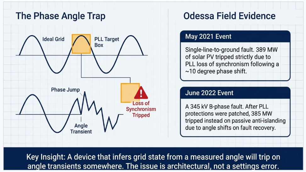
Odessa, 9 May 2021. A single-line-to-ground fault on a GSU transformer near Odessa produced a total 1,340 MW reduction, of which 1,112 MW was solar PV. The single largest identified failure mode was PLL loss of synchronism at 389 MW — inverters tripping because the voltage phase angle shifted roughly 10 degrees during the fault. Two facilities alone accounted for 239 MW and 150 MW. A further 153 MW was legacy momentary cessation below 0.9 p.u. voltage.
Odessa, 4 June 2022. A B-phase-to-ground fault on the 345 kV system caused 2,555 MW of loss, including 1,711 MW of solar PV across fourteen facilities. The breakdown is instructive: inverter AC overcurrent 459 MW; passive anti-islanding (phase jump) 385 MW; AC overvoltage 295 MW; DC voltage unbalance 211 MW.
The critical detail is that second line item. Following the 2021 event, PLL loss-of-synchronism protection had been disabled at many facilities. Inverters from the same manufacturer then tripped on passive anti-islanding, which misinterpreted the phase-angle shift on fault recovery as an islanding signature — triggering when the angle between voltage and current phasors exceeded 15 degrees within 500 ms.
That is the whole argument in one paragraph. Patching a PLL symptom moved the failure to an adjacent phase-angle-sensitive function, because a device that infers grid state from measured angle will trip on angle transients somewhere. The issue is architectural, not a settings error.
3. Grid-Forming: Voltage Source Behind an Impedance
3.1 The architecture
A GFM converter behaves as a Thévenin equivalent — a voltage source behind an impedance. It establishes its own internal voltage magnitude and angle, and active and reactive power flow arise from the angle and magnitude difference between that internal phasor and the grid, exactly as they do for a synchronous machine.
The consequences follow directly:
- Synchronization is inherent, not measured. There is no PLL in the primary control path, so there is no PLL to destabilize.
- Inertial response is inherent. A change in system frequency changes the angle difference, which changes power, with no frequency measurement and no measurement window.
- Phase-jump response is inherent. A step in grid angle immediately changes the angle difference and therefore the power — opposing the disturbance.
- The device can energize a dead network, subject to sufficient DC energy, overload capability for transformer inrush, and a ground reference.
3.2 The five control families
"Grid-forming" is a behavior class, not an algorithm. Five families dominate, and the distinctions matter when you are reviewing a vendor's model.
Droop control
Linear P–ω and Q–V characteristics. Enables system-wide synchronization with all units converging on a common frequency, and supports parallel operation without communications. The most common approach in microgrids, and deployed at scale in grid-connected BESS. Its known pitfall is the low-pass filter on the power measurement, which is the knob balancing harmonic rejection against response speed; it also lacks explicit inertia unless added.
Virtual synchronous machine (VSM) / synchronverter
Emulates synchronous machine dynamics digitally, with virtual inertia, damping and flux linkage as tunable parameters. ESIG identifies VSM as the most common approach in GFM pilots, largely because its behavior is familiar to system planners. The trade-off: you inherit the machine's pathologies along with its virtues, including its oscillatory modes, and the parameter tuning burden is real.
Virtual oscillator control (VOC) / dispatchable VOC (dVOC)
Emulates a nonlinear oscillator whose natural frequency is nominal grid frequency. Droop behavior emerges from the dynamics rather than being imposed. Offers near-instantaneous synchronization and load sharing using local measurements only. Still largely in pilot and development phase.
Matching control
Emulates synchronous behavior from the DC side — the DC-link voltage plays the role of rotor speed. Conceptually distinct because it structurally couples DC-bus energy to frequency rather than treating DC dynamics as an afterthought.
Power synchronization control (PSC)
Notable for preserving voltage-mode operation during faults rather than reverting to current-source behavior — directly relevant to the current-limiting problem discussed in Section 5.
3.3 Quantified performance expectations
Specifications have moved from principles to numbers. Representative requirements:
| Requirement | UNIFI V3 (Jan 2026) | AEMO voluntary spec | NESO GBGF (Guidance Note Issue 4) |
|---|---|---|---|
| Phase-jump active power response | ≥0.2 p.u., with ≥90% in the first line cycle (10° jump) | ≥0.2 p.u. peak, within 15 ms for a 10° step | Response within 5 ms; phase-jump angle withstand ≥60° |
| Voltage-step reactive response | ≥0.03 p.u. within 6 line cycles, ≥90% in first cycle | Voltage-source response within 5 ms | Within 5 ms |
| Inertia | H > 2.5 s, measured over the first 500 ms of a RoCoF event | Inherent, no frequency measurement; H tunable | Active RoCoF Response Power; ≥2 Hz/s withstand over rolling 500 ms |
| Steady-state droop | 0.01–0.05 p.u./p.u. (P–f and Q–V) | Not prescribed | — |
| Weak-grid stability | Stable to SCR 1.2 | Stable to SCR 1.25 | — |
| Damping | Non-negative resistance across resonance frequencies | Impedance phase within −90° to +90°, 10–500 Hz | Damping factor 0.2–5.0; control bandwidth <5 Hz |
Two things stand out. First, everyone agrees on the physics — voltage-source behavior in the sub-transient frame, inertia without frequency measurement, weak-grid stability, positive damping. Second, nobody agrees on the numbers. A vendor cannot build one product that "complies" globally; compliance is per-market.
4. Side-by-Side: The Engineering Comparison
| Attribute | Grid-following (GFL) | Grid-forming (GFM) |
|---|---|---|
| Equivalent circuit | Controlled current source behind high impedance (Norton) | Voltage source behind an impedance (Thévenin) |
| Synchronization | PLL measures grid angle | Inherent; internal angle from power balance |
| Requires an external voltage reference | Yes | No |
| Behavior at very low SCR | Degrades; PLL introduces negative resistance | Stable by design; tested to SCR ≈1.2 |
| Behavior at very high SCR | Robust | Can destabilize if poorly tuned — a real, under-discussed failure mode |
| Damping | Synthetic; requires RoCoF measurement, hence a measurement delay | Inherent; sub-cycle |
| Phase-jump response | Vulnerability (a trip cause) | Design requirement (a response) |
| Black start | Not usually possible | Possible, with sufficient DC energy, overload margin and grounding |
| Islanded operation | No (requires a forming source) | Yes, subject to energy and capacity |
| Sustained fault current | ~1.0–1.5 p.u. | ~1.1–1.5 p.u. typically; higher sub-cycle before control acts |
| Damping of system oscillations | Can contribute negatively | Can provide broadband positive damping |
| Implementation | Standard | Predominantly firmware/controls; hardware only for overcurrent margin, black start, energy buffer |
| Maturity | Fully commercial | Commercial for BESS; not proven for wind turbines |
5. The Hard Part: Current Limiting and Transient Stability
This is the section that separates a serious GFM discussion from a brochure. It is also where most project risk actually lives.
5.1 The fundamental constraint
A synchronous machine's fault contribution is set by physics — it will deliver several times rated current, roughly 3–5× per ESIG's comparison, with higher sub-transient values, because its thermal mass and magnetic circuit permit it. An inverter has essentially no thermal mass. Its current limit is instantaneous and strict, set by the semiconductor's safe operating area. Exceeding it, even momentarily, is not permitted.
Reported GFM fault-current figures diverge widely, and the divergence is a reporting artifact worth understanding:
- ESIG: IBRs provide 1–1.5× rated current.
- Sandia expert interviews: most GFM inverters provide at most 1.1–1.2 p.u.; Sandia's own measurements of single-phase GFM units ranged 1.3–2.25 p.u. depending on manufacturer.
- NREL's GFM research roadmap cites sub-transient values of 4–6 p.u. for under 10 cycles, with steady-state below 2 p.u.
- UNIFI's illustrative short-term rated current: 1.5× full-rated for 2 seconds.
These are not contradictory. The 4–6 p.u. figures describe sub-cycle behavior limited by internal impedance before control acts; the 1.1–1.5 p.u. figures describe sustained contribution after limiting engages. Conflating them is the single most common error in GFM writing, and it will produce a short-circuit model that does not match reality.
5.2 Why limiting is hard to do well
Every current-limiting strategy trades something away:
- Current-reference saturation. Fast and accurate — but the device becomes a current source. Voltage-source behavior, the thing you bought, is lost precisely when you need it.
- Switch-level limiting. Faster than anything else, acting within a few switching cycles — but it bypasses the entire GFM control structure, risking controller instability and severe waveform clipping.
- Virtual impedance. Subtracts a synthetic voltage drop from the reference, requiring |Z_vi| ≥ E₀/I_max. Retains voltage-source behavior, at the cost of slower action and reduced small-signal margin.
- Power set-point modulation. Simple, but the governing equations contain no dependence on I_max, so current limiting within the inverter's boundaries cannot be guaranteed.
- Voltage-based limiting. Documented drawback: the inverter becomes a controlled current source during limiting, similar to a GFL inverter, which can have a destabilizing effect in weak grids — the exact failure mode GFM was procured to avoid, reappearing at the worst moment.
- Hybrid schemes. Current-reference limiting for immediate action, virtual impedance taking over — best trade-off, most complex implementation.
5.3 The transient stability consequence
Under normal operation the power-angle relationship is the familiar P = (E·V_g / X_g)·sin δ. Once current limiting engages, it becomes P = V_g·I_max·cos(δ − φ) — sinusoidal to cosinusoidal. Output power drops immediately, the internal reference angle accelerates under droop dynamics, and loss of synchronism follows if the critical clearing angle is exceeded.
Two mitigations matter in review:
- Increasing the current-angle priority φ raises the critical clearing angle — but φ cannot be pushed too far without confining the unit to permanent limiting.
- Virtual impedance X/R is decisive: a purely resistive virtual impedance can quickly cause instability through a small critical clearing angle, while an inductive one substantially increases it. A ratio of X_vi/R_vi ≈ 5 has been proposed as a workable compromise.
Integrator windup in the cascaded loops is a named additional hazard requiring explicit anti-windup logic.
5.4 Headroom — and a genuine disagreement worth knowing
A GFM inverter's ability to hold its internal voltage phasor against a disturbance is bounded by available current. Dispatched at 1.0 p.u., there is nothing left with which to form voltage.
Here the specifications diverge, and the divergence is substantive:
- UNIFI and ESIG hold that a guaranteed power margin must be reserved to enable a firm inertia response independent of base loading, and that GFM performance may be reduced at or near power, energy or current limits.
- MISO deliberately targets capabilities that do not require holding capacity or energy in reserve, explicitly avoiding requirements that would force hardware oversizing or materially affect state-of-charge management.
- ERCOT's Advanced Grid Support takes the same position: AGS does not require additional short-circuit current capability, does not require reserving capacity or state of charge for a specified inertia contribution, and is framed as achievable without additional hardware or maintained energy reserves.
These positions are reconcilable once you scope them. Core voltage-source behavior is essentially free in firmware. Firm, contracted inertia and fast frequency response services are not — those require reserved power and energy, and that is a commercial decision, not a control-design one.
One genuine gap: there is essentially no authoritative quantitative literature on GFM-specific thermal or battery-degradation implications from continuous small active-power injections for damping and inertia. Treat vendor claims in this area as unverified.
6. Protection: The Consequence Nobody Budgets For
Traditional overcurrent protection assumes fault current substantially exceeds load current. In a system where the dominant sources contribute 1.1–1.5 p.u., distinguishing a fault from a temporary overload by magnitude alone becomes unreliable. ESIG's recommendation is to move toward differential protection and communications-assisted transfer-trip or blocking schemes rather than magnitude-based discrimination.
Specific findings that should shape your protection scope:
- Negative sequence. GFM IBRs — like GFL IBRs and synchronous machines — should provide negative-sequence current during faults, because a great deal of conventional protection depends on negative-sequence quantities. IEEE 2800-2022 already requires incremental negative-sequence reactive current dependent on negative-sequence terminal voltage.
- Distance protection. GFM units with a hard current limiter can cause distance-relay under- or overreach. GFM units using virtual impedance can potentially enable correct operation — a direct, practical engineering argument for VI-based limiting that goes beyond stability.
- Power swing protection. No published literature specifically examines GFM impact, though practitioners consistently identify it as a major concern. This is an open risk, not a solved problem.
- Waveform quality. Hardware limiting and fast switch action produce distorted waveforms in the first few cycles before software control restores a sinusoidal current — relevant to any relay algorithm relying on early-cycle phasor estimation.
- Expert consensus is that GFM units should remain in GFM mode during faults, supporting voltage while limiting current, rather than switching to a following mode.
Sandia has published seven named knowledge gaps in this area, including measured GFM fault currents, ride-through strategies aligned with relay operation, GFM–GFL interaction during and after faults, and adequate GFM-plus-relay models for protection studies. If a project's protection philosophy is being built on GFM assumptions, that scope needs EMT-based validation, not a spreadsheet.
Australia has made this the explicit gating question. AEMO has stated that GFM BESS has demonstrated voltage-waveform stability but is not yet confirmed to deliver protection-quality fault current — sufficient in magnitude, duration and sequence composition for relays — and has launched a dedicated Grid-Forming Inverter Protection-Quality Fault Current Trial to find out, with contracts running from July 2026. This is despite an Australian grid-scale battery fleet above 9,000 MW and a NEM pipeline of 33.2 GW in which roughly 74% is grid-forming.
7. Four Claims to Push Back On
GFM provides inertia equivalent to a synchronous machine
It does not, and the field data is unambiguous. During a 12 June 2023 NEM frequency event with RoCoF near −0.17 Hz/s, an Australian grid-forming battery's inertial response peaked roughly 480 ms later than a comparable synchronous generator. At the 200 ms mark, the synchronous machine had released 13.7% of its two-second response; the battery had released 2.0%. The Australian program's own conclusion is that GFM inertia differs qualitatively and quantitatively from synchronous inertia and is not a direct replacement for it. It is genuinely valuable and genuinely different.
The Iberian blackout proves we need more inertia
It does not. The ENTSO-E expert panel's final report, published 20 March 2026, concluded that even with higher system inertia the loss of synchronism would not have been avoided — simply adding more rotating mass would not have been enough. The event was driven by voltage and reactive-power control gaps and oscillations, including a 0.63 Hz converter-driven forced oscillation and a 0.2 Hz inter-area mode in the preceding half hour, with renewables in fixed power factor mode and conventional units meeting required reactive output less than 75% of the time. GFM is relevant to that event — but as a source of voltage-source behavior and dynamic voltage support, not inertia. Making the inertia argument from Iberia will be corrected by anyone who has read the report.
More grid-forming is always better
No. ESIG has documented a tested GFM inverter that becomes unstable when short-circuit ratio rises above 4 — the mirror image of the GFL weak-grid problem, and a predictable one: voltage sources paralleled through low impedance exchange large circulating currents for small angle errors. Analytical work reaches the same conclusion, that too many GFM converters lead to instability and the allocation between GFM and GFL must be balanced. Meanwhile national-laboratory guidance suggests roughly 25–30% GFM penetration as a target and notes stability issues rising above 60–70% instantaneous GFL penetration, while ESIG places the threshold where GFM becomes necessary at around 75–80% IBR penetration. There is an optimum, not a maximum.
GFM is just a firmware setting
Partly. Baseline GFM control — voltage-source behavior, phase-jump response, droop, damping — is predominantly a software matter, and several major Australian projects were commissioned as conventional plants and later retrofitted to GFM through firmware and a connection-alteration process without hardware modification. What costs hardware is
overcurrent headroom beyond the existing rating (oversized semiconductors and cooling), black-start capability, and energy-buffer sizing. Scope those three separately in any budget.
8. The Compliance Landscape as of August 2026
Standards
IEEE 2800-2022 remains the anchor for transmission-connected IBRs, and it is deliberately technology-neutral — it neither requires nor defines
grid-forming controls. That changed structurally in December 2025, when the IEEE Standards Association approved three related projects:
| Project | Scope | Target |
|---|---|---|
| P2800 (revision) | Revision superseding IEEE 2800-2022; expands to inverter/converter-based resources | Dec 2029 |
| P2800a | Amendment: Reduce Barriers for IBRs with Grid-Forming Equipment | Dec 2029 |
| P2800.1 | Recommended Practice for Functional Capabilities and Performance of Grid-Forming Equipment | Dec 2029 |
Note P2800a's framing carefully: it is about removing barriers to GFM, not mandating it. Mandates are coming from grid codes and ISOs, not from IEEE.
IEEE 2800.2-2026, the conformity-assessment recommended practice for test and verification of IBRs interconnecting with bulk power systems, was approved by the IEEE SA Standards Board in February 2026 and published on 30 June 2026. It is not GFM-specific; GFM test and verification is being routed to P2800.1.
At distribution level, the IEEE 1547 series has no grid-forming standard. IEEE 1547-2018 and 1547a-2020 are built around grid-following smart-inverter functions — volt-var, volt-watt, frequency-watt, ride-through. Intentional islanding is handled by IEEE 1547.4-2011, currently under revision. There is no 1547-series project comparable to P2800.1.
NERC's September 2023 white paper, Grid Forming Functional Specifications for BPS-Connected Battery Energy Storage Systems, remains the document most US ISOs are building on. Its three headline functional specifications are phase-jump performance, system-strength support in the sub-transient time scale, and stable operation through and following loss of the last synchronous machine.
UNIFI Version 3 (January 2026) is currently the most quantitatively detailed public specification, and the trajectory from V1's deliberately non-prescriptive "performance principles" to V3's testable numeric thresholds is the story of the last three years in one document series.
On the modeling side, WECC-approved generic GFM models REGFM_A1 and REGFM_B1 are in the standard library, with REGFM_C1 (hybrid control) and REPCGFM_C1 (plant control) advanced through WECC in September 2025. This matters more than it sounds: study-grade generic models are what let a GFM claim survive an interconnection queue.
Grid codes and mandates
There is no US federal grid-forming mandate. FERC Order No. 901 drove the IBR reliability standards program and the registration workplan (completed May 2026, with 531 IBR facilities identified and registration effective 15 May 2026). Order No. 909 approved PRC-024-4 and PRC-029-1 — ride-through and protection settings, not GFM. Notably, FERC explicitly declined a recommendation to require grid-forming capability, saying instead that it encourages NERC to remain proactive in using its standards development authority.
ERCOT is the first US mandate, and it is already in force. NOGRR272 and PGRR121, establishing Advanced Grid Support (AGS) requirements for inverter-based Energy Storage Resources, were approved by the ERCOT Board in September 2025 and by the PUCT in November 2025, effective 1 December 2025. Applicability: ESRs with a Standard Generation Interconnection Agreement dated 1 April 2026 or later. ERCOT separately proposed an AGS Incentive Program in May 2026 (NPRR1333) for resources not otherwise covered — $1,500/MW one-time, availability-adjusted, under a $25 million cap — which remains pending as of August 2026.
If you are developing storage in ERCOT, that SGIA date is now a design gate, not a compliance footnote.
Elsewhere: Great Britain's GC0137 added a GBGF technical specification to the Grid Code as an optional capability, with the current Guidance Note (Issue 4, December 2025) prescribing ≤5 ms response, ≥60° phase-jump withstand, 2 Hz/s RoCoF withstand over a rolling 500 ms window, damping factors of 0.2–5.0, and control bandwidth below 5 Hz. GC0163 (July 2024) removed the restriction to physical impedance, permitting virtual (software) impedance — a meaningful shift toward performance-based rather than method-based compliance. Australia's AEMO specification remains voluntary, with a Technical Requirements Review running to a draft report in Q3 2026, final in Q4 2026, and a rule change to the AEMC targeted for Q1 2027. The EU's ENTSO-E published its Phase II technical report on grid-forming requirements in November 2025, intended for integration into NC RfG 2.0 — but RfG 2.0 has not been adopted, and ENTSO-E's own December 2025 position paper notes the process has been deprioritised with no communicated timeline. Elsewhere, VDE FNN in Germany, RTE in France, Fingrid in Finland and CEN in Chile have mandatory requirements in place.
Markets: capability is running ahead of procurement
The most instructive fact about GFM economics in 2026 is that three sophisticated markets reached three different answers within five months.
- Germany launched market-based procurement of instantaneous reserve (Momentanreserve) on 22 January 2026, with premium products priced at roughly €805–€888.50 per MW·s per year and basic products at €76–€109.50, against 90% and 30% availability requirements respectively. This is a real, bankable revenue stream for grid-forming storage.
- Australia's AEMC decided against creating an operational inertia market in October 2025, finding the benefits outweighed by the cost of designing and running it.
- Great Britain's NESO awarded its Mid-Term (Y-1) Stability Market Round 2 in February 2026 — 7.3 GVA·s of inertia for £10.3 million — and awarded nothing to battery storage, with all grid-forming BESS submissions failing at the technical assessment stage. This despite Stability Pathfinder Phase 2 having contracted five grid-forming batteries in Scotland, and a portfolio of GFM projects at Blackhillock, Kilmarnock South and Eccles collectively contracted for several GVA·s of inertia.
A vendor's summary to ERCOT captures the developer's position exactly: the cost categories are CAPEX for controls and stability buffers, balance of plant, OPEX for state-of-charge recalibration and troubleshooting complexity, time to revenue through extended testing, and revenue risk — "no upside without market."
On cost premium specifically: there is no credible published GFM-versus-GFL cost premium figure from any national laboratory, ISO, or industry consortium. ESIG's position is that enabling GFM controls in a BESS carries low incremental cost when incorporated early in the design process and is materially cheaper than synchronous condensers, STATCOMs or transmission reinforcement. Any specific percentage you encounter online traces to vendor marketing or paywalled market research, not engineering study. Treat it accordingly.
9. Three Anonymized Case Studies
Confidentiality note
The three engagements below are presented in anonymized and generalized form. Ratings, locations, utility identities, dates and specific study results have been altered or aggregated to protect client confidentiality. They are included to illustrate the engineering decision patterns that recur in this work, not to characterize any single project.
Case Study A — Standalone BESS in a Low-SCR Transmission Pocket
Situation. A developer held a queue position for a ~200 MW / 800 MWh standalone battery at a rural 138 kV substation in a region already hosting several hundred MW of utility-scale solar. The transmission provider's screening study returned a composite short-circuit ratio in the low 2s under system-intact conditions and below 1.5 under a credible N-1 outage of the strongest source. The queue cluster restudy identified control-interaction risk and required full EMT analysis.
What the study found
With a conventional grid-following control model, the plant remained stable at system-intact SCR but exhibited poorly damped oscillation in the 5–10 Hz range following the N-1 contingency, with damping falling below acceptable margin as the neighboring solar plants were dispatched to high output. Sensitivity runs showed the mechanism was PLL-driven: reducing PLL bandwidth restored damping but degraded the plant's reactive response speed enough to threaten a separate voltage-recovery requirement. The two requirements could not be satisfied simultaneously with GFL controls at that location.
Re-running the same contingency set with the vendor's grid-forming control model — a droop-based implementation with inductive virtual impedance for current limiting — eliminated the oscillatory mode across the full dispatch sweep and remained stable through the SCR ramp-down to 1.25.
Outcome and lessons
The developer elected GFM. Two points proved decisive in negotiation with the transmission provider, and both generalize:
- The alternative was network reinforcement. The comparison was never GFM cost versus GFL cost; it was GFM cost versus a synchronous condenser or a line upgrade with a multi-year schedule.
- The current-limiting method was a study input, not a detail. An early vendor model using current-reference saturation showed loss of synchronism for a close-in three-phase fault at the reduced-SCR condition. The virtual-impedance variant did not. Had the model been accepted without interrogating the limiter, the study would have produced a stable-looking result for a plant that was not.
The project also absorbed an unbudgeted cost: the plant's short-circuit contribution changed enough between GFL and GFM assumptions to require the interconnecting utility's protection group to revisit relay coordination on two adjacent lines.
Case Study B — Industrial Campus Microgrid with Islanding and Black Start
Situation. A manufacturing client with a process load that cannot tolerate a momentary interruption sought resilience against a distribution feeder with a poor historical outage record. The scope was a ~15 MW / 60 MWh BESS alongside existing rooftop and carport PV and two legacy standby diesel generators, with a requirement for seamless transition to island and the ability to restore the campus from a fully de-energized state.
Engineering decisions
Grid-forming was not optional here — islanding and black start are Tier 3 and Tier 4 capabilities, and no grid-following architecture provides them. The consequential decisions were elsewhere:
- No mode switching. The initial vendor architecture switched between GFL control when grid-connected and GFM control when islanded, gated by a PCC status signal. Comparative studies of transition schemes show this approach settling in roughly 2 seconds on islanding, with voltage dipping to about 0.92 p.u. and a frequency overshoot near 61.2 Hz — against 2 cycles and no voltage transient for an architecture that stays in GFM mode continuously and maintains the same operating point through the transition. For a process load that trips on a 100 ms sag, that difference is the entire project. The design was changed to continuous GFM operation.
- Sizing was driven by inrush, not energy. Black start required overload headroom for transformer energization. A controlled voltage ramp on the order of 0.1 p.u./s was adopted for soft-start, and interconnection transformers were configured delta–wye-grounded to provide a ground reference for the island without the substation source.
- Load shedding was designed in, not bolted on. Shedding roughly one-fifth of non-critical load during restoration materially reduced the required GFM capacity and therefore the capital cost of the battery.
- Protection was redesigned, not re-set. In islanded operation the available fault current fell to roughly 1.2 p.u. of the BESS rating. Overcurrent coordination built for a utility source was unusable. The scheme moved to differential protection on the campus loop with a communications-assisted blocking scheme, plus a separate settings group for islanded operation.
Outcome and lessons
The islanded transition met the process requirement. The generalizable lesson is that the protection redesign, not the battery, was the schedule-critical path — and it was discovered late, because the initial scope treated the BESS as an equipment purchase rather than a change to the campus's fault-current source.
Case Study C — ERCOT Storage Portfolio and the Advanced Grid Support Deadline
Situation. A portfolio owner held several inverter-based Energy Storage Resource positions in ERCOT at different stages: two with executed interconnection agreements predating the AGS applicability date, and three whose agreements would be executed after it. The owner's initial assumption was that AGS was a future concern and that a firmware update near commissioning would satisfy it.
What the review found
Three issues surfaced, each of which recurs across the ERCOT queue:
- The applicability boundary split the portfolio. The projects with earlier agreements were outside the mandate; the later ones were inside it. Two units of the same model, from the same supplier, on the same balance sheet, now faced different requirements. The commercially rational move — standardizing on AGS-capable configuration across the portfolio — was only obvious once the split was quantified.
- Model quality, not inverter capability, was the binding constraint. The requirement is not merely that the equipment be capable; it is that the plant demonstrate compliance through model quality and unit testing. The supplier's available EMT model for one platform did not reproduce the required phase-jump behavior with the settings proposed for the site, and the plant-level controller model had not been validated in combination with the unit model. Resolving that took longer than any hardware question.
- The scope of AGS was narrower than assumed — in the owner's favor. ERCOT's requirement does not oblige additional short-circuit current capability and does not require reserving capacity or state of charge for a specified inertia contribution. Once that was established, the projected commercial impact on merchant dispatch was far smaller than the owner's initial planning assumption. The cost of AGS was a testing and modeling cost, not an energy-arbitrage cost.
Outcome and lessons
All five projects proceeded to an AGS-capable configuration. The transferable lesson is that in a mandate regime, the compliance risk sits in model fidelity and test evidence rather than in the inverter itself — and that engineering review should start at the interconnection-agreement date, well before equipment selection.
10. A Practical Selection Framework
Grid-forming is not a default and not a differentiator on its own. Work through these in order:
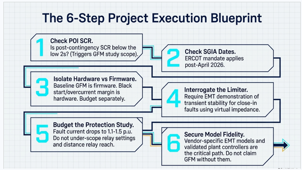
- What is the SCR at the POI — system-intact and post-contingency, composite rather than plain? If post-contingency composite SCR approaches or falls below the low 2s, GFM belongs in the study scope.
- Is there a mandate? In ERCOT, check the SGIA date first. In Europe, check the national TSO requirement, not the pending EU code.
- Is islanding, seamless transition, or black start in scope? If yes, GFM is required — and specify continuous GFM operation, not mode switching.
- What is the alternative being displaced? GFM's business case is almost never against GFL. It is against synchronous condensers, STATCOMs, curtailment, or network reinforcement.
- Is there a revenue mechanism? Germany pays for inertia. ERCOT has proposed an incentive. Great Britain's enduring stability market has not yet awarded a battery contract. This determines whether GFM is a cost or an asset.
- Interrogate the current limiter. Ask which method the vendor uses, and require the EMT model to demonstrate transient stability for close-in faults at post-contingency SCR. Virtual impedance with an inductive X/R is materially better behaved than current-reference saturation.
- Separate firmware scope from hardware scope. Baseline GFM behavior is controls. Overcurrent margin, black start and energy buffer are hardware and belong in a separate line item.
- Budget the protection study. Fault-current contribution, distance-relay reach, negative-sequence availability and power-swing behavior all change. This is the most commonly under-scoped item in GFM projects.
- Check model availability early. WECC-approved generic models exist. Vendor-specific EMT models and validated plant controllers are the long pole.
- Confirm the mix, not just the technology. Both too little and too much GFM cause problems. The allocation between GFM and GFL at a common electrical area is a study question.
11. Frequently Asked Questions
Q: Is grid-forming just a software upgrade?
Baseline GFM control is predominantly firmware — voltage-source behavior, phase-jump response, droop and damping. Several large Australian batteries were commissioned as conventional plants and later converted to grid-forming through firmware and a regulatory connection-alteration process, without hardware modification. What requires hardware is overcurrent headroom beyond the existing rating (semiconductors and cooling), black-start capability, and energy-buffer sizing. Budget those separately.
Q: Does a grid-forming inverter provide real inertia?
It provides an inherent inertial response — power changes with the angle difference, with no frequency measurement and no measurement window — which is qualitatively different from a grid-following inverter's synthetic inertia. But it is not equivalent to a synchronous machine. In a documented Australian frequency event, the grid-forming battery's response peaked roughly 480 ms after the synchronous unit's, and at 200 ms the machine had delivered 13.7% of its two-second response against the battery's 2.0%. GFM inertia is valuable and is not a drop-in substitute.
Q: How much fault current does a grid-forming BESS contribute?
Sustained contribution after current limiting engages is typically 1.1–1.5 p.u. of rating, though measured values as high as 2.25 p.u. have been reported for some units. Sub-cycle, before control acts, internal impedance can permit substantially higher transient values — figures of 4–6 p.u. for under 10 cycles appear in the literature. Do not conflate the two: your short-circuit model needs the sustained figure, and your relay-performance study needs both.
Q: Below what short-circuit ratio does a grid-following plant become unstable?
There is no universal number, and NERC explicitly declines to set one. The commonly quoted 2–3 band is best used as a screening trigger for detailed EMT study. CIGRE analysis found a well-tuned GFL resource holding 50% damping at post-contingency SCR of 0.9, with problems appearing only near SCR 1.0 — and found that a poorly tuned GFM performed no better than GFL. Tuning matters more than the nameplate architecture.
Q: Can grid-forming inverters operate in parallel with each other?
Yes, and this is routine in microgrids — droop-based GFM units share load autonomously without communications. At transmission scale it is less settled. Documented hardware-in-the-loop black-start work with parallel GFM units at a 5:1 capacity ratio succeeded but flagged reliable parallel operation as requiring further research and explicit interoperability standards covering steady-state and fault/overload behavior between GFM units from different vendors.
Q: Can you have too much grid-forming?
Yes. A tested GFM inverter has been documented becoming unstable when short-circuit ratio rises above 4 — voltage sources paralleled through low impedance exchange large circulating currents for small angle errors. Analytical work reaches the same conclusion. Meanwhile national-laboratory guidance suggests around 25–30% GFM as a useful target. Think in terms of an optimum, not a maximum.
Q: Does grid-forming break my protection scheme?
It changes the assumptions the scheme was built on. Fault current magnitude falls far below synchronous-machine levels, making magnitude-based discrimination unreliable; a hard current limiter can cause distance-relay under- or overreach, while virtual-impedance limiting can preserve correct operation; and power-swing protection behavior with GFM is genuinely under-studied. Plan for differential and communications-assisted schemes, and require negative-sequence current capability explicitly.
Q: What is the cost premium for grid-forming?
No credible published figure exists from any national laboratory, ISO or industry consortium. ESIG's position is that enabling GFM controls carries low incremental cost when incorporated early in design, and is materially cheaper than the alternatives it displaces — synchronous condensers, STATCOMs, or network reinforcement. Percentages circulating online trace to vendor marketing or paywalled market research. The honest framing is: controls are cheap, overcurrent margin and black start are not, and the comparison that matters is against the reinforcement you avoid.
Q: Is grid-forming required in the United States?
Not federally. FERC explicitly declined to mandate it in Order No. 909. ERCOT is the exception and it is live: Advanced Grid Support requirements under NOGRR272 and PGRR121 took effect 1 December 2025 and apply to inverter-based Energy Storage Resources with interconnection agreements dated 1 April 2026 or later. MISO has an active workstream but no mandate. Some individual utilities have adopted project-specific or business-practice requirements.
Q: Does IEEE 2800 require grid-forming?
No. IEEE 2800-2022 is capability- and performance-based and technology-neutral. The dedicated work began in December 2025 with two new projects — P2800a, an amendment specifically framed as reducing barriers to grid-forming equipment, and P2800.1, a recommended practice for grid-forming functional capabilities and performance — both targeting 2029. IEEE 2800.2-2026, published June 2026, covers test and verification for IEEE 2800 conformity but is not GFM-specific.
Q: Can grid-forming solar PV or wind do this?
Not equivalently. Grid-forming requires a stable DC source with energy behind it, which is why deployment is overwhelmingly battery-based. PV alone cannot reliably provide inertial response because DC-link stored energy is insufficient; wind turbines face mechanical peak loads and control interactions. There is not yet fully proven grid-forming wind turbine technology in commercial service. DC-coupled PV-plus-storage configurations are a practical middle path.
Q: If I install grid-forming today, will I be paid for it?
It depends entirely on the market. Germany opened market-based instantaneous-reserve procurement in January 2026 at premium prices around €805–€888.50 per MW·s per year. ERCOT has proposed a one-time $1,500/MW incentive, pending approval. Australia's AEMC decided against an operational inertia market in October 2025, and Great Britain's February 2026 stability tender awarded no contracts to batteries at all. Capability is currently well ahead of procurement in most jurisdictions — which is precisely why the mandate question and the revenue question have to be answered separately in any pro forma.
Q: Should the interconnection application say "grid-forming"?
Only if it is backed by a validated model. Across the industry the binding constraint has shifted from equipment capability to model fidelity and test evidence — vendor EMT models that reproduce the specified phase-jump and voltage-step behavior with the actual site settings, validated in combination with the plant controller. A GFM claim in an application without that evidence creates schedule risk, not schedule advantage.
12. Conclusion
The two-panel graphic is a good starting point and a poor stopping point. The engineering reality is that grid-following and grid-forming are two answers to one question — where does this converter get its phase reference? — and that answer propagates into weak-grid stability, fault behavior, protection coordination, black-start capability, model requirements, compliance obligations, and revenue.
Three things are true simultaneously in mid-2026, and holding all three is what separates a sound project decision from a fashionable one:
- Grid-following architecture has demonstrated bulk-system reliability limits. The Odessa events showed that a device inferring grid state from measured phase angle will trip on angle transients somewhere, and that disabling one such function simply relocates the failure.
- Grid-forming solves real problems and introduces new ones. Current limiting, transient stability under saturation, protection-quality fault current, and its own high-SCR instability mode are open engineering questions, not settled ones.
- The regulatory and market landscape is fragmenting, not converging. ERCOT mandates. FERC declined to. Germany pays. Great Britain has not. Europe's code is stalled. Australia is still testing the fault-current question that would let GFM count toward system strength.
For a developer, that means the grid-forming decision is no longer a technology preference — it is an interconnection strategy, a protection scope, a modeling program, and, depending on jurisdiction, a compliance deadline with a date attached.
How Keentel Engineering Can Help
Keentel Engineering supports utilities, developers, EPCs and generator owners across EHV, HV and MV power system work, with offices in Tampa, Austin, Sacramento and Baltimore. Our storage and IBR practice covers:
- Interconnection and POI engineering — feasibility, system impact and facilities studies, and POI design support
- Power system studies — load flow, short circuit, EMT/PSCAD stability and control-interaction analysis, system strength and SCR assessment
- Model review and validation — vendor EMT and positive-sequence model quality, plant controller validation, and functional-specification test evidence
- Protection engineering — coordination in low-fault-current systems, distance-relay performance with IBRs, and islanded-operation settings groups
- Compliance support — IEEE 2800, NERC PRC standards, and ERCOT NOGRR/PGRR requirements including Advanced Grid Support
- Owner's engineer services — technology selection, specification development, factory and site test witness
If you are evaluating grid-forming for a project, the highest-value conversation usually happens before equipment selection — at the point where the SCR assessment, the mandate applicability date, and the protection scope are still open.
Contact Keentel Engineering to discuss your project.
References and Further Reading
Specifications and functional requirements
- UNIFI Consortium, Specifications for Grid-Forming Inverter-Based Resources, Version 3, January 2026 — https://docs.nlr.gov/docs/fy26osti/98381.pdf
- NERC, White Paper: Grid Forming Functional Specifications for BPS-Connected Battery Energy Storage Systems, September 2023 — https://www.nerc.com/globalassets/our-work/white-papers/white_paper_gfm_functional_specification.pdf
- NERC, Grid Forming Technology: Bulk Power System Reliability Considerations, December 2021 — https://www.nerc.com/globalassets/our-work/white-papers/white_paper_grid_forming_technology.pdf
- AEMO, Voluntary Specification for Grid-forming Inverters: Core Requirements Test Framework, January 2024 — https://www.aemo.com.au/-/media/files/initiatives/engineering-framework/2023/grid-forming-inverters-jan-2024.pdf
- NESO, Grid Forming Guidance Note, Issue 4, December 2025 — https://www.neso.energy/document/289921/download
Standards
- IEEE SA, P2800a — Amendment: Reduce Barriers for IBRs with Grid-Forming Equipment — https://standards.ieee.org/ieee/2800a/12386/
- IEEE SA, IEEE 2800.2-2026 — https://standards.ieee.org/ieee/2800.2/10616/
- IEEE SA Standards Board minutes, December 2025 — https://standards.ieee.org/wp-content/uploads/2025/12/1225sasb-meeting-minutes.pdf
Technical foundations
- NREL, Research Roadmap on Grid-Forming Inverters, NREL/TP-5D00-73476 — https://docs.nlr.gov/docs/fy21osti/73476.pdf
- NREL, Overcurrent Limiting in Grid-Forming Inverters, NREL/CP-5D00-88404 — https://docs.nlr.gov/docs/fy24osti/88404.pdf
- NREL, Study of Seamless Microgrid Transition Operation, NREL/TP-5D00-86102 — https://docs.nlr.gov/docs/fy24osti/86102.pdf
- NREL, Parallel Grid-Forming Inverter-Driven Black Start, NREL/CP-5D00-87257 — https://docs.nlr.gov/docs/fy24osti/87257.pdf
- ESIG, Grid-Forming Technology in Energy Systems Integration, 2022 — https://www.esig.energy/wp-content/uploads/2022/03/ESIG-GFM-report-2022.pdf
- ESIG, Grid-Forming BESS Brief, March 2025 — https://www.esig.energy/wp-content/uploads/2025/03/ESIG-GFM-BESS-brief-2025.pdf
- CIGRE Science & Engineering N°37, Grid-Forming and Grid-Following Inverters: A Dynamic Performance Evaluation — https://cse.cigre.org/cse-n037/grid-forming-and-grid-following-inverters-a-dynamic-performance-evaluation-using-rms-emt-and-small-signal-analysis.html
- Sandia National Laboratories, Protection of 100% Inverter-Dominated Power Systems, SAND2024-04848 — https://www.osti.gov/servlets/purl/2429968/
- NERC, Integrating Inverter-Based Resources into Low Short Circuit Strength Systems, 2017 — https://www.nerc.com/globalassets/who-we-are/standing-committees/rstc/irpwg/item_4a._integrating-_inverter-based_resources_into_low_short_circuit_strength_systems_-_2017-11-08-final.pdf
Events and field performance
- NERC, Odessa Disturbance Report, May 2021 — https://www.nerc.com/globalassets/our-work/reports/event-reports/odessa_disturbance_report.pdf
- NERC, 2022 Odessa Disturbance Report — https://www.nerc.com/comm/RSTC_Reliability_Guidelines/NERC_2022_Odessa_Disturbance_Report%20(1).pdf
- ENTSO-E, Expert Panel Final Report on the 28 April 2025 Iberian Blackout, March 2026 — https://www.entsoe.eu/news/2026/03/20/entso-e-publishes-expert-panel-final-report-on-28-april-2025-blackout-in-spain-and-portugal/
- ENTSO-E, Grid Forming Capability of Power Park Modules — Report on Technical Requirements, November 2025 — https://eepublicdownloads.entsoe.eu/clean-documents/Publications/SOC/20251104_GRID_FORMING_CAPABILITY_OF_POWER_PARK_MODULES.pdf
- ARENA / Ekistica, Grid-Forming Battery Portfolio Series Summary Report, 2025 — https://arena.gov.au/assets/2025/07/Ekistica-ARENA-Grid-Forming-Battery-Portfolio-Series-Summary-Report.pdf
- ARENA, Hornsdale Power Reserve Virtual Machine Mode Testing Summary Report, 2022 — https://arena.gov.au/assets/2022/03/hornsdale-power-reserve-virtual-machine-mode-testing-summary-report.pdf
- AEMO, Black System South Australia 28 September 2016 — Integrated Final Report — https://www.aemo.com.au/-/media/files/electricity/nem/market_notices_and_events/power_system_incident_reports/2017/integrated-final-report-sa-black-system-28-september-2016.pdf
- NESO / Ofgem, Technical Report on the events of 9 August 2019 — https://ofgem.gov.uk/system/files/docs/2019/09/eso_technical_report_-_final.pdf
Grid codes, mandates and markets
- ERCOT, NOGRR272 — Advanced Grid Support Requirements for Inverter-Based ESRs — https://www.ercot.com/mktrules/issues/NOGRR272
- ERCOT, NPRR1333 — Establish an Incentive Program for Advanced Grid Support — https://www.ercot.com/mktrules/issues/NPRR1333
- ERCOT, Advanced Grid Support BESS Functional Specification and Test Framework, July 2024 — https://www.ercot.com/files/docs/2024/07/10/2024_07_ERCOT_IBRWG_Advanced%20Grid%20Support%20Inverter-Based%20ESR%20Functional%20Specification%20and%20Test%20Framework_v1.pdf
- Netztransparenz, Marktgestützte Beschaffung von Momentanreserve — https://www.netztransparenz.de/de-de/Systemdienstleistungen/Frequenzhaltung/Marktgest%C3%BCtzte-Beschaffung-von-Momentanreserve
- NESO, New contracts awarded under Mid-Term (Y-1) Stability Market Round 2, February 2026 — https://www.neso.energy/news/new-contracts-awarded-under-mid-term-y-1-stability-market-round-2
- AEMO, Grid-Forming Inverter Protection-Quality Fault Current Trial — https://www.aemo.com.au/energy-systems/electricity/national-electricity-market-nem/nem-forecasting-and-planning/transition-planning/transitional-services---type-2-services/grid-forming-inverter-protection-quality-fault-current-trial
- AEMC, Efficient Provision of Inertia — Final Determination, October 2025 — https://www.aemc.gov.au/sites/default/files/2025-10/ERC0339%20Final%20determination%209%20October.pdf
Keentel Engineering — Tampa · Austin · Sacramento · Baltimore. EHV, HV and MV power system engineering for utilities, developers and EPCs.

About the Author:
Sandip "Sonny" R. Patel, P.E.
IEEE Senior Member · Founder & CEO, Keentel Engineering
In 1995, Sonny Patel earned his Electrical Engineering degree from the University of Illinois. But degrees don't build legacies — action does.
For three decades, he has worked the power industry from every side of the table: 16 years as a utility engineer at Exelon/Commonwealth Edison; generation leadership across hydroelectric, industrial steam turbine, and a 9 GW renewable fleet; NERC Regional Entity Senior Compliance Engineer and Audit Team Lead, auditing some of the nation's largest utilities; and testing and commissioning lead on equipment up to 765 kV — the very top of the North American grid.Utility. Generator. Regulator. Consultant. Few engineers have seen all four seats. Fewer still have sat in them.
His experience spans nuclear, hydro, conventional generation, renewables, oil and gas, mining — and today's data centers, where he is authoring a three-book series on data center design. He is a Licensed Professional Engineer in six states and a Licensed Electrical Contractor in Florida (Unlimited EC) — he doesn't just design the work; he's qualified to stand behind its execution.Today, as Founder and CEO of Keentel Engineering, Sonny leads a nationwide team of engineers delivering substation design, power system studies, NERC compliance, and commissioning — done right, coast to coast.Three decades. Every side of the table. One standard: accountable engineering.
Services

Let's Discuss Your Project
Let's book a call to discuss your electrical engineering project that we can help you with.
About the Author:
Sandip "Sonny" R. Patel, P.E.
IEEE Senior Member · Founder & CEO, Keentel Engineering
In 1995, Sonny Patel earned his Electrical Engineering degree from the University of Illinois. But degrees don't build legacies — action does.
For three decades, he has worked the power industry from every side of the table: 16 years as a utility engineer at Exelon/Commonwealth Edison; generation leadership across hydroelectric, industrial steam turbine, and a 9 GW renewable fleet; NERC Regional Entity Senior Compliance Engineer and Audit Team Lead, auditing some of the nation's largest utilities; and testing and commissioning lead on equipment up to 765 kV — the very top of the North American grid.
Utility. Generator. Regulator. Consultant. Few engineers have seen all four seats. Fewer still have sat in them.
His experience spans nuclear, hydro, conventional generation, renewables, oil and gas, mining — and today's data centers, where he is authoring a three-book series on data center design. He is a Licensed Professional Engineer in six states and a Licensed Electrical Contractor in Florida (Unlimited EC) — he doesn't just design the work; he's qualified to stand behind its execution.
Today, as Founder and CEO of Keentel Engineering, Sonny leads a nationwide team of engineers delivering substation design, power system studies, NERC compliance, and commissioning — done right, coast to coast.Three decades. Every side of the table. One standard: accountable engineering.
Leave a Comment
Thank you for contacting us.
We will get back to you as soon as possible.
We will get back to you as soon as possible.
Oops, there was an error sending your message.
Please try again later.
Please try again later.
Related Posts

By SANDIP R PATEL
•
October 3, 2026
Engineering guide to PRC-028 disturbance recording, PRC-029 ride-through and PRC-030 event detection for inverter-based resources.

By SANDIP R PATEL
•
October 3, 2026
A practical guide to SSO classification, SSR, PEDI, Wind-SSCI, EMT analysis, mitigation and protection based on CIGRE TB 909.

By SANDIP R PATEL
•
October 3, 2026
Learn ERCOT generator testing for PFR, MOD-025 and MOD-026/027, including staged tests, capability verification, dynamic models and field testing.

By SANDIP R PATEL
•
October 3, 2026
Learn how PV string I-V curve testing identifies hidden solar performance losses, including soiling, shading, mismatch, degradation, and wiring faults.

By SANDIP R PATEL
•
October 3, 2026
Learn how active harmonic filters work, how to size AHF systems, reduce VFD harmonics, calculate losses, and meet IEEE 519 TDD limits at the PCC.
By SANDIP R PATEL
•
October 3, 2026
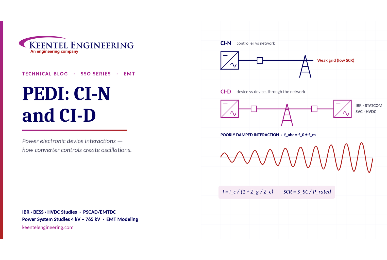
Learn power electronic device interactions (PEDI), including CI-N and CI-D, weak-grid stability, SCR, EMT studies, impedance analysis and mitigation for IBRs.
By SANDIP R PATEL
•
October 3, 2026
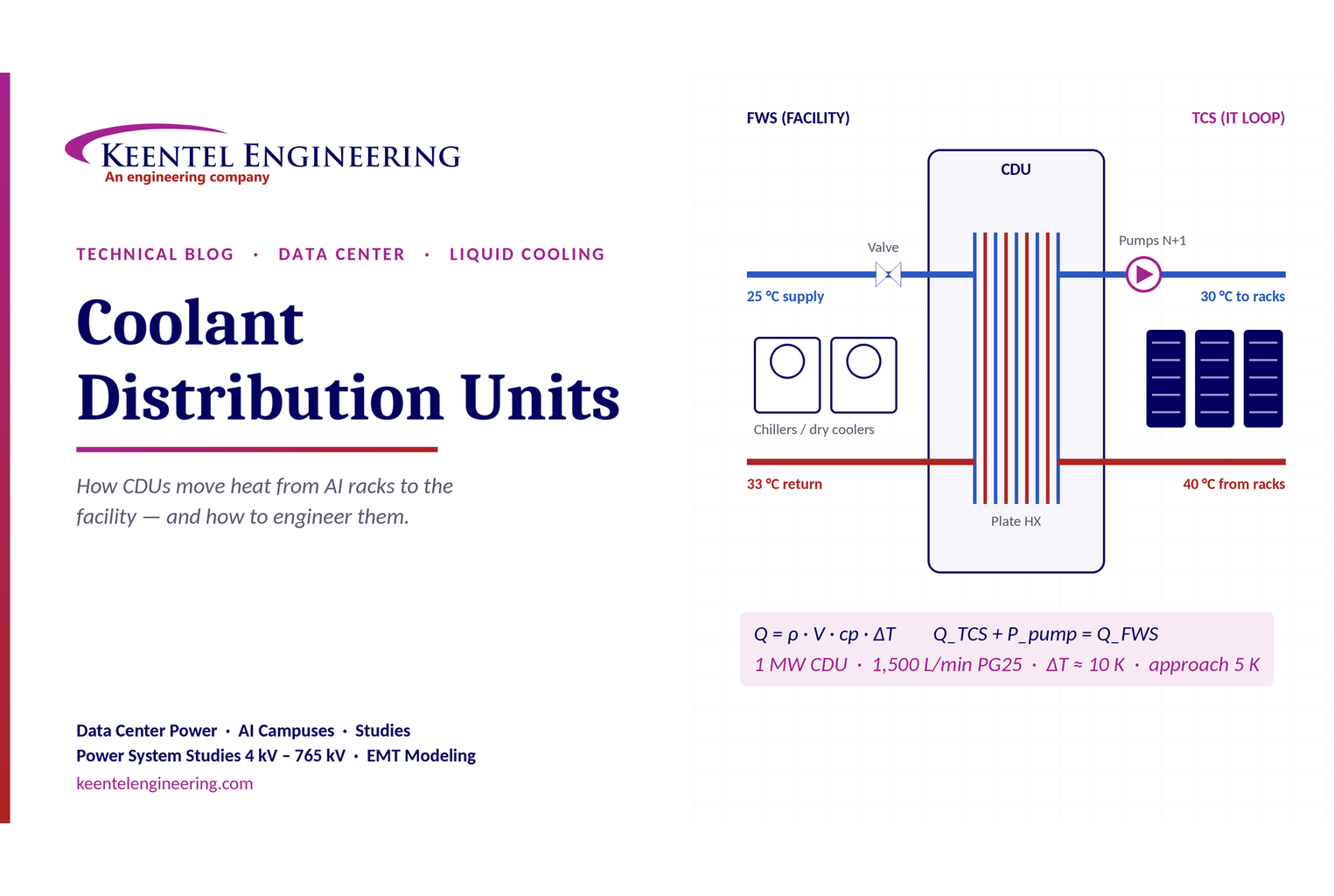
Learn how data center coolant distribution units (CDUs) work, including FWS and TCS loops, heat transfer, sizing, redundancy and liquid cooling for AI data centers.
By SANDIP R PATEL
•
October 3, 2026
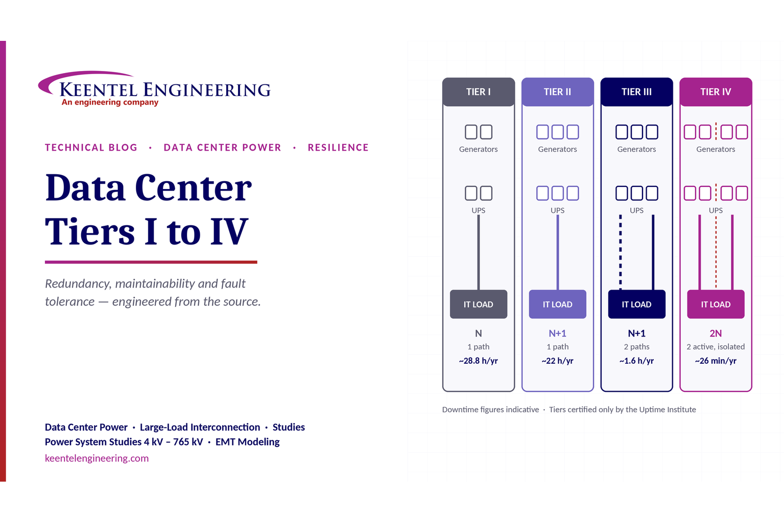
Compare Data Center Tiers I–IV, including redundancy, uptime, Tier III concurrent maintainability, Tier IV fault tolerance, UPS, generators and power design.

By SANDIP R PATEL
•
October 3, 2026
Learn how BESS supports grid stability through fast frequency response, voltage support, oscillation damping, black start, grid-forming controls and EMT studies.





