
A Coordinated Electric System Interconnection Review—the utility’s deep-dive on technical and cost impacts of your project.
Challenge: Frequent false tripping using conventional electromechanical relays
Solution: SEL-487E integration with multi-terminal differential protection and dynamic inrush restraint
Result: 90% reduction in false trips, saving over $250,000 in downtime
ERCOT enforces all of the above through simulation, which means your model is your compliance case. The bar is now high:
- Whole-facility scope. The model must represent everything the IT load, the UPS and power conversion, the cooling plant, the protection and control systems in formats compatible with ERCOT's study platforms (PSS/E, PSCAD, TSAT).
- Real control loops, not approximations. Generic textbook representations are unacceptable. The model must capture the actual inner control behavior of your power electronics.
- Hardware-validated converter models. For electronic loads, the PSCAD model must be benchmarked against actual hardware testing including voltage ride-through and subsynchronous response. A model assembled from standard PSCAD library blocks fails by definition, because a generic block has never been tested against your vendor's hardware. The good news: validation is a hardware-type test, so results for a given converter product are reusable across every facility that uses it.
- Format migration. Facilities that previously submitted the older composite load model (CMLD) format must transition to EPRI's PERC1 format.
- Three checkpoints. Models are reviewed before the stability study begins (no model, no study), before each quarterly stability assessment, and for electronic loads one final time before energization, when you must submit as-built models with a documented comparison against the previously studied data and a sworn attestation that the model matches actual field settings. ERCOT's review takes 10 business days, extendable by 20 put it on your critical path.
- A living obligation. Change your technology, controls, or relay settings in a way that affects ride-through including converting a crypto mining site to an AI data center — and you've triggered a new interconnection study, even if your megawatts don't change.
| Parameter | Detail |
|---|---|
| System | 230 kV / 138 kV transmission corridors, wind and wet-snow icing exposure |
| Data basis | 15 years of minute-resolution forced-outage records + regional weather observations |
| Core methods | Event grouping, MVA performance curves, time-to-95%-restore, area outage rate curves, fragility modeling, rerun-history benefits, exceedance and log-domain risk metrics |
| Headline result | ≈85% of maximum resilience benefit at 60% of original capital; worst-event restoration window cut from 11 days to 5 in rerun-history terms |
| Decision supported | Capital portfolio selection; resilience plan filing; post-investment verification framework |
| System / Topic | Governing Standard(s) | What It Controls |
|---|---|---|
| Overall plant electrical distribution | IEEE 141 (Red Book); IEEE 666 | Distribution architecture, voltage selection, design of generating station auxiliary service systems |
| Power system studies | IEEE 399 (Brown Book); IEEE 551 | Load flow, symmetrical/asymmetrical short circuit, motor starting methodologies down to the lowest LV panelboard |
| Protection & coordination | IEEE 242 (Buff Book); IEEE 3004.5; IEEE C37 series | Generator relaying (21, 59N, 87G), time-current coordination, selective clearing between LV and MV tiers |
| GSU / UAT / SST transformers | IEEE C57.12.00 and C57 family | Transformer ratings, impedance, testing, loading |
| HV switchyard breakers | IEEE C37.06 | AC high-voltage circuit breaker preferred ratings |
| MV switchgear (13.8 kV) | IEEE C37.20.2; IEEE C37.20.7 | Metal-clad construction, compartmentalization, vacuum breakers; arc-resistant design with plenum venting |
| MV cable | UL 1072; ICEA S-93-639 (NEMA WC 74) | Type MV-105 shielded cable, 133% insulation level for HRG systems |
| LV switchgear (480 V) | IEEE C37.13; UL 1558 | Metal-enclosed LV power circuit breaker switchgear to 635 V, draw-out ACBs with electronic trip units |
| Motor control centers | UL 845; NEMA ICS 18 | LV-MCC construction, MCCB/MCP protection for motors under ~200 HP |
| Motors | NEMA MG-1 | Motor performance, starting characteristics, service factors |
| DC & battery systems | IEEE 485; IEEE 946 | Lead-acid battery sizing (125/250 VDC), DC auxiliary system design |
| Grounding | IEEE 80; IEEE 142 (Green Book) | Ground grid step/touch potential limits; system grounding including high-resistance grounding |
| Lightning protection | IEEE 998 | Direct-stroke shielding of switchyard and outdoor generator structures |
| Arc flash & electrical safety | IEEE 1584; NFPA 70E | Incident energy calculation; worker safety boundaries and PPE |
| Fire protection | NFPA 850 | Fire protection and risk management for combustion turbine generating plants |
| Installation code | NEC (NFPA 70); NESC | Wiring methods inside the plant fence; overhead/outdoor clearances at the switchyard |
| Interconnection & compliance | FERC LGIP; NERC MOD-025/026/027, PRC-019/024/029, FAC-008 | Interconnection process, model validation, protection/ride-through coordination, facility ratings |
| IFC / Construction Deliverable | Purpose |
|---|---|
| Stamped IFC packages | Legal basis for construction; P.E. responsible charge |
| Final relay settings & TCCs | Protection as-installed matches the coordination study |
| Calculation archive | Owner records; NERC audit evidence trail |
| Commissioning procedures | Safe, sequenced energization; MOD field testing |
| Construction support | RFIs, field changes, FAT/SAT witness |
| As-builts & model handoff | Operating baseline; future study currency |
| Metric | Outcome |
|---|---|
| Defects found pre-occupancy | Three topology defects and one settings-mismatch family corrected before load migration; the shared-switchboard defect alone would have invalidated the concurrently-maintainable claim on day one |
| IST findings | Fourteen additional discrepancies surfaced under scenario testing (control logic, alarm mapping, one generator sequencing fault) — all closed before handover instead of during operations |
| Black-building test | Passed on second execution; the first attempt exposed the generator sequencing fault under true block load, exactly the failure the compressed plan would never have found |
| Handover quality | Operations team certified on the actual failure scenarios; corrected EOPs and settings documentation delivered as controlled documents |
| Business outcome | Occupancy proceeded three weeks behind the original date — against an independent estimate that the uncorrected sequencing fault carried a high probability of a full facility outage within the first year |
Part 2 — Frequently Asked Questions: Large Load Interconnection
An electric grid must remain in continuous balance — generation onto the grid must equal consumption from it at every instant. PJM achieves this balance, and prices it, through a layered market architecture. Each layer operates on a different time horizon, and each one touches project economics differently.
| Domain | Key Standards / Codes | What They Govern |
|---|---|---|
| Fire safety | NFPA 855; UL 9540 / UL 9540A | Installation requirements, separation, gas management; system safety listing and thermal-runaway fire testing |
| Grid interconnection | IEEE 1547 (distribution); IEEE 2800 (transmission IBRs) | Ride-through, reactive capability, power quality, and performance at the point of interconnection |
| Power quality | IEEE 519 | Harmonic distortion limits at the PCC |
| Protection & grounding | IEEE 80 / 81 / 142; C37 series | Grounding system design and testing; protective relaying |
| Reliability compliance | NERC standards (incl. PRC ride-through requirements) | Registered-entity obligations for grid-connected storage |
PGRR144, PSS®E Version 36, and Batch Zero: A Complete Guide to the 2025 to 2026 Transition Reshaping ERCOT Load and Generation Modeling
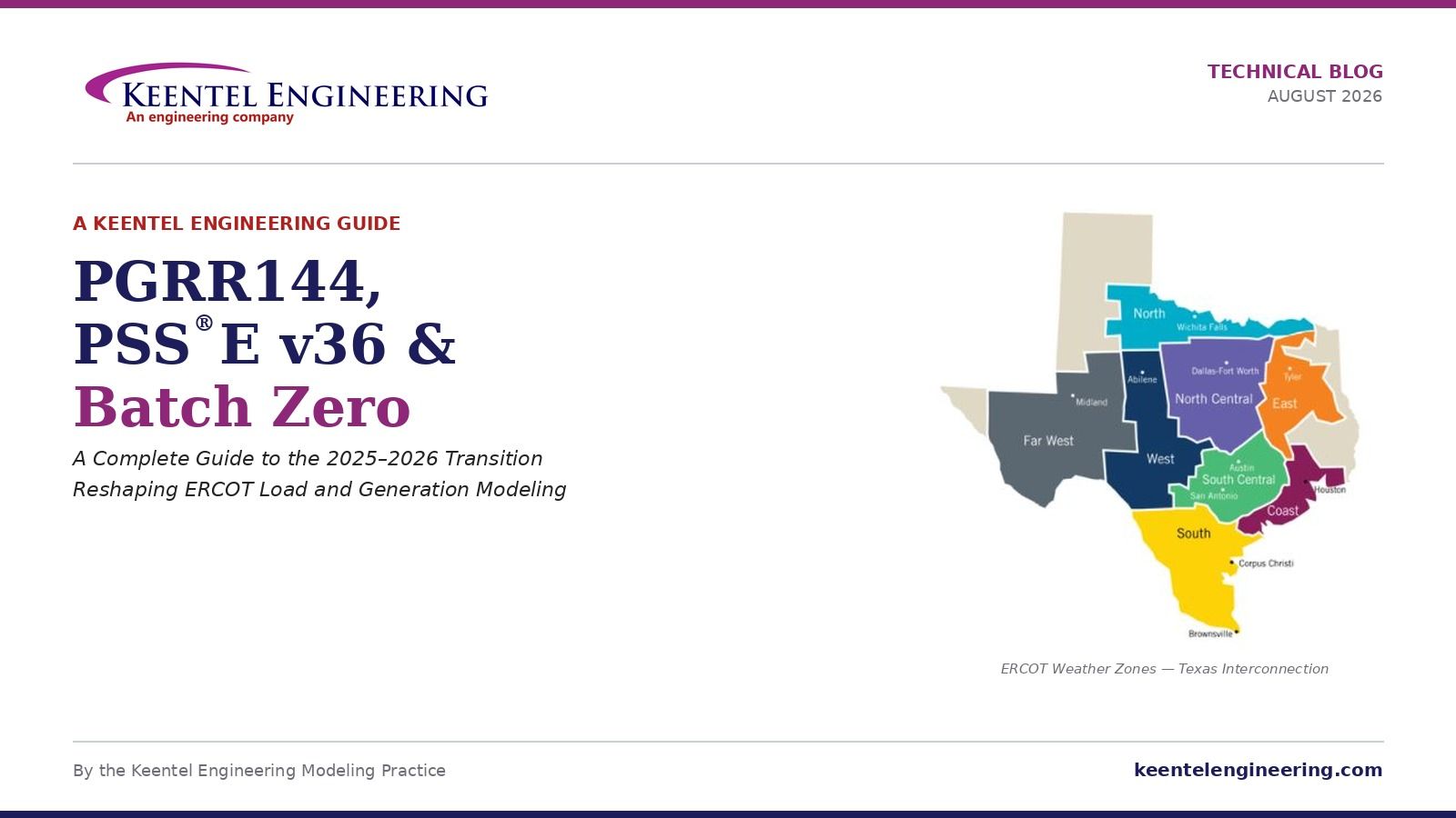
Aug 26, 2026 | Blog
By the Keentle Engineering Modeling Practice
Why This Blog Matters Right Now
If you are involved in interconnecting a data center, a battery storage project, a solar or wind farm, or any large industrial facility in the ERCOT footprint, the eighteen months between mid-2025 and late-2026 have delivered more meaningful change than any comparable stretch in the last decade. Three intersecting developments — Planning Guide Revision Request 144 (PGRR144), the mandatory transition from Siemens PSS®E version 35 to version 36, and the introduction of the Batch Zero framework for large loads under PGRR145 and NPRR1325 — have collectively rewritten what a compliant model submission looks like, who has to submit one, and how those submissions get processed.
Some of these changes have been hard deadlines. The June 1, 2026 date for PSS®E v36-compatible dynamic model submissions is one that has already passed. Some are process transformations, like the Batch Zero framework approved by the Public Utility Commission of Texas on June 18, 2026, which fundamentally changes how large-load interconnections are studied. And some are content transformations, like PGRR144's move away from composite load models toward EPRI User-Defined Models plus Composite Motor Load Dynamics representations for Large Electronic Loads.
For project developers, Interconnecting Entities, Resource Entities, and Large Load owners, the practical question is: what has actually changed, what do I have to do differently, and by when? This blog is Keentle Engineering's answer, written in the level of technical depth that project engineers and modeling consultants actually need to make decisions. We cover the regulatory context, the modeling mechanics, the OEM readiness realities, the interaction between the changes, and the schedule and cost implications. At the end, we address twelve of the questions we hear most often from clients navigating this landscape.
How to Read This BlogNew Title
The blog is organized in six substantive sections followed by a comprehensive FAQ. Each section stands alone, so if you already understand the PGRR144 framework and just need the PSS®E v36 mechanics, jump to Section 3. If you have generation experience and are learning the load-side rules for the first time, Section 2 is where to start.
- Section 1 — Setting the Stage: Why ERCOT Changed the Rules
- Section 2 — PGRR144: Formal Dynamic Modeling for Large Loads
- Section 3 — The PSS®E v35 to v36 Transition: Dates, Mechanics, OEM Readiness
- Section 4 — Batch Zero: What It Is, How It Works, and Why It Matters
- Section 5 — The Timeline: Every Date That Matters
- Section 6 — Practical Implementation: What This Means for Your Project
- Frequently Asked Questions — Twelve in-depth Q&As addressing the most common client concerns
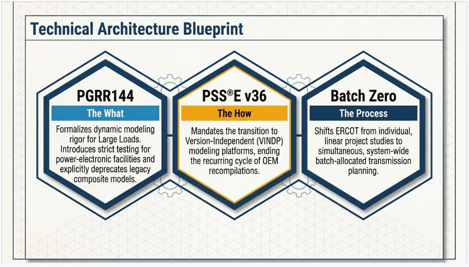
Section 1: Setting the Stage — Why ERCOT Changed the Rules
Before diving into what PGRR144, the v36 transition, and Batch Zero require, it is worth understanding why these changes happened when they did. Regulatory frameworks do not update themselves. Each of these three initiatives was driven by specific reliability concerns and specific operational realities that ERCOT could no longer address using its existing tools.
1.1 The Load Growth That Forced Everyone's Hand
ERCOT has grown accustomed to being one of the fastest-growing grids in North America, but the load additions that have appeared in the interconnection queue since 2023 are unprecedented. At the March 13, 2026 Large Load Working Group meeting, ERCOT reported that 137 new large-load interconnection requests totaling approximately 140,000 MW had been submitted and were not yet reflected in current queue charts. When those requests are included, the total large-load queue moves from around 238,000 MW to nearly 380,000 MW. To put that in context, ERCOT's all-time system peak has never exceeded approximately 85,000 MW. The queue represents multiple times the current system capacity.
Not all of that will build. ERCOT's own data indicates that the majority of interconnection requests expect to be operational by 2030, but historical attrition rates in interconnection queues are substantial. Even so, the volume is real enough — and concentrated enough in specific technology categories — that the pre-2025 project-by-project interconnection process was buckling under the load. ERCOT's original interconnection process, designed when new large-load connections were episodic industrial expansions, could not scale to hundreds of near-simultaneous data center and computational load requests.
1.2 The Reliability Concerns That Drove PGRR144
The volume of new load is one problem. The nature of that load is another. The interconnection queue is dominated by facilities whose electrical behavior is fundamentally different from the industrial and commercial loads ERCOT has traditionally served:
- Hyperscale data centers: hundreds of megawatts of power-electronic-fed IT load behind uninterruptible power supplies, with cooling loads that ramp on timescales of seconds and IT loads that can shift among data centers on timescales of minutes.
- AI training clusters: even higher power density than traditional data centers, with training workloads that can swing tens of megawatts within seconds as GPU jobs start and stop.
- Cryptocurrency mining facilities: power-electronic loads with the ability to reduce demand on operator command, which is useful for demand response but adds control-system dependencies that must be modeled.
- Electrolyzers for hydrogen production: DC-coupled loads with converter-driven behavior similar in some respects to inverter-based generation.
The traditional dynamic modeling approach for loads used composite models — ZIP-load approximations, static motor equivalents, and simplified induction motor models. These worked adequately when loads were largely resistive and motor-driven. They do not work for facilities where the dominant behavior is determined by power-electronic firmware.
ERCOT has observed real reliability events tied to this modeling gap. Multiple system disturbances since 2024 have involved large blocks of computational load tripping in response to voltage disturbances that composite load models would not have predicted. The interim Voltage Ride Through (VRT) assessment that ERCOT Operations Stability Analysis presented at the May 21, 2026 Large Load Working Group meeting identified four major large-load trip groups capable of causing tripping above 3,200 MW during severe disturbances. That is a system-shaping quantity of load that could disappear during a fault, and it was not visible in any planning study.
WHY PGRR144 EXISTS
PGRR144 is not a bureaucratic elaboration of existing rules. It is a direct response to observed reliability events. When ERCOT identified four large-load trip groups totaling more than 3,200 MW of at-risk demand, the case for formalizing dynamic modeling for the load side became overwhelming. The rule filled a modeling gap that had grown into a reliability gap.
1.3 Why the v36 Transition Happened in Parallel
The PSS®E v35 to v36 transition is not tied directly to PGRR144, but its timing is not coincidental. ERCOT relies on Siemens PTI PSS®E as the primary planning tool for the Dynamics Working Group base cases. Historically, ERCOT has stayed one full version behind the current Siemens release to avoid the disruption of forcing OEMs and consultants to recompile User-Defined Models against every new version.
Version 36, released by Siemens in 2024, introduced a feature that changed that calculus: Version Independent (VINDP) dynamic linked libraries. VINDP DLLs compiled against v36 can be used in all future versions of PSS®E without recompilation. That resolves one of the most persistent operational headaches in ERCOT's modeling ecosystem — the perennial coordination exercise of getting OEMs to release new DLLs every time PSS®E advances a version. With VINDP, the OEM compiles once against v36 and the same DLL works forever.
From ERCOT's perspective, the sooner the ecosystem transitions to v36, the sooner the version-compatibility treadmill ends. The May 2, 2025 market notice W-A050225-01 set the June 1, 2026 deadline for v36-compatible submissions, and while OEM readiness has been uneven, the direction is unambiguous. Every model built or refreshed from mid-2026 forward should be a v36 VINDP DLL.
1.4 Why Batch Zero Was the Logical Next Step
The volume challenge in Section 1.1 and the modeling challenge in Section 1.2 converge on a procedural problem: how does ERCOT actually study 140,000 MW of new interconnection requests? The traditional project-by-project approach, in which each interconnection was studied against a static system model and the transmission upgrades required were assigned to that specific project, produced two failure modes when applied at scale.
First, it generated a growing backlog. Studies took months, and the queue grew faster than studies could clear. Second, it triggered repeated restudies. A large-load interconnection studied in isolation would identify certain transmission upgrades. Six months later, a second interconnection nearby would trigger a restudy that assigned different upgrades to different projects. Neither project could commit to a cost or schedule until the interaction between them was resolved, and every additional interconnection request compounded the problem.
The Batch Zero framework, approved by PUCT on June 18, 2026 under PGRR145 and NPRR1325, addresses both failure modes by grouping qualifying loads (75 MW or greater) into a single system-wide study. Instead of studying each project against a fixed system, all qualifying projects are studied together against a jointly-planned system. The transmission upgrades needed to serve the batch as a whole are identified, and the cost of those upgrades is allocated across the batch participants.
Batch Zero is the first batch under this framework. ERCOT expects to notify Batch Zero applicants of their project classification in August 2026, and a final transmission plan covering the entire batch of projects across Texas is expected to be published in Fall 2027. Applications for Batch 1 are expected to open in Summer 2027. The batch cadence is expected to become the ongoing rhythm of large-load interconnection in ERCOT going forward.
SCHEDULE IMPLICATION FOR DEVELOPERS
The batch approach means that a large-load developer no longer controls their own study timeline in the way they once did. Batch Zero participants receive their classification and their allocated transmission upgrades on the batch's schedule, not on individual project schedules. This has substantial implications for financing, offtake negotiation, and equipment procurement. Developers used to project-by-project timelines should adjust their expectations accordingly.
Section 2: PGRR144 — Formal Dynamic Modeling for Large Loads
PGRR144 formalizes dynamic model submission, validation, and review requirements for Large Loads. It is the first ERCOT rule to treat the load side with the same modeling rigor long applied to inverter-based generation, and as of the July 2026 ROS meeting the proposed language was approved and PGRR144 was progressing through the ERCOT stakeholder process toward final effectiveness.
2.1 What PGRR144 Actually Covers
The rule applies to Large Loads at or above 75 MW, with escalating requirements based on how much power-electronic content the load contains. Three broad categories emerge from the rule text and from ERCOT's Large Load Working Group discussions:
| Category | Definition | Dynamic Model Rigor |
|---|---|---|
| Large Load (LL) | Any load ≥ 75 MW that materially affects grid stability | PSS®E dynamic model required; MQT required; VRT testing (informational unless NOGRR282 applies) |
| Large Electronic Load (LEL) | Large Load where power-electronic content dominates behavior (data centers, crypto mines, electrolyzers) | Full PSS®E + PSCAD + TSAT model set; NOGRR282-aligned VRT pass/fail; Converter Model Validation required |
| Large Computational Load (LCL) | LEL subject to workload variation (AI training, general-purpose data center compute) | All LEL requirements plus power variation testing against the 10 MW peak-to-peak per 5-second limit |
The three-category structure matters because it determines the size of the modeling deliverable a developer is on the hook for. A conventional industrial load at 100 MW may fall into the LL category and require a comparatively straightforward composite-model-plus-MQT submission. A 250 MW hyperscale data center with GPU training racks will fall into the LCL category and require the full six-artifact submission described in Section 6.1 of this blog. The difference in modeling effort is roughly an order of magnitude.
2.2 The Deprecation of Composite Load Models for LELs
The single most consequential technical change in PGRR144 is that composite load models are explicitly deprecated for Large Electronic Loads. This is not a soft recommendation; ERCOT has been direct at the Large Load Working Group that composite representations will not be accepted as the primary dynamic model for LELs. The rationale reflects everything we know about power-electronic load behavior.
A composite load model — the standard ZIP plus induction motor representation — assumes that when voltage drops, the load's active power draw drops in a mathematically well-behaved way, and the induction motor component may stall or trip based on stall protection curves. For an inverter-fed UPS driving computational load, none of that behavior applies. The UPS rectifier isolates the DC bus from AC voltage disturbances until either the UPS ride-through envelope is exceeded (triggering an inverter output shutdown to protect the DC bus) or the AC voltage recovers within the ride-through window. The tripping is binary: full load one millisecond, zero load the next.
PGRR144 requires that this binary tripping behavior — the actual physics of what happens at a data center during a voltage disturbance — be represented in the model. That is what the EPRI User-Defined Model framework provides, and it is why PGRR144 recommends the EPRI UDM in combination with a Composite Motor Load Dynamics (CMLD) representation for the cooling motor portion of the facility.
THE CORE MODEL ARCHITECTURE FOR LELs
For LELs, the model is not a static motor equivalent with a slightly modified stall curve. It is a two-part representation combining an EPRI User-Defined Model for the power-electronic UPS-fed load with a Composite Motor Load Dynamics model for the induction motors that drive chillers, cooling towers, and computer-room air handlers. This is a genuine departure from prior practice, and it requires modeling skill that most load-side project teams have never needed to develop.
2.3 The Converter Model Validation (CMV) Exercise
PGRR144 introduces a new artifact called the Converter Model Validation report, applicable specifically to LELs. It is a hardware-benchmark exercise, analogous in spirit to the Unit Model Validation report long required for inverter-based generation. The purpose is to demonstrate that the submitted PSCAD model accurately reflects the physical converter behavior under voltage disturbances and in the sub-synchronous frequency range where computational-load switching can drive real reliability issues.
Practically, the CMV requires:
- Bench-test measurement of the UPS converter response to a defined set of voltage disturbances, typically obtained from the UPS OEM.
- Small-signal frequency sweep measurement over the 5 to 55 Hz range, which is the sub-synchronous band where computational-load switching interactions are known to occur.
- PSCAD simulation of the same disturbances and frequency sweeps.
- Side-by-side comparison of the measured versus simulated response, with documented explanations for any residual differences.
- A summary attestation from a qualified engineer confirming the PSCAD model represents the physical converter within acceptable tolerances.
The CMV is the point in the PGRR144 submission workflow where OEM cooperation is most critical. UPS vendors have historically not been asked to provide dynamic model documentation of this depth, and most UPS OEMs are still building out the internal capability to support CMV requests. Developers should not wait until the modeling phase to raise this with their UPS vendor — the CMV should be a contract requirement negotiated at UPS purchase, not an afterthought.
2.4 The Voltage Ride Through (VRT) Dimension and NOGRR282
PGRR144 does not stand alone. It coordinates with Nodal Operating Guide Revision Request 282 (NOGRR282), which establishes voltage ride-through obligations for Large Loads. Where NOGRR282 applies, the PSS®E and PSCAD models submitted under PGRR144 must explicitly demonstrate ride-through capability across the NOGRR282 envelope, and the test results are pass/fail: a failure means the load cannot interconnect on the terms proposed.
For loads not subject to NOGRR282 compliance, voltage disturbance testing under PGRR144 is still performed — but the results are informational rather than pass/fail. This distinction matters. At the April 23, 2026 LLWG meeting, ERCOT explicitly clarified that voltage disturbance testing under PGRR144 for non-NOGRR282 loads is intended only to validate dynamic model performance under disturbance conditions, not to impose new compliance requirements. The point is to build ERCOT's understanding of aggregated load behavior, not to disqualify individual projects.
Even in the informational case, Keentle Engineering recommends the full VRT test catalog. Operational reality will inevitably subject the facility to voltage disturbances, and the informational test results become the baseline against which future firmware or configuration changes are compared. A well-documented pre-operation VRT baseline saves substantial trouble the first time a real disturbance produces an unexpected load response.
2.5 The Large Computational Load (LCL) Power Variation Limit
PGRR144 introduces a specific limit on active power variation for Large Computational Loads: 10 megawatts peak-to-peak measured over a rolling five-second interval. At the June 19, 2026 LLWG meeting, ERCOT presented proposed evaluation language focusing on oscillatory frequency components between 0.1 Hz and 55 Hz, capturing both inter-area and sub-synchronous oscillations.
The limit exists because computational workloads — particularly AI training workloads that run tens of thousands of GPUs in synchronized training cycles — can produce coordinated power draw swings of a magnitude and frequency that can interact adversely with the transmission system's inertia and damping characteristics. A single 200 MW GPU cluster starting or stopping a training batch is not a grid problem. Fifty synchronized 200 MW clusters cycling at a resonant frequency of the surrounding transmission network is a grid problem, and it is exactly the sort of emerging behavior that ERCOT is trying to get ahead of.
For developers, the practical implication is that the workload management system for the facility must respect the 10 MW / 5-second limit, and the model must demonstrate that respect. Keentle Engineering has developed workflow-simulation harnesses that verify this compliance during the MQT phase, so that any workload management defects are caught during modeling rather than during operation.
LCL COMPLIANCE IS A FACILITY-LEVEL OBLIGATION
The 10 MW / 5-second LCL power variation limit is enforced at the facility level, not the rack level or the individual training cluster level. If your data center has multiple training clusters that can synchronize their workload starts and stops, the aggregate synchronized behavior is what matters. Workload orchestration systems that treat training clusters independently, without an aggregate rate-of-change limit, will not demonstrate LCL compliance no matter how well-behaved each cluster is in isolation.
2.6 The Load Information Form (LIF)
Alongside the technical models, PGRR144 requires a fully populated Load Information Form. The LIF is the load-side analog of the generation-side data submissions that Resource Entities have long provided. It documents:
- Facility electrical characteristics: total load, breakdown of power-electronic vs. motor content, on-site generation if any.
- Tables A, B, and C: protection settings, ride-through behavior parameters, and interconnection point electrical data.
- Survey Questions 39 through 50: UPS operating modes, backup power switching sequence, on-site generation dispatch philosophy during grid events, demand-side management participation, and computational-load transfer capability to off-ERCOT infrastructure.
The LIF is more than a bureaucratic checklist. ERCOT uses the LIF responses to build assumptions about how the facility will behave operationally, and those assumptions feed forward into both the dynamic modeling and the transmission planning studies. LIFs that are hand-waved through — with 'to be determined' entries or placeholder values — produce dynamic models that carry those uncertainties forward, and produce reviewer questions that must be resolved before the submission can be accepted.
Keentle Engineering's LIF workflow starts with a facility characterization workshop that produces documented answers to the survey questions before any modeling work begins. This front-loads the coordination overhead with the UPS vendor, cooling equipment vendor, and workload management team, so that modeling proceeds on solid assumptions rather than on placeholders that must be revisited.
Section 3: The PSS®E v35 to v36 Transition — Dates, Mechanics, and OEM Readiness
The PSS®E v36 transition is the most concrete of the three changes covered in this blog. It has a specific market notice, a specific deadline, and a specific technical mechanism that resolves a long-standing pain point in the ERCOT modeling ecosystem. It is also the change that has produced the most confusion, because OEM readiness has been uneven and the deadline has already passed.
3.1 The Market Notice and the Deadline
On May 2, 2025, ERCOT issued market notice W-A050225-01: 'Requirement to submit dynamic models compatible with PSS®E version 36 prior to June 1, 2026.' The notice was unambiguous in its language. Interconnecting Entities and Resource Entities were required to submit dynamic models fully compatible with PSS®E version 36 prior to June 1, 2026, so that ERCOT could complete its transition of Dynamics Working Group base cases to v36.
The deadline has passed. As of the June 2026 IBRWG and RIWG meetings, ERCOT confirmed that entities with outstanding v36 submissions should coordinate directly with ERCOT to close remaining gaps. The rule was firm in principle, but ERCOT has recognized the practical dependency on OEM DLL availability and is working through gaps case-by-case rather than blocking projects wholesale.
THE DEADLINE HAS PASSED — HERE'S WHAT THAT MEANS
The June 1, 2026 deadline was a milestone, not a guillotine. ERCOT is closing gaps case-by-case for entities whose OEMs are still working on v36 DLL delivery. But this flexibility is not a substitute for action — if your project has outstanding v36 obligations, engage ERCOT proactively and document the OEM release schedule you are depending on.
3.2 What Version 36 Actually Delivers: Version Independent DLLs
The reason ERCOT prioritized the transition to v36 — over any of the intermediate versions Siemens has released — is a single feature: Version Independent (VINDP) dynamic linked libraries. Understanding VINDP is essential to understanding why the transition matters and why the effort of a one-time re-compile is worth it.
Historically, when Siemens released a new major version of PSS®E, existing UDMs stopped working. The OEM had to recompile the DLL against the new version's development kit, redistribute it to modeling consultants and asset owners, and coordinate with each ISO or utility that used the model. This produced a recurring version-compatibility cycle that consumed OEM engineering time and created windows during which certain models were simply not available on certain platforms.
Version 36 changes this by introducing a formal API layer between the UDM code and the PSS®E internal data structures. UDMs compiled against v36 access PSS®E bus voltage, model CON parameters, ICON values, and other internal data through a documented set of Python-based pssdm APIs — the COMON4.INS common block that older UDMs used is no longer accessible from v36 onwards. In exchange for this abstraction layer, VINDP DLLs compiled against v36 will run in all future versions of PSS®E without recompilation. The version-compatibility treadmill ends.
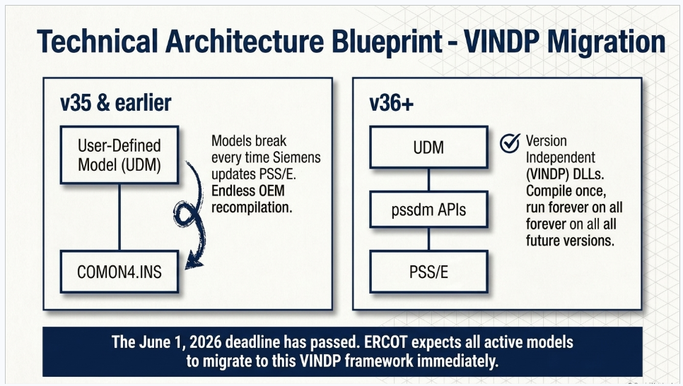
| v35 UDM Behavior | v36 VINDP UDM Behavior |
|---|---|
| Direct access to PSS®E data via COMON4.INS | Access via documented pssdm APIs |
| Recompile required for each PSS®E major version | Compile once, forward-compatible with all future versions |
| OEM release lag typically 6-12 months per version | OEM release cycle decoupled from PSS®E version cycle |
| Model behavior can drift between versions | Consistent behavior guaranteed across versions |
3.3 Converting Existing UDMs to VINDP
Siemens provides a Python-based UDM converter as part of the Environment Manager (EM) version 10.0 and higher. The converter automates most of the mechanical transformation from COMON4.INS-based UDM source code to the VINDP API form. For most OEMs, running the converter is a relatively straightforward exercise; the trickier work is in the edge cases where UDM code depended on specific data structures that do not map cleanly to the API.
Once the source code is in VINDP form, the OEM compiles it against v36 to produce the new DLL. The resulting DLL can be used in v36 and all future versions of PSS®E without further recompilation. Keentle Engineering has coordinated dozens of these conversions on behalf of clients and has developed diagnostic procedures for the recurring failure modes: undocumented common-block accesses, model initialization code that assumed specific memory layout, and protection models that used raw pointer arithmetic instead of PSS®E's abstraction layer.
3.4 OEM Readiness as of Mid-2026
The transition is only useful to the extent that OEMs have released v36-compatible DLLs. ERCOT has publicly tracked OEM readiness at working group meetings, and as of the June 2026 IBRWG and RIWG meetings the status was:
| OEM | PSS®E v36 DLL Status | Practical Implication for Developers |
|---|---|---|
| Tesla | Complete | Ready for full v36 submissions |
| Siemens Gamesa | Complete | Ready for full v36 submissions |
| SMA | Complete | Ready for full v36 submissions |
| Power Electronics | Complete | Ready for full v36 submissions |
| Ingeteam | Complete | Ready for full v36 submissions |
| EPC | Complete | Ready for full v36 submissions |
| GE | Partially complete | Coordinate with GE on specific product lines |
| Vestas | Outstanding | Engage ERCOT with OEM release schedule |
| Sungrow | Outstanding | Engage ERCOT with OEM release schedule |
This status snapshot will age quickly. Developers should confirm current OEM readiness with their equipment vendor directly rather than relying on point-in-time summaries. The key operational point is that ERCOT's flexibility on the June 1 deadline is calibrated to OEM readiness, not to developer preference. If your OEM has released a v36 DLL and you have not submitted, ERCOT expects you to submit. If your OEM has not released a v36 DLL, ERCOT is working through the gap with you — but that flexibility is provisional and requires documented engagement.
3.5 What You Have to Do Differently for v36 Submissions
The mechanics of a v36 submission are similar to a v35 submission with a small number of important differences:
- Model files: v36 UDM DLL compiled as VINDP, plus the associated .raw or .sav case file, .dyr dynamics file, and Excel Dynamic Model Template.
- File naming: Keentle Engineering recommends including 'v36' in the zip filename to distinguish v36 packages from any legacy v35 files that may still be in circulation. Our convention is (SITECODE)_DYNAMIC_v36_(YYYY-MM-DD).zip.
- RIOO-RS subject line: ERCOT has requested that entities include 'v36' in the submission subject line to help prioritize reviews during the transition window.
- MQT report: A Model Quality Test report must accompany the v36 submission per Planning Guide Section 6.2(5)(c). Simply recompiling a DLL and resubmitting without an MQT overlay is insufficient. If both v35 and v36 models are submitted (which may be required during the base-case transition), the MQT should overlay both versions on the same axes to confirm consistent response.
- PSCAD models: The v36 transition is a PSS/E-specific change. PSCAD models are not affected, but reviewers will expect the combined PSS/E-PSCAD-TSAT overlay plot to use the v36 PSS/E model.
3.6 Grid-Forming Models and the v36 Timing
One important nuance in the v36 transition concerns grid-forming (GFM) inverter models used in Advanced Grid Support ESR (AGS-ESR) submissions. There are no grid-forming generic models available in PSS/E v35 — the v35 standard library predates GFM standardization. ERCOT has allowed temporary flexibility around v35 UDM use for AGS-ESR FIS and additional studies where a v35 UDM is the only available representation of the equipment. But the expectation is that as v36 GFM generic models mature, submissions will migrate to those generics or to v36 UDMs, with reasonable correspondence between v35 UDM response and later v36 generic model response.
For AGS-ESR developers, the practical guidance is to build the FIS-stage submission using whatever combination of v35 UDM and v36 v36-compatible UDM is available at the time, but to plan explicitly for a re-submission to v36 GFM generic or v36 UDM as the ecosystem matures. Keentle Engineering has structured multiple AGS-ESR engagements as two-phase modeling projects for exactly this reason.
Section 4: Batch Zero — What It Is, How It Works, and Why It Matters
Batch Zero is the third leg of the 2025 to 2026 transition. Where PGRR144 changes what a Large Load has to submit and the v36 transition changes what tool the submission runs on, Batch Zero changes how ERCOT processes the submission and produces the transmission plan around it. It is a structural reform of the large-load interconnection process, and it addresses the scaling problem that the pre-2025 process could no longer manage.
4.1 The Approval and the Framework
The Batch Zero framework was formally approved by the Public Utility Commission of Texas on June 18, 2026, through two coordinated ERCOT revision requests: NPRR1325 (which modifies the Nodal Protocols to define the batch process) and PGRR145 (which aligns the Planning Guide to support batch studies). PGRR145 should not be confused with PGRR144 — the former is the batch framework, the latter is the dynamic modeling framework. The two rules were developed in parallel and are complementary: PGRR144 defines what each large load must submit, and PGRR145 defines how ERCOT will study the resulting submissions in coordinated batches.
The batch framework applies to loads at or above 75 MW. Loads below that threshold continue to interconnect through the traditional process. Above the threshold, qualifying loads are grouped into a single system-wide batch study rather than being studied one at a time. Batch Zero is the first batch under this framework and covers loads that submitted qualifying interconnection requests by the batch cutoff date.
4.2 The Batch Zero Timeline
| Milestone | Date |
|---|---|
| PUCT approves Batch Zero framework (NPRR1325 and PGRR145) | June 18, 2026 |
| ERCOT notifies Batch Zero applicants of their project classification | August 2026 |
| Batch Zero full scope becomes known | August 2026 (following classification notices) |
| Final transmission plan covering Batch Zero projects published | Fall 2027 |
| Applications for Batch 1 expected to open | Summer 2027 |
| Majority of Batch Zero projects expected to be operational (per ERCOT interconnection queue analysis) | By 2030 |
The August 2026 classification notices are the near-term milestone that developers should be watching. Classification determines which projects are formally included in Batch Zero and what their category is within the batch. This has direct implications for financing conversations, offtake negotiations, and equipment procurement timelines. Developers who submitted qualifying requests before the batch cutoff should be preparing internally for classification notice receipt and the follow-on modeling coordination that classification triggers.
4.3 How Batch Studies Actually Work
The mechanical difference between a batch study and a project-by-project study is worth understanding in detail, because it changes the assumptions every developer should be making about their project's schedule and cost allocation.
In a project-by-project study, each interconnection request was studied against a base system model that reflected the status quo plus previously-committed transmission upgrades. The study identified the additional upgrades required to accommodate the specific project, and those upgrades were assigned to the project as its cost responsibility. If a second, nearby project submitted an interconnection request during the study period, the interaction between the two projects could not be evaluated without a restudy — and restudies were common enough that project schedules became unpredictable.
In a batch study, all qualifying projects within the batch are studied simultaneously against a base system that reflects the status quo. The study identifies the transmission upgrades required to accommodate the entire batch — not project by project — and those upgrades are allocated across the batch participants using a defined methodology. Individual projects do not receive individual upgrade assignments; they receive a share of the batch-wide upgrade plan.
THE DEVELOPER MENTAL MODEL HAS TO CHANGE
This is a fundamental change in how developers should think about their project. You no longer control your interconnection timeline as a solo actor. Your project's classification, transmission upgrade allocation, and operational date are functions of the batch as a whole. This has substantial implications for how you negotiate with lenders, offtakers, and equipment vendors — none of whom are accustomed to interconnection schedules being tied to a batch cadence.
4.4 The Interaction Between Batch Zero and PGRR144
Batch Zero and PGRR144 do not exist in isolation. Every Large Load in Batch Zero must satisfy PGRR144's dynamic modeling requirements to be studied in the batch. If the model submission is incomplete or non-compliant, the project cannot be evaluated in the batch study — and there is no mechanism to defer that project to Batch 1 without restarting the interconnection request. Modeling compliance is a prerequisite for batch participation, not something that can be addressed after the batch study is complete.
At the July 2026 ERCOT TAC meeting, ERCOT clarified that the PGRR144 process will include Model Quality Testing (MQT) to validate submitted Large Load models and assess compliance with applicable NOGRR282 requirements as part of the batch study workflow. Actual operational performance verification will be performed once PMU data becomes available at the operational facility. This creates a two-stage validation chain: pre-operational validation through MQT and CMV as part of the batch study, and post-operational validation through PMU data comparison after energization.
For developers, the immediate implication is that PGRR144 compliance is time-critical. Batch Zero classification is expected in August 2026, and the final transmission plan is expected in Fall 2027. That gives developers roughly twelve to fifteen months to complete their PGRR144 model submissions in a form that can be evaluated in the batch study. Facilities that treat modeling as a downstream activity — something to be worked out once the project is 'real' — will find themselves outside the batch study timeline and losing their place in the queue.
4.5 The Queue Diversity Insight
One of the most important observations from the LLWG meetings in 2026 is that the interconnection queue and the actual coincident load are very different quantities. At the April 23, 2026 LLWG meeting, ERCOT noted that approximately 9 GW of large load was approved to energize but that the observed non-simultaneous monthly peak consumption was approximately 4 GW, with a simultaneous peak of approximately 3.7 GW in March 2026. In other words, the actual coincident large-load draw was less than half of the approved-to-energize quantity, reflecting diversity in usage patterns across facilities.
This matters for developers because it informs how ERCOT thinks about batch study assumptions. The system does not need to be planned for every large load to be at 100 percent utilization simultaneously — that scenario is not physically realistic. But it also means that ERCOT is scrutinizing load profiles, workload diversity, and coincidence assumptions during the batch study. A developer whose load profile assumes 100 percent utilization 24/7 will face different treatment than one whose profile reflects realistic diurnal and workload-driven variation.
The Load Information Form is the primary place where this profile information is documented, which is one more reason why the LIF cannot be treated as a paperwork exercise. The survey responses about workload management, demand-side management participation, and computational-load transfer capability directly feed the coincidence assumptions ERCOT uses in the batch study.
4.6 What Happens After Batch Zero
Applications for Batch 1 are expected to open in Summer 2027. The precise cadence of subsequent batches has not been formally set, but the general expectation is that batches will occur on an annual or semi-annual basis, cycling through submission windows, study periods, transmission planning, and final approval on a repeatable schedule. Developers whose projects miss Batch Zero can plan for Batch 1, but the timing of study completion and transmission plan finalization will follow the batch schedule, not the project's individual schedule.
The batch cadence has second-order implications for OEM procurement and equipment lead times.
Data center inverters, UPS units, and computational hardware often have twelve to eighteen month lead times, and the interaction between order-to-delivery timing and the batch study timing can be tight. Keentle Engineering has begun helping clients with integrated schedule planning that reconciles the batch study calendar with equipment procurement calendars — a coordination problem that did not really exist in the pre-batch era.
Section 5: The Timeline — Every Date That Matters
Because these three initiatives overlap in time and interact in effect, a consolidated timeline is one of the most useful tools for developers trying to understand where they are in the process. The timeline below captures the dates that have already occurred and the dates that are upcoming as of the writing of this blog in August 2026.
5.1 Historical Timeline of the Key Events
| Date | Event |
|---|---|
| May 2, 2025 | ERCOT issues market notice W-A050225-01 setting the June 1, 2026 deadline for PSS®E v36-compatible model submissions |
| Throughout 2025 | Siemens releases PSS®E v36 with Version Independent (VINDP) DLL capability and Python-based UDM converter in Environment Manager v10.0+ |
| Throughout 2025 - early 2026 | PGRR144 language development in the Large Load Working Group; multiple iterations of proposed dynamic modeling requirements |
| December 2025 | ERCOT LEL Modeling Approach presentation clarifies EPRI UDM v4 recommendation for LEL representation |
| March 13, 2026 | LLWG meeting reports large-load queue growth from ~238,000 MW to ~380,000 MW with 137 new requests totaling 140,000 MW |
| April 23, 2026 | LLWG meeting reviews PGRR144 clarifications on VRT testing scope for non-NOGRR282 loads; ERCOT emphasizes informational-only status for those cases |
| May 21, 2026 | LLWG meeting reviews final interim VRT assessment; identifies four major large-load trip groups totaling >3,200 MW of at-risk demand |
| June 1, 2026 | PSS®E v36 mandatory submission deadline |
| June 18, 2026 | PUCT approves Batch Zero framework via NPRR1325 and PGRR145 |
| June 19, 2026 | LLWG meeting; PGRR144 progressing toward July ROS vote; LCL power variation limit language finalized at 10 MW peak-to-peak over 5-second rolling window |
| July 2026 | ROS approves proposed language for PGRR144 – Dynamic Model Submission and Review Requirements for Large Loads including LCLs |
| July 2026 (TAC discussion) | ERCOT clarifies that PGRR144 process will include MQT to validate submitted Large Load models; operational verification via PMU data post-energization |
5.2 Forward-Looking Timeline
| Expected Date | Event |
|---|---|
| August 2026 | ERCOT notifies Batch Zero applicants of their project classification |
| Late 2026 - 2027 | Batch Zero study execution; PGRR144 model submissions required from all batch participants |
| Summer 2027 | Applications for Batch 1 expected to open |
| Fall 2027 | Final transmission plan covering all Batch Zero projects expected to be published |
| 2027 - 2028 | Ongoing v36 base case build-out; residual v35 UDM re-compilations resolved case-by-case |
| By 2030 | Majority of Batch Zero projects expected to be operational per ERCOT queue analysis |
Two dates in this timeline deserve particular attention. The August 2026 Batch Zero classification notice is the near-term operational trigger for many developers — until classification is received, projects cannot fully plan their modeling submission timelines. And the Fall 2027 transmission plan publication is the point at which Batch Zero developers will know the actual transmission upgrade allocation for their projects, which drives cost, timeline, and financing conversations.
5.3 Where You Are on This Timeline Determines What You Do Next
The single most useful diagnostic question for a developer is: where does my project sit on this timeline? The answer determines what actions are most valuable right now.
| Your Position | What Matters Most Right Now |
|---|---|
| Generation project with completed v35 submission, v36 recompile outstanding | Coordinate with OEM on VINDP recompile; engage ERCOT with documented release schedule |
| Generation project with v36 submission complete | Focus on MQT overlay updates, verification report refresh; standard ongoing compliance |
| Large Load project awaiting Batch Zero classification | Begin PGRR144 modeling preparation now; don't wait for classification notice to start |
| Large Load project not yet in Batch Zero | Plan for Batch 1 submission window (Summer 2027); understand PGRR144 requirements before applying |
| Existing operational Large Load considering modification | Understand PGRR144 modification thresholds before any planned firmware or configuration change |
| New AGS-ESR / grid-forming project | Two-phase modeling plan: v35 UDM for FIS, migration to v36 GFM generic or v36 UDM as ecosystem matures |
Section 6: Practical Implementation — What This Means for Your Project
Regulatory frameworks are only useful to the extent that project teams can translate them into concrete workstreams. This section addresses the practical implementation of PGRR144 and the v36 transition for the two main developer types this blog is written for: Large Load developers navigating PGRR144 for the first time, and Resource Entities managing the v36 transition on an existing generation portfolio.
6.1 The Six-Artifact PGRR144 Submission for a Large Electronic Load
A PGRR144 submission for a Large Electronic Load is not a single document. It is a coordinated package of six artifacts that must be internally consistent and cross-referenced. In Keentle Engineering's practice, the six artifacts are:
- PSS®E v36 dynamic model — built using EPRI UDM v4 for the power-electronic UPS/IT load portion, combined with a Composite Motor Load Dynamics (CMLD) representation for the cooling motor load. Compiled as a Version Independent (VINDP) DLL. Includes the full model package: .raw or .sav case file, .dyr dynamics file, .dll for the UDM, Excel Dynamic Model Template, and Python initialization scripts for switched shunts and transformer taps if any are present.
- PSCAD electromagnetic transient model — detailed converter representation embedded in the ERCOT PSCAD Template. Not built from PSCAD master library standard blocks; instead built from UPS OEM source-code-based converter models where available, or from a documented equivalent representation validated through the Converter Model Validation exercise. Includes the completed PSCAD Guideline Checksheet.
- TSAT model — required where the PSS®E submission uses a UDM. Includes bus-number and equipment-name variants with 100 percent identical results across formats, plus .raw, .dyr, .dll, .tudm files and associated .mon, .dat, and .swi files.
- Model Quality Test report — combined overlay plot of PSS/E, PSCAD, and TSAT responses on the same axes for each required test scenario. Test scenarios include flat-start initialization, voltage disturbance testing per NOGRR282 envelope where applicable, sub-synchronous response testing over 5-55 Hz, and — for LCLs — power variation testing against the 10 MW peak-to-peak per 5-second limit.
- Converter Model Validation (CMV) report — hardware-benchmark exercise comparing the PSCAD model against actual UPS converter measurements. Requires OEM cooperation for bench-test data. Documents any residual differences between measured and simulated response with engineering explanations.
- Load Information Form (LIF) — fully populated with Tables A, B, and C for facility electrical characteristics, protection settings, and interconnection point data, plus Survey Questions 39 through 50 addressing UPS operating modes, on-site generation dispatch philosophy, demand-side management participation, and computational-load transfer capability.
Missing any one of the six artifacts triggers a rejection or an incomplete-submission finding. The order of assembly matters as well: the LIF should be finalized first because it drives assumptions used in the models, the CMV depends on OEM bench-test data that has long lead times, and the MQT overlay depends on all three model platforms being consistent with each other.
6.2 The v36 Migration for an Existing Generation Portfolio
For a Resource Entity managing a fleet of existing generation projects, the v36 migration is a fundamentally different exercise. The models exist; the question is how to update them efficiently. Keentle Engineering's fleet migration workflow proceeds in five stages:
- Portfolio inventory — catalog every dynamic model currently on file with ERCOT for every site in the portfolio. Identify which are UDMs (requiring OEM recompilation), which are standard library models (which automatically transition to v36), and which are legacy models that may need updating for other reasons.
- OEM coordination — for every UDM in the inventory, identify the OEM and current v36 release status. For OEMs that have released v36 VINDP DLLs, request the DLL and any updated documentation. For OEMs still working on v36 releases, obtain a documented release schedule and share it with ERCOT to preserve deadline flexibility.
- Recompilation and testing — receive the v36 VINDP DLL from each OEM, integrate it into the site model, and run the DMVIEW MQT catalog to confirm consistent response with the pre-migration v35 model. Any material response differences require OEM engagement to resolve before the submission proceeds.
- MQT overlay preparation — build combined MQT reports overlaying v35 and v36 PSS/E responses (plus PSCAD and TSAT for IBRs) on the same axes for each required test scenario. Document any acceptable differences and explain their source.
- RIOO-RS submission — assemble the submission package with (SITECODE)_DYNAMIC_v36_(YYYY-MM-DD).zip and (SITECODE)_PSCAD_(YYYY-MM-DD).zip naming, include 'v36' in the submission subject line, and upload as an Attachment-Only Change Request. Coordinate with the TSP on the change notification.
Portfolio-wide v36 migrations typically complete in six to twelve weeks depending on OEM responsiveness. The bottleneck is almost always OEM coordination, not the modeling work itself. Fleet operators that have not begun this exercise should start immediately — the June 1, 2026 deadline has passed and ERCOT's case-by-case flexibility is not indefinite.
6.3 Schedule and Cost Realities
Both PGRR144 and the v36 transition involve real time and cost. Directional ranges from Keentle Engineering's experience across dozens of engagements:
| Project Type | Typical Duration | Typical Cost Range |
|---|---|---|
| First-of-kind LEL PGRR144 submission (hyperscale data center) | 14-22 weeks | Mid six figures USD |
| Follow-on LEL PGRR144 submission (same UPS platform) | 10-14 weeks | Low six figures USD |
| Standard Large Load (non-LEL) PGRR144 submission | 8-12 weeks | High five figures USD |
| Single-site v36 UDM re-compile and MQT overlay | 2-4 weeks | Low five figures USD |
| Portfolio v36 migration (10+ sites) | 6-12 weeks | Discounted retainer basis |
| AGS-ESR two-phase modeling (v35 UDM then v36 GFM) | 16-24 weeks total | Mid to high six figures USD |
These ranges assume reasonable OEM cooperation and no unexpected model defects. Real-world engagements can compress or extend based on OEM responsiveness, the maturity of the client's existing documentation, and the complexity of the facility architecture. The single largest cost driver, particularly for first-of-kind LEL projects, is the coordination overhead of aligning the ERCOT reviewer, the UPS OEM, the cooling equipment vendor, and the developer's workload management team on consistent modeling assumptions.
6.4 Common First-Time Developer Mistakes
Because the load-side developer community is largely new to ERCOT dynamic modeling, several failure patterns recur. Keentle Engineering has observed each of these in the field:
- Treating the LIF as paperwork. The LIF drives dynamic model assumptions and batch study coincidence factors. Placeholder responses produce placeholder-quality studies.
- Not negotiating CMV support at UPS purchase. Retrofitting a Converter Model Validation obligation onto an existing UPS supply agreement is difficult and expensive; building it into the original purchase is straightforward.
- Assuming composite models will suffice. Composite load models are explicitly deprecated for LELs under PGRR144. Attempting to submit one triggers a rejection and a full re-do.
- Underestimating the OEM coordination timeline. UPS vendors and cooling equipment vendors have historically not been asked to support ERCOT-style modeling. Their internal capability is uneven and their response times are longer than IBR OEMs.
- Sequencing modeling after equipment procurement. The modeling process reveals design-basis constraints that can inform equipment specification. Doing modeling in parallel with equipment specification produces better outcomes than doing it after equipment is ordered.
- Missing the Batch Zero preparation window. Batch Zero classification arrives in August 2026; modeling for the batch study needs to be underway before that. Waiting for classification to begin modeling loses months of runway.
Frequently Asked Questions
PGRR144 is a Planning Guide Revision Request that formalizes dynamic model submission, validation, and review requirements for Large Loads in ERCOT. It applies to any load at or above 75 MW that materially affects grid stability. It applies with the most rigor to Large Electronic Loads (LELs) — data centers, cryptocurrency mines, and other power-electronics-dominated facilities — and with additional requirements to Large Computational Loads (LCLs), which include AI training clusters and general-purpose data center compute.
If your project is a Large Load at 75 MW or above, PGRR144 applies. If your project is dominantly power-electronic in nature — meaning UPS-fed IT load, GPU compute, cryptocurrency ASIC racks, or electrolyzer conversion equipment — you are almost certainly in the LEL category and probably the LCL category. That means the full six-artifact PGRR144 submission (PSS/E model, PSCAD model, TSAT model, MQT report, Converter Model Validation report, and Load Information Form) applies to you.
PGRR144 does not apply to loads below 75 MW under current thresholds, and traditional industrial loads at or above 75 MW that are not power-electronic-dominated will typically fall into the less rigorous Large Load category rather than the LEL category. If you are uncertain which category your facility falls into, a facility characterization workshop is the standard first step — and Keentle Engineering offers no-commitment scoping calls for exactly this purpose.
The deadline has passed but ERCOT is applying it as a milestone, not a guillotine. The correct interpretation depends on the source of any outstanding v36 obligation for your project:
- If your OEM has released a v36 VINDP DLL and you simply have not submitted, ERCOT expects you to submit. The window of automatic flexibility has closed for OEMs that have completed their v36 releases (Tesla, Siemens Gamesa, SMA, Power Electronics, Ingeteam, EPC).
- If your OEM has not released a v36 DLL — Vestas and Sungrow are outstanding as of mid-2026, and GE is partially complete — engage ERCOT proactively with a documented OEM release schedule. ERCOT is working through these gaps case-by-case rather than blocking projects, but the flexibility is provisional and requires you to be actively engaged, not passively waiting.
- If your project uses standard library models (not UDMs), the transition is largely automatic — the standard library moves to v36 without your intervention. Verify with your consultant that the intended library models are available in v36.
- If your project uses grid-forming models (AGS-ESR), the situation is more nuanced. There are no GFM generic models in PSS/E v35, so ERCOT has allowed temporary flexibility around v35 UDM use for AGS-ESR FIS studies. Plan for eventual migration to v36 GFM generics or v36 UDMs as those become available.
The strategic advice is to prioritize the VINDP-compiled v36 UDM immediately regardless of the deadline pressure. The one-time cost of recompilation is small compared to the recurring cost of maintaining parallel v35 and v36 builds through future ERCOT case cycles. Keentle Engineering can typically close a portfolio-wide v35-to-v36 migration in six to twelve weeks.
VINDP is a feature introduced in PSS/E version 36 that allows a User-Defined Model DLL to run in v36 and all future versions of PSS/E without recompilation. The technical mechanism is a formal API layer (the pssdm APIs) between the UDM code and the PSS/E internal data structures, replacing the COMON4.INS common block that older UDMs used to access data directly. In exchange for going through the API abstraction, VINDP DLLs are decoupled from PSS/E's internal implementation details and therefore forward-compatible.
It matters because it ends the version-compatibility treadmill that has consumed OEM engineering time and created recurring project schedule risk for the last decade. Historically, every time Siemens released a major new PSS/E version, every OEM with UDMs on file had to recompile against the new version, redistribute the updated DLLs to consultants and asset owners, and coordinate with each ISO that used the model. This took months per version and created windows during which certain models were not available on certain platforms.
With VINDP, that cycle ends. The OEM compiles once against v36 and the same DLL works in all future PSS/E versions. For fleet owners with dozens of sites using multiple OEM DLLs, this is a substantial reduction in ongoing coordination overhead. For OEMs, it reduces the internal engineering resource needed to maintain ERCOT compatibility. For ERCOT, it removes a recurring source of base-case build delays.
The one-time cost is the initial VINDP conversion of existing UDM code, which Siemens provides tooling for via the Environment Manager v10.0+ Python-based UDM converter. Most conversions run cleanly; the edge cases are UDMs that depended on undocumented common-block accesses or that used raw pointer arithmetic against PSS/E's internal memory layout. Keentle Engineering has developed diagnostic procedures for these edge cases and coordinates the conversion with OEMs on client behalf.
A PGRR144 submission for a Large Electronic Load like a hyperscale data center comprises six coordinated artifacts. First, a PSS/E v36 dynamic model using EPRI UDM v4 for the UPS/IT load portion combined with a Composite Motor Load Dynamics (CMLD) representation for the cooling motor load. Second, a PSCAD electromagnetic transient model of the converter interface embedded in the ERCOT PSCAD Template. Third, a TSAT model if the PSS/E submission uses a UDM. Fourth, a Model Quality Test report demonstrating flat-start initialization, voltage disturbance ride-through per NOGRR282, sub-synchronous response, and (for LCLs) power variation compliance. Fifth, a Converter Model Validation (CMV) report benchmarking the PSCAD model against actual UPS hardware measurements. Sixth, a fully populated Load Information Form documenting facility characteristics and Survey Questions 39 through 50.
The order of preparation matters. The LIF is typically the first artifact completed because it establishes the assumptions the models are built on. The CMV depends on OEM bench-test data that has the longest lead time, so it should be scoped and started early. The MQT is the last artifact assembled because it depends on all three model platforms being consistent with each other.
The largest scope surprise for first-time load-side developers is the sheer size of this artifact set. Traditional load interconnection projects submitted a fraction of what PGRR144 now requires. A first-of-kind LEL submission typically takes 14 to 22 weeks and can cost into the mid six figures. Follow-on submissions using the same UPS platform run 10 to 14 weeks and are less expensive because the CMV framework and EPRI UDM configuration can be reused.
The two rules are complementary but distinct. PGRR144 defines what a Large Load has to submit in terms of dynamic models — the technical content of the submission. PGRR145 defines how ERCOT will study the resulting submissions — the process by which Large Loads are grouped into batches and studied collectively rather than one at a time. PGRR145 is the Planning Guide component of the Batch Zero framework, and it works alongside NPRR1325, which modifies the Nodal Protocols to support the batch process.
Both were developed and approved on overlapping timelines. PGRR145 and NPRR1325 were formally approved by PUCT on June 18, 2026, establishing the Batch Zero framework. PGRR144 progressed through the ERCOT stakeholder process on a slightly different track, receiving proposed language approval at the July 2026 ROS meeting.
In practical terms, they are two rules addressing two parts of the same problem. PGRR144 addresses the question 'What must a Large Load submit for us to be able to study it?' PGRR145 addresses the question 'How do we efficiently study hundreds of Large Load submissions at once?' A developer subject to Batch Zero will encounter both rules — PGRR144 governs the modeling deliverable and PGRR145 governs the batch study process the deliverable feeds into.
Because they do not capture the actual physics of what happens at a Large Electronic Load during a voltage disturbance. A composite load model represents the load as a combination of constant-impedance, constant-current, and constant-power components (the 'ZIP' representation) plus an induction motor component with stall protection curves. That representation was developed for and works reasonably well for traditional industrial loads dominated by direct-connected motors and resistive components.
It does not represent the behavior of a UPS-fed IT load. A UPS rectifier isolates the DC bus from AC voltage disturbances until either the UPS ride-through envelope is exceeded — triggering an inverter output shutdown to protect the DC bus — or the AC voltage recovers within the ride-through window. The tripping behavior is binary: full load one millisecond, zero load the next. A ZIP-plus-induction-motor composite model cannot represent that binary behavior no matter how carefully its parameters are tuned.
The consequence of using a composite model for an LEL is that system studies miss the load-tripping behavior that has actually caused multiple reliability events in ERCOT. When Operations Stability Analysis presented at the May 21, 2026 LLWG meeting that four major large-load trip groups had been identified totaling more than 3,200 MW of at-risk demand, that number could not have been generated using composite models — it required the load-side dynamic modeling framework that PGRR144 formalizes.
The replacement architecture, EPRI UDM plus CMLD, addresses the composite-model gap. The EPRI UDM represents the UPS-fed IT load with an inverter-based-generation-quality level of detail, including the DC bus dynamics, the ride-through logic, and the trip-and-reconnect behavior that composite models miss. The CMLD component handles the cooling-motor load that does behave more traditionally. Together, the two-part representation reflects how the physical facility actually responds.
The limit is a maximum on how much the active power draw of a Large Computational Load can vary over any rolling five-second window. Peak-to-peak means the difference between the highest and lowest instantaneous power draw within the window, and the 10 MW threshold applies to the entire facility, not to individual training clusters or racks. At the June 19, 2026 LLWG meeting, ERCOT clarified that the evaluation focuses on oscillatory frequency components between 0.1 Hz and 55 Hz, which captures both inter-area electromechanical oscillations and sub-synchronous control-loop oscillations.
The limit exists because coordinated computational workloads — particularly AI training that synchronizes tens of thousands of GPUs across a facility — can produce aggregate power draw swings that are large enough and cyclic enough to excite grid resonances. A single 200 MW GPU cluster starting and stopping a training batch is not a grid problem. Fifty synchronized 200 MW clusters cycling at a resonant frequency of the surrounding transmission network is a grid problem. The 10 MW / 5-second limit prevents that class of interaction by capping the aggregate rate of change.
Compliance is a facility-level obligation, not a rack-level or cluster-level obligation. That means the workload management system for the facility must respect the aggregate limit even when many individual workloads would violate it in isolation. Practically, this requires an orchestration layer that monitors aggregate facility power draw and modulates the timing of workload starts and stops to keep the peak-to-peak variation within limits.
Keentle Engineering demonstrates compliance during the MQT phase using a workflow simulation harness that mimics realistic workload patterns and verifies that the aggregate power draw remains within the 10 MW / 5-second envelope across all tested scenarios. Any workload management defects are caught during modeling rather than during operational compliance monitoring. The MQT results become part of the PGRR144 submission and, later, the baseline against which post-operational PMU measurements are compared.
The most fundamental change is that you no longer control your own interconnection study timeline. Under the project-by-project process, your project was studied on its own schedule against a fixed system model, and the transmission upgrades required were assigned to your project. Under Batch Zero and its successors, your project is studied as part of a batch, on the batch's schedule, against a base system that reflects all other batch participants simultaneously. Your project's classification, transmission upgrade allocation, and operational date are functions of the batch as a whole.
This has downstream implications for how you negotiate with lenders, offtakers, and equipment vendors. Financing conversations that assumed you could commit to a specific in-service date once you had ERCOT approval need to be restructured around the batch timeline. Offtake agreements with specific commercial-operation-date obligations need flexibility to accommodate batch study delays that are not within your control. Equipment vendors with twelve to eighteen month lead times need to be engaged with an understanding that the exact energization date will be determined by batch schedule rather than project schedule.
The Batch Zero timeline is: PUCT approval on June 18, 2026; classification notices in August 2026; final transmission plan in Fall 2027; majority of projects operational by 2030. Applications for Batch 1 open in Summer 2027 for projects that did not make Batch Zero or that entered the queue after the Batch Zero cutoff. The cadence going forward is expected to be annual or semi-annual batches, so a developer whose project misses one batch can plan for the next, but not on an arbitrary schedule.
The most immediate action for a developer with a project in Batch Zero is to prepare the PGRR144 modeling submission now, before classification arrives. Waiting for the classification notice to start modeling loses months of runway and increases the risk that the model will not be ready in time to be evaluated in the batch study. Keentle Engineering has been engaging Batch Zero applicants throughout 2026 to prepare their submissions in parallel with the classification process.
For a Large Electronic Load, no, PSS/E alone is not enough. PGRR144 requires PSCAD models for LELs, and the Converter Model Validation exercise requires PSCAD specifically because it is the platform where the electromagnetic transient behavior of the UPS converter can be honestly represented and benchmarked against hardware measurements. PSS/E is a positive-sequence stability tool. It represents the network in per-phase averaged form and integrates on timescales of milliseconds. That level of abstraction works for large-scale system stability studies but does not capture the microsecond-scale behavior of a switching converter.
PSCAD, by contrast, is an electromagnetic transient simulator that represents the network in full three-phase detail and integrates at time steps of 10 to 20 microseconds. It models the UPS converter switching either explicitly with IGBT-level representations or through documented voltage-source equivalents. This level of detail is what allows the ride-through logic, the DC bus dynamics, and the sub-synchronous response of a UPS-fed load to be represented faithfully.
For non-LEL Large Loads — traditional industrial facilities at or above 75 MW that are not power-electronic-dominated — PSCAD is not required under PGRR144. A PSS/E model with an MQT and a Load Information Form is sufficient for that category. But for any facility whose behavior is determined by power electronics rather than by motors and resistive elements, PSCAD is part of the deliverable and not optional.
The cost implication is real. PSCAD modeling represents 40 to 60 percent of the total modeling labor for a first-of-kind LEL project, largely because of the coordination overhead with the UPS OEM for the Converter Model Validation exercise. Developers who understand this from the start budget appropriately. Developers who discover it partway through a project face schedule pressure and cost overruns.
Keentle Engineering has observed several failure patterns across first-time PGRR144 engagements. The recurring mistakes are:
- Treating the Load Information Form as paperwork. The LIF drives dynamic model assumptions and Batch Zero coincidence factors. Placeholder responses produce placeholder-quality studies. Complete the LIF thoughtfully before modeling starts, not as an afterthought at submission time.
- Not negotiating Converter Model Validation support at UPS purchase. Retrofitting a CMV obligation onto an existing UPS supply agreement is difficult and expensive. Building CMV into the original purchase — as a documented contractual requirement — is straightforward and inexpensive. This is a one-time procurement decision with substantial downstream cost implications.
- Assuming composite load models will suffice. Composite representations are explicitly deprecated for LELs under PGRR144. Attempting to submit one produces immediate rejection and a full re-do. The EPRI UDM plus CMLD architecture is the required approach for LELs.
- Underestimating the OEM coordination timeline. UPS vendors and cooling equipment vendors have historically not been asked to support ERCOT-style modeling. Their internal capability is uneven and their response times are longer than IBR OEMs. Build 6 to 10 weeks of OEM coordination time into any first-of-kind LEL project schedule.
- Sequencing modeling after equipment procurement. The modeling process reveals design-basis constraints that can inform equipment specification. Doing modeling in parallel with equipment specification produces better outcomes than doing it after equipment is ordered. Modeling should start when the facility concept is 60 to 80 percent defined, not after final equipment orders.
- Missing the Batch Zero preparation window. Batch Zero classification arrives in August 2026; PGRR144 modeling for batch study evaluation needs to be underway before that. Waiting for classification to begin modeling loses months of runway.
- Confusing PGRR144 with PGRR145. They are two separate rules addressing complementary parts of the same challenge. PGRR144 is about what you submit; PGRR145 is about how ERCOT studies it in batches. You need to comply with both, but they operate on different tracks.
Each of these mistakes is preventable with an early-engagement discipline. Keentle Engineering's practice is to conduct a facility characterization workshop before any modeling work begins, precisely to surface and address these issues while they are still cheap to resolve.
PGRR144 defines the dynamic modeling requirements. NOGRR282 defines the voltage ride-through performance requirements. The two rules are complementary: PGRR144 tells you what model you have to submit, and NOGRR282 tells you what performance the model has to demonstrate.
Where NOGRR282 applies, the voltage ride-through test in the PGRR144 Model Quality Test is pass/fail. The submitted PSS/E and PSCAD models must explicitly demonstrate ride-through capability across the NOGRR282 voltage envelope. A failure means the load cannot interconnect on the terms proposed — either the facility design has to change to meet the ride-through requirement, or the interconnection request has to be modified.
Where NOGRR282 does not apply — for certain load categories or configurations excluded from the ride-through obligation — voltage disturbance testing under PGRR144 is still performed, but the results are informational rather than pass/fail. ERCOT clarified at the April 23, 2026 LLWG meeting that this informational testing is intended to validate dynamic model performance under disturbance conditions, not to impose new compliance requirements on non-NOGRR282 loads. The point is to build ERCOT's aggregate understanding of load behavior, not to disqualify individual projects.
Even for non-NOGRR282 loads, Keentle Engineering recommends completing the full VRT test catalog. Operational reality will inevitably subject the facility to voltage disturbances, and the informational test results become the baseline against which future firmware or configuration changes are compared. A well-documented pre-operation VRT baseline saves substantial trouble the first time a real disturbance produces an unexpected load response and everyone starts asking whether it was in the model.
Keentle Engineering's experience across LEL engagements suggests that a first-of-kind hyperscale data center or comparable LEL project typically requires 14 to 22 weeks of modeling effort from initial facility characterization through ERCOT submission. Total cost lands in the mid six figures USD depending on facility scale, complexity of the workload profile, and OEM cooperation. Follow-on submissions using the same UPS platform run 10 to 14 weeks and are less expensive because the EPRI UDM configuration, CMV framework, and workload compliance harness can be reused.
The dominant timeline driver is OEM coordination for the Converter Model Validation. UPS vendors have historically not been asked to provide dynamic model documentation of the depth CMV requires, and most vendors are still building out the internal capability. Depending on the vendor, obtaining bench-test measurements for the CMV exercise can take four to eight weeks — which is why Keentle Engineering typically starts the CMV coordination in parallel with the facility characterization phase rather than waiting until later.
The dominant cost driver is whether the project is truly first-of-kind or whether it benefits from prior Keentle work with the same equipment. Our practice maintains reusable frameworks for common UPS platforms, workload management architectures, and cooling equipment configurations. Where a project fits into an existing framework, both cost and timeline compress substantially. Where a project requires a genuinely new modeling architecture — a novel UPS technology, an unusual cooling arrangement, an unprecedented workload profile — the first-of-kind premium applies.
Beyond the direct modeling cost, developers should budget for coordination time with their UPS vendor (contract amendment or clarification), cooling equipment vendor (motor load characterization), and workload management team (aggregate power variation compliance). These are internal costs to the developer's organization rather than external consulting fees, but they are real time commitments that need to be planned for.
Keentle Engineering offers no-commitment scoping calls for developers considering their first PGRR144 engagement. The scoping call typically takes 60 to 90 minutes and produces a directional cost and timeline estimate specific to the project's characteristics. Contact us at contact\@keentelengineering.com to schedule.
Closing Thoughts
The eighteen-month window between mid-2025 and late-2026 has reshaped the ERCOT modeling landscape more than any comparable period in recent memory. PGRR144 has extended the dynamic modeling discipline that has long governed inverter-based generation to the Large Load side of the grid, filling a reliability gap that had produced real operational events. The PSS®E v36 transition has resolved a decade-long version-compatibility treadmill through the introduction of Version Independent DLLs. And Batch Zero has restructured the large-load interconnection process to handle the unprecedented queue growth that no per-project workflow could scale to.
For developers and operators navigating this landscape, the practical takeaway is that the level of modeling discipline required for successful ERCOT interconnection has stepped up significantly, and the coordination overhead across OEMs, ERCOT reviewers, and internal project teams has grown accordingly. The organizations that will succeed in this environment are the ones that treat modeling as an integrated project workstream from the beginning, not as a compliance afterthought at the end.
Keentle Engineering has built its practice around exactly this integrated approach. We work with Resource Entities, Interconnecting Entities, Large Load developers, OEMs, and asset managers to deliver dynamic models, MQT reports, verification reports, PSCAD Converter Model Validations, and Batch Zero submission packages that meet ERCOT's rigor on first review. Our team combines deep simulation expertise across PSS/E, TSAT, and PSCAD with practical knowledge of the ERCOT Planning Guide, Nodal Operating Guide, PGRR144, PGRR145, and the ongoing v36 transition.
If you are working on a project affected by any of the changes discussed in this blog, we invite you to reach out for a no-commitment scoping conversation. Whether you are managing an existing generation portfolio through the v36 migration or preparing a first-of-kind LEL submission for Batch Zero, our team is structured to support engagements ranging from single targeted consultations through multi-year modeling program management.

About the Author:
Sandip "Sonny" R. Patel, P.E.
IEEE Senior Member · Founder & CEO, Keentel Engineering
In 1995, Sonny Patel earned his Electrical Engineering degree from the University of Illinois. But degrees don't build legacies — action does.
For three decades, he has worked the power industry from every side of the table: 16 years as a utility engineer at Exelon/Commonwealth Edison; generation leadership across hydroelectric, industrial steam turbine, and a 9 GW renewable fleet; NERC Regional Entity Senior Compliance Engineer and Audit Team Lead, auditing some of the nation's largest utilities; and testing and commissioning lead on equipment up to 765 kV — the very top of the North American grid.Utility. Generator. Regulator. Consultant. Few engineers have seen all four seats. Fewer still have sat in them.
His experience spans nuclear, hydro, conventional generation, renewables, oil and gas, mining — and today's data centers, where he is authoring a three-book series on data center design. He is a Licensed Professional Engineer in six states and a Licensed Electrical Contractor in Florida (Unlimited EC) — he doesn't just design the work; he's qualified to stand behind its execution.Today, as Founder and CEO of Keentel Engineering, Sonny leads a nationwide team of engineers delivering substation design, power system studies, NERC compliance, and commissioning — done right, coast to coast.Three decades. Every side of the table. One standard: accountable engineering.
Services

Let's Discuss Your Project
Let's book a call to discuss your electrical engineering project that we can help you with.
About the Author:
Sandip "Sonny" R. Patel, P.E.
IEEE Senior Member · Founder & CEO, Keentel Engineering
In 1995, Sonny Patel earned his Electrical Engineering degree from the University of Illinois. But degrees don't build legacies — action does.
For three decades, he has worked the power industry from every side of the table: 16 years as a utility engineer at Exelon/Commonwealth Edison; generation leadership across hydroelectric, industrial steam turbine, and a 9 GW renewable fleet; NERC Regional Entity Senior Compliance Engineer and Audit Team Lead, auditing some of the nation's largest utilities; and testing and commissioning lead on equipment up to 765 kV — the very top of the North American grid.
Utility. Generator. Regulator. Consultant. Few engineers have seen all four seats. Fewer still have sat in them.
His experience spans nuclear, hydro, conventional generation, renewables, oil and gas, mining — and today's data centers, where he is authoring a three-book series on data center design. He is a Licensed Professional Engineer in six states and a Licensed Electrical Contractor in Florida (Unlimited EC) — he doesn't just design the work; he's qualified to stand behind its execution.
Today, as Founder and CEO of Keentel Engineering, Sonny leads a nationwide team of engineers delivering substation design, power system studies, NERC compliance, and commissioning — done right, coast to coast.Three decades. Every side of the table. One standard: accountable engineering.
Leave a Comment
Thank you for contacting us.
We will get back to you as soon as possible.
We will get back to you as soon as possible.
Oops, there was an error sending your message.
Please try again later.
Please try again later.
Related Posts

By SANDIP R PATEL
•
October 3, 2026
Engineering guide to PRC-028 disturbance recording, PRC-029 ride-through and PRC-030 event detection for inverter-based resources.

By SANDIP R PATEL
•
October 3, 2026
A practical guide to SSO classification, SSR, PEDI, Wind-SSCI, EMT analysis, mitigation and protection based on CIGRE TB 909.

By SANDIP R PATEL
•
October 3, 2026
Learn ERCOT generator testing for PFR, MOD-025 and MOD-026/027, including staged tests, capability verification, dynamic models and field testing.

By SANDIP R PATEL
•
October 3, 2026
Learn how PV string I-V curve testing identifies hidden solar performance losses, including soiling, shading, mismatch, degradation, and wiring faults.

By SANDIP R PATEL
•
October 3, 2026
Learn how active harmonic filters work, how to size AHF systems, reduce VFD harmonics, calculate losses, and meet IEEE 519 TDD limits at the PCC.
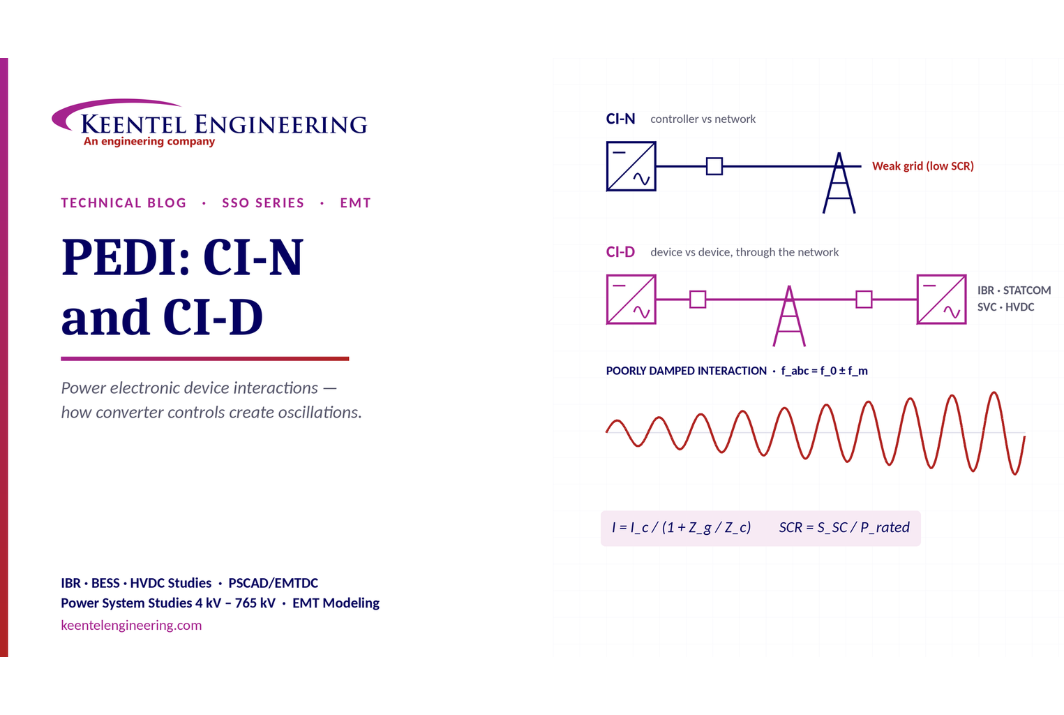
By SANDIP R PATEL
•
October 3, 2026
Learn power electronic device interactions (PEDI), including CI-N and CI-D, weak-grid stability, SCR, EMT studies, impedance analysis and mitigation for IBRs.
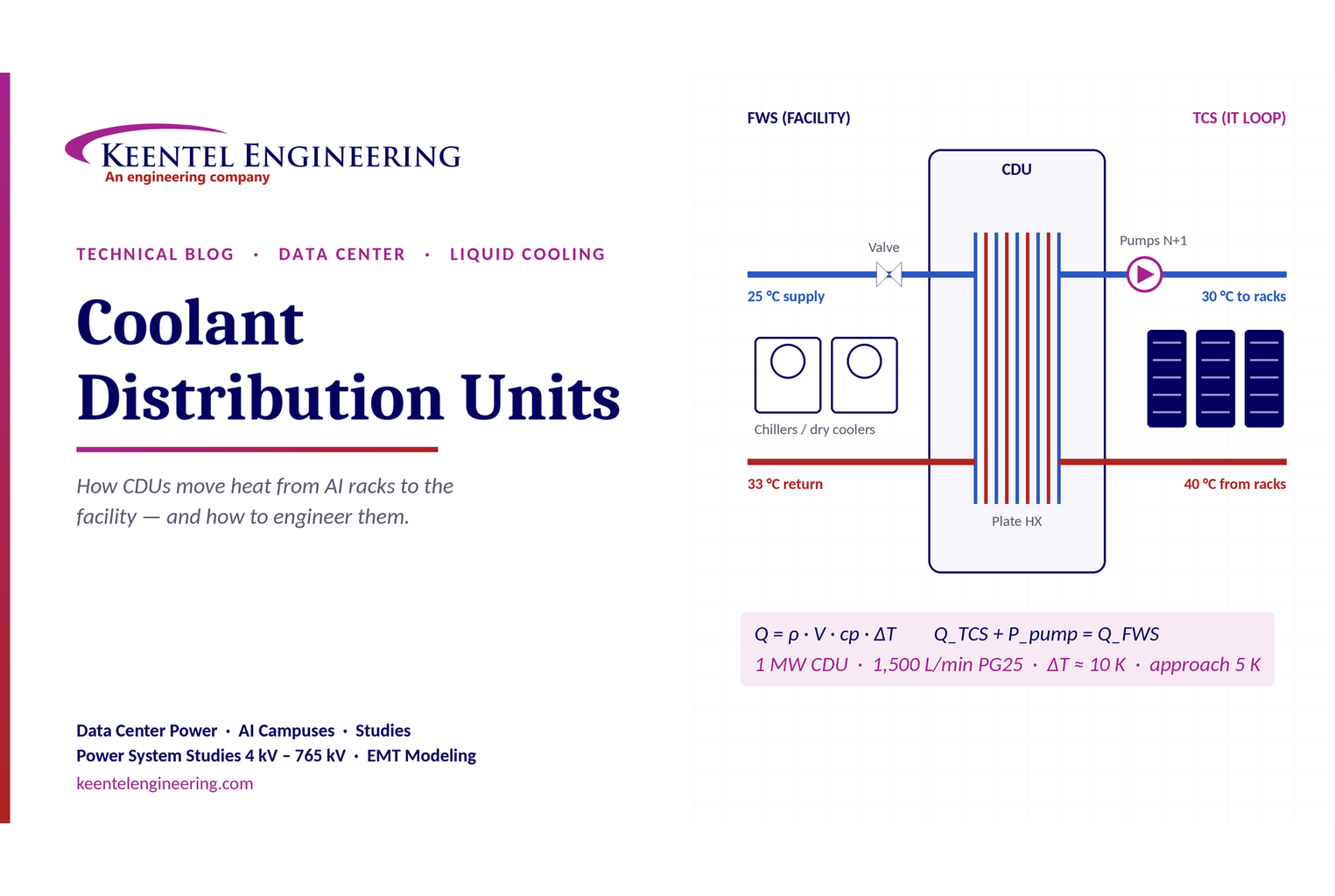
By SANDIP R PATEL
•
October 3, 2026
Learn how data center coolant distribution units (CDUs) work, including FWS and TCS loops, heat transfer, sizing, redundancy and liquid cooling for AI data centers.
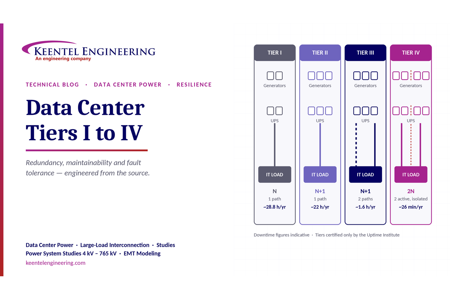
By SANDIP R PATEL
•
October 3, 2026
Compare Data Center Tiers I–IV, including redundancy, uptime, Tier III concurrent maintainability, Tier IV fault tolerance, UPS, generators and power design.

By SANDIP R PATEL
•
October 3, 2026
Learn how BESS supports grid stability through fast frequency response, voltage support, oscillation damping, black start, grid-forming controls and EMT studies.





