
A Coordinated Electric System Interconnection Review—the utility’s deep-dive on technical and cost impacts of your project.
Challenge: Frequent false tripping using conventional electromechanical relays
Solution: SEL-487E integration with multi-terminal differential protection and dynamic inrush restraint
Result: 90% reduction in false trips, saving over $250,000 in downtime
ERCOT enforces all of the above through simulation, which means your model is your compliance case. The bar is now high:
- Whole-facility scope. The model must represent everything the IT load, the UPS and power conversion, the cooling plant, the protection and control systems in formats compatible with ERCOT's study platforms (PSS/E, PSCAD, TSAT).
- Real control loops, not approximations. Generic textbook representations are unacceptable. The model must capture the actual inner control behavior of your power electronics.
- Hardware-validated converter models. For electronic loads, the PSCAD model must be benchmarked against actual hardware testing including voltage ride-through and subsynchronous response. A model assembled from standard PSCAD library blocks fails by definition, because a generic block has never been tested against your vendor's hardware. The good news: validation is a hardware-type test, so results for a given converter product are reusable across every facility that uses it.
- Format migration. Facilities that previously submitted the older composite load model (CMLD) format must transition to EPRI's PERC1 format.
- Three checkpoints. Models are reviewed before the stability study begins (no model, no study), before each quarterly stability assessment, and for electronic loads one final time before energization, when you must submit as-built models with a documented comparison against the previously studied data and a sworn attestation that the model matches actual field settings. ERCOT's review takes 10 business days, extendable by 20 put it on your critical path.
- A living obligation. Change your technology, controls, or relay settings in a way that affects ride-through including converting a crypto mining site to an AI data center — and you've triggered a new interconnection study, even if your megawatts don't change.
| Parameter | Detail |
|---|---|
| System | 230 kV / 138 kV transmission corridors, wind and wet-snow icing exposure |
| Data basis | 15 years of minute-resolution forced-outage records + regional weather observations |
| Core methods | Event grouping, MVA performance curves, time-to-95%-restore, area outage rate curves, fragility modeling, rerun-history benefits, exceedance and log-domain risk metrics |
| Headline result | ≈85% of maximum resilience benefit at 60% of original capital; worst-event restoration window cut from 11 days to 5 in rerun-history terms |
| Decision supported | Capital portfolio selection; resilience plan filing; post-investment verification framework |
| System / Topic | Governing Standard(s) | What It Controls |
|---|---|---|
| Overall plant electrical distribution | IEEE 141 (Red Book); IEEE 666 | Distribution architecture, voltage selection, design of generating station auxiliary service systems |
| Power system studies | IEEE 399 (Brown Book); IEEE 551 | Load flow, symmetrical/asymmetrical short circuit, motor starting methodologies down to the lowest LV panelboard |
| Protection & coordination | IEEE 242 (Buff Book); IEEE 3004.5; IEEE C37 series | Generator relaying (21, 59N, 87G), time-current coordination, selective clearing between LV and MV tiers |
| GSU / UAT / SST transformers | IEEE C57.12.00 and C57 family | Transformer ratings, impedance, testing, loading |
| HV switchyard breakers | IEEE C37.06 | AC high-voltage circuit breaker preferred ratings |
| MV switchgear (13.8 kV) | IEEE C37.20.2; IEEE C37.20.7 | Metal-clad construction, compartmentalization, vacuum breakers; arc-resistant design with plenum venting |
| MV cable | UL 1072; ICEA S-93-639 (NEMA WC 74) | Type MV-105 shielded cable, 133% insulation level for HRG systems |
| LV switchgear (480 V) | IEEE C37.13; UL 1558 | Metal-enclosed LV power circuit breaker switchgear to 635 V, draw-out ACBs with electronic trip units |
| Motor control centers | UL 845; NEMA ICS 18 | LV-MCC construction, MCCB/MCP protection for motors under ~200 HP |
| Motors | NEMA MG-1 | Motor performance, starting characteristics, service factors |
| DC & battery systems | IEEE 485; IEEE 946 | Lead-acid battery sizing (125/250 VDC), DC auxiliary system design |
| Grounding | IEEE 80; IEEE 142 (Green Book) | Ground grid step/touch potential limits; system grounding including high-resistance grounding |
| Lightning protection | IEEE 998 | Direct-stroke shielding of switchyard and outdoor generator structures |
| Arc flash & electrical safety | IEEE 1584; NFPA 70E | Incident energy calculation; worker safety boundaries and PPE |
| Fire protection | NFPA 850 | Fire protection and risk management for combustion turbine generating plants |
| Installation code | NEC (NFPA 70); NESC | Wiring methods inside the plant fence; overhead/outdoor clearances at the switchyard |
| Interconnection & compliance | FERC LGIP; NERC MOD-025/026/027, PRC-019/024/029, FAC-008 | Interconnection process, model validation, protection/ride-through coordination, facility ratings |
| IFC / Construction Deliverable | Purpose |
|---|---|
| Stamped IFC packages | Legal basis for construction; P.E. responsible charge |
| Final relay settings & TCCs | Protection as-installed matches the coordination study |
| Calculation archive | Owner records; NERC audit evidence trail |
| Commissioning procedures | Safe, sequenced energization; MOD field testing |
| Construction support | RFIs, field changes, FAT/SAT witness |
| As-builts & model handoff | Operating baseline; future study currency |
| Metric | Outcome |
|---|---|
| Defects found pre-occupancy | Three topology defects and one settings-mismatch family corrected before load migration; the shared-switchboard defect alone would have invalidated the concurrently-maintainable claim on day one |
| IST findings | Fourteen additional discrepancies surfaced under scenario testing (control logic, alarm mapping, one generator sequencing fault) — all closed before handover instead of during operations |
| Black-building test | Passed on second execution; the first attempt exposed the generator sequencing fault under true block load, exactly the failure the compressed plan would never have found |
| Handover quality | Operations team certified on the actual failure scenarios; corrected EOPs and settings documentation delivered as controlled documents |
| Business outcome | Occupancy proceeded three weeks behind the original date — against an independent estimate that the uncorrected sequencing fault carried a high probability of a full facility outage within the first year |
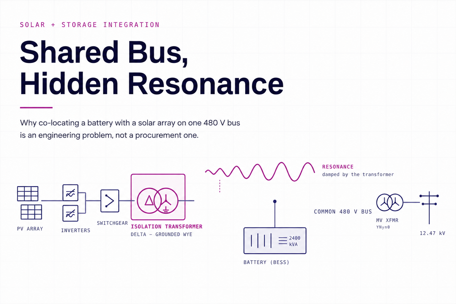
Shared Bus, Hidden Resonance
Aug 20, 2026 | Blog
Co-locating a battery with a solar array on one 480 V bus creates an electrical problem that no single piece of equipment owns — and that neither manufacturer will solve for you. Here is what actually has to be calculated before the transformer is ordered.
A solar array and a battery sharing a common 480 V collection bus is now the default architecture for co-located generation. It is efficient, it saves a transformer, and it works — until the two sets of power electronics start talking to each other through the bus impedance.
The failure mode does not announce itself. There is no bang, no trip on day one. What happens instead is a slow accumulation of symptoms that get attributed to everything else: nuisance inverter faults during light-load mornings, capacitor heating, harmonic alarms that the SCADA system logs and nobody reads, a protection relay that operates for no fault anyone can find. Sites run for months in this condition. Some run for years, quietly losing production and equipment life.
The cause is resonance between the output filters of two independent inverter systems that were never designed to share a bus. And the fix — an isolation transformer or a line reactor — is cheap relative to the consequences, provided it is specified correctly. That last condition is where most of the difficulty lives.
1. Why a shared bus goes unstable
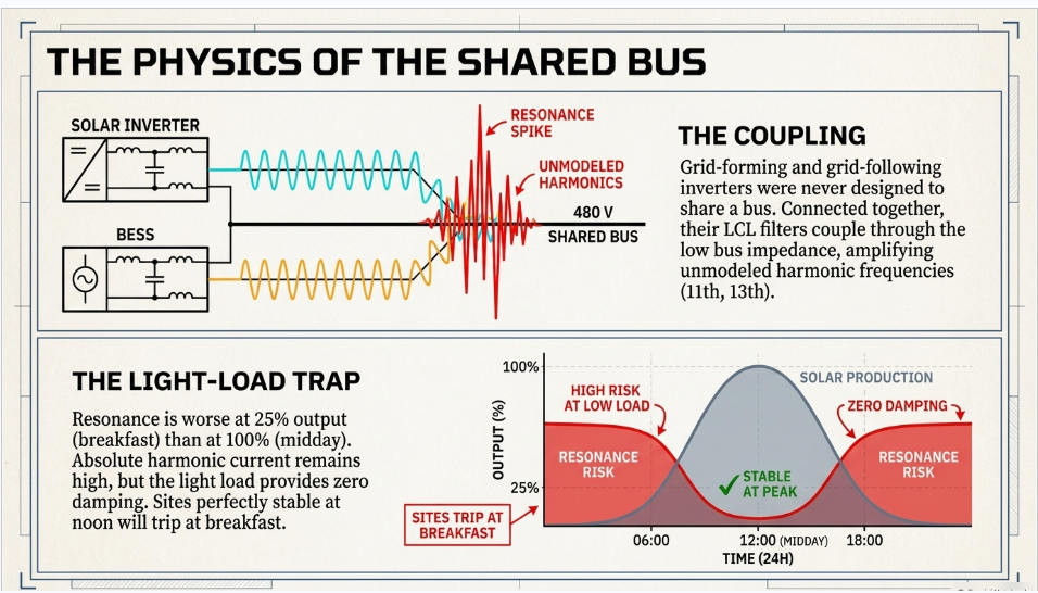
Every grid-forming or grid-following inverter has an output filter, almost always an LCL arrangement, whose job is to keep switching-frequency ripple out of the network. That filter is a resonant circuit. On its own, connected to a stiff grid, its resonant peak sits at a frequency the inverter’s own control loop is designed to damp, and nothing interesting happens.
Put a second inverter system on the same bus and the picture changes. The two filters are now coupled through the bus impedance, which is small. The combined network has resonant frequencies that neither manufacturer modelled, because neither manufacturer knew what else would be connected. If one of those frequencies happens to land near a harmonic order that either system produces — the 11th, the 13th, somewhere in the low hundreds of hertz to low kilohertz — the network amplifies it rather than damping it.
Amplification of a few per cent of harmonic current into something much larger is what produces the heating, the alarms and the spurious relay operations. The magnitude depends on how sharp the resonant peak is and how much damping the network provides, which is why two apparently identical sites can behave completely differently.
The part that catches people out
Resonance is worst at light load, not full load. Absolute harmonic current from switching ripple is roughly independent of real power output, so a site at 25 % output is injecting nearly the same absolute harmonic current into a network with far less damping from load. Sites that are perfectly stable at midday can misbehave at breakfast.
2. What the battery manufacturer requires
Tesla addresses this directly in the Megapack 2 XL Design and Installation Manual at §2.9.1, and the requirement is unusually concrete. Excessive resonance is expected — their word — when a Megapack shares a common 480 V AC bus with power electronics meeting both of two conditions:
- The total apparent power rating of the power electronics exceeds 20 % of the Megapack’s apparent power rating.
- The equivalent switching frequency at the AC bus is less than 35 kHz.
Both conditions are met on essentially every co-located solar-plus-storage site built today. A 2-hour Megapack 2 XL has a 2,400 kVA inverter rating, so the 20 % threshold is 480 kVA — less than three utility-scale string inverters. And no utility-scale inverter on the market switches anywhere near 35 kHz; silicon-carbide designs have raised switching frequencies considerably but remain an order of magnitude below that ceiling.
Where both conditions are met, three remedies are permitted: relocate the equipment, install a line reactor of at least 0.022 mH per phase, or install an isolation transformer with impedance between 3 % and 7 %. In both cases the mitigation must carry the continuous current of the connected equipment and must sit in series between the Megapack and the common AC bus.
A location detail worth reading twice
The manual places the mitigation between the battery and the bus. Many designers place it between the solar switchgear and the bus instead, which is often the better engineering choice and interrupts the same resonant loop. It is nonetheless a documented deviation, and it costs nothing to obtain written concurrence from the manufacturer’s applications engineering before the purchase order is placed. Warranty positions have been lost over less.
3. Reactor or transformer
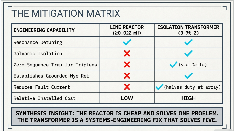
The reactor is dramatically cheaper. A 0.022 mH three-phase reactor is a fraction of the cost, size and lead time of a 2,500 kVA dry-type transformer, and it satisfies the manufacturer’s stated requirement. On a project where budget is under pressure, it is the obvious answer.
It is also, frequently, the wrong one — not because it fails to solve the resonance problem, but because it solves only the resonance problem. Co-located sites usually have two or three other issues in the same part of the single-line, and the transformer disposes of all of them at once.
| Capability | Line reactor | Isolation transformer |
|---|---|---|
| Detunes the shared-bus resonance | Yes | Yes |
| Galvanic isolation between the two systems | No | Yes |
| Zero-sequence trap for triplen harmonics | No | Yes, via the delta |
| Establishes a dedicated grounded-wye reference | No | Yes |
| Reduces available fault current on the array side | Not where it sits | Typically by about half |
| Relative installed cost | Low | High |
One row deserves expansion. A reactor at the manufacturer’s minimum of 0.022 mH presents 8.3 mΩ at 60 Hz, which on a 2,500 kVA, 480 V base is roughly 9 % impedance — larger than a typical transformer’s 5.75 %. The reactor is not a small impedance. But it sits in the battery branch, so it does nothing for fault duty or incident energy at the solar switchgear, which is where people are working.
4. Three ways the specification goes wrong
Assume the transformer is the chosen route. Three specification errors recur often enough to be worth naming, and all three survive vendor review because the vendor builds what the specification says.
4.1 Nobody says which winding faces the array
A specification that reads "Primary 480 V delta, secondary 480 V wye" is ambiguous in a photovoltaic application, because real power flows from the array toward the utility while transformers are conventionally described from the utility side. A vendor can reasonably build that unit with the delta facing either direction.
The direction is not a detail. Standard transformerless string inverters require a grounded wye source facing the inverters — the system’s neutral must be grounded so that line-to-ground voltage is defined and bounded. Certain variants require the exact opposite, a floating ungrounded source. Get the orientation backwards and either the inverters lose the reference they need, or a variant that must float finds itself grounded.
Write it physically, not by label
State on the purchase order and confirm on the approval drawings: wye winding facing the solar switchgear, neutral brought out and grounded at a single point; delta winding facing the medium-voltage transformer.
Do not rely on the words primary and secondary to carry that meaning, because they do not.
4.2 Sizing on real power divided by power factor
The familiar calculation is S = P ÷ PF. For a 2 MW site at 0.90 power factor that gives 2,222 kVA, rounded up to a 2,500 kVA standard rating. The arithmetic is correct and the answer often happens to be right, but the reasoning does not apply to an inverter block.
String inverters are apparent-power limited. A 200 kVA unit with adjustable power factor delivers 200 kVA total; at 0.90 PF that is 180 kW of real power, not 200 kW plus reactive on top. Ten of them total 2,000 kVA and deliver 1,800 kW at 0.90 PF. There is no operating point at which 2,222 kVA flows.
The correct basis is aggregate inverter apparent power. It matters because the same faulty reasoning applied to a 1.5 MW block gives 1,667 kVA and invites a 1,500 kVA transformer that is exactly at its rating with zero margin — for a continuous-duty source, on cold clear days, with no allowance for future inverter addition.
4.3 Buying more K-factor than physics requires
K-factor is the standard way of rating a transformer for harmonic heating, and it is routinely over-specified. The definition, per UL 1561, sums over all orders including the fundamental, with harmonic current expressed in per unit of rated RMS load current:
K = Σ ( I h, pu )² × h²
The order-squared weighting looks alarming and drives people toward K-13 or K-20. But the fundamental term dominates the sum, so a fixed quantity of distortion produces far less variation in K than the weighting suggests. Take a modern silicon-carbide inverter with published total current distortion under 3 % at rated load, and place all of that distortion at a single harmonic — the least favourable case that can physically exist:
| Harmonic order | Required K | Harmonic order | Required K |
|---|---|---|---|
| 5th | 1.02 | 25th | 1.56 |
| 13th | 1.15 | 47th | 2.99 |
| 50th — worst case | 3.25 |
A conclusion you can reach without measuring anything
Even in the physically unrealisable worst case, the required K-factor is 3.25. Any realistic distribution across the low orders gives between 1.0 and 1.6. K-4 is adequate under every spectral distribution consistent with a published sub-3 % distortion figure, and escalating beyond it buys physical size and cost with no technical basis. This is a bounding argument, and measurement cannot overturn it.
5. The grounding consequence nobody budgets for
Install a transformer with a grounded wye winding facing the array and you have created a separately derived system under NEC Article 250.30. This is not optional and it is not free. It requires a system bonding jumper at one point only, a grounding electrode conductor sized to Table 250.66 and run to a grounding electrode at the transformer or first disconnecting means, and a supply-side bonding jumper.
None of that exists before the transformer is installed, because the array’s ground reference previously came from the medium-voltage transformer’s secondary. Adding the isolation transformer moves the reference, and every downstream assumption about ground-fault detection moves with it.
There is a second-order trap here that catches experienced installers. Standard string inverters commonly ship with the neutral terminal bonded to the ground terminal at the factory. Establish a new single-point bond at the transformer and every inverter’s internal bond becomes an additional reference tied in through the equipment grounding conductor. Manufacturers generally publish a procedure for lifting that internal bond; whether it should be lifted is a per-site determination under NEC 250.30 and 250.6, and it should be settled with the manufacturer in writing rather than decided on a ladder.
6. The question the inverter manufacturer cannot answer
A recurring exchange on these projects goes roughly as follows. The designer asks the inverter manufacturer whether it is acceptable for the neutral to be established by a separate grounding transformer rather than bonded at the inverter. The manufacturer replies that a grounded wye transformer is required. Both parties believe the question has been answered. It has not.
What the inverter requires is a grounded wye source — a defined, bounded ground reference. A zig-zag or grounded wye-delta grounding transformer provides exactly that. So the answer is yes, in principle, subject to one condition that the inverter manufacturer is in no position to evaluate: the resulting system must be effectively grounded at the inverter terminals.
Per IEEE C62.92.1 that means X0/X1 not greater than 3 and R0/X1 not greater than 1, giving a coefficient of grounding of 80 % or less of nominal line-to-line voltage — equivalently, line-to-ground voltage on the unfaulted phases held within roughly 1.38 per unit of nominal line-to-neutral during a ground fault. A grounding transformer of inadequate rating or excessive zero-sequence impedance will not meet it, and the inverter is then exposed to a temporary overvoltage it was never rated to withstand.
Whether any particular arrangement qualifies is a symmetrical-component calculation on your system. The manufacturer cannot perform it, because the answer depends on impedances they have never seen.
A related point about delta windings
A grounded-wye winding presents low zero-sequence impedance only when it is backed by a delta winding or a delta tertiary. A wye-to-grounded-wye unit without one presents high zero-sequence impedance and will generally fail the X0/X1 criterion.
This is worth checking on the existing medium-voltage transformer: a YNyn0 vector group with no tertiary means the site has no zero-sequence trap anywhere between the inverters and the utility, and triplen harmonics pass straight through. The nameplate will tell you in about ten seconds.
7. What calculation settles, and what needs a meter
Projects stall when this boundary is unclear, usually because someone has been told that nothing can proceed without a power-quality survey. That is not true, and the distinction is worth being precise about, because the equipment decision does not depend on measurement at all.
| Question | Source of the answer |
|---|---|
| Transformer kVA and full-load current | Calculation |
| Vector group and physical winding orientation | Calculation |
| Adequacy of the K-rating | Calculation — bounding argument |
| Impedance compliance with the manufacturer’s band | Calculation |
| Voltage regulation and tap requirement | Calculation |
| Effective grounding — X0/X1, R0/X1, COG | Calculation |
| NEC 250.30 separately derived system design | Calculation |
| Available fault current and protection basis | Calculation |
| Location of network resonant frequencies | Modelling — reliable, with a sensitivity range |
| Magnitude of harmonic excitation | Measurement |
| Demonstrated IEEE 519 compliance at the PCC | Measurement — 7-day continuous |
| Per-order spectrum at 100 / 75 / 50 / 25 % output | Measurement |
Everything governing the purchase order is in the top block. A desktop study settles the equipment decision completely. Measurement is required for the utility submission and for quantifying resonance excitation — genuinely necessary work, but not on the critical path to ordering steel.
If you are recording the data yourself
Get the measurement specification written before anyone deploys an instrument. IEEE 519 compliance is assessed statistically — twelve-cycle windows aggregated to three-second values, two hundred of those aggregated to ten-minute values, evaluated at the 95th and 99th percentile over a continuous seven-day period, orders 2 through 50, with instrumentation to IEC 61000-4-7 and IEC 61000-4-30 Class A.
A seven-day recording made with the wrong instrument class or the wrong aggregation cannot be repaired in analysis. It has to be done again.
8. Before the purchase order goes out
- Confirm per-site AC capacity against the inverter schedule, not the project name — drawing revisions lag capacity changes more often than not
- State winding orientation physically: which winding faces the array, and where the single grounding point is
- Confirm the inverter variant, standard or floating, because they impose opposite grounding requirements
- Read the existing medium-voltage transformer nameplate for the vector group and check whether a zero-sequence trap exists anywhere
- Verify impedance against the battery manufacturer’s band, including the ±7.5 % manufacturing tolerance permitted by IEEE C57.12.01
- Size the K-rating on a bounding calculation and resist escalation without a supporting number
- Obtain written concurrence from the battery manufacturer if the mitigation sits anywhere other than where the manual puts it
- Budget the separately derived system work — electrode, conductor, bonding, and revised ground-fault detection
- Settle the inverter internal neutral-to-ground bond in writing with the manufacturer
- Check whether the specified efficiency standard actually applies; a 480–480 V unit may qualify as special-purpose, which affects cost, size and lead time
9. Case studies
Note on these cases
The following are anonymised engineering scenarios drawn from co-located solar-plus-storage work. Client names, locations and identifying details have been removed, and figures have been rounded or adjusted where necessary to prevent identification. They are presented to illustrate the engineering, not as a client reference list.
| Sector | Scale | Topology | Issue class |
|---|---|---|---|
| Rural electric cooperative | 4 sites, 1.5–2 MW each | PV + BESS, common 480 V bus | Specification error, pre-order |
Case 1 — The transformer that would have been built backwards
Situation.
A cooperative was developing four co-located solar-plus-storage sites and had reached the point of quoting isolation transformers to satisfy the battery manufacturer’s resonance requirement. A specification had been drafted internally and circulated to vendors: 1,500 kVA, dry type, 480 V delta primary, 480 V wye secondary, K-4, electrostatic shield, 5.75 % impedance, NEMA 3R. The intent was to install between the solar array switchgear and the existing medium-voltage transformer.
The specification was, on its face, competent. Impedance sat within the manufacturer’s band. The K-rating was reasonable. The shield was correctly called for. Nothing in it would have caused a vendor to raise a query.
What the review found.
Three issues, in ascending order of consequence.
The capacity was wrong for three of the four sites. At 480 V, 1,500 kVA is 1,804 A. A 2 MW inverter block draws 2,406 A continuously. The figure appeared to have been derived from the smallest site, where it was an exact match with zero margin, and then applied uniformly. Two of the four sites would have received a transformer overloaded by a third from the day of energisation.
The medium-voltage transformer nameplate — obtained as a photograph during the review — showed vector group YNyn0 with no delta tertiary. The site therefore had no zero-sequence trap anywhere between the inverters and the utility. This confirmed the designer’s instinct that a delta was required, but for a reason nobody had articulated, and it made the winding arrangement more consequential than anyone had realised.
Most seriously, the specification never stated which winding faced the array. Under the intended installation the inverters would draw their grounded-wye reference from the new transformer rather than from the medium-voltage unit. A vendor building delta-toward-the-array — a perfectly reasonable reading of "primary" — would have delivered four transformers that left the inverter side ungrounded. The inverters in question required a grounded wye source. The error would not have surfaced until commissioning.
Resolution.
The specification was reissued with the winding arrangement stated in physical terms rather than by primary and secondary labels, capacity revised to 2,500 kVA at the larger sites, and a note added on the separately derived system obligations the new grounded wye would create. A rating conflict between the project’s stated capacity and the inverter schedule on the issued single-line was raised as a hold point before any order was placed.
Outcome
Four transformers correctly configured at first order. The winding-orientation error alone would have been discovered at commissioning across four sites, with replacement lead times measured in months against a construction programme with no float.
| Sector | Scale | Topology | Issue class |
|---|---|---|---|
| Independent power producer | Single site, ~2.5 MW | PV + BESS, common 480 V bus | Post-energisation instability |
Case 2 — The reactor that solved the wrong problem
Situation.
An operating site had been built with a line reactor as the resonance mitigation, selected on cost during value engineering and installed in the battery branch exactly as the manufacturer’s manual specified. The reactor was correctly sized and correctly located, and the resonance it was installed to address did not occur.
The site nonetheless generated persistent problems. Ground-fault indications appeared on the inverters during grid disturbances with no fault found on investigation. Harmonic alarms logged at the revenue meter. The utility raised a query about neutral current on the medium-voltage feeder.
What the analysis found.
The reactor had been asked to do a job it does not do. It provided series impedance and detuned the resonant interaction, which was its purpose. It provided no galvanic isolation, no zero-sequence trap and no independent ground reference — and the site needed all three for reasons unconnected to resonance.
The medium-voltage transformer was a grounded-wye to grounded-wye unit without a tertiary. Triplen harmonics and zero-sequence unbalance passed directly between the 480 V collection system and the medium-voltage network in both directions. The inverters’ ground reference came through that same transformer, so every zero-sequence disturbance on the utility system arrived at the inverter terminals essentially unattenuated. The nuisance ground-fault indications correlated with utility-side events, which is why no fault was ever found on site.
The utility’s neutral current query had the same root. With no delta anywhere in the path, triplen currents from the collection system had nowhere to circulate and appeared on the medium-voltage neutral.
Resolution.
A delta to grounded-wye isolation transformer was added in the solar branch, sized to the inverter block. The delta provided the zero-sequence trap the system had never had, the grounded wye gave the array a reference under the owner’s control rather than the utility’s, and the added series impedance reduced fault duty at the solar switchgear as a secondary benefit. The reactor was left in place; it was doing no harm and removing it would have required revisiting the manufacturer’s design review.
Outcome
Nuisance ground-fault indications ceased. The utility’s neutral current query closed. The cost of retrofitting a transformer into an energised site — outage, revised drawings, re-submission to the utility — substantially exceeded what the transformer would have cost at the original order, which is the general lesson of the case.
| Sector | Scale | Topology | Issue class |
|---|---|---|---|
| EPC contractor | 2 MW reference design | PV + BESS, common 480 V bus | Design document review |
Case 3 — A specification that described the wrong machine
Situation.
A three-page engineering design report and technical specification was circulated for review before being issued to transformer vendors. It was well presented, carried a calculation section, cited standards, and read as competent technical work. It was titled as a specification for an isolation and harmonic mitigating transformer.
What the review found.
The threshold problem was that the document specified a 12.47 kV delta to 480Y/277 V liquid-filled pad-mount transformer with a 65 °C temperature rise and copper windings. That is a medium-voltage distribution transformer. The equipment actually under procurement was a 480 V to 480 V dry-type unit — a different class of machine on every defining parameter. A 65 °C rise is a liquid-filled parameter; dry-type units are specified at 80, 115 or 150 °C. Issued as written, vendors would have quoted a replacement for the transformer already installed on site.
More consequentially, the specified transformer would not have satisfied the battery manufacturer’s requirement under any reading. The medium-voltage transformer sits upstream of the common bus, outside the resonant loop between the two inverter systems. Placing a delta there does nothing to the impedance between them.
The calculation section contained errors that would not have survived utility review. A claimed K-factor range of 3.2 to 3.8 did not follow from the document’s own assumptions — 5 % distortion across the 5th, 7th, 11th and 13th orders yields approximately 1.1, and reaching 3.2 within those orders would require roughly 11 % at the 13th harmonic alone. The K-factor formula was written with harmonic current referenced to the fundamental rather than to rated RMS current, and omitted the fundamental term. A short-circuit figure on the primary side was labelled as available fault current when it was through-fault current referred to the primary. And a passage attributing the K-rating to prevention of "core saturation and thermal runaway" contradicted the document’s own correct statement of the eddy-current mechanism two paragraphs earlier — core saturation is a volts-per-hertz phenomenon, unrelated to harmonic load current.
Several conclusions were nonetheless correct. The 2,500 kVA rating, the K-4 selection, the delta winding for triplen trapping and the electrostatic shield were all the right answers. The derivations simply did not establish them.
Resolution.
A severity-ranked review memorandum was issued identifying three critical findings, ten significant and four minor, with the correct value stated against each. The correct conclusions were carried forward into a reissued specification. The document was withdrawn before it reached vendors.
Outcome
The reissued specification produced comparable quotations for the correct equipment. The broader lesson concerned document provenance: the report had the characteristics of generated technical content — clean structure, confident tone, specific-looking figures that did not survive arithmetic checking. Any calculation entering a procurement or a utility submission should be independently verified regardless of how authoritative the source document appears.
10. Where this usually lands
The isolation transformer question looks like a procurement item and behaves like a systems-engineering problem. The transformer itself is straightforward; what makes these projects difficult is that the decision sits at the intersection of three parties’ scopes and belongs cleanly to none of them. The battery manufacturer specifies a mitigation without knowing the array. The inverter manufacturer specifies a grounding requirement without knowing the system impedances. The utility imposes conditions at the interconnection without visibility of either.
The work that closes it is unglamorous and mostly arithmetic: aggregate the inverter ratings honestly, read the nameplate, run the symmetrical components, write the winding arrangement down in words that cannot be misread. None of it requires waiting for a measurement campaign, and all of it is cheaper than discovering the answer at commissioning.
11. Frequently asked questions
Check the two conditions arithmetically rather than assuming. Total the apparent power of every inverter on the shared bus and compare it against 20 % of the battery’s apparent power rating. On a co-located site the solar block almost always exceeds it by several multiples. The switching-frequency condition is met by every utility-scale inverter currently sold. If both conditions are met, mitigation is a requirement rather than a recommendation, and skipping it puts the battery warranty at risk.
Electrically, yes — the resonance arises from interaction across the shared bus, and inserting series impedance with galvanic isolation anywhere in that loop detunes it. Solar-side placement also sizes the unit to the solar block rather than the battery’s inverter rating, gives the array a dedicated ground reference, and reduces fault duty where people work. It is nonetheless a departure from the written requirement, so obtain written concurrence from the battery manufacturer first. That correspondence costs nothing and protects the warranty position.
It gives a grounded wye, but check whether it has a delta tertiary. A YNyn0 vector group with no tertiary provides a high zero-sequence impedance and no path for circulating triplen harmonics, so the site has no zero-sequence trap between the inverters and the utility. It may also fail the effective-grounding criterion. The nameplate states the vector group; it is worth a photograph before any design work proceeds.
For standard transformerless string inverters: the grounded wye. The delta faces the medium-voltage transformer, where it also serves as the zero-sequence trap. Note that some inverter variants — those designed for floating DC arrays — require the exact opposite, an ungrounded source, and shipping the wrong configuration to those is a commissioning failure rather than a performance shortfall. Confirm the variant in writing before ordering.
Almost certainly K-4, and almost certainly not more. Run the bounding calculation: take the published total current distortion at rated load, place all of it at the highest harmonic order of interest, and compute K. For a modern inverter with sub-3 % distortion, even that unrealisable worst case lands at about 3.25. K-13 and K-20 are designed for large populations of single-phase non-linear loads — office buildings full of switch-mode supplies — not for utility-scale inverters with active filtering.
No. Most inverter manufacturers publish only aggregate total distortion, and most decline to release output filter values on the reasonable grounds that filter response cannot be assessed independently of the transformer impedance it works against. Neither refusal blocks the equipment decision. The K-rating is closable by bounding argument, and the resonance model can be built with a typical filter representation and reported as a sensitivity range. What you lose without the spectrum is precision in the excitation magnitude, not the ability to specify the transformer.
On a three-wire connection with no neutral conductor landed, no — and this is guaranteed by topology rather than merely asserted by the manufacturer, because zero-sequence current requires a return path and there is none. Two qualifications: the conclusion applies to balanced triplen sets, since unbalanced triplens contain positive- and negative-sequence components that flow freely in three wires; and it holds only while no neutral is landed, so it must be revisited if one is ever added for metering or auxiliary supply.
That is a different phenomenon and it is real. Transformerless inverters impress a common-mode voltage at switching frequency on the PV array, which drives capacitive leakage current through the array-to-ground capacitance and returns on the equipment grounding conductor. It is not zero-sequence current at fundamental frequency. It bears on conductor sizing and on residual-current monitoring thresholds, and it is worth quantifying rather than assuming. Note that an electrostatic shield in the isolation transformer addresses inter-winding coupling across the transformer, not this array-side loop.
In principle yes, subject to a calculation. The requirement is a defined and bounded ground reference, which a zig-zag or grounded wye-delta grounding transformer provides. The condition is that the resulting system is effectively grounded at the inverter terminals — X0/X1 ≤ 3 and R0/X1 ≤ 1 per IEEE C62.92.1. An undersized grounding transformer will not satisfy it. Note also that if the isolation transformer is built delta to grounded-wye with the wye facing the array, a separate grounding transformer becomes unnecessary at low voltage.
It depends on where your single bonding point ends up, and it should be settled in writing with the manufacturer rather than on site. Once a new separately derived system is bonded at the transformer, each inverter’s internal bond becomes an additional reference connected through the equipment grounding conductor. NEC 250.6 governs the objectionable-current concern. Most manufacturers publish an isolation procedure in the installation manual; the question is whether to use it, not whether it exists.
The complication on the photovoltaic side is that inverter fault contribution is current-limited — typically only 1.5 to 2 times rated output, and it does not decay like a machine contribution. Five 200 kW inverters contribute on the order of 1,500 A total. That is high enough to matter and low enough that fuse coordination becomes awkward, particularly where the same devices must also coordinate with utility-side protection and provide ground-fault detection on a newly created separately derived system. A coordination study answers it properly; the answer is site-specific and depends heavily on the utility’s requirements at the interconnection.
On the array side, usually yes and often substantially. Putting the transformer impedance in series with the medium-voltage transformer typically halves available fault current at the solar switchgear. Whether that translates into a lower incident-energy category depends on the clearing time as well as the current, which is why it needs a study rather than an assumption — reducing current while lengthening clearing time can move incident energy the wrong way.
Worth specifying. Adding a transformer in series introduces roughly 1.5 % additional voltage drop at full load at unity power factor, more at reduced power factor. Inverters have a finite AC voltage window within which they can export, and consuming part of that headroom for no reason is avoidable. Two 2.5 % taps above and below nominal on the winding facing the medium-voltage transformer costs very little at the time of order and cannot be added afterwards.
Confirm it with the manufacturer rather than assuming either way. A 480 V delta to 480 V wye unit is the classic drive-isolation configuration, and several manufacturers offer it as a special-purpose unit outside the scope of the distribution transformer standard. If it qualifies as exempt there may be a meaningful saving in cost, physical size and lead time. Specifying the efficiency standard alongside a K-rating, a low temperature rise and aluminium windings narrows the vendor pool considerably.
The engineering is a few weeks; the schedule is usually governed by data availability rather than analysis. What it needs: per-site inverter schedules and aggregate capacity, the inverter model and variant, battery configuration and any programmed kVA limit, transformer nameplates with as-set tap positions, the collection cable schedule with route lengths, utility short-circuit MVA and X/R at the interconnection, and the interconnection agreement. Where a value genuinely is not available, a typical value can be substituted — but it should be labelled as an assumption in the report, with a statement of how sensitive the result is to it.

About the Author:
Sandip "Sonny" R. Patel, P.E.
IEEE Senior Member · Founder & CEO, Keentel Engineering
In 1995, Sonny Patel earned his Electrical Engineering degree from the University of Illinois. But degrees don't build legacies — action does.
For three decades, he has worked the power industry from every side of the table: 16 years as a utility engineer at Exelon/Commonwealth Edison; generation leadership across hydroelectric, industrial steam turbine, and a 9 GW renewable fleet; NERC Regional Entity Senior Compliance Engineer and Audit Team Lead, auditing some of the nation's largest utilities; and testing and commissioning lead on equipment up to 765 kV — the very top of the North American grid.Utility. Generator. Regulator. Consultant. Few engineers have seen all four seats. Fewer still have sat in them.
His experience spans nuclear, hydro, conventional generation, renewables, oil and gas, mining — and today's data centers, where he is authoring a three-book series on data center design. He is a Licensed Professional Engineer in six states and a Licensed Electrical Contractor in Florida (Unlimited EC) — he doesn't just design the work; he's qualified to stand behind its execution.Today, as Founder and CEO of Keentel Engineering, Sonny leads a nationwide team of engineers delivering substation design, power system studies, NERC compliance, and commissioning — done right, coast to coast.Three decades. Every side of the table. One standard: accountable engineering.
Services

Let's Discuss Your Project
Let's book a call to discuss your electrical engineering project that we can help you with.
About the Author:
Sandip "Sonny" R. Patel, P.E.
IEEE Senior Member · Founder & CEO, Keentel Engineering
In 1995, Sonny Patel earned his Electrical Engineering degree from the University of Illinois. But degrees don't build legacies — action does.
For three decades, he has worked the power industry from every side of the table: 16 years as a utility engineer at Exelon/Commonwealth Edison; generation leadership across hydroelectric, industrial steam turbine, and a 9 GW renewable fleet; NERC Regional Entity Senior Compliance Engineer and Audit Team Lead, auditing some of the nation's largest utilities; and testing and commissioning lead on equipment up to 765 kV — the very top of the North American grid.
Utility. Generator. Regulator. Consultant. Few engineers have seen all four seats. Fewer still have sat in them.
His experience spans nuclear, hydro, conventional generation, renewables, oil and gas, mining — and today's data centers, where he is authoring a three-book series on data center design. He is a Licensed Professional Engineer in six states and a Licensed Electrical Contractor in Florida (Unlimited EC) — he doesn't just design the work; he's qualified to stand behind its execution.
Today, as Founder and CEO of Keentel Engineering, Sonny leads a nationwide team of engineers delivering substation design, power system studies, NERC compliance, and commissioning — done right, coast to coast.Three decades. Every side of the table. One standard: accountable engineering.
Leave a Comment
Thank you for contacting us.
We will get back to you as soon as possible.
We will get back to you as soon as possible.
Oops, there was an error sending your message.
Please try again later.
Please try again later.
Related Posts

By SANDIP R PATEL
•
October 6, 2026
Learn ERCOT generator testing for PFR, MOD-025 and MOD-026/027, including staged tests, capability verification, dynamic models and field testing.

By SANDIP R PATEL
•
October 3, 2026
Engineering guide to PRC-028 disturbance recording, PRC-029 ride-through and PRC-030 event detection for inverter-based resources.

By SANDIP R PATEL
•
October 3, 2026
A practical guide to SSO classification, SSR, PEDI, Wind-SSCI, EMT analysis, mitigation and protection based on CIGRE TB 909.

By SANDIP R PATEL
•
October 3, 2026
Learn how PV string I-V curve testing identifies hidden solar performance losses, including soiling, shading, mismatch, degradation, and wiring faults.

By SANDIP R PATEL
•
October 3, 2026
Learn how active harmonic filters work, how to size AHF systems, reduce VFD harmonics, calculate losses, and meet IEEE 519 TDD limits at the PCC.
By SANDIP R PATEL
•
October 3, 2026
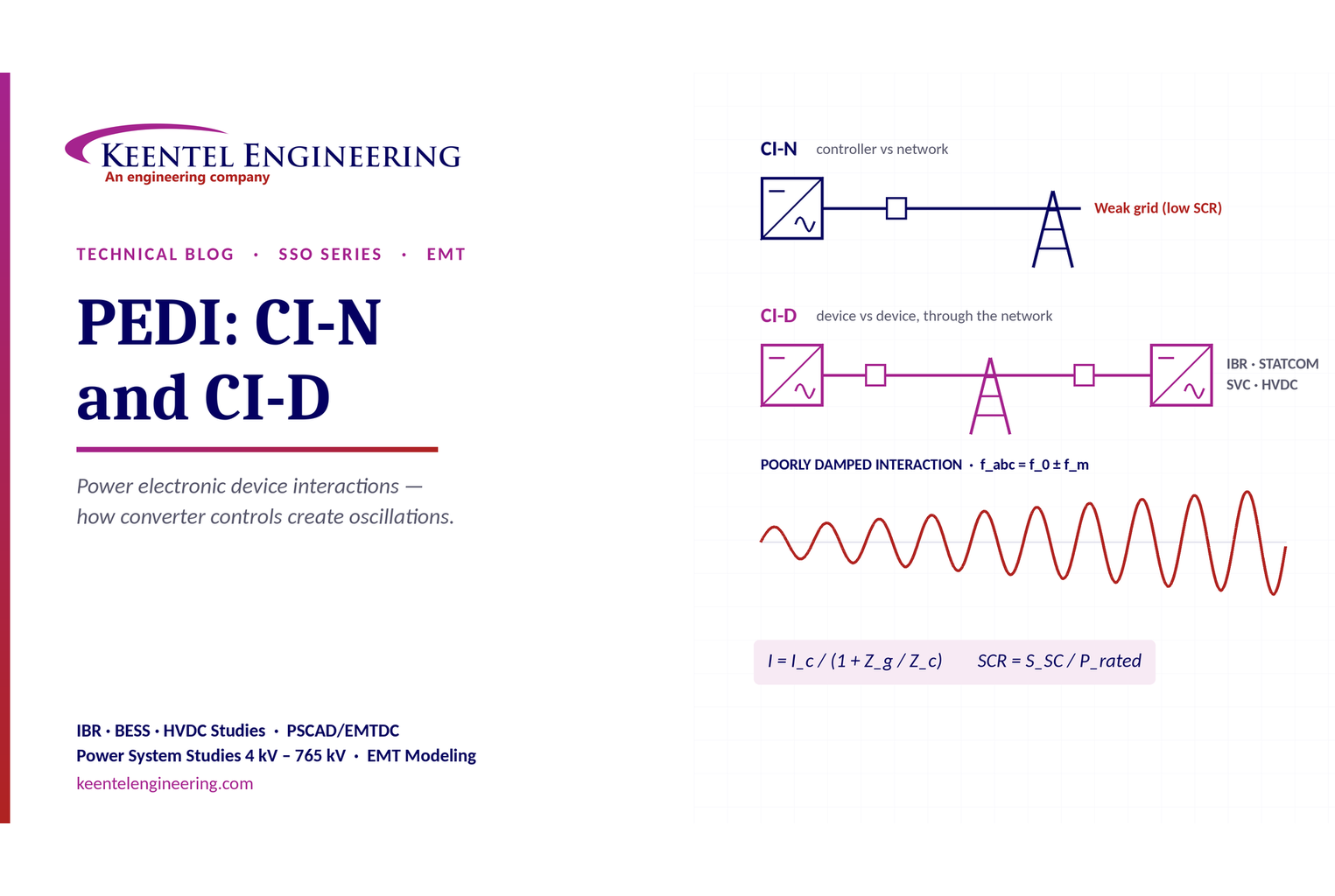
Learn power electronic device interactions (PEDI), including CI-N and CI-D, weak-grid stability, SCR, EMT studies, impedance analysis and mitigation for IBRs.
By SANDIP R PATEL
•
October 3, 2026
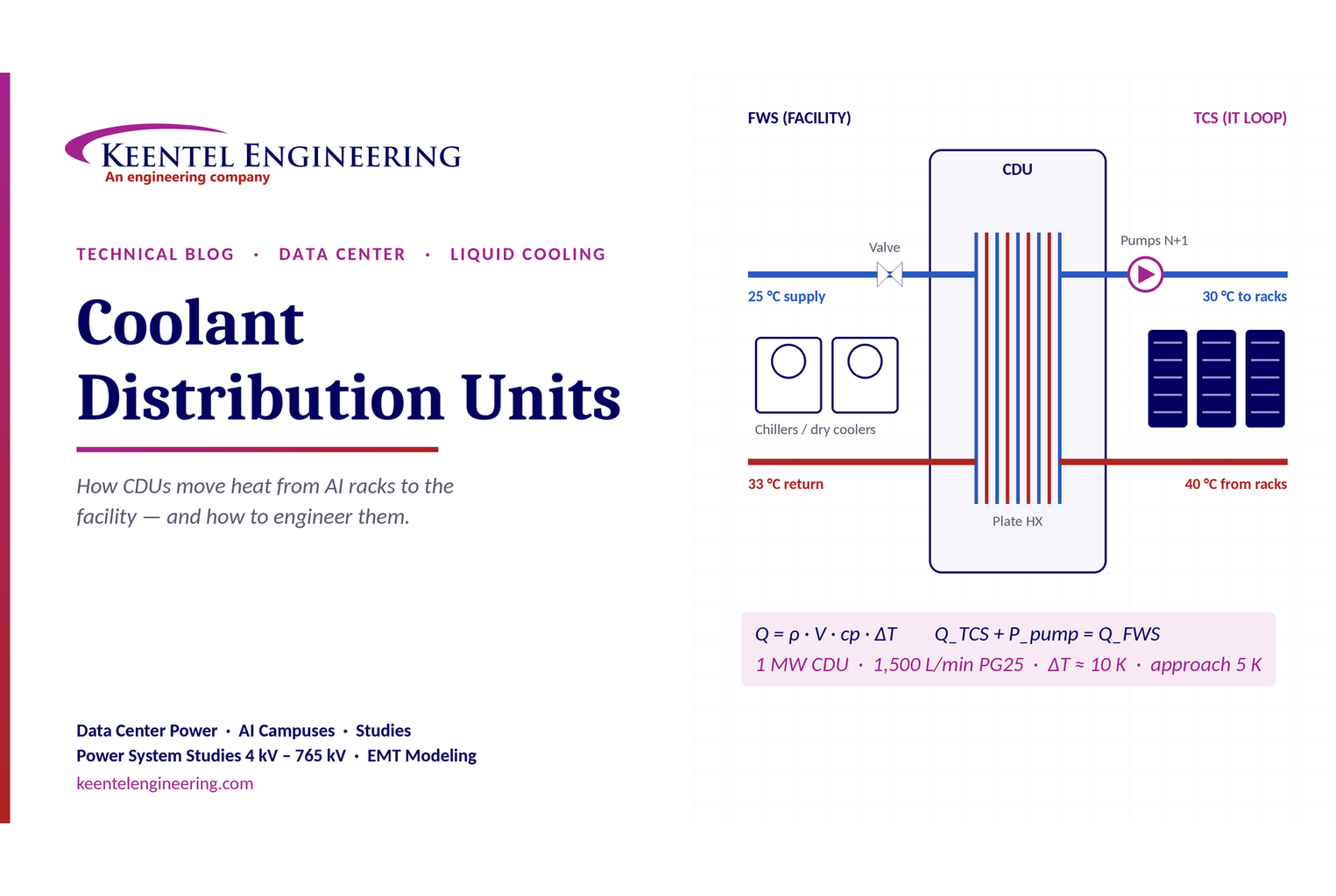
Learn how data center coolant distribution units (CDUs) work, including FWS and TCS loops, heat transfer, sizing, redundancy and liquid cooling for AI data centers.
By SANDIP R PATEL
•
October 3, 2026
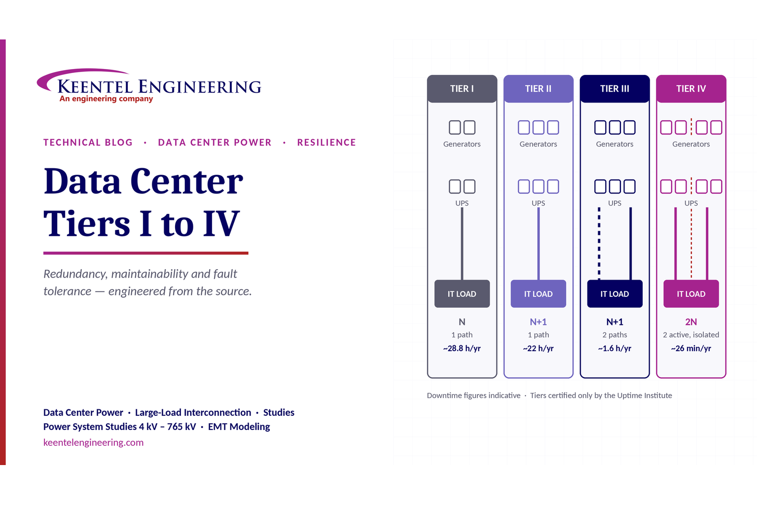
Compare Data Center Tiers I–IV, including redundancy, uptime, Tier III concurrent maintainability, Tier IV fault tolerance, UPS, generators and power design.

By SANDIP R PATEL
•
October 3, 2026
Learn how BESS supports grid stability through fast frequency response, voltage support, oscillation damping, black start, grid-forming controls and EMT studies.





