A Coordinated Electric System Interconnection Review—the utility’s deep-dive on technical and cost impacts of your project.
Challenge: Frequent false tripping using conventional electromechanical relays
Solution: SEL-487E integration with multi-terminal differential protection and dynamic inrush restraint
Result: 90% reduction in false trips, saving over $250,000 in downtime
The three operating regions you have to design to
| Device | Output vs voltage | Response | Best suited to | Main limitations |
|---|---|---|---|---|
| Mechanically switched capacitor or reactor | Proportional to voltage squared | Seconds; discrete steps; limited switching operations per day | Steady-state reactive supply, voltage profile, loss reduction | No dynamic capability; step voltage change on switching; capability collapses when most needed |
| Static var compensator | Capacitive branches proportional to voltage squared | A few cycles; continuously controllable | Continuous control where cost matters and deep voltage support is not the driver | Square-law capability loss; harmonic filters are part of the plant and interact with the network |
| STATCOM | Approximately proportional to voltage — constant current capability | One to two cycles closed loop; converter response faster still | Voltage stability margin, weak interconnections, fast disturbance recovery, flicker and unbalance compensation | Higher capital cost; converter losses; adds a converter and its control dynamics to the network |
| Synchronous condenser | Governed by machine capability and excitation | Excitation response in the hundreds of milliseconds; inherent inertial response instantaneous | System strength and inertia, short-circuit contribution, black start support | Rotating plant with maintenance and losses; slower controlled response than a converter |
| STATCOM with energy storage | Reactive as a STATCOM, plus real power within the storage rating | As STATCOM for reactive; real power limited by storage | Where a real power deficiency is part of the problem | Cost and complexity of the storage; different failure and maintenance profile |
| Stage | Keentel scope | Outcome |
|---|---|---|
| Screening | Series-compensation proximity, radial contingency review, UIF and short-circuit ratio screening, frequency scans | Early identification of which SSO types apply |
| Detailed studies | PSCAD/EMTDC EMT studies with vendor real-code models, impedance-based and frequency-scan analysis | Clear evidence of stability margins or risk |
| Model quality | EMT model review, benchmarking against positive-sequence models, model acceptance support | Models that system operators accept |
| Mitigation | Control retuning recommendations with vendors, SSDC and bypass logic requirements, protection and monitoring specifications | Practical, coordinated solutions |
| Interconnection support | SSR and SSO study reports for ISO and utility requirements, response to reviewer comments | Fewer delays in the interconnection process |
Resilience: designing CDUs to the facility Tier objective
Liquid cooling makes heat removal more critical, not less. Cold plates hold only seconds of thermal buffer. If TCS flow stops, processors throttle or shut down very quickly. Resilience design must therefore cover:
- Pump redundancy: N+1 pumps at minimum, with automatic changeover.
- CDU redundancy: N+1 CDUs on a common TCS header, or 2N CDUs serving A and B manifolds for fault-tolerant designs.
- Power to CDUs: dual-corded CDUs fed from A and B sources, with pumps and controls on UPS power so coolant keeps flowing through a utility failure and generator start. This is the liquid-cooling equivalent of continuous cooling.
- Facility water continuity: chilled water or condenser water must also continue, through thermal storage, UPS-backed pumps or a high enough FWS temperature that the TCS can coast on stored thermal mass for the transfer period.
- Concurrent maintainability: isolation valves so any CDU, pump, filter or manifold section can be serviced without stopping the others.
- Leak management: leak detection, drip trays, automatic isolation valves and procedures for fluid spills.
Electrical engineering considerations
CDUs and liquid-cooling plants are electrical loads with their own design requirements:
- Pump motors and VFDs. Large CDUs use variable-frequency drives on their pump motors. These introduce harmonic current that must be included in the facility's harmonic study and IEEE 519 evaluation.
- Critical mechanical load on UPS. Putting CDU pumps on UPS increases UPS and battery sizing. The mechanical UPS load must be included in redundancy and ride-through calculations.
- Feeder and protection design. Dual feeds, automatic transfer, selective coordination and arc-flash labelling apply to CDU power distribution just as they do to IT power.
- Generator transient response. CDU pumps restarting together after a transfer create motor inrush on the generators. Staged restarts and soft acceleration reduce the step load.
- Load dynamics. AI training loads can swing rapidly between high and low power. Cooling controls must track those swings without temperature overshoot, and electrical systems must handle both the IT and the cooling load changes.
Commissioning a liquid-cooled data hall
- Flush and clean the TCS piping and manifolds to the specified cleanliness, using high-purity flush water.
- Fill and vent with the specified coolant, verifying glycol concentration and chemistry.
- Pressure test for leaks at design and test pressures, including quick-disconnect fittings.
- Verify sensors and controls: flow meters, temperature sensors, pressure transmitters, leak detection and BMS points.
- Load test with heat load banks connected through the cold-plate interfaces or rack manifolds, across the operating range.
- Prove the heat balance on both loops at several load steps, and the approach temperature against the design.
- Test failure scenarios: pump failure, CDU failure, power transfer to generator, valve failure and loss of facility water, confirming temperatures stay within the IT vendor's limits.
How Keentel Engineering helps
Keentel Engineering supports data center owners, developers and EPCs with the electrical engineering that liquid-cooled facilities depend on, and coordinates with the mechanical engineer of record and cooling vendors on the integrated design.
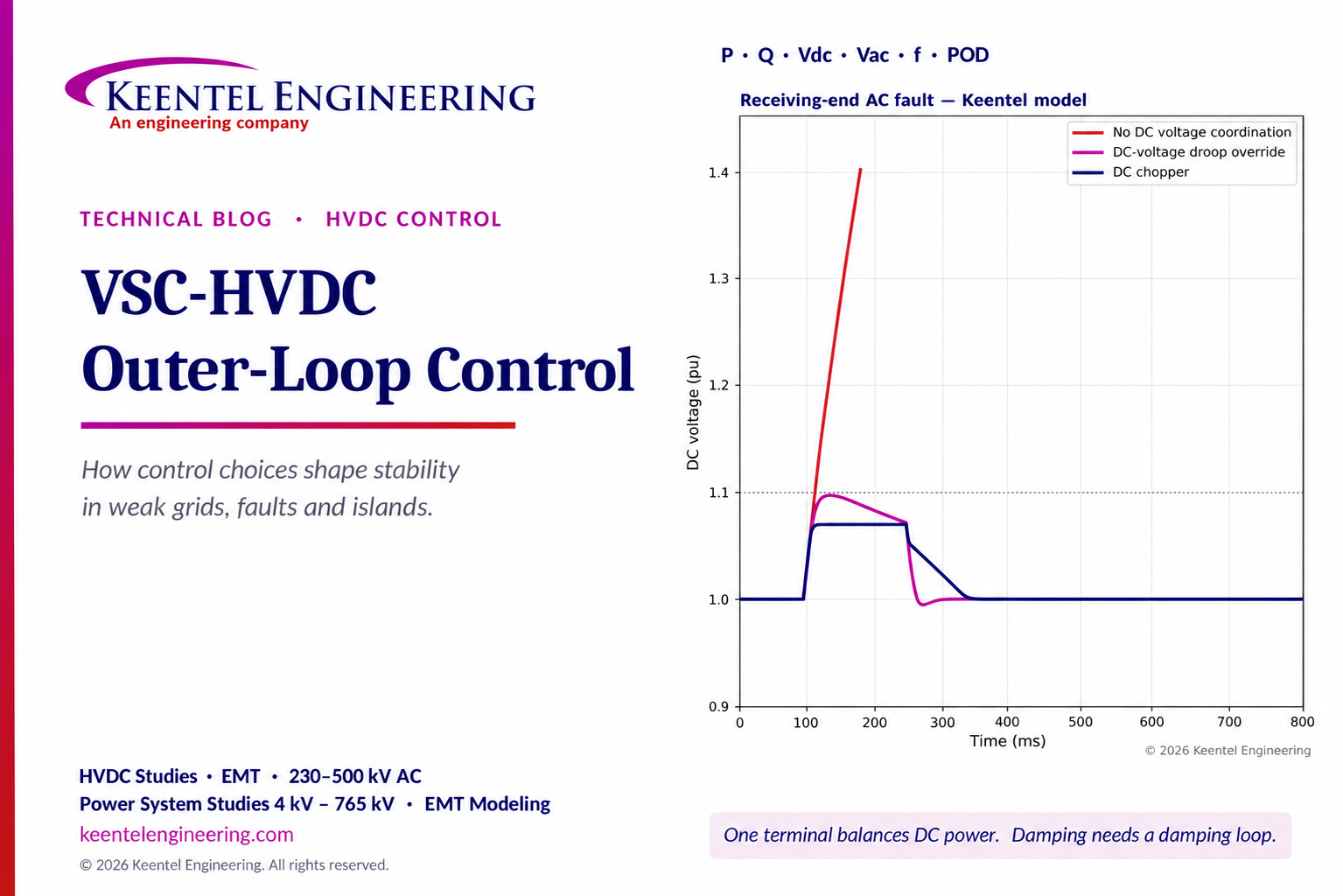
VSC-HVDC Outer-Loop Control: DC Voltage, P/Q Control & Grid Stability
October 24, 2026 | Blog
Part A — VSC-HVDC Outer-Loop Control at a Glance
A voltage-source converter (VSC) HVDC terminal is a power electronic machine whose behavior is defined almost entirely by its controls. Its inner current loop decides how fast and how precisely current is delivered. Its outer loops decide what that current is for: holding active power, holding reactive power, regulating DC voltage, regulating AC voltage or supporting frequency. The same hardware can stabilize a weak grid or destabilize it, damp an inter-area oscillation or ignore it, ride through a fault or trip on DC overvoltage — depending on which outer loop is selected and how it is coordinated with the other terminal.
The outer-loop menu
| Outer loop | What it controls | Typical use |
|---|---|---|
| Active power (P) | Power transferred over the link | Scheduled transfer at one terminal |
| DC voltage (Vdc) | DC link voltage, and therefore power balance | At least one terminal of every link |
| Reactive power (Q) | Reactive exchange with the AC system | Strong AC systems with separate voltage control |
| AC voltage (Vac) | Voltage at the converter AC bus | Weak AC systems, voltage support |
| Frequency (f) and P-f droop | Active power modulated with AC frequency | Frequency support, island supply |
| Power oscillation damping (POD) | Supplementary modulation of the P reference | Damping interarea oscillations |
| Grid-forming (voltage and frequency) | AC voltage magnitude and frequency directly | Offshore wind, islanded systems, black start |
Each terminal uses one active-axis loop (P, Vdc or f) and one reactive-axis loop (Q or Vac) at any time, with supplementary controls layered on top.
What Keentel's simulations show
Keentel Engineering built four reduced-order models of a VSC-HVDC link at 60 Hz to test common claims about outer-loop selection.
| Scenario | Configuration compared | Key result |
|---|---|---|
| Weak grid (SCR 1.8), 0.8 pu transfer, remote fault | Fixed Q = 0 versus AC voltage control | Fixed Q holds the bus at only 0.85 pu before and after the fault and loses the voltage during it; AC voltage control holds 1.00 pu using 0.19 pu reactive power and supports about 0.82–0.85 pu during the fault |
| Inter-area oscillation, about 0.39 Hz | Vdc control plus constant P versus Vdc control plus a POD loop | Without POD the mode damps at only about 1.9%; with POD it is effectively eliminated within 10 s. DC voltage control alone does not damp AC inter-area modes |
| Both terminals on P control, 1% power mismatch | — | DC voltage does not oscillate: it drifts monotonically, reaching 1.15 pu in about 2.6 s, where protection would block the link |
| Fault at receiving-end AC bus, 0.2 pu for 150 ms | No coordination versus rectifier DC-voltage droop versus DC chopper | Without coordination DC voltage exceeds 1.1 pu within about 17 ms and reaches 1.4 pu; droop limits it to 1.10 pu; a DC chopper limits it to 1.07 pu |
| 500 MW low-inertia island, loss of 100 MW | HVDC at fixed P versus 2% frequency droop | Fixed P: nadir 56.6 Hz; droop: nadir 59.5 Hz, with HVDC picking up 99 MW from the main grid |
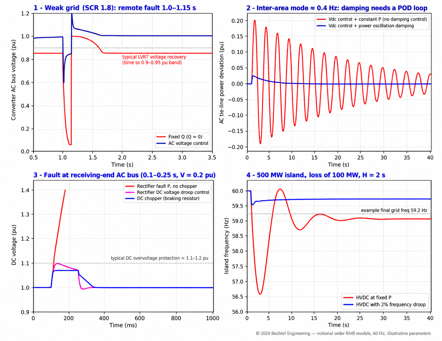
Figure 1. Keentel's reduced-order simulations of four VSC-HVDC outer-loop scenarios on a 60 Hz system.
Four lessons
- In weak grids, regulate AC voltage — carefully. Fixed reactive power cannot hold voltage at low short-circuit ratio. AC voltage control can, but it must be tuned in EMT studies so that it does not interact with the PLL and network.
- Damping comes from a damping controller, not from DC voltage control. One terminal must control DC voltage to keep power balanced; inter-area damping requires a supplementary POD loop that modulates active power.
- AC faults are DC voltage events. When the receiving end cannot export power, energy accumulates in the DC system within milliseconds. DC choppers, DC-voltage droop and coordinated control are essential.
- Frequency support comes from the other AC system, not the DC capacitors. DC-side stored energy is about 1% of a small island's rotating kinetic energy in Keentel's example. The benefit of frequency droop is power drawn from the main grid through the link.
Engineering review of common explanations
| Common statement | Keentel's correction |
|---|---|
| "Gas collects in the upper chamber and the float rises to operate the alarm." | Gas displaces oil from the top of the relay housing, so the oil level falls and the upper float drops, closing the alarm contact. Floats rise only when the relay is full of oil. |
| "In a severe fault, a large amount of gas makes the float rise further and operate the trip contact." | The trip element is a separate lower float with a flap (baffle) that is deflected by the oil surge toward the conservator. It also operates if oil is lost and the lower float drops. It does not depend on gas volume in the relay. |
| "Gas is automatically released through the gas vent to the conservator." | Gas is trapped in the relay housing for inspection and sampling through a test cock or gas sampling device. Only after the housing is full of gas does further gas pass up the pipe to the conservator. Analyzing the trapped gas is a key diagnostic step. |
| "Oil flows smoothly through the relay under normal conditions." | Under normal conditions oil moves only slowly as it expands and contracts with temperature. The relay must not operate on these flows or on oil movement from cooling pumps, through-faults or energization. |
| "The Buchholz relay is a fast fault-detection device." | It is sensitive but relatively slow: typically 50 to 300 ms or more, depending on fault energy. It supplements, not replaces, differential protection. |
| "Widely used in power transformers." | Widely used on conservator-type transformers worldwide and increasingly in the US on large units. Many US transformers use sealed tanks or nitrogen blankets without a conservator and therefore use sudden pressure relays instead. |
Part B — Outer-Loop Control of VSC-HVDC: An Engineering Guide for US Transmission, Offshore Wind and Interregional Links
1. VSC-HVDC in the US grid
VSC-HVDC has moved from niche to mainstream in North America. Urban cable links bring power into dense load centers where overhead lines are impossible; interregional links carry hydro and renewable energy hundreds of miles; offshore wind farms on the Atlantic coast are planned with HVDC export systems; and back-to-back converters connect asynchronous systems. Modern VSC links use modular multilevel converters (MMCs) with DC voltages commonly at ±320 kV, ±400 kV and ±525 kV, connecting to AC systems at 230 kV, 345 kV and 500 kV.
Compared with line-commutated converter (LCC) HVDC, VSC-HVDC:
- controls active and reactive power independently;
- does not need a strong AC system for commutation and can connect to very weak systems or create its own AC voltage;
- can black-start a network;
- reverses power without reversing DC voltage, making it well suited to cables and multi-terminal grids;
- has limited overcurrent capability, typically about 1.1 to 1.2 pu, because its semiconductors cannot tolerate sustained overload.
These characteristics make control design — and particularly outer-loop selection — central to system performance.
2. The VSC control hierarchy
2.1 Layers
| Layer | Function | Typical bandwidth or time scale |
|---|---|---|
| Converter valve and submodule control | Switching, capacitor voltage balancing within MMC arms | Microseconds |
| Inner current control | Regulates d-axis and q-axis currents; current limiting | About 1 to 5 ms response |
| Synchronization (PLL) or grid-forming angle | Aligns the control frame with the AC voltage, or creates it | About 10 to 50 ms (PLL); slower power-synchronization loops |
| Outer loops | P, Q, Vdc, Vac, f; produce current references | About 50 to 500 ms |
| Supplementary controls | POD, frequency droop, runback, emergency power control | 0.1 to several seconds |
| Station and system controls | Dispatch, mode selection, coordination between terminals | Seconds to minutes |
2.2 Inner current loop
In the synchronous reference frame aligned with the AC voltage, active power and reactive power are controlled by the d-axis and q-axis currents:

(using peak-value dq quantities; in per unit with power-invariant scaling, P = vd id and Q = −vd iq). The current limit constrains the combined current:
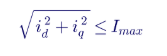
How the limit is shared between active and reactive current — active priority or reactive priority — is one of the most consequential settings in the converter, especially during faults.
2.3 Outer loops produce current references
| Outer loop | Typical control law |
|---|---|
| P control | id from PI on (P* − P) or directly P*/vd |
| Vdc control | id from PI on (Vdc* − Vdc) |
| Q control | iq from PI on (Q − Q*) or −Q*/vd |
| Vac control | iq from PI on (Vac* − Vac), often with droop on reactive current |
| f droop | P* = P0 − (Δf/f0)/R × Prated, feeding the P loop |
| POD | P* = P0 + KPOD·G(s)·Δω, feeding the P loop |
2.4 Modular multilevel converter fundamentals
Modern VSC-HVDC uses modular multilevel converters. Each phase has an upper and lower arm, and each arm contains hundreds of series-connected submodules — half-bridge or full-bridge cells, each with its own capacitor. The converter builds a near-sinusoidal AC voltage by inserting or bypassing submodules, so switching losses and harmonics are low and AC filters are usually unnecessary.
| Characteristic | Typical value or practice |
|---|---|
| DC voltage (symmetric monopole or bipole) | ±320 kV, ±400 kV, ±525 kV |
| AC connection | Converter transformer to 230 kV, 345 kV or 500 kV onshore systems; offshore converter AC voltage selected by the designer, commonly in the 230 kV class in US projects |
| Converter ratings per station | Several hundred MW to about 2,000 MW |
| Station losses | About 1% of rated power per station at full load |
| Stored energy | About 30 to 40 kJ per MVA in submodule capacitors |
| Overcurrent capability | About 1.1 to 1.2 pu continuous capability margin; short-term limits set by semiconductors |
| Submodule type | Half-bridge for most cable schemes; full-bridge or hybrid where DC fault blocking is needed |
The arm energy is itself controlled: MMC internal controls balance capacitor voltages within and between arms and suppress circulating currents. These internal loops are fast and usually invisible to system studies, but they constrain how much energy can be exchanged with the DC system during disturbances.
3. DC voltage and power balance
3.1 The DC energy balance
The DC system stores energy in converter capacitors (in MMCs, distributed in submodules) and cables. Energy balance gives:
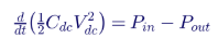
Defining an equivalent DC inertia constant per terminal:
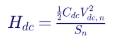
the per-unit dynamics become:

MMC converters typically store on the order of 30 to 40 kJ per MVA, so Hdc is about 0.03 to 0.04 s per terminal.
3.2 Worked example: how fast DC voltage rises
With Hdc = 0.04 s and a 1.0 pu power imbalance, the time for DC voltage to rise from 1.0 to 1.1 pu is:

The DC voltage does not oscillate; it drifts. In point-to-point links, one terminal (usually the inverter, but sometimes the rectifier) controls DC voltage and the other controls active power. In multi-terminal systems, several terminals share DC voltage control through DC-voltage droop:

so that power imbalances are shared among terminals in proportion to their droop gains.
3.4 Control modes for a point-to-point link
| Terminal 1 | Terminal 2 | Behavior |
|---|---|---|
| P | Vdc | Standard: scheduled power at terminal 1, terminal 2 balances |
| Vdc | P | Equally valid; choice depends on which AC system is stronger and fault response strategy |
| P | P | Not viable: DC voltage drifts until protection blocks |
| Vdc | Vdc | Not viable without droop: controllers fight |
| Vdc droop | Vdc droop | Viable, shares balancing; common in multi-terminal schemes |
3.5 DC faults and their effect on control strategy
A DC-side fault — a cable insulation failure or, for overhead DC lines, a lightning-induced pole-to-ground flashover — collapses DC voltage. Half-bridge MMCs cannot block DC fault current, because their freewheeling diodes form an uncontrolled rectifier from the AC side; the fault must be cleared by opening AC breakers, which takes several cycles and interrupts transfer. Full-bridge or hybrid submodules can drive DC current to zero by inserting negative voltage, and HVDC circuit breakers allow selective DC fault clearing in multi-terminal grids.
| Scheme | DC fault clearing | Restoration time | Typical application |
|---|---|---|---|
| Half-bridge MMC, cable | AC breakers open | Hundreds of milliseconds to seconds | Point-to-point cable links |
| Full-bridge or hybrid MMC, overhead line | Converter blocks and clears fault current | Fast restart after deionization | Overhead DC lines |
| Multi-terminal with DC breakers | Selective DC breaker clearing | Tens of milliseconds | Meshed DC grids |
Outer-loop design must include post-fault restart sequences: which terminal re-establishes DC voltage first, how fast power ramps back, and how the AC systems experience the temporary loss of transfer.
4. Weak AC systems
4.1 Short-circuit ratio for a VSC terminal

VSC terminals can operate at much lower SCR than LCC terminals, but low SCR still limits power transfer, raises voltage sensitivity and makes control interactions more likely.
4.2 Static voltage at a weak bus
For a converter injecting P and Q into a Thevenin source E behind reactance X, the bus voltage V satisfies:

4.3 Worked example: Q control versus voltage control at SCR 1.8
With SCR = 1.8 (X = 0.556 pu), E = 1.0 pu and P = 0.8 pu:
| Control | Reactive injection | Bus voltage |
|---|---|---|
| Fixed Q = 0 | 0 | 0.854 pu |
| AC voltage control to 1.0 pu | 0.188 pu | 1.000 pu |
At unity power factor, the bus sits at 0.85 pu — below the typical 0.9 pu lower limit for normal operation — and the converter's voltage sensitivity is high. AC voltage control supplies about 0.19 pu reactive power and holds 1.0 pu. In Keentel's fault simulation, a remote fault that drops the source to 0.35 pu for 150 ms collapses the bus voltage under fixed Q (the operating point has no solution once power cannot be delivered), while AC voltage control supports about 0.82–0.85 pu during the fault and returns to 1.0 pu with a brief 1.07 pu overshoot.
4.4 Worked example: SCR across operating conditions
A 1,000 MW receiving terminal at a 345 kV substation sees different
short-circuit levels as the network changes:
| Condition | Short-circuit capacity | SCR | Fixed Q = 0 bus voltage at 0.8 pu transfer (approx.) |
|---|---|---|---|
| All lines in service, nearby units online | 6,000 MVA | 6.0 | ≈ 0.99 pu |
| Nearby combined-cycle plant offline | 3,500 MVA | 3.5 | ≈ 0.97 pu |
| One 345 kV line out | 2,500 MVA | 2.5 | ≈ 0.94 pu |
| Line out plus plant offline | 1,800 MVA | 1.8 | ≈ 0.85 pu |
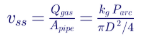
A control philosophy tuned only for the all-in-service case can fail under credible outages. Studies must cover the full SCR range expected over the project's life, including future retirements of synchronous generation, which steadily reduce short-circuit strength in many US regions.
4.5 The other side of AC voltage control
AC voltage control is not automatically stable. In weak grids:
- high voltage-control gains interact with the PLL and network impedance, creating oscillations in the 1 to 20 Hz range;
- multiple devices regulating the same bus — the HVDC terminal, a STATCOM, nearby wind or solar plants — can fight unless voltage droop or coordinated settings are used;
- the PLL itself becomes less stable as SCR falls.
Grid-forming VSC control, which creates an internal voltage rather than following one, is increasingly specified for very weak connections and offshore wind hubs. In every case, EMT studies with vendor control code are required to confirm stability.
5. Inter-area oscillation damping
5.1 Inter-area modes in North America
Large interconnections exhibit inter-area electromechanical modes, typically between about 0.1 and 0.8 Hz, in which groups of generators in one region swing against groups in another. The Western Interconnection has well-known north–south modes around 0.2 to 0.4 Hz; the Eastern Interconnection has lower-frequency modes across its vast footprint. These modes are often lightly damped and are monitored with synchrophasor-based oscillation detection.
5.2 How HVDC can damp oscillations
An HVDC link in parallel with an AC corridor, or connecting two areas, can modulate its active power in phase with the oscillating speed difference between the areas, adding damping torque:

where G(s) includes washout, lead–lag compensation and limits. Input signals can be local (AC line power or bus frequency) or wide-area (synchrophasor frequency or angle differences).
5.3 Worked example: Keentel's two-area model
Keentel modeled two equal areas connected by an AC tie and a parallel HVDC link, with an inter-area mode at about 0.39 Hz.
| Configuration | Damping ratio of inter-area mode | Tie-line oscillation after 10 s |
|---|---|---|
| Terminal 1 Vdc control, terminal 2 constant P | About 1.9% (from natural system damping only) | Still oscillating at about ±0.1 pu |
| Terminal 1 Vdc control, terminal 2 P with POD | Well damped | Below 0.002 pu |
The DC voltage stays at 1.0 pu in both cases — the Vdc terminal does its job of balancing power — but only the POD loop damps the AC mode. Damping ratios below about 3% to 5% are commonly considered inadequate in planning studies, so a POD loop can be an important system benefit of an HVDC project.
5.4 POD design considerations
| Consideration | Guidance |
|---|---|
| Signal selection | Choose signals with high observability of the target mode; wide-area signals improve observability but require communication redundancy |
| Phase compensation | Tune lead-lag blocks so modulation is in phase with speed deviation at the mode frequency |
| Gain | High enough to damp the target mode without exciting other modes or torsional interactions |
| Limits | Limit modulation to a fraction of rating to preserve scheduled transfer |
| Robustness | Test across operating conditions, outages and loss of communication |
| Interaction with generator stabilizers | Coordinate with existing power system stabilizers |
5.5 Worked example: estimating POD gain from modal residues
Modal analysis of a linearized system gives each mode as an eigenvalue λ = σ + jω. A POD controller with gain K shifts the target mode approximately by:

where R is the residue of the transfer function from the HVDC power modulation input to the selected feedback signal, after phase compensation. Suppose the inter-area mode is λ = −0.047 + j2.45 (0.39 Hz, 1.9% damping) and the compensated residue is R = −0.02 + j0.01 per unit gain:
| POD gain K | Shifted eigenvalue | Damping ratio |
|---|---|---|
| 0 | −0.047 + j2.45 | 1.9% |
| 5 | −0.147 + j2.50 | 5.9% |
| 10 | −0.247 + j2.55 | 9.6% |
| 20 | −0.447 + j2.65 | 16.6% |
A gain giving roughly 10% damping is often a practical target, leaving margin for operating-condition changes without demanding excessive modulation. The linear estimate must be confirmed with time-domain simulation, including limits, and checked for adverse effects on other modes.
6. AC fault ride-through
6.1 What happens during a receiving-end fault
When the AC voltage at the receiving (inverter) terminal falls, its active power capability falls with it:

If the fault drops voltage to 0.2 pu and the converter prioritizes reactive current, very little active power can be exported. The sending terminal, unaware, keeps injecting power into the DC system, and DC voltage rises at a rate set by the imbalance and the DC stored energy.
6.2 Worked example: DC overvoltage in Keentel's model
| Strategy | Peak DC voltage | Outcome |
|---|---|---|
| Rectifier keeps scheduled P, no chopper | Exceeds 1.1 pu within about 17 ms; reaches 1.4 pu at 80 ms into the fault | Converter blocks on DC overvoltage; transfer lost |
| Rectifier reduces P when DC voltage exceeds 1.03 pu (DC-voltage droop override) | 1.097 pu | Rides through; power restored after fault |
| DC chopper (braking resistor) absorbs surplus power above 1.05 pu | 1.069 pu | Rides through; sending-end AC system unaffected |
The sending-end response matters: with DC-voltage droop at the rectifier, the sending AC system sees a sudden loss of export — effectively a generation surplus — which can itself be a disturbance, especially for offshore wind or weak sending systems. A DC chopper isolates the sending system from the receiving-end fault, which is why choppers are standard on offshore wind HVDC links.
6.3 Worked example: sizing a DC chopper
For a 1,000 MW link at ±320 kV (640 kV pole to pole), with a design fault duration of 150 ms at full power:
| Quantity | Calculation | Result |
|---|---|---|
| Chopper power | Rated transfer | 1,000 MW |
| Resistance (pole to pole) | V² ÷ P = 640² ÷ 1,000 | ≈ 410 Ω |
| Energy per event | 1,000 MW × 0.15 s | 150 MJ |
| Thermal design | Multiple consecutive events per specification | Often several hundred MJ to over 1 GJ total capability |
Actual designs include margins for fault duration, consecutive faults (for example, reclosing onto a fault) and the wind farm's own fault ride-through behavior.
6.4 Current limiting and reactive current priority
During AC faults, the converter's limited current must be shared between active and reactive components. For transmission-connected inverter-based resources, IEEE 2800-2022 specifies reactive current injection during low-voltage ride-through, and its scope includes VSC-HVDC systems that connect inverter-based resources. Transmission providers and ISO/RTOs specify ride-through requirements for HVDC terminals in interconnection agreements. Practical design choices include:
- reactive current priority during faults to support AC voltage;
- fast active power ramp-up after fault clearing, limited to avoid stressing a weak AC system;
- PLL design and freezing logic that maintains synchronization through phase jumps;
- negative-sequence current control for unbalanced faults.
6.5 The role of the outer loop during faults
Outer loops are slow compared with the fault event. During the fault itself, the inner current loop, current limiter, PLL and DC protection dominate behavior. Outer-loop choice matters mainly for:
- what the converter tries to do as voltage collapses (keep power, or support voltage);
- how quickly and smoothly it recovers after fault clearing;
- which terminal is responsible for DC voltage when one AC side is faulted.
6.7 VSC versus LCC fault behavior
Line-commutated HVDC relies on the AC voltage to commutate thyristor valves. AC faults and voltage dips at the inverter can cause commutation failure, momentarily collapsing DC power transfer at both ends. VSC-HVDC does not commutate against the AC voltage, so it does not suffer commutation failure and can keep supporting AC voltage during faults. When VSC and LCC links terminate near each other, the VSC terminal's reactive support can reduce the LCC link's risk of commutation failure — an interaction worth studying explicitly.
6.8 Worked example: power recovery after fault clearing in a weak system
After a fault clears, active power should ramp back quickly to limit the disturbance to both AC systems, but a step back to full power at a weak bus can depress voltage. For a terminal at SCR 1.8 transferring 0.8 pu, Keentel's model shows that recovering active power over about 0.5 s while AC voltage control supplies reactive power keeps the bus within about 1.0 to 1.07 pu. A faster ramp would reduce the energy lost during recovery but would require more reactive support and could excite control interactions. Transmission providers increasingly specify recovery times for inverter-based resources (for example, IEEE 2800 sets active power recovery expectations), and HVDC terminals should be designed to meet or exceed them.
6.9 Unbalanced faults and negative-sequence control
Most AC faults are unbalanced. During a single-line-to-ground or line-to-line fault, the converter AC bus contains negative-sequence voltage, which produces a second-harmonic (120 Hz) ripple in active power and DC voltage unless the converter controls negative-sequence current. Common strategies:
| Strategy | Effect |
|---|---|
| Suppress negative-sequence current | Balanced converter currents; simple; leaves 120 Hz power ripple and does not help the AC system |
| Inject negative-sequence current per grid code | Supports correct operation of AC protection and reduces negative-sequence voltage; IEEE 2800 specifies negative-sequence current behavior for inverter-based resources |
| Eliminate active power ripple | Keeps DC voltage smooth; requires unbalanced currents within the current limit |
The choice affects AC line protection near the terminal — directional and distance elements rely on negative-sequence quantities — and must be coordinated with the transmission owner's protection engineers.
7. Frequency support for low-inertia systems
7.1 The island problem
An island with little synchronous generation — an isolated grid, a renewable-rich region connected by HVDC, or an offshore network — has low inertia, so a generation loss produces a high rate of change of frequency:
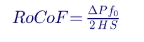
For a 500 MW island with H = 2 s losing 100 MW:

7.2 How HVDC provides support
| Mechanism | Description | Energy source |
|---|---|---|
| P–f droop | Terminal power changes in proportion to island frequency deviation | Remote AC system, through the link |
| Synthetic inertia | Power proportional to RoCoF | Remote system and DC stored energy |
| Emergency power control | Pre-set power steps triggered by events | Remote system |
| Grid-forming control | Converter sets island frequency and voltage | Remote system; terminal acts as the island's main source |
7.3 Worked example: DC stored energy is not the answer
With Hdc = 0.04 s on a 300 MW terminal, DC stored energy is about 12 MJ. The island's rotating kinetic energy is 2 s × 500 MW = 1,000 MJ. DC stored energy is about 1.2% of the island's inertia — and using it means letting DC voltage fall, which the DC controls must prevent. Frequency support must come from power transferred from the main grid.
7.4 Worked example: Keentel's island model
| Configuration | Frequency nadir | Settling frequency | HVDC response |
|---|---|---|---|
| HVDC at fixed P | 56.6 Hz (would trigger extensive under-frequency load shedding) | 59.1 Hz | None |
| HVDC with 2% P–f droop | 59.5 Hz | 59.7 Hz | +99 MW (limited by headroom) |
The droop response is limited by converter headroom: a terminal already near its rating cannot help. Reserving headroom for frequency support is a planning and commercial decision. In the US, NERC BAL-003 frequency response obligations, regional under-frequency load shedding programs and ride-through requirements (NERC PRC-024 and PRC-029) define the frequency envelope that islands and their HVDC links must respect.
7.5 When there is no synchronous generation
If the island has no synchronous generators — an offshore wind collector network, for example — the HVDC terminal must be grid-forming: it sets the AC voltage and frequency for the island, and the wind turbines follow it. In that case, "frequency support" is inherent in the control: the terminal's AC frequency is a control output, and power balance is maintained through the DC link and the onshore terminal's DC voltage control.
7.6 Worked example: headroom needed for a nadir target
For a first-order estimate, the frequency nadir in a low-inertia system depends on how much power can be delivered before frequency falls to the limit. Ignoring local governors, if the HVDC delivers ΔPH within time tr after a generation loss ΔPloss, the frequency fall during the response time is approximately:

With ΔPloss = 100 MW, H = 2 s, S = 500 MW and a linear HVDC ramp to 100 MW in 0.3 s, the deficit integral is 100 × 0.3 ÷ 2 = 15 MW·s, giving Δf ≈ 60 × 15 ÷ 2,000 ≈ 0.45 Hz — close to the 0.47 Hz nadir deviation in Keentel's simulation. The HVDC link must therefore hold at least 100 MW of headroom and respond within a few hundred milliseconds to keep this island above a 59.3 Hz load-shedding threshold.
8. Choosing outer loops: a systematic approach
8.1 Decision table
| System condition | Recommended active-axis control | Recommended reactive-axis control | Supplementary |
|---|---|---|---|
| Strong AC at both ends, point-to-point | P at one end, Vdc at the other | Q or Vac per transmission provider needs | Frequency droop if required |
| Weak AC at one end | Vdc at the stronger end often preferred | Vac at the weak end (carefully tuned) | Consider grid-forming at weak end |
| Parallel to a lightly damped AC corridor | P at one end, Vdc at the other | Vac or Q | POD |
| Low-inertia island | Frequency droop at island terminal, or grid-forming | Vac | Emergency power control |
| Offshore wind export | Grid-forming offshore; Vdc onshore | Vac offshore; Vac or Q onshore | DC chopper; frequency coupling if required |
| Multi-terminal DC grid | DC-voltage droop at several terminals | Vac or Q | Coordinated master control |
8.2 Coordination questions
- Which terminal controls DC voltage in normal operation, and what happens if that terminal's AC side is faulted?
- How are current limits shared between active and reactive current during faults?
- What are the AC voltage control gains and droops relative to nearby devices?
- What supplementary controls are required by the transmission provider (POD, frequency response, runback)?
- How do controls transition between modes (for example, after a terminal blocks)?
- What protection settings (DC overvoltage, AC overvoltage, frequency) must coordinate with the controls?
8A. Looking ahead: multi-terminal grids and grid-forming HVDC
8A.1 Multi-terminal DC grids
Several US offshore wind and interregional proposals contemplate multi-terminal or meshed DC systems that connect multiple offshore platforms or several onshore points. In these systems, outer-loop design becomes a coordination problem:
| Design element | Multi-terminal consideration |
|---|---|
| DC voltage control | Shared by droop among several terminals, with a master or distributed secondary control restoring schedules |
| Power flow control | Each terminal's set point interacts with the others through the DC network |
| DC fault handling | DC breakers or fault-blocking converters needed to avoid losing the entire DC grid |
| Interoperability | Converters from different vendors must work together; common interfaces and functional specifications are needed |
| Protection | Fast DC fault detection and selective clearing within milliseconds |
Interoperability is an emerging challenge in North America: if each converter's controls are proprietary, integrating new terminals into an existing DC grid requires extensive multi-vendor studies.
8A.2 Grid-forming HVDC terminals
Grid-forming control is already standard for offshore wind HVDC terminals that energize and hold the offshore AC network. Onshore, grid-forming VSC terminals can provide voltage-source behavior to weak AC systems, inherent fast frequency and voltage response, and black start capability. Their challenges are the same as other grid-forming resources: current limiting during faults, coordination with protection, and interaction with nearby converters and synchronous machines. NERC has published guidance on grid-forming functional specifications, and several ISO/RTOs are evaluating grid-forming requirements for new inverter-based resources and HVDC links.
8A.3 Implications for outer-loop selection
As grid-forming control spreads, the classic outer-loop menu — P, Q, Vdc, Vac, f — evolves into a choice of synchronization philosophy (grid-following or grid-forming) plus the active and reactive objectives layered on top. The principles in this guide still apply: one or more terminals must balance DC power, damping needs a damping signal, faults are DC energy events, and frequency support depends on headroom and the strength of the remote system.
9. Modeling and study requirements
9.1 RMS versus EMT
| Phenomenon | Positive-sequence RMS | EMT |
|---|---|---|
| Inter-area oscillations and POD design | Appropriate | For validation |
| Frequency response | Appropriate | For validation |
| Steady-state voltage control | Appropriate | — |
| Weak-grid control interactions | Inadequate | Required |
| Fault ride-through, current limiting, PLL | Approximate | Required |
| DC protection, chopper sizing, DC faults | Inadequate | Required |
| Sub-synchronous control interaction | Inadequate | Required |
| Harmonic and resonance behavior | Inadequate | Required (with frequency scans) |
9.2 US modeling requirements
NERC Reliability Standard MOD-032 requires data for planning models, and NERC reliability guidelines recommend EMT models for inverter-based resources and HVDC in weak areas. FERC Order No. 2023 strengthened model requirements in interconnection procedures. ISO/RTOs typically require vendor-specific EMT models (often in PSCAD) and positive-sequence models for HVDC projects, with model quality checks and benchmarking.
9.3 Model validation
Commissioning tests — step responses of each outer loop, POD tests, frequency response tests and staged fault tests where possible — should be compared with model predictions. NERC MOD-026 and MOD-027 concepts of model verification apply to controls of HVDC systems as part of the planning model data.
9.4 A practical HVDC control study workflow
- Define the system: AC connection points, voltage classes, short-circuit levels under normal and outage conditions, nearby inverter-based resources and synchronous machines.
- Select control philosophy: active-axis and reactive-axis outer loops at each terminal, supplementary controls and mode transitions.
- Screen with RMS models: power flow, voltage control, frequency response, inter-area modes and POD design.
- Detailed EMT studies: weak-grid stability, AC fault ride-through, DC faults, chopper sizing, protection coordination and control interactions with nearby converters.
- Frequency scans: impedance-based screening for resonances and control interactions across frequency.
- Specify: performance requirements in the converter specification — not just hardware ratings, but control behavior, response times and model deliverables.
- Review vendor design: independent verification of vendor studies and models.
- Commission and validate: test each outer loop and compare with models.
- Maintain models: update after firmware or setting changes and after network changes that alter SCR.
10. Protection and control interaction
| Protection | Interaction with outer loops |
|---|---|
| DC overvoltage | Must coordinate with DC voltage control, chopper and fault ride-through logic |
| DC undervoltage | Coordinate with Vdc control and DC fault handling |
| AC overvoltage | Vac control and reactive current must not cause overvoltage after fault clearing, especially at weak buses |
| AC under-/over-frequency | Coordinates with frequency droop and NERC PRC-024/PRC-029 ride-through |
| Converter overcurrent | Current limiter must act before protection |
| AC line protection near the converter | VSC fault current is limited and controlled; distance and directional relays must be set for converter fault characteristics |
Line protection near VSC terminals deserves attention: the converter's controlled, limited fault current — and its negative-sequence behavior — can affect directional and distance elements. Protection studies with EMT models are increasingly expected.
11. Commissioning and operation
11.1 Typical outer-loop tests
| Test | Purpose |
|---|---|
| P step and ramp tests | Verify active power control response and limits |
| Vdc step tests | Verify DC voltage control and coordination between terminals |
| Q and Vac step tests | Verify reactive and voltage control, including droop |
| Mode transfer tests | Verify smooth transitions between control modes |
| POD tests (where enabled) | Inject probing signals or use ambient data to verify damping contribution |
| Frequency response tests | Verify droop response and headroom |
| Staged AC fault tests (where feasible) | Verify fault ride-through and DC voltage control |
| Converter block and restart tests | Verify recovery sequences |
11.2 Operational considerations
- Mode selection should be documented in operating procedures, with clear rules for when supplementary controls are enabled.
- POD and frequency droop require headroom, which may conflict with commercial scheduling.
- Outages in the AC network change SCR and may require different control settings; some projects implement adaptive tuning.
- Firmware changes require model updates and revalidation.
11.3 Specification checklist for outer-loop performance
Converter specifications often describe hardware in great detail and controls only briefly. Keentel recommends that specifications state, at minimum:
| Item | Example specification content |
|---|---|
| Control modes | Required P, Q, Vdc, Vac, f, POD and grid-forming modes at each terminal, and permitted transitions |
| Performance | Step response rise and settling times for each outer loop across the stated SCR range |
| Weak-grid capability | Minimum SCR for stable operation at full transfer, demonstrated by EMT studies |
| Fault ride-through | Voltage and frequency ride-through envelopes, reactive current injection, post-fault recovery time |
| DC overvoltage control | Chopper rating and energy, or alternative strategy, with design fault scenarios |
| Frequency support | Droop range, deadband, response time and headroom management |
| POD | Inputs, tuning range, limits and test methods |
| Models | Positive-sequence and EMT models with actual control code, documentation and benchmarking |
| Testing | Factory, site and grid compliance tests for each control function |
Clear performance requirements make vendor proposals comparable and give the owner a contractual basis to correct deficiencies.
12. Common misconceptions corrected
| Misconception | Engineering reality |
|---|---|
| "Vdc control damps oscillations." | Vdc control balances power; damping requires POD. |
| "Both terminals on P control causes DC oscillations." | It causes DC voltage drift and a trip; it is not a viable configuration. |
| "Voltage modes automatically ride through faults." | Ride-through depends on current limiting, reactive current priority, choppers and DC voltage coordination. |
| "DC capacitors provide inertia." | Their stored energy is tiny; support comes from the remote AC system. |
| "AC voltage control is always better in weak grids." | It is usually necessary, but must be tuned to avoid control interactions; grid-forming control may be needed. |
| "RMS studies are enough." | EMT studies are needed for faults, weak grids and DC protection. |
| "50 Hz results apply directly." | US systems are 60 Hz; frequency criteria and modal frequencies must be evaluated accordingly. |
13. Key takeaways
- One terminal must control DC voltage, or several must share it by droop.
- Weak grids need AC voltage control or grid-forming, tuned with EMT models.
- Damping needs a damping controller.
- AC faults at the receiving end are DC overvoltage events; plan choppers and coordinated controls.
- Frequency support is power from the other system, limited by headroom.
- Match the study tool to the phenomenon: RMS for slow dynamics, EMT for fast ones.
14. How Keentel Engineering helps
Keentel Engineering supports transmission developers, utilities, offshore wind developers and ISO/RTO stakeholders with HVDC planning, control and interconnection studies, from 4 kV to 765 kV.
| Service | Keentel scope | Outcome |
|---|---|---|
| HVDC feasibility and configuration | VSC versus LCC, point-to-point versus multi-terminal, AC connection points and voltage classes | Sound technical basis for investment |
| Control mode and outer-loop studies | P, Vdc, Q, Vac, frequency and POD strategy; coordination between terminals | Stable, coordinated control philosophy |
| Weak-grid and EMT studies | SCR screening, PSCAD studies with vendor models, grid-forming evaluation | Verified stability at weak connections |
| Fault ride-through and DC protection | AC fault studies, DC chopper sizing, DC overvoltage coordination | Robust ride-through |
| Inter-area oscillation and POD design | Modal analysis, signal selection, POD tuning and robustness | Improved system damping |
| Frequency response studies | Island and low-inertia studies, droop and headroom analysis | Frequency performance within NERC and regional criteria |
| Interconnection and compliance | Model submissions, ISO/RTO study support, IEEE 2800 and NERC requirements | Faster approvals |
| Owner's engineer | Specification review, factory and site test witnessing, model validation | Delivered performance matches the specification |
Why clients choose Keentel Engineering
- Control-aware power system engineering: we understand converter controls as well as the networks they connect.
- EMT and RMS depth: the right tool for each phenomenon.
- Practical US experience: ISO/RTO requirements, NERC standards and US voltage classes.
- Vendor-neutral perspective: independent review of vendor designs and models.
- Licensed professional engineering: a Florida-registered firm with offices in Tampa, Austin, Sacramento and Baltimore, supporting projects nationwide.
Planning a VSC-HVDC link, offshore wind export system or weak-grid interconnection? Talk to Keentel Engineering at (813) 389-7871, contact@keentelengineering.com, or book a 15-minute scoping call at calendly.com/keentel-engineering/15min.
Part C — Case Studies
The following are illustrative scenarios based on conditions typical of US HVDC projects. They show how Keentel Engineering approaches outer-loop control decisions; site details are generalized and figures are rounded.
Case Study 1 — Interregional VSC link into a weak 345 kV bus
Situation. A developer plans a 1,000 MW VSC-HVDC link delivering renewable energy into a 345 kV substation whose short-circuit capacity falls to about 1,800 MVA under credible outages — an SCR of 1.8. The initial specification calls for constant reactive power at the receiving end.
Analysis. Keentel's studies show that with fixed reactive power the receiving bus would sit near 0.85 pu at full transfer under the outage condition, outside the transmission owner's voltage criteria, and that remote faults could drive the operating point beyond the converter's capability. EMT studies with the vendor's model show that AC voltage control holds voltage but oscillates at about 8 Hz with the initial gains.
Engineered solution. Keentel recommends AC voltage control with a reactive droop coordinated with a nearby STATCOM, retuned voltage-control and PLL gains, and DC voltage control at the stronger sending terminal. Grid-forming capability is specified as an option for future network weakening.
Outcome. The revised control philosophy meets voltage criteria under all studied outages, and EMT studies show well-damped responses. The transmission provider accepts the study and the control requirements are written into the interconnection agreement.
Case Study 2 — Offshore wind export: receiving-end faults and DC overvoltage
Situation. An offshore wind project plans an 1,100 MW VSC-HVDC export system to a 345 kV onshore substation. Early studies assume the onshore terminal controls DC voltage and the offshore terminal is grid-forming.
Analysis. Keentel's EMT studies show that close-in onshore AC faults collapse the onshore terminal's export capability while the wind farm continues producing, driving DC voltage beyond protection limits within about 20 ms. Reducing wind farm output through the offshore grid frequency is too slow to prevent the overvoltage.
Engineered solution. Keentel specifies a DC chopper sized for full power for the specified fault duration, with energy capability for consecutive faults, and coordinates chopper thresholds with DC overvoltage protection and the wind turbines' frequency response for longer events.
Outcome. The system rides through all specified onshore faults without blocking, and the wind farm sees no disturbance from onshore AC faults.
Case Study 3 — HVDC link providing frequency support to a low-inertia region
Situation. A utility serving a region with high renewable penetration and limited synchronous generation relies on a VSC-HVDC link for imports. Studies of the largest credible generation loss show frequency nadirs below the first under-frequency load shedding stage when the link runs at fixed power.
Analysis. Keentel models the region's frequency response with and without P–f droop on the HVDC link. Droop sharply improves the nadir, but only when the link operates with at least 100 MW of headroom. At high import schedules, headroom disappears.
Engineered solution. Keentel recommends a 2% frequency droop with a minimum headroom requirement during low-inertia hours, combined with fast frequency response from battery storage when the link is near full import. Operating procedures define when the headroom requirement applies.
Outcome. Studies show frequency nadirs above the first load-shedding stage for all credible contingencies, and the utility gains a coordinated frequency response strategy using existing assets.
Part D — Technical FAQ: VSC-HVDC Outer-Loop Control
The control layer that sets current references for the inner current loop based on objectives such as active power, DC voltage, reactive power, AC voltage or frequency.
Because DC voltage reflects power balance in the DC system. If no terminal regulates it, any mismatch integrates into a drift that leads to protection blocking.
DC voltage drifts. In Keentel's model, a 1% mismatch drives DC voltage to 1.15 pu in about 2.6 seconds.
Yes. In multi-terminal systems, DC-voltage droop at several terminals shares imbalances in proportion to droop gains.
Fixed reactive power cannot hold voltage at low SCR. AC voltage control supplies the reactive power needed, as in Keentel's example where 0.19 pu of reactive power held 1.0 pu at SCR 1.8.
Yes. High gains can interact with the PLL and network impedance. EMT studies with vendor models are needed to tune it.
No. It balances power. Damping requires a power oscillation damping controller that modulates active power.
Local signals such as AC line power or bus frequency, or wide-area synchrophasor signals such as frequency or angle differences between areas.
Roughly 0.1 to 0.8 Hz, with well-known Western Interconnection modes around 0.2 to 0.4 Hz.
The faulted terminal cannot export power while the sending terminal keeps injecting it, so energy accumulates in the small DC stored energy and voltage rises within milliseconds.
With a total DC inertia constant of 0.08 s and a 1 pu imbalance, it rises from 1.0 to 1.1 pu in about 17 ms.
A controlled braking resistor that absorbs surplus DC power during receiving-end faults, protecting the DC system without disturbing the sending end.
For rated power over the specified fault duration and number of consecutive events; for example, 1,000 MW at ±320 kV needs about 410 Ω and 150 MJ per 150 ms event.
During faults, the current limit is allocated first to reactive current to support AC voltage, with active current reduced accordingly.
Only a tiny amount: about 1% of a 500 MW island's inertia in Keentel's example. Real frequency support comes from power drawn from the remote AC system.
It increases imported power in proportion to frequency deviation, limited by headroom. In Keentel's model it raised the nadir from 56.6 Hz to 59.5 Hz.
Control that sets AC voltage magnitude and frequency directly, required when the AC side has no other source, such as an offshore wind collector network.
For inter-area oscillations, frequency response and steady-state voltage control. EMT is required for faults, weak-grid interactions and DC protection.
IEEE 2800-2022 for VSC-HVDC connecting inverter-based resources, NERC TPL-001, MOD-032, PRC-024, PRC-029 and BAL-003, FERC Order No. 2023 model requirements and ISO/RTO interconnection requirements.
Selecting modes for normal operation without studying what happens when one AC side is faulted, weakened or islanded.
References and Further Reading
Links were current at publication (October 2026).
- IEEE Std 2800-2022, Standard for Interconnection and Interoperability of Inverter-Based Resources Interconnecting with Associated Transmission Electric Power Systems. IEEE.
- IEEE Std 1204, Guide for Planning DC Links Terminating at AC Locations Having Low Short-Circuit Capacities. IEEE.
- IEEE/CIGRE, Definition and Classification of Power System Stability — Revisited and Extended (2021). IEEE Transactions on Power Systems.
- CIGRE Technical Brochure 269, VSC Transmission; CIGRE Technical Brochure 604, Guide for the Development of Models for HVDC Converters in an HVDC Grid. CIGRE.
- NERC Reliability Standards TPL-001, MOD-032, MOD-026/027, PRC-024, PRC-029 and BAL-003; NERC reliability guidelines on EMT modeling and low short-circuit strength systems. North American Electric Reliability Corporation.
- FERC Order No. 2023, Improvements to Generator Interconnection Procedures and Agreements. Federal Energy Regulatory Commission.
- P. Kundur, Power System Stability and Control. McGraw-Hill.
- D. Jovcic and K. Ahmed, High Voltage Direct Current Transmission: Converters, Systems and DC Grids. Wiley.
- L. Zhang, L. Harnefors and H.-P. Nee, "Power-Synchronization Control of Grid-Connected Voltage-Source Converters," IEEE Transactions on Power Systems, 2010.
Disclaimer
This article is general technical information for educational purposes. It is not engineering advice for any specific project and does not create a professional relationship. Keentel Engineering's simulation results come from simplified reduced-order models with illustrative parameters; actual HVDC behavior depends on vendor-specific converter controls, protection, network conditions and operating practices and must be verified with validated vendor models, including EMT studies. Designs must follow current IEEE standards, NERC requirements, transmission provider and ISO/RTO criteria and project-specific engineering analysis, sealed by a licensed professional engineer where required.
Case studies are illustrative scenarios based on typical project conditions, not records of specific client projects. Figures are rounded and indicative.
IEEE, NERC, FERC, CIGRE, PSCAD™ and other names are the property of their respective owners. Keentel Engineering is not affiliated with or endorsed by these organizations or any equipment vendor.
| Office | Address | Phone |
|---|---|---|
| Head Office — Tampa | 400 N Ashley Dr STE #2600, Tampa FL 33602 | (813) 389-7871 |
| Austin | 5900 Balcones Drive STE 100, Austin TX 78731 | (512) 591-0752 |
| Sacramento | 1401 21st St Ste R, Sacramento CA 95811 | (916) 913-4524 |
| Baltimore | 306 W Redwood St STE 200, Baltimore MD 21201 | (410) 225-2181 |

About the Author:
Sandip "Sonny" R. Patel, P.E.
IEEE Senior Member · Founder & CEO, Keentel Engineering
In 1995, Sonny Patel earned his Electrical Engineering degree from the University of Illinois. But degrees don't build legacies — action does.
For three decades, he has worked the power industry from every side of the table: 16 years as a utility engineer at Exelon/Commonwealth Edison; generation leadership across hydroelectric, industrial steam turbine, and a 9 GW renewable fleet; NERC Regional Entity Senior Compliance Engineer and Audit Team Lead, auditing some of the nation's largest utilities; and testing and commissioning lead on equipment up to 765 kV — the very top of the North American grid.Utility. Generator. Regulator. Consultant. Few engineers have seen all four seats. Fewer still have sat in them.
His experience spans nuclear, hydro, conventional generation, renewables, oil and gas, mining — and today's data centers, where he is authoring a three-book series on data center design. He is a Licensed Professional Engineer in six states and a Licensed Electrical Contractor in Florida (Unlimited EC) — he doesn't just design the work; he's qualified to stand behind its execution.Today, as Founder and CEO of Keentel Engineering, Sonny leads a nationwide team of engineers delivering substation design, power system studies, NERC compliance, and commissioning — done right, coast to coast.Three decades. Every side of the table. One standard: accountable engineering.
Services

Let's Discuss Your Project
Let's book a call to discuss your electrical engineering project that we can help you with.
About the Author:
Sandip "Sonny" R. Patel, P.E.
IEEE Senior Member · Founder & CEO, Keentel Engineering
In 1995, Sonny Patel earned his Electrical Engineering degree from the University of Illinois. But degrees don't build legacies — action does.
For three decades, he has worked the power industry from every side of the table: 16 years as a utility engineer at Exelon/Commonwealth Edison; generation leadership across hydroelectric, industrial steam turbine, and a 9 GW renewable fleet; NERC Regional Entity Senior Compliance Engineer and Audit Team Lead, auditing some of the nation's largest utilities; and testing and commissioning lead on equipment up to 765 kV — the very top of the North American grid.
Utility. Generator. Regulator. Consultant. Few engineers have seen all four seats. Fewer still have sat in them.
His experience spans nuclear, hydro, conventional generation, renewables, oil and gas, mining — and today's data centers, where he is authoring a three-book series on data center design. He is a Licensed Professional Engineer in six states and a Licensed Electrical Contractor in Florida (Unlimited EC) — he doesn't just design the work; he's qualified to stand behind its execution.
Today, as Founder and CEO of Keentel Engineering, Sonny leads a nationwide team of engineers delivering substation design, power system studies, NERC compliance, and commissioning — done right, coast to coast.Three decades. Every side of the table. One standard: accountable engineering.
Leave a Comment
Thank you for contacting us.
We will get back to you as soon as possible.
We will get back to you as soon as possible.
Oops, there was an error sending your message.
Please try again later.
Please try again later.
Related Posts
By SANDIP R PATEL
•
October 24, 2026
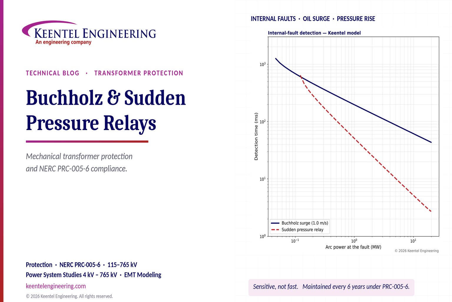
Learn how Buchholz and sudden pressure relays protect transformers, detect internal faults, and meet NERC PRC-005-6 maintenance requirements.
By SANDIP R PATEL
•
October 23, 2026
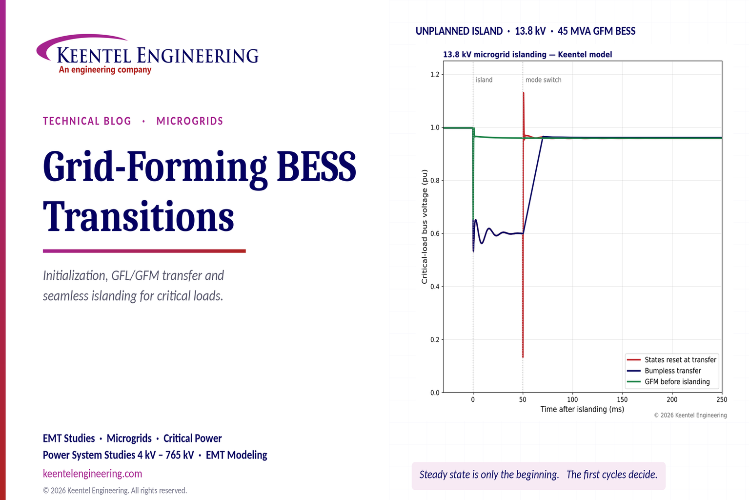
Explore grid-forming BESS initialization, GFL-to-GFM transitions, seamless islanding, EMT simulations, current limiting and microgrid protection.
By SANDIP R PATEL
•
October 23, 2026
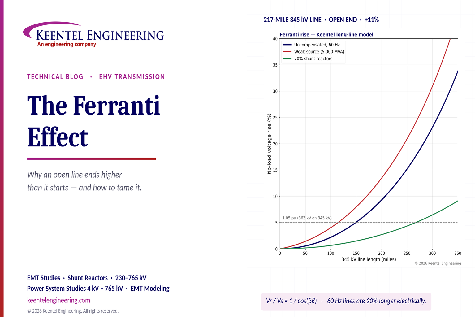
Explore the Ferranti effect in EHV transmission lines: voltage rise, 345 kV examples, switching overvoltages, shunt reactor sizing and mitigation.
By SANDIP R PATEL
•
October 23, 2026
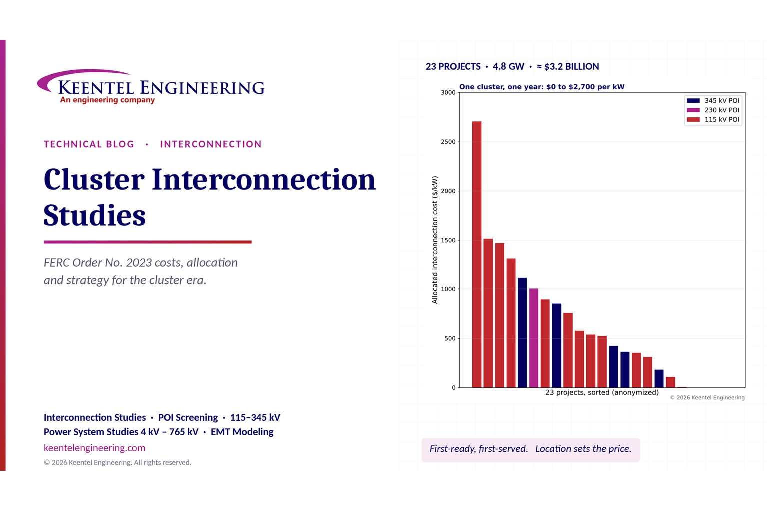
Explore cluster interconnection studies under FERC Order 2023, including network upgrades, cost allocation, withdrawal penalties and developer strategy.
By SANDIP R PATEL
•
October 21, 2026
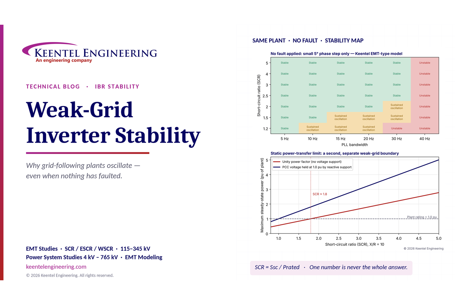
Learn why grid-following inverters become unstable without grid faults. Explore SCR, PLL interactions, EMT studies, grid strength, and mitigation.
By SANDIP R PATEL
•
October 21, 2026
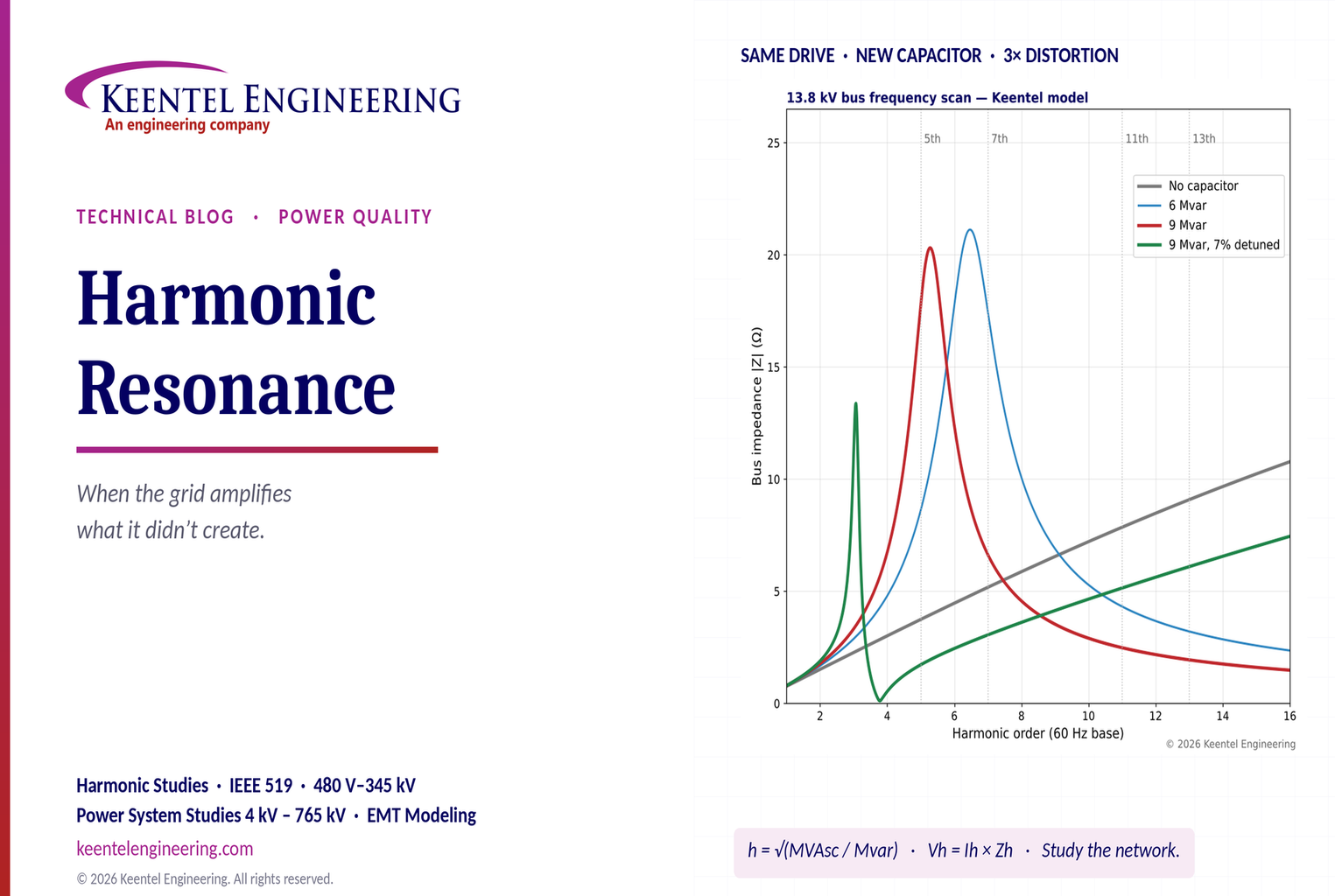
Learn how harmonic resonance amplifies distortion in power systems. Explore capacitor banks, detuned reactors, frequency scans, and IEEE 519 solutions.
By SANDIP R PATEL
•
October 20, 2026
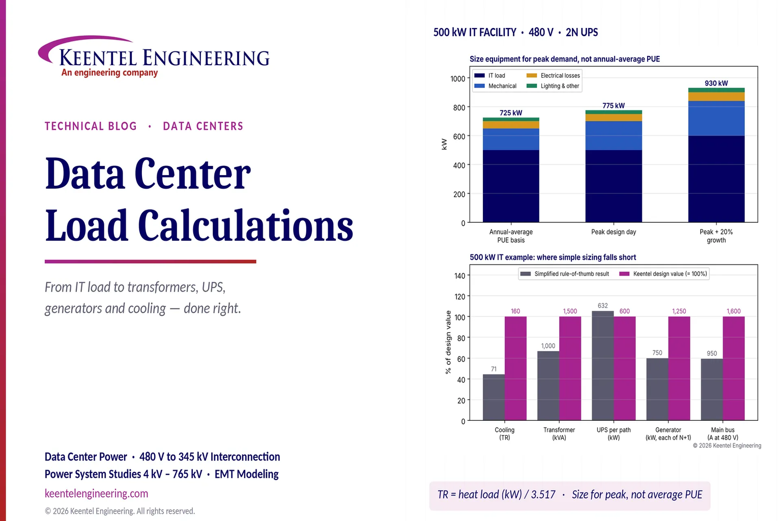
Learn data center electrical load calculations, including IT demand, PUE, UPS and generator sizing, cooling loads, redundancy, and worked US examples.
By SANDIP R PATEL
•
October 20, 2026
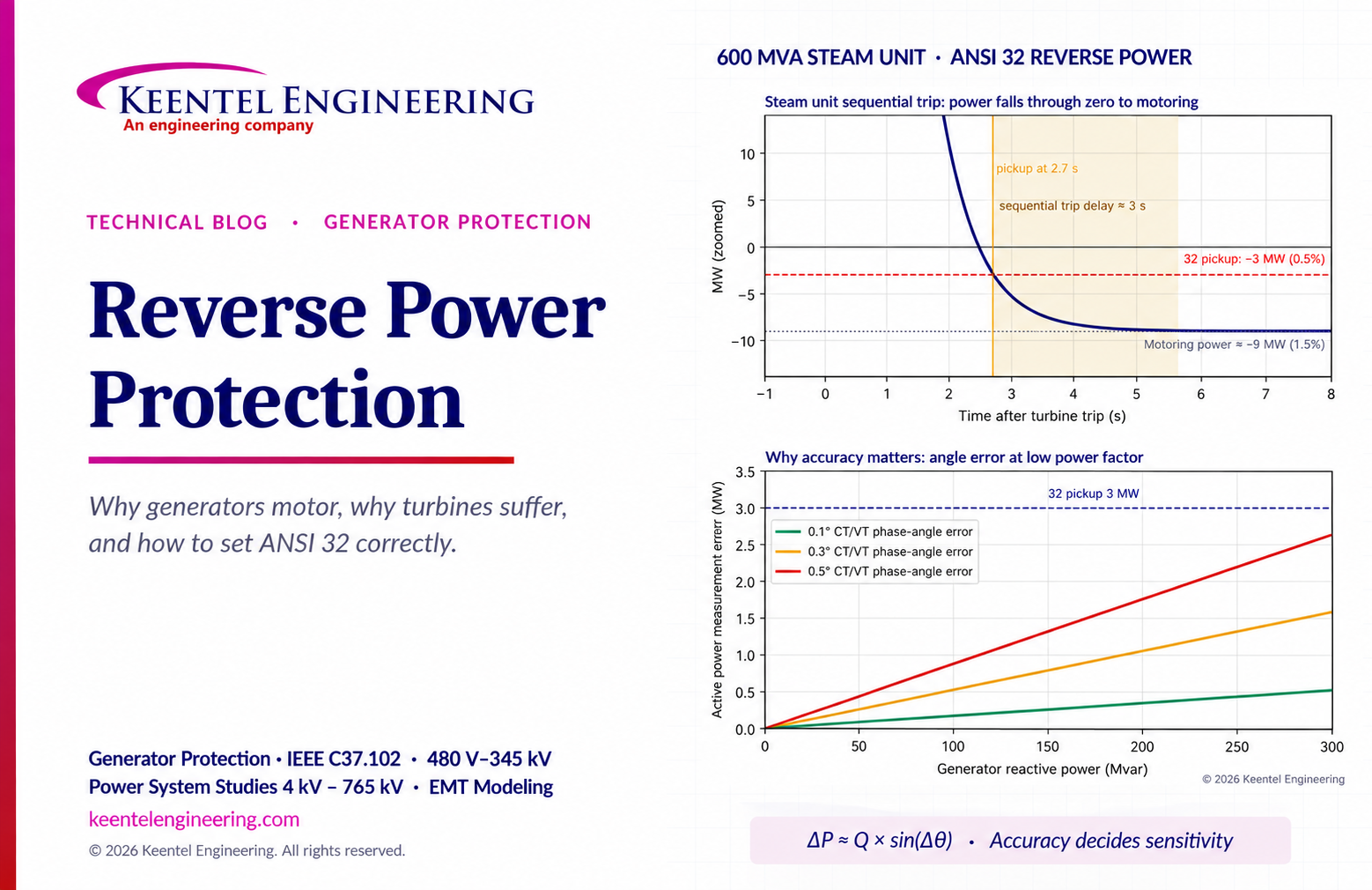
Learn reverse power protection (ANSI 32), generator motoring, relay pickup settings, time delays, sequential tripping and testing for US power plants.
By Team 2 Dexora
•
October 20, 2026
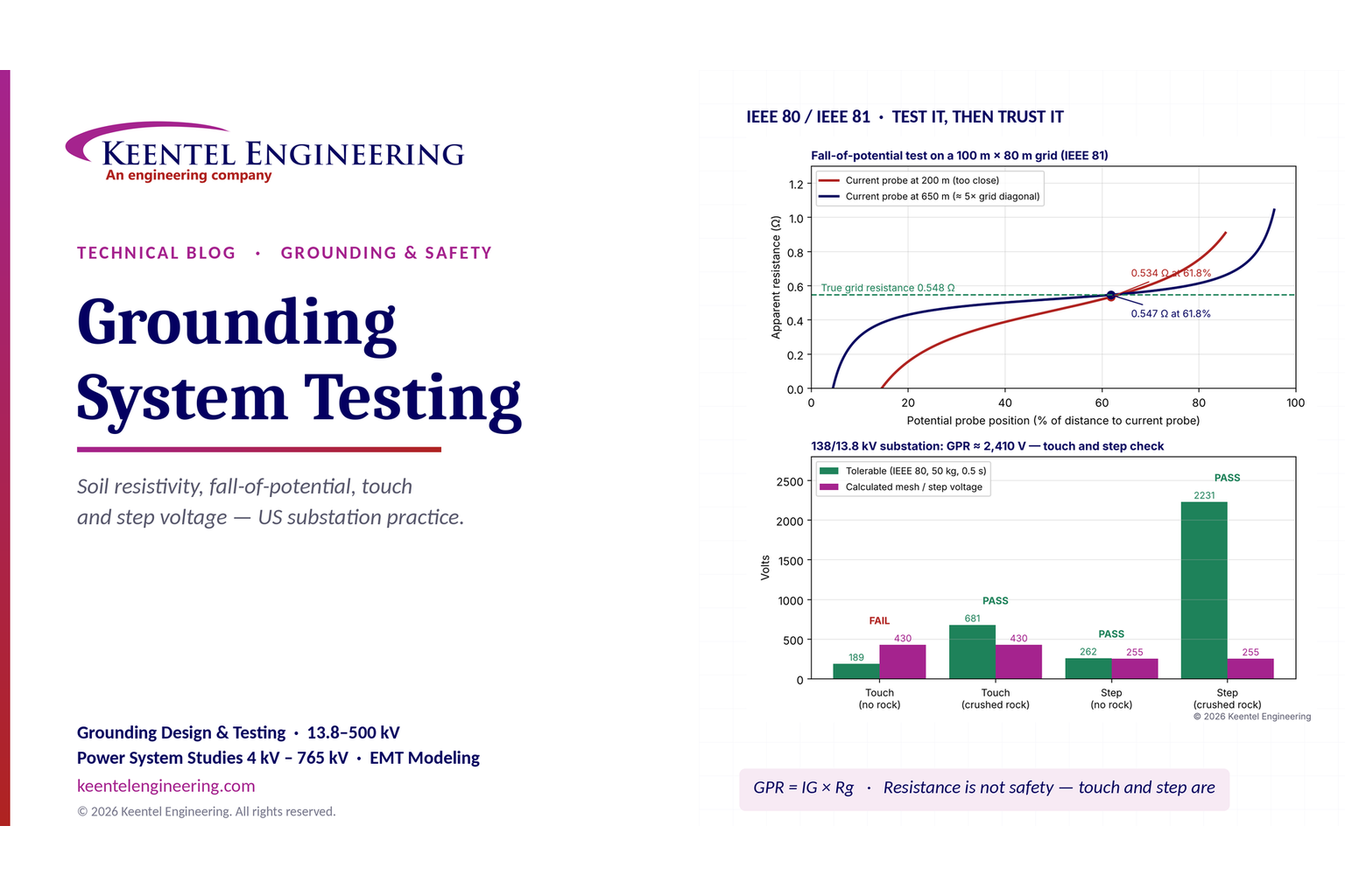
Explore grounding system testing with Keentel Engineering. Learn IEEE 80/81 methods, soil resistivity, ground resistance, and touch and step voltage safety.