A Coordinated Electric System Interconnection Review—the utility’s deep-dive on technical and cost impacts of your project.
Challenge: Frequent false tripping using conventional electromechanical relays
Solution: SEL-487E integration with multi-terminal differential protection and dynamic inrush restraint
Result: 90% reduction in false trips, saving over $250,000 in downtime
The three operating regions you have to design to
| Device | Output vs voltage | Response | Best suited to | Main limitations |
|---|---|---|---|---|
| Mechanically switched capacitor or reactor | Proportional to voltage squared | Seconds; discrete steps; limited switching operations per day | Steady-state reactive supply, voltage profile, loss reduction | No dynamic capability; step voltage change on switching; capability collapses when most needed |
| Static var compensator | Capacitive branches proportional to voltage squared | A few cycles; continuously controllable | Continuous control where cost matters and deep voltage support is not the driver | Square-law capability loss; harmonic filters are part of the plant and interact with the network |
| STATCOM | Approximately proportional to voltage — constant current capability | One to two cycles closed loop; converter response faster still | Voltage stability margin, weak interconnections, fast disturbance recovery, flicker and unbalance compensation | Higher capital cost; converter losses; adds a converter and its control dynamics to the network |
| Synchronous condenser | Governed by machine capability and excitation | Excitation response in the hundreds of milliseconds; inherent inertial response instantaneous | System strength and inertia, short-circuit contribution, black start support | Rotating plant with maintenance and losses; slower controlled response than a converter |
| STATCOM with energy storage | Reactive as a STATCOM, plus real power within the storage rating | As STATCOM for reactive; real power limited by storage | Where a real power deficiency is part of the problem | Cost and complexity of the storage; different failure and maintenance profile |
| Stage | Keentel scope | Outcome |
|---|---|---|
| Screening | Series-compensation proximity, radial contingency review, UIF and short-circuit ratio screening, frequency scans | Early identification of which SSO types apply |
| Detailed studies | PSCAD/EMTDC EMT studies with vendor real-code models, impedance-based and frequency-scan analysis | Clear evidence of stability margins or risk |
| Model quality | EMT model review, benchmarking against positive-sequence models, model acceptance support | Models that system operators accept |
| Mitigation | Control retuning recommendations with vendors, SSDC and bypass logic requirements, protection and monitoring specifications | Practical, coordinated solutions |
| Interconnection support | SSR and SSO study reports for ISO and utility requirements, response to reviewer comments | Fewer delays in the interconnection process |
Resilience: designing CDUs to the facility Tier objective
Liquid cooling makes heat removal more critical, not less. Cold plates hold only seconds of thermal buffer. If TCS flow stops, processors throttle or shut down very quickly. Resilience design must therefore cover:
- Pump redundancy: N+1 pumps at minimum, with automatic changeover.
- CDU redundancy: N+1 CDUs on a common TCS header, or 2N CDUs serving A and B manifolds for fault-tolerant designs.
- Power to CDUs: dual-corded CDUs fed from A and B sources, with pumps and controls on UPS power so coolant keeps flowing through a utility failure and generator start. This is the liquid-cooling equivalent of continuous cooling.
- Facility water continuity: chilled water or condenser water must also continue, through thermal storage, UPS-backed pumps or a high enough FWS temperature that the TCS can coast on stored thermal mass for the transfer period.
- Concurrent maintainability: isolation valves so any CDU, pump, filter or manifold section can be serviced without stopping the others.
- Leak management: leak detection, drip trays, automatic isolation valves and procedures for fluid spills.
Electrical engineering considerations
CDUs and liquid-cooling plants are electrical loads with their own design requirements:
- Pump motors and VFDs. Large CDUs use variable-frequency drives on their pump motors. These introduce harmonic current that must be included in the facility's harmonic study and IEEE 519 evaluation.
- Critical mechanical load on UPS. Putting CDU pumps on UPS increases UPS and battery sizing. The mechanical UPS load must be included in redundancy and ride-through calculations.
- Feeder and protection design. Dual feeds, automatic transfer, selective coordination and arc-flash labelling apply to CDU power distribution just as they do to IT power.
- Generator transient response. CDU pumps restarting together after a transfer create motor inrush on the generators. Staged restarts and soft acceleration reduce the step load.
- Load dynamics. AI training loads can swing rapidly between high and low power. Cooling controls must track those swings without temperature overshoot, and electrical systems must handle both the IT and the cooling load changes.
Commissioning a liquid-cooled data hall
- Flush and clean the TCS piping and manifolds to the specified cleanliness, using high-purity flush water.
- Fill and vent with the specified coolant, verifying glycol concentration and chemistry.
- Pressure test for leaks at design and test pressures, including quick-disconnect fittings.
- Verify sensors and controls: flow meters, temperature sensors, pressure transmitters, leak detection and BMS points.
- Load test with heat load banks connected through the cold-plate interfaces or rack manifolds, across the operating range.
- Prove the heat balance on both loops at several load steps, and the approach temperature against the design.
- Test failure scenarios: pump failure, CDU failure, power transfer to generator, valve failure and loss of facility water, confirming temperatures stay within the IT vendor's limits.
How Keentel Engineering helps
Keentel Engineering supports data center owners, developers and EPCs with the electrical engineering that liquid-cooled facilities depend on, and coordinates with the mechanical engineer of record and cooling vendors on the integrated design.
Grid-Forming BESS: Initialization, GFL/GFM Transitions & Microgrid Engineering
October 23, 2026 | Blog
Part A — Grid-Forming BESS Transitions at a Glance
A microgrid can pass every steady-state check — load flow, short-circuit, voltage drop, power factor — and still fail when it matters most: in the first few cycles after the utility disappears or the battery changes control mode. A 13.8 kV grid-forming battery energy storage system (BESS) may look perfectly stable on paper. The real test is what happens when operating conditions change and the critical load is at stake.
Three engineering challenges decide whether a critical microgrid rides through those first cycles:
- Initialization. Mismatches in voltage magnitude, phase angle or controller states between the network solution and the inverter controls create artificial transients at the start of a simulation — and real transients at the moment of a mode change in the field.
- Control transitions. Grid-following (GFL) control regulates current and synchronizes with a phase-locked loop (PLL). Grid-forming (GFM) control creates its own voltage and frequency reference. Switching between them is not a software toggle; controller states, references and outputs must be handed over consistently.
- Seamless transfer. In hospitals, data centers, water utilities and defense installations, a disturbance during islanding can drop process equipment, IT load or life-safety systems. Continuity depends on transfer logic, inverter current limits, protection and the wider power architecture working together.
What Keentel's simulations show
Keentel Engineering modeled a 13.8 kV critical microgrid: a 45 MVA BESS, a 30 MW plus 10 Mvar critical load, and a utility source with 250 MVA of short-circuit capacity. Before islanding, the BESS exports about 11 MW and the utility supplies the remaining 19 MW. The model is a three-phase average-value representation in the dq frame, including network inductance and capacitance dynamics, a droop-based GFM controller and a PLL-based GFL controller.
| Scenario | Peak inverter current | Minimum bus voltage | Time below 0.9 pu | Final state |
|---|---|---|---|---|
| GFM, consistent initialization from load flow | 0.25 pu (steady) | 0.997 pu | 0 ms | Steady from t = 0 |
| GFM, 10° angle mismatch in controller state | 1.23 pu | 0.993 pu | 0 ms | Artificial 1.23 pu spike, decays in about 150 ms |
| Unplanned island, GFL only (no transition) | 0.44 pu | 0.53 pu | Indefinite | Voltage collapses to 0.60 pu; PLL frequency runs away |
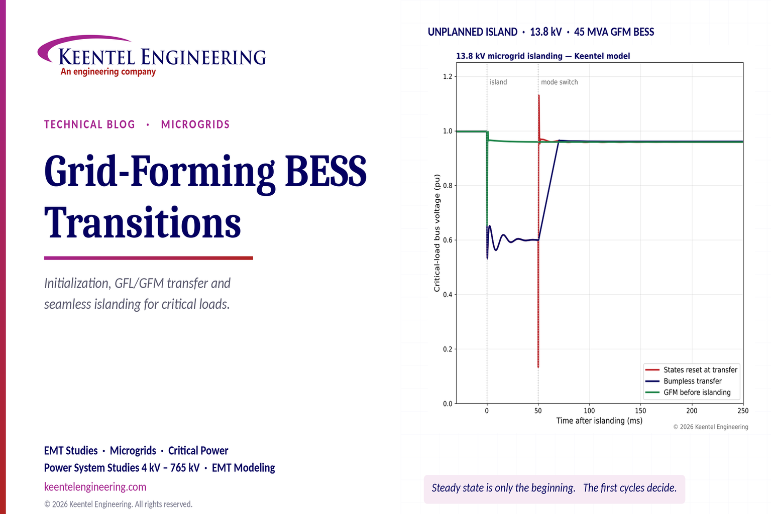
| Island, GFL → GFM after 3 cycles, controller states reset | 0.97 pu | 0.13 pu at transfer | 51 ms | Recovers at 59.55 Hz after a severe notch |
| Island, GFL → GFM after 3 cycles, bumpless transfer | 0.70 pu | 0.53 pu (before transfer) | 67 ms | Recovers smoothly at 59.54 Hz |
| GFM before and after islanding | 0.72 pu | 0.65 pu (under 1 ms) | 0.7 ms | Seamless; 0.96 pu, 59.55 Hz |

Figure 1. Keentel's 13.8 kV microgrid simulations. Panel 1: initialization with and without state consistency. Panels 2 to 4: bus voltage, inverter current and frequency during unplanned islanding with four control strategies.
Four lessons from the simulations
- Initialization errors look like real events. A 10° angle mismatch between the network solution and the grid-forming controller's internal angle produces a 1.23 pu current spike — above a typical 1.2 pu inverter current limit — in a system that is actually operating at 0.25 pu. In a study, that spike can be mistaken for a genuine problem; in the field, an equivalent mismatch at a mode change is a genuine problem.
- A grid-following inverter cannot hold up an island by itself. Once the utility is gone, it has no voltage to follow. In the model, voltage falls to 0.6 pu and the PLL frequency estimate runs away within a few cycles.
- How the transition is made matters as much as when. Resetting controller states at transfer produces a voltage notch to 0.13 pu and a 0.97 pu current swing. Aligning the grid-forming angle, voltage and power states with the measured conditions removes the notch and limits the current to 0.70 pu.
- The best transition is often no transition. Operating the BESS as grid-forming before islanding gives a dip of less than one millisecond. Every transition scheme that waits for islanding detection leaves the critical load at reduced voltage for at least the detection time — 33 ms even with one-cycle detection — which is outside the ITIC (CBEMA) tolerance curve for much IT and process equipment.
Engineering review of a typical published study setup
Keentel reviewed a typical published simulation setup for a grid-forming BESS on a 13.8 kV microgrid. The concepts are sound, but several modeling details need attention before results can be used for design.
| Setup detail | Keentel's check |
|---|---|
| 45 MVA, 13.2 kV average-value inverter fed from a 2 kV DC source | A two-level voltage-source converter can produce a line-to-line AC voltage of only about 0.61 to 0.71 times its DC voltage — roughly 1.2 to 1.4 kV from 2 kV DC. Real BESS inverters operate at about 600 to 1,500 V DC and 480 to 800 V AC and connect through medium-voltage step-up transformers. An average model that ignores the transformer omits its impedance, magnetizing inrush and grounding, all of which affect transients and protection. |
| 1 nF DC-link capacitor | A numerical placeholder. Real DC links have millifarads of capacitance; DC-link dynamics interact with current limiting and power steps during islanding. |
| A single 45 MVA inverter | Practice 45 MVA plants consist of many inverter blocks of about 1 to 5 MVA. An aggregated model is appropriate for system studies but hides interaction among blocks and their individual current limits. |
| 45 MVA at 13.2 kV | Rated current is about 1,968 A, which requires bus and breaker ratings of 2,000 A or more. Plants of this size more often connect at 34.5 kV or 69 kV with 13.2 kV used for distribution within a campus. |
| Breakers modeled as closed for the whole run | Correct for an initialization check. Transitions studies must open the point-of-interconnection breaker at a defined time and include the islanding detection delay. |
| "RMS positive-sequence models cannot capture sub-cycle behavior" | Correct and positive-sequence grid-forming models for example the WECC REGFM family are now available for system-level studies. Both model types are needed: positive-sequence for wide-area behavior; EMT for sub-cycle transitions, current limiting and protection. |
Part B — Grid-Forming BESS Initialization and GFL/GFM Transitions for Critical Microgrids: A US Engineering Guide
1. Why critical microgrids depend on the first few cycles
Critical facilities in the United States are building microgrids at an unprecedented pace. Hospitals want resilience beyond diesel generators. Water and wastewater utilities need pumping through grid outages. Military installations pursue energy assurance mandates. Above all, hyperscale and AI data centers are adding battery storage, on-site generation and, increasingly, campus-level microgrids at 13.8 kV and 34.5 kV to manage grid interconnection limits, ride through utility disturbances and reduce dependence on diesel.
The common thread is a battery energy storage system that must do two very different jobs:
- Grid-connected operation: follow dispatch, provide peak shaving, frequency response or demand charge management, and comply with the utility's interconnection requirements, typically IEEE 1547-2018 at distribution level.
- Islanded operation: establish and hold voltage and frequency for the critical load when the utility is lost, ideally without the load noticing.
The transition between those jobs happens in milliseconds. Steady-state studies describe the operating points before and after. They do not describe the path between them, and the path is where critical loads are lost.
2. Grid-following and grid-forming control
2.1 Grid-following control
A grid-following inverter behaves as a controlled current source. It measures the voltage at its terminals, estimates the phase angle with a PLL, and injects current aligned with that angle to deliver commanded active and reactive power:
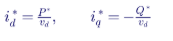
where vd is the PLL-aligned voltage magnitude. The PLL uses the q-axis voltage as its error signal:
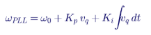
GFL control is mature, well understood and dominant in today's fleet. Its fundamental limitation is that it needs a voltage to follow. In an island with no other voltage source, it has no reference, and its controls cannot by themselves establish voltage or frequency.
2.2 Grid-forming control
A grid-forming inverter behaves as a controlled voltage source behind an impedance. It creates its own internal voltage magnitude E and angle θ, and the network determines the current that flows. The simplest and most widely used scheme is droop control:
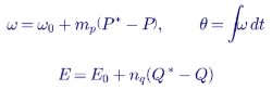
where mp and nq are the frequency and voltage droop coefficients and P and Q are filtered measurements. Other GFM schemes include virtual synchronous machines (which add an inertia term), power synchronization control, matching control and dispatchable virtual oscillator control. All share the defining property: the inverter holds an internal voltage phasor that does not depend on measuring an external one.
2.3 Power transfer from a voltage source
The active and reactive power a GFM inverter delivers through its coupling reactance X (filter plus transformer) are approximately:

where δ is the angle between the internal voltage E and the bus voltage V. The power is very sensitive to δ: with X = 0.15 pu, a 1° change in angle changes power by about 0.12 pu. That sensitivity is what makes GFM control respond instantly to load changes — and what makes angle errors at initialization or transfer so damaging.
2.4 Comparison
| Characteristic | Grid-following | Grid-forming |
|---|---|---|
| Behaves as | Current source | Voltage source behind impedance |
| Synchronization | PLL tracks external voltage | Internal angle from power balance (droop, virtual inertia) |
| Can energize or hold an island alone | No | Yes |
| Response to load step | After measurement and control delay | Instantaneous, through network physics |
| Weak-grid performance | Degrades at low short-circuit ratio | Generally strong at low short-circuit ratio |
| Current during faults | Directly controlled | Must be limited by control action; transient overcurrent risk |
| Fault current magnitude | Typically 1.0 to 1.2 pu | Typically 1.0 to 1.5 pu, sub-cycle peaks possible |
| Maturity | Mature, widely deployed | Rapidly maturing; requirements emerging |
3. Initialization: eliminating artificial transients
3.1 Why initialization matters
An EMT simulation starts from an initial state of every inductor current, capacitor voltage, machine flux and controller state. If those states are not mutually consistent, the simulation spends its first cycles moving from the inconsistent starting point to a consistent one. That movement looks exactly like a physical transient: current spikes, voltage oscillations, frequency swings and, sometimes, protection or current-limit operation that changes the rest of the run.
Consistent initialization means:
- a load flow solution at 60 Hz establishes bus voltages, angles and branch flows;
- every network element is initialized to that phasor solution;
- every controller is initialized so that its outputs reproduce the load flow injections, its integrators hold the values needed for zero error, and its filters hold their steady-state outputs;
- the simulation starts with all derivatives near zero.
3.2 Initializing a grid-forming controller
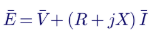
For a GFM inverter connected through coupling impedance R + jX and delivering current I to a bus at voltage V from the load flow, the required internal voltage is:
The controller states are then set as follows:
| State | Initial value |
|---|---|
| Internal angle δ | Angle of E |
| Voltage set point E0 | Magnitude of E, with Q* equal to the load flow reactive output |
| Frequency ω | 1.0 pu |
| Active power filter | Load flow P |
| Reactive power filter | Load flow Q |
| Power set point P* | Load flow P |
| Virtual inertia state (if used) | Zero acceleration |
| Inner voltage and current loop integrators | Values that produce E with zero error |
3.3 Worked example: Keentel's 13.8 kV microgrid
Base quantities on 45 MVA and 13.8 kV:

| Quantity | Load flow result |
|---|---|
| Utility source voltage | 1.04 pu |
| Bus voltage V | 0.998 pu at −3.9° |
| BESS output | 0.25 pu (11.25 MW), 0 Mvar |
| Utility supply | 0.42 pu (18.8 MW) and 0.21 pu (9.3 Mvar) |
| Coupling impedance | 0.005 + j0.15 pu |
| Required internal voltage E | 1.000 pu at −1.7° |
| Internal-to-bus angle δ | 2.2° |
With these states, the simulation starts in steady state: the inverter current stays at 0.25 pu from t = 0.
3.4 What a mismatch does
If the controller's internal angle is set 10° away from the correct value, the initial current error is approximately the voltage difference across the coupling reactance:

Combined with the 0.25 pu operating current, Keentel's simulation shows a peak of 1.23 pu. The sensitivity is nearly linear:
| Angle mismatch | Peak inverter current | Peak active power |
|---|---|---|
| 0° | 0.25 pu | 0.25 pu |
| 5° | 0.74 pu | 0.74 pu |
| 10° | 1.23 pu | 1.23 pu |
| 20° | 2.20 pu | 2.21 pu |
| 30° | 3.16 pu | 3.15 pu |
A real inverter's current limiter would clip these peaks, but clipping changes the controller's behavior and can trigger mode changes or protection that would not occur with correct initialization. A study that reports "current limiting during the first 100 ms" may be reporting nothing more than an initialization error.
3.5 Flat start and other initialization practices
A flat start — every state at zero and the sources ramped from zero — avoids inconsistent initial values by energizing the model gradually. It is robust but slow, and it does not represent the intended operating point until the model settles. In Keentel's flat-start case, the system reached the correct operating point after about 150 ms with a 1.22 pu voltage overshoot on the way. Flat start is acceptable when the simulation runs long enough to settle before any event, and when nothing in the model (such as protection or a current-limit latch) is triggered during settling.
| Practice | When to use it | Pitfalls |
|---|---|---|
| Load flow initialization of all states | Standard practice for transition and fault studies | Controller initialization must match vendor control code; generic routines may not |
| Flat start with source ramp | Models without reliable initialization routines | Long settling period and limiters may operate during settling |
| Initialize, then run a settling period before events | Recommended for all studies | Must confirm all states reach steady state before the event |
| Snapshot from previous run | Repeated studies on the same model | Snapshot must be regenerated whenever the model changes |
3.6 Signs of an initialization problem
- Current, power or frequency excursions in the first few cycles with no event applied.
- Results that change when the event time is moved later.
- Current limiters or protection elements operating before any event.
- DC offsets in phase currents that decay with the network X/R time constant.
- Different results from different simulation time steps.
Keentel's practice is to run every model for a settling period with no events, confirm flat traces for all monitored quantities, and only then apply disturbances.
4. Control transitions: more than a software toggle
4.1 Why transitions occur
Many BESS installations operate in GFL mode when grid-connected — for historical reasons, because interconnection requirements were written for current-source behavior, or because the vendor's GFM mode is intended only for islanded operation — and switch to GFM when an island is detected. The transition can be:
| Transition type | Trigger | Time available |
|---|---|---|
| Planned islanding | Operator or microgrid controller command | Seconds: power at the point of interconnection can be reduced to near zero first |
| Unplanned islanding | Utility outage, upstream fault or breaker trip | Milliseconds: detection must occur after the event |
| Reconnection (GFM → GFL or synchronized GFM) | Utility restored and synchronization achieved | Seconds: controlled synchronization |
| Black start | No source available | Seconds: GFM energizes the system |
4.2 What must be handed over
At the moment of transition, the GFM controller must start from the conditions the GFL controller and the network have created:
| GFM state | Bumpless value at transfer | Consequence if reset |
|---|---|---|
| Internal angle δ | Angle of V + Z·I from the PLL-measured voltage and actual current | Sudden angle step; current spike and voltage notch |
| Voltage set point | Magnitude of V + Z·I, then ramped to nominal | Voltage step; current spike |
| Frequency | PLL frequency (if credible) or nominal | Frequency step |
| Power filters | Measured P and Q | False power error drives frequency and voltage away |
| Inner loop integrators | Values producing the present output | Integrator windup or kick |
| Current limiter state | Present current | Limiter misoperation |
In Keentel's transition cases:
| Transition method (3-cycle detection) | Peak current after transfer | Voltage at transfer | Voltage overshoot | Time below 0.9 pu after transfer |
|---|---|---|---|---|
| States reset (angle 0, filters zero) | 0.97 pu | Notch to 0.13 pu | 1.13 pu | Under 1 ms, but with a severe notch |
| Angle and power states aligned; voltage restored in one step | 0.77 pu | No notch | 1.005 pu | Under 1 ms |
| Angle and power states aligned; voltage ramped over 20 ms | 0.70 pu | No notch | None | 17 ms |
| Angle and power states aligned; voltage ramped over 100 ms | 0.69 pu | No notch | None | 83 ms |
The choice of voltage ramp is a design trade-off: a faster ramp restores voltage sooner but draws more current to recharge network capacitance and re-magnetize loads. The best setting depends on the load's tolerance, the inverter's current margin and the presence of motors and transformers that will draw inrush current when voltage recovers.
4.3 Islanding detection delay
During the detection interval, the grid-following inverter cannot support the island. In the Keentel model, voltage falls to about 0.53 to 0.60 pu during that interval:
| Detection and transfer time | Total time below 0.9 pu (bumpless transfer, 20 ms ramp) |
|---|---|
| 1 cycle (17 ms) | 33 ms |
| 3 cycles (50 ms) | 67 ms |
| 6 cycles (100 ms) | 117 ms |
| 10 cycles (167 ms) | 183 ms |
| GFM before islanding (no transfer) | 0.7 ms |
Islanding detection methods include breaker status from the point of interconnection (direct transfer trip or hardwired status), passive methods (voltage, frequency, rate of change of frequency, phase jump), active methods (impedance measurement, frequency shift) and communication-based schemes. Breaker-status signals are fastest and most reliable when the utility breaker is local; passive and active methods are slower and subject to non-detection zones when load and generation are balanced.
4.4 Critical-load tolerance
The ITIC (CBEMA) curve describes the voltage tolerance of typical information technology equipment:
| Voltage | ITIC tolerance duration |
|---|---|
| 0% (interruption) | Up to 20 ms |
| 70% | Up to 0.5 s |
| 80% | Up to 10 s |
| 90% and above | Steady state |
In Keentel's model, the bus voltage during a 3-cycle detection interval is about 0.53 to 0.6 pu for about 50 ms. That falls outside the ITIC curve: equipment that just meets the curve may drop out. Only the grid-forming-before-islanding case keeps the critical load within the curve. Real data center loads behind UPS systems ride through such events on the UPS, but many process loads, variable frequency drives, control power supplies and contactors do not have that protection, and semiconductor fabrication tools are typically specified to SEMI F47, which allows 50% voltage for only 200 ms.
5. Seamless transfer: architectures that protect the critical load
5.1 Option 1: Grid-forming at all times
The BESS operates as a GFM voltage source while grid-connected, sharing load with the utility according to its droop and dispatch set points, and continues unchanged when the utility is lost. No transfer occurs, so there is no detection delay and no state handover. Keentel's simulation shows a voltage dip of less than one millisecond and a smooth transition to islanded frequency.
| Advantages | Considerations |
|---|---|
| No transition; inherently seamless | Interconnection requirements must accept GFM behavior while grid-connected |
| Inherent fast frequency and voltage response | Anti-islanding requirements of IEEE 1547 must be addressed through intentional island provisions |
| Strong performance on weak utility connections | Grid-connected power sharing depends on droop and secondary control coordination |
| Simplest protection philosophy for the transition itself | Fault current behavior must be coordinated in both grid-connected and islanded modes |
5.2 Option 2: GFL while grid-connected, fast bumpless transfer
The BESS operates in GFL mode, and a fast islanding detection signal triggers a bumpless GFM transfer. This can approach seamless performance when detection is fast (breaker status within a cycle) and the handover is carefully engineered, but some voltage disturbance during detection is unavoidable.
5.3 Option 3: Planned islanding only, with UPS or static switch for unplanned events
The microgrid islands intentionally — for example, ahead of forecast storms — with the BESS reducing the point-of-interconnection power flow to near zero before the breaker opens. Unplanned events are handled by UPS systems at the load or by a static transfer switch. This approach is common where the load already has UPS protection.
5.4 Option 4: Static switch at the point of interconnection
A thyristor-based static switch can separate the microgrid from the utility within a quarter to half cycle, much faster than a mechanical breaker. Combined with GFM operation, it minimizes the disturbance seen by critical loads during utility-side faults.
5.5 Selection
| Method | Description | Behavior |
|---|---|---|
| Current reference saturation | Inner current loop with limited reference | Fast; converter temporarily becomes current-source-like and may lose synchronization |
| Virtual impedance | Increase the virtual output impedance as current rises | Retains voltage-source behavior; slower |
| Mode switching to GFL during limit | Switch to a current-controlled mode with PLL | Fast protection, but introduces another transition |
| Voltage reference reduction | Reduce internal voltage during overload | Simple; may slow recovery |
6. Inverter current limiting
6.1 Why GFM current limiting is difficult
A voltage source does not control its own current; the network does. During faults, motor starting, transformer energization or large load steps, a GFM inverter would deliver whatever current the network draws. Power semiconductors cannot tolerate overcurrent for more than milliseconds, so GFM inverters must limit current by control action, typically to 1.1 to 1.5 pu of rating. Methods include:
| Method | Description | Behavior |
|---|---|---|
| Current reference saturation | Inner current loop with limited reference | Fast; converter temporarily becomes current-source-like and may lose synchronization |
| Virtual impedance | Increase the virtual output impedance as current rises | Retains voltage-source behavior; slower |
| Mode switching to GFL during limit | Switch to a current-controlled mode with PLL | Fast protection, but introduces another transition |
| Voltage reference reduction | Reduce internal voltage during overload | Simple; may slow recovery |
During current limiting, the GFM inverter is no longer an ideal voltage source, and its synchronization mechanism (droop or virtual inertia) may not see the true power imbalance. After the limit releases, the controller must recover synchronism without a second transient. These behaviors are vendor-specific and must be represented with vendor EMT models.
6.2 Worked example: current margin at islanding
In Keentel's microgrid, the BESS supplies 0.25 pu before islanding. At islanding it must instantly supply the whole critical load:
| Quantity | Value |
|---|---|
| Critical load at nominal voltage | 30 MW + 10 Mvar = 31.6 MVA |
| On 45 MVA base | 0.70 pu |
| Simulated steady current after islanding | 0.68 pu (voltage settles at 0.96 pu) |
| Margin to 1.2 pu current limit | 0.52 pu |
If the BESS were rated 30 MVA instead, the same load would be 1.05 pu — inside the current limit only in steady state, with no margin for transformer inrush, motor reacceleration or load restoration. A practical design rule is to size the GFM capacity so that the largest credible island load, plus the largest single motor-starting or transformer-energization step, remains within the inverter's short-time current capability.
6.3 Motor and transformer inrush
Induction motors draw five to seven times rated current when starting or reaccelerating after a voltage dip. Transformers draw magnetizing inrush of up to eight to twelve times rated current for their first cycles when energized. When an island is formed or voltage recovers after a transition, many motors reaccelerate together and transformers may be re-energized. The GFM inverter's current limit is then the bottleneck. Staged load pickup, soft starters and VFDs on large motors, and pre-insertion or point-on-wave energization for transformers keep inrush within the inverter's capability.
7. Frequency and voltage control in the island
7.1 Droop frequency deviation
With droop control, islanded frequency settles below nominal when the BESS supplies more than its set point:

In Keentel's model, mp = 0.02 pu/pu (2% droop) and the BESS picks up about 0.37 pu of additional power, giving Δf ≈ 0.02 × 0.37 × 60 ≈ 0.44 Hz, consistent with the simulated 59.55 Hz. Secondary control in the microgrid controller then restores frequency to 60 Hz over seconds by adjusting P*.
7.2 Multiple sources
When the island includes several GFM inverters, generators or combined heat and power units, droop settings determine load sharing:
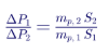
Mismatched droops cause one unit to take most of a load step and reach its current limit first. Generator governors and inverter droops have very different response speeds, so the inverter takes the initial step even if steady-state sharing is balanced. Coordinated settings and EMT verification are essential.
7.3 Voltage regulation
Reactive power droop shares reactive load among sources but allows voltage to fall with reactive demand. In Keentel's model, islanded voltage settles at 0.96 pu. A microgrid controller's secondary voltage control or a voltage set point schedule returns the critical bus to nominal.
7.4 Reconnection
Before reclosing to the utility, the microgrid must synchronize. IEEE 1547-2018 specifies synchronization limits for DER; for aggregate ratings above 1,500 kVA, frequency difference must be within 0.1 Hz, voltage difference within 3% and phase angle difference within 10°. The microgrid controller adjusts frequency and voltage set points to meet these limits, then closes the point-of-interconnection breaker with a synchronism-check relay (ANSI 25) supervising. After reconnection, the BESS either remains GFM or transitions back to GFL, and that transition also requires bumpless handling.
7.5 Worked example: sharing a load step with a generator
An islanded campus has the 45 MVA BESS (2% droop) and a 20 MW gas generator (5% governor droop). A 6 MW chiller plant restarts.
| Step | Calculation | Result |
|---|---|---|
| BESS droop on system base | 0.02 pu frequency per 45 MW | 0.0267 Hz per MW |
| Generator droop on system base | 0.05 pu frequency per 20 MW | 0.15 Hz per MW |
| Steady-state sharing ratio | (0.15) ÷ (0.0267) | BESS takes about 85% |
| BESS share | 0.85 × 6 MW | ≈ 5.1 MW |
| Generator share | 0.15 × 6 MW | ≈ 0.9 MW |
| Frequency change | 5.1 MW × 0.0267 Hz/MW | ≈ 0.14 Hz |
In the first cycles, the BESS takes essentially all 6 MW, because the generator's governor and engine respond over seconds. The steady-state split then settles to about 85/15. If the design intent is for the generator to carry sustained load and the BESS to provide only transient support, the microgrid controller's secondary control must shift the BESS set point back toward zero and raise the generator's set point — and the EMT and dynamic studies must confirm that the handover does not create slow oscillations between the two sources.
7.6 Black start with a grid-forming BESS
A grid-forming BESS can black-start a microgrid without diesel generators. The main technical challenge is energizing transformers and cables within the inverter's current limit.
| Approach | Description | Inrush outcome |
|---|---|---|
| Hard energization at full voltage | Close the transformer breaker with the BESS already at 1.0 pu | Inrush can reach many times transformer rating; inverter current limit is reached; voltage collapses |
| Soft energization (voltage ramp) | Close breakers with BESS at zero voltage, then ramp voltage over 0.5 to 2 seconds | Transformer flux builds gradually; inrush is minimal |
| Sequential energization | Energize the largest transformer first with a soft ramp, then pick up others at full voltage | Each subsequent inrush is supported by the already energized system |
| Point-on-wave closing | Close each phase at the instant that minimizes flux asymmetry | Reduces inrush where soft energization is not possible |
For example, a 13.8 kV campus with eight 3 MVA transformers totals 24 MVA of transformer capacity. If all were energized at full voltage, inrush of six to ten times rating could approach 150 to 240 MVA — far beyond the 45 MVA BESS's capability of about 54 MVA at 1.2 pu. A soft voltage ramp from zero reduces inrush to a small fraction of rated current, and the island then picks up load in stages. The microgrid controller sequence, breaker timing and the BESS's voltage ramp must be studied in EMT and verified during commissioning.
8. Protection coordination across operating modes
8.1 The fault current problem
Grid-connected, a 13.8 kV bus with 250 MVA of short-circuit capacity sees about:
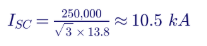
Islanded, the 45 MVA BESS with a 1.2 pu current limit can supply only:

That is less than a quarter of the grid-connected fault current and comparable to the load current of large feeders. Time-overcurrent relays set for grid-connected coordination may never operate in the island, or may operate too slowly.
8.2 Adaptive protection strategies
| Strategy | Description |
|---|---|
| Settings groups switched by breaker status | Relays use grid-connected settings when the point-of-interconnection breaker is closed and islanded settings when open |
| Differential protection (87B, 87L, 87T) | Independent of fault current magnitude; effective in both modes |
| Voltage-restrained or voltage-controlled overcurrent (51V) | Increases sensitivity when voltage is depressed by a fault |
| Negative-sequence and ground elements | Detect unbalanced faults at low current; inverter negative-sequence behavior must be known |
| Distance protection (21) | Used at higher voltages; inverter fault current behavior affects reach |
| Undervoltage-based fast tripping | Supplements overcurrent in the island |
| Communication-assisted schemes | Fast, selective tripping regardless of current magnitude |
8.3 Inverter fault response
Inverter fault current depends on control: some inverters inject balanced positive-sequence current only, others inject controlled negative-sequence current, and GFM inverters may produce sub-cycle peaks before current limiting acts. IEEE 2800-2022 now specifies negative-sequence current injection for transmission-connected IBRs, and similar expectations are emerging for distribution and microgrid applications. Protection studies must use vendor-specific EMT models to confirm relay operation for the inverter's actual fault response.
8.4 Grounding
A microgrid that is effectively grounded by the utility source may become ungrounded when islanded if the BESS step-up transformer is delta on the medium-voltage side. Ground faults in the island then produce little ground current and phase-to-ground overvoltage on unfaulted phases. Grounding transformers or wye-grounded transformer connections, with ground fault protection designed for the island, address this issue. NEC requirements for grounding of separately derived and interconnected systems apply.
9. Why EMT simulation matters
Positive-sequence RMS models are valuable for system-level studies of power flow, voltage regulation and frequency response, and modern grid-forming positive-sequence models extend their reach. Their assumptions — balanced fundamental-frequency phasors, simplified controls and network algebraic equations — limit their ability to capture:
- sub-cycle current peaks and current-limit behavior,
- PLL dynamics and loss of synchronism,
- controller state handover at transitions,
- unbalanced faults and negative-sequence behavior,
- transformer inrush and motor reacceleration,
- protection operation based on instantaneous quantities,
- interactions between inverters, filters and network resonances.
EMT simulation captures these directly, provided the network and control models have sufficient fidelity. Steady-state stability is only the beginning; the real test is what happens when operating modes change, control loops interact and current limits are reached.
9.1 Model fidelity requirements
| Element | Minimum fidelity for transition studies |
|---|---|
| BESS inverter | Vendor EMT model with actual control code, current limits, mode logic and protection |
| Step-up transformers | Saturation, winding connection, grounding |
| DC side | DC-link capacitance and battery model when DC dynamics affect limits |
| Loads | Composite: static, motor and power electronic loads with ride-through characteristics |
| Generators | Machine, exciter and governor models |
| Network | Cables, lines, capacitor banks and filters |
| Protection | Relays modeled with their actual elements and settings groups |
| Microgrid controller | Transition logic, timing and communication delays |
9.2 Average-value versus switching models
Average-value models (AVMs) replace switching devices with controlled voltage sources that reproduce the fundamental-frequency output. They are fast and suitable for most system-level transition studies. Detailed switching models are needed for harmonic studies, switching-frequency resonance and some protection studies. Keentel's results in this article use an average-value representation; project-specific studies use the vendor's validated model.
10. US standards and requirements
| Standard or requirement | Relevance to critical microgrids with GFM BESS |
|---|---|
| IEEE 1547-2018 and IEEE 1547.1-2020 | DER interconnection: ride-through, voltage and frequency response, anti-islanding, intentional islanding, synchronization |
| UL 1741 (including Supplement SB) | Inverter certification to IEEE 1547.1 test procedures |
| IEEE 2030.7 and IEEE 2030.8 | Microgrid controller functional specification and testing |
| IEEE 2030.9 | Microgrid planning and design |
| IEEE 2800-2022 | Performance requirements for transmission-connected IBRs, relevant for large campus interconnections at transmission voltage |
| NFPA 70 (NEC) Articles 700, 701, 702, 705, 706 and 710 | Emergency, legally required and optional standby systems; interconnected power production; energy storage systems; stand-alone systems |
| NFPA 855 | Installation of stationary energy storage systems |
| NFPA 99 and NFPA 110 | Health care facility essential electrical systems and emergency power performance |
| UL 9540 and UL 9540A | ESS safety and thermal runaway fire testing |
| ITIC (CBEMA) curve, SEMI F47 | Load voltage tolerance |
| NERC guidance on grid-forming IBRs | Functional expectations for grid-forming capability at the bulk system level |
Note that NFPA 99 and NFPA 110 impose specific requirements on emergency power for health care, including transfer times for life-safety branches; a BESS microgrid that supports those branches must satisfy them or be supplementary to compliant emergency generation.
11. A practical study and commissioning workflow
- Define critical loads and their tolerance: ITIC, SEMI F47, UPS ride-through, motor contactor dropout.
- Select architecture: GFM at all times, GFL with bumpless transfer, planned islanding, static switch.
- Build the model: vendor EMT models for inverters, detailed transformers, loads, generators, protection and microgrid controller logic.
- Initialize and verify: load flow initialization, settling period, flat traces before events.
- Study transitions: planned and unplanned islanding at minimum and maximum load, different import and export conditions, different detection times.
- Study disturbances in the island: faults, motor starting, transformer energization, load steps, loss of a generator.
- Study reconnection: synchronization and transfer back.
- Coordinate protection: settings groups, adaptive schemes, grounding.
- Commission and test: factory acceptance testing of controls, controller hardware-in-the-loop (CHIL) testing of the microgrid controller with the plant model, site acceptance tests including live islanding where permitted.
- Validate the model: compare field records with simulations; update models.
11.1 Controller hardware-in-the-loop testing
CHIL testing connects the actual microgrid controller — and sometimes actual inverter control boards — to a real-time simulation of the plant and network. It exposes timing, communication and logic errors that offline simulation cannot, and it allows unplanned islanding and fault cases to be tested safely before energization. IEEE 2030.8 provides a framework for microgrid controller testing that supports this approach.
12. Common misconceptions corrected
| Misconception | Engineering reality |
|---|---|
| "If the load flow converges, the microgrid works." | Load flow describes operating points, not the transition between them. |
| "Initial transients in a simulation are physical." | Inconsistent initialization creates artificial transients; a 10° error produced a 1.23 pu spike in Keentel's model. |
| "Switching from GFL to GFM is a software setting." | Controller states, references and filters must be handed over consistently, or the transition creates large transients. |
| "Islanding detection in a few cycles is fast enough." | For loads without UPS protection, voltage during the detection interval can violate ITIC limits. |
| "GFM inverters provide fault current like generators." | They are limited to about 1.1 to 1.5 pu; island fault current can be a quarter of grid-connected fault current or less. |
| "Positive-sequence models are enough." | They miss sub-cycle behavior, current limiting and transition logic. EMT is needed for these studies. |
| "A 45 MVA inverter can connect directly at 13.8 kV from a 2 kV DC bus." | Converter voltage limits require a step-up transformer; the transformer must be modeled. |
13. Key takeaways
- Initialize every state from a load flow, and verify a quiet settling period before applying events.
- Grid-following inverters cannot hold an island alone. A grid-forming source is required.
- Transitions must be bumpless: align angle, voltage, power filters and integrators with measured conditions.
- Detection time is load time at reduced voltage. Grid-forming before islanding avoids it.
- Size grid-forming capacity for current, not just power, including inrush and load pickup.
- Protection must work at a quarter of the fault current, using settings groups and current-independent schemes.
- Use EMT with vendor models for transitions and protection, and validate with CHIL and field testing.
14. How Keentel Engineering helps
Keentel Engineering designs and studies microgrids, BESS interconnections and critical power systems for
data centers, hospitals, water utilities, campuses and industrial facilities, from 480 V to 765 kV.
| Stage | Keentel scope | Outcome |
|---|---|---|
| Architecture and feasibility | Critical-load analysis, GFM/GFL strategy, static switch evaluation, BESS sizing for current and energy | The right architecture for the load's tolerance |
| Steady-state studies | Load flow, short-circuit, arc flash and voltage drop in grid-connected and islanded modes | Solid operating points in every mode |
| EMT transition studies | Initialization, planned and unplanned islanding, reconnection, black start, current limiting | Verified seamless transfer |
| Protection design | Adaptive settings groups, differential and communication-assisted schemes, island grounding | Protection that works in every mode |
| Interconnection | IEEE 1547 and utility requirements, intentional island provisions, IEEE 2800 for transmission-level campuses | Faster utility approval |
| Controller testing | CHIL test plans and witness testing, commissioning support | Logic and timing proven before energization |
| Code compliance | NEC 700/701/702/705/706, NFPA 855, NFPA 99/110 coordination | Compliant, permit-ready design |
Why clients choose Keentel Engineering
- Control-aware engineering: we understand inverter controls as well as the network.
- EMT depth: detailed modeling of BESS, transformers, loads and protection.
- Critical facility experience: data center, hospital and water utility power architectures.
- Practical design: from studies to stamped drawings and commissioning support.
- Licensed professional engineering: a Florida-registered firm with offices in Tampa, Austin, Sacramento and Baltimore, supporting projects nationwide.
Planning a microgrid or grid-forming BESS for a critical facility? Talk to Keentel Engineering at (813) 389-7871, contact@keentelengineering.com, or book a 15-minute scoping call at calendly.com/keentel-engineering/15min.
Part C — Case Studies
The following are illustrative scenarios based on conditions typical of US critical microgrids. They show how Keentel Engineering approaches grid-forming BESS initialization and transition problems; site details are generalized and figures are rounded.
Case Study 1 — Hospital campus microgrid: equipment drops during transfer
Situation. A hospital campus with a 13.8 kV loop, a 20 MW BESS, combined heat and power and diesel generators commissions a microgrid. During the first planned islanding test, the transfer itself goes well, but during a later unplanned utility outage, imaging equipment, several air handlers and a sterilization process drop offline, even though the microgrid successfully forms an island.
Analysis. Keentel reviews event records and builds an EMT model with the vendor's inverter model and the microgrid controller's logic. The BESS operates in GFL mode when grid-connected and transfers to GFM after a passive islanding detection with a delay of about 8 cycles. During that interval, bus voltage sits near 0.6 pu, outside ITIC limits and below the dropout voltage of motor contactors. The transfer also resets the GFM power filters, causing a brief frequency excursion.
Engineered solution. Keentel recommends operating the BESS in GFM mode while grid-connected, with the utility's agreement under the site's intentional-island provisions, plus a hardwired breaker-status signal for the microgrid controller. Protection settings groups are revised for both modes. Life-safety branches remain on generator-backed automatic transfer switches compliant with NFPA 99 and NFPA 110.
Outcome. A subsequent unplanned outage passes with no equipment dropout, and the microgrid controller's logs show a voltage dip lasting less than one cycle.
Case Study 2 — AI data center campus: BESS bridging generator start
Situation. An AI data center campus at 34.5 kV with 13.8 kV distribution uses a large BESS to carry the campus during utility events while gas generators start. The design team's RMS study shows comfortable margins, but an EMT review is required by the owner before final design.
Analysis. Keentel's EMT study shows that the BESS's GFM current limit is reached during islanding because chiller motors reaccelerate and several 13.8 kV transformers re-magnetize together after the voltage dip from upstream utility faults. During current limiting, the inverters' synchronization behavior changes, and in some cases a second disturbance follows release of the limit. Island fault current is about one-fifth of grid-connected fault current, and several feeder relays would not operate in the island.
Engineered solution. Keentel recommends additional GFM capacity sized for reacceleration current, staged chiller restart through the building management system, adaptive relay settings groups, and bus differential protection on the main 13.8 kV switchgear. The inverter vendor provides a revised current-limiting setting validated in the EMT model.
Outcome. The revised design keeps inverter current within limits in all studied cases, relays operate correctly in both modes, and the owner proceeds with confidence in the campus's ride-through capability.
Case Study 3 — Water utility microgrid: when the model, not the plant, was unstable
Situation. A water utility's treatment plant microgrid study reports large current oscillations and repeated inverter current limiting immediately after every simulated islanding event, leading the design team to propose an expensive increase in BESS capacity.
Analysis. Keentel reviews the model and finds that the GFM controller was initialized with default angle and power filter states rather than from the load flow, and that the islanding event was applied only 50 ms after the simulation started, before the initialization transient had settled. The apparent instability was an initialization artifact superimposed on the islanding event.
Engineered solution. Keentel re-initializes the model from a consistent load flow, adds a two-second settling period before events, implements the vendor's actual transfer logic with state alignment, and repeats the study across load and import conditions.
Outcome. With consistent initialization, the islanding cases show peak currents well within the inverter's limits. The utility avoids the proposed capacity increase, and the corrected model becomes the basis for the controller hardware-in-the-loop test plan.
Part D — Technical FAQ: Grid-Forming BESS and Microgrid Transitions
A grid-following inverter is a current source that synchronizes to an external voltage with a PLL. A grid-forming inverter is a voltage source that creates its own voltage and frequency reference, so it can energize and hold an island.
It needs a voltage to follow. Once the utility is gone, there is no independent reference, and its PLL and current controls cannot by themselves establish stable voltage and frequency.
Every network and controller state is set from a load flow solution so that the simulation begins in steady state, with no artificial transients at t = 0.
In Keentel's model, a 10° angle mismatch produced a 1.23 pu current peak at an operating point of 0.25 pu. The error scales roughly as 2E·sin(Δθ/2) ÷ X.
Run the model with no events. If quantities move during the first cycles, or results change when event timing is shifted, the initialization is inconsistent.
A transition in which the incoming controller's states — angle, voltage, power filters, integrators — are set to match the present measured conditions, so its output is continuous with the outgoing controller's.
The output steps abruptly. In Keentel's model, resetting states caused a voltage notch to 0.13 pu and a current swing to 0.97 pu.
Ramping limits the current needed to restore voltage, recharge capacitance and re-magnetize loads. The ramp time trades recovery speed against current.
During detection, a grid-following inverter cannot support voltage. Each cycle of delay is a cycle of reduced voltage at the critical load, which can violate ITIC or SEMI F47 tolerance.
Yes. Many modern inverters support grid-connected GFM operation, which avoids transitions entirely. Utility interconnection requirements and IEEE 1547 provisions must be addressed.
Through control action: current reference saturation, virtual impedance, voltage reduction or temporary mode switching, typically limiting current to 1.1 to 1.5 pu.
While limited, the inverter is no longer an ideal voltage source, and its synchronization mechanism may not see the true power imbalance. Recovery from the limit must not create a second transient.
For current, not only power and energy: the largest island load plus the largest motor reacceleration or transformer inrush step must remain within the inverter's short-time current capability.
With droop control, frequency falls in proportion to the extra power the BESS supplies. Secondary control in the microgrid controller restores 60 Hz over seconds.
For aggregate DER ratings above 1,500 kVA, frequency difference within 0.1 Hz, voltage difference within 3% and phase angle difference within 10°.
Inverter-limited fault current may be a quarter or less of grid-connected fault current, so overcurrent relays set for grid-connected operation may not operate.
Differential protection, communication-assisted schemes, voltage-restrained overcurrent, negative-sequence elements and adaptive settings groups switched by breaker status.
For system-level power flow, voltage regulation and frequency response. EMT is required for sub-cycle transitions, current limiting, unbalanced faults and protection behavior.
Testing the actual microgrid controller, and sometimes inverter control hardware, against a real-time simulation of the plant to verify logic, timing and performance before energization.
IEEE 1547 and 1547.1, UL 1741, IEEE 2030.7, 2030.8 and 2030.9, IEEE 2800 for transmission-level connections, NEC Articles 700 to 710, NFPA 855, NFPA 99 and 110, and UL 9540 and 9540A.
References and Further Reading
Links were current at publication (October 2026).
- IEEE Std 1547-2018 and IEEE Std 1547.1-2020, Interconnection and Interoperability of Distributed Energy Resources and Conformance Test Procedures. IEEE.
- IEEE Std 2030.7-2017, Specification of Microgrid Controllers; IEEE Std 2030.8-2018, Testing of Microgrid Controllers; IEEE Std 2030.9-2019, Planning and Design of Microgrids. IEEE.
- IEEE Std 2800-2022, Interconnection and Interoperability of Inverter-Based Resources with Transmission Systems. IEEE.
- NFPA 70, National Electrical Code; NFPA 855, Installation of Stationary Energy Storage Systems; NFPA 99, Health Care Facilities Code; NFPA 110, Emergency and Standby Power Systems. National Fire Protection Association.
- UL 1741, UL 9540 and UL 9540A. UL Standards & Engagement.
- NERC, Grid Forming Technology: Bulk Power System Reliability Considerations, and related NERC guidance on grid-forming functional specifications. North American Electric Reliability Corporation.
- ITI (CBEMA) Curve Application Note. Information Technology Industry Council.
- SEMI F47, Specification for Semiconductor Processing Equipment Voltage Sag Immunity. SEMI.
- R. H. Lasseter et al., "Grid-Forming Inverters: A Critical Asset for the Power Grid," IEEE Journal of Emerging and Selected Topics in Power Electronics, 2020.
- Y. Lin et al., Research Roadmap on Grid-Forming Inverters, NREL Technical Report, 2020.
- UNIFI Consortium, Specifications for Grid-Forming Inverter-Based Resources.
Disclaimer
This article is general technical information for educational purposes. It is not engineering advice for any specific project and does not create a professional relationship. Simulation results come from Keentel Engineering's simplified average-value models with illustrative parameters; actual behavior depends on vendor-specific inverter controls, current limits, transformers, loads, protection and microgrid controller logic, and must be verified with validated vendor models, controller testing and field commissioning. Designs must follow current IEEE standards, the NEC, NFPA codes, utility interconnection requirements and project-specific engineering analysis, sealed by a licensed professional engineer where required.
Case studies are illustrative scenarios based on typical project conditions, not records of specific client projects. Figures are rounded and indicative.
IEEE, NERC, NFPA, UL, ITI, SEMI and other names are the property of their respective owners. Keentel Engineering is not affiliated with or endorsed by these organizations or any software or equipment vendor.
| Office | Address | Phone |
|---|---|---|
| Head Office — Tampa | 400 N Ashley Dr STE #2600, Tampa FL 33602 | (813) 389-7871 |
| Austin | 5900 Balcones Drive STE 100, Austin TX 78731 | (512) 591-0752 |
| Sacramento | 1401 21st St Ste R, Sacramento CA 95811 | (916) 913-4524 |
| Baltimore | 306 W Redwood St STE 200, Baltimore MD 21201 | (410) 225-2181 |

About the Author:
Sandip "Sonny" R. Patel, P.E.
IEEE Senior Member · Founder & CEO, Keentel Engineering
In 1995, Sonny Patel earned his Electrical Engineering degree from the University of Illinois. But degrees don't build legacies — action does.
For three decades, he has worked the power industry from every side of the table: 16 years as a utility engineer at Exelon/Commonwealth Edison; generation leadership across hydroelectric, industrial steam turbine, and a 9 GW renewable fleet; NERC Regional Entity Senior Compliance Engineer and Audit Team Lead, auditing some of the nation's largest utilities; and testing and commissioning lead on equipment up to 765 kV — the very top of the North American grid.Utility. Generator. Regulator. Consultant. Few engineers have seen all four seats. Fewer still have sat in them.
His experience spans nuclear, hydro, conventional generation, renewables, oil and gas, mining — and today's data centers, where he is authoring a three-book series on data center design. He is a Licensed Professional Engineer in six states and a Licensed Electrical Contractor in Florida (Unlimited EC) — he doesn't just design the work; he's qualified to stand behind its execution.Today, as Founder and CEO of Keentel Engineering, Sonny leads a nationwide team of engineers delivering substation design, power system studies, NERC compliance, and commissioning — done right, coast to coast.Three decades. Every side of the table. One standard: accountable engineering.
Services

Let's Discuss Your Project
Let's book a call to discuss your electrical engineering project that we can help you with.
About the Author:
Sandip "Sonny" R. Patel, P.E.
IEEE Senior Member · Founder & CEO, Keentel Engineering
In 1995, Sonny Patel earned his Electrical Engineering degree from the University of Illinois. But degrees don't build legacies — action does.
For three decades, he has worked the power industry from every side of the table: 16 years as a utility engineer at Exelon/Commonwealth Edison; generation leadership across hydroelectric, industrial steam turbine, and a 9 GW renewable fleet; NERC Regional Entity Senior Compliance Engineer and Audit Team Lead, auditing some of the nation's largest utilities; and testing and commissioning lead on equipment up to 765 kV — the very top of the North American grid.
Utility. Generator. Regulator. Consultant. Few engineers have seen all four seats. Fewer still have sat in them.
His experience spans nuclear, hydro, conventional generation, renewables, oil and gas, mining — and today's data centers, where he is authoring a three-book series on data center design. He is a Licensed Professional Engineer in six states and a Licensed Electrical Contractor in Florida (Unlimited EC) — he doesn't just design the work; he's qualified to stand behind its execution.
Today, as Founder and CEO of Keentel Engineering, Sonny leads a nationwide team of engineers delivering substation design, power system studies, NERC compliance, and commissioning — done right, coast to coast.Three decades. Every side of the table. One standard: accountable engineering.
Leave a Comment
Thank you for contacting us.
We will get back to you as soon as possible.
We will get back to you as soon as possible.
Oops, there was an error sending your message.
Please try again later.
Please try again later.
Related Posts
By SANDIP R PATEL
•
October 23, 2026
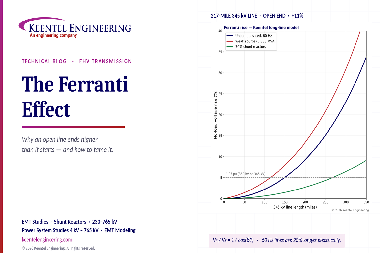
Explore the Ferranti effect in EHV transmission lines: voltage rise, 345 kV examples, switching overvoltages, shunt reactor sizing and mitigation.
By SANDIP R PATEL
•
October 21, 2026
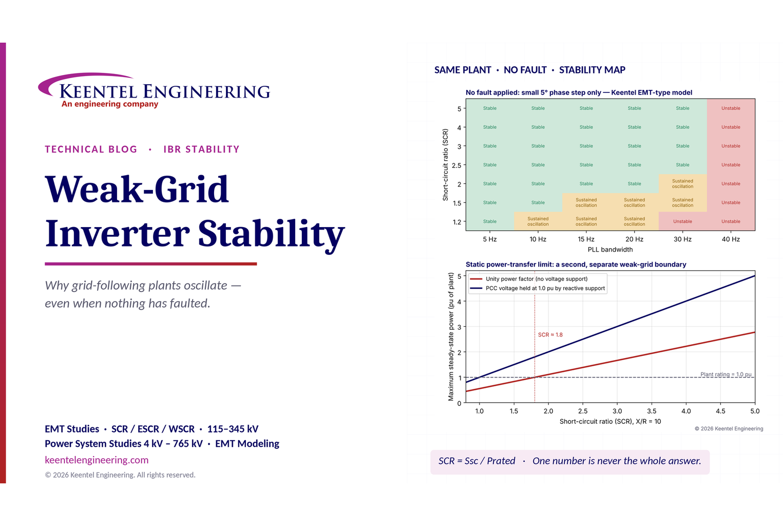
Learn why grid-following inverters become unstable without grid faults. Explore SCR, PLL interactions, EMT studies, grid strength, and mitigation.
By SANDIP R PATEL
•
October 21, 2026
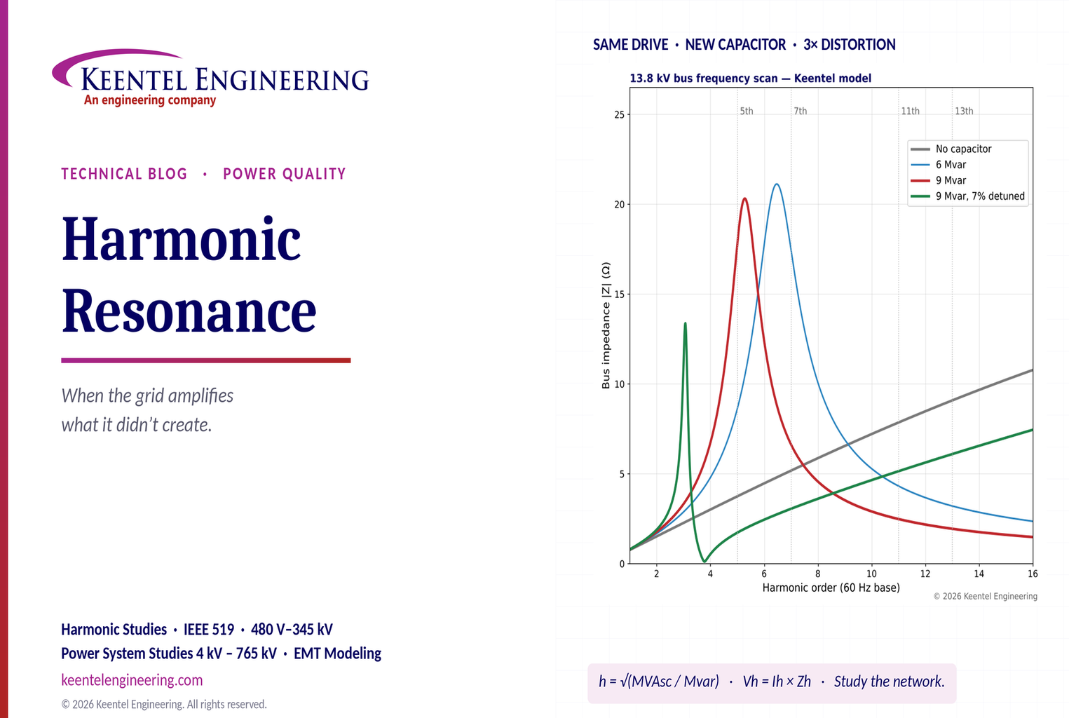
Learn how harmonic resonance amplifies distortion in power systems. Explore capacitor banks, detuned reactors, frequency scans, and IEEE 519 solutions.
By SANDIP R PATEL
•
October 20, 2026
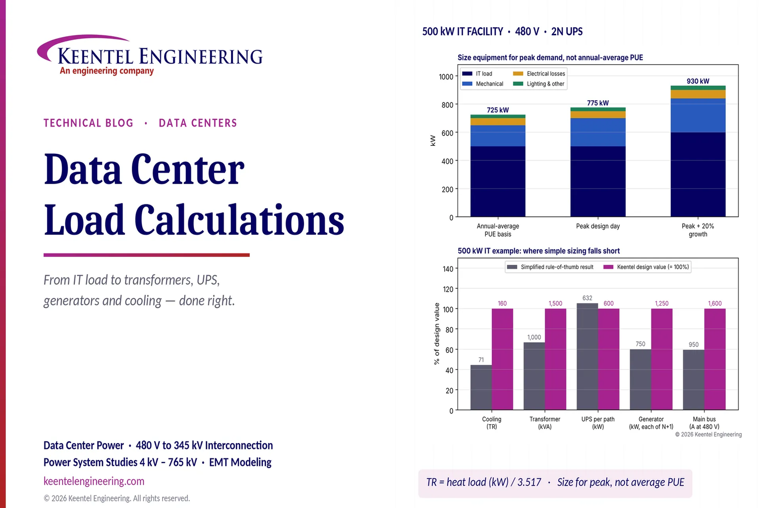
Learn data center electrical load calculations, including IT demand, PUE, UPS and generator sizing, cooling loads, redundancy, and worked US examples.
By SANDIP R PATEL
•
October 20, 2026
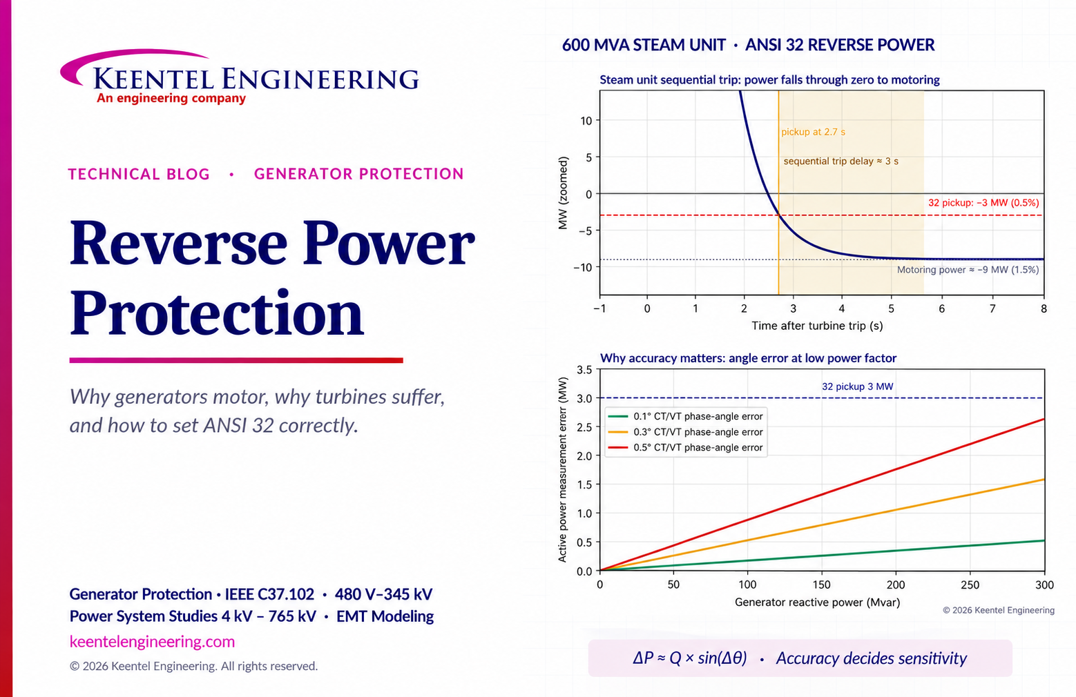
Learn reverse power protection (ANSI 32), generator motoring, relay pickup settings, time delays, sequential tripping and testing for US power plants.
Copy

By Team 2 Dexora
•
October 20, 2026
Explore grounding system testing with Keentel Engineering. Learn IEEE 80/81 methods, soil resistivity, ground resistance, and touch and step voltage safety.

By SANDIP R PATEL
•
October 13, 2026
Plan data center capacity with land screening, MW-per-acre estimates, grid power availability and interconnection feasibility studies from Keentel Engineering.
By SANDIP R PATEL
•
October 11, 2026
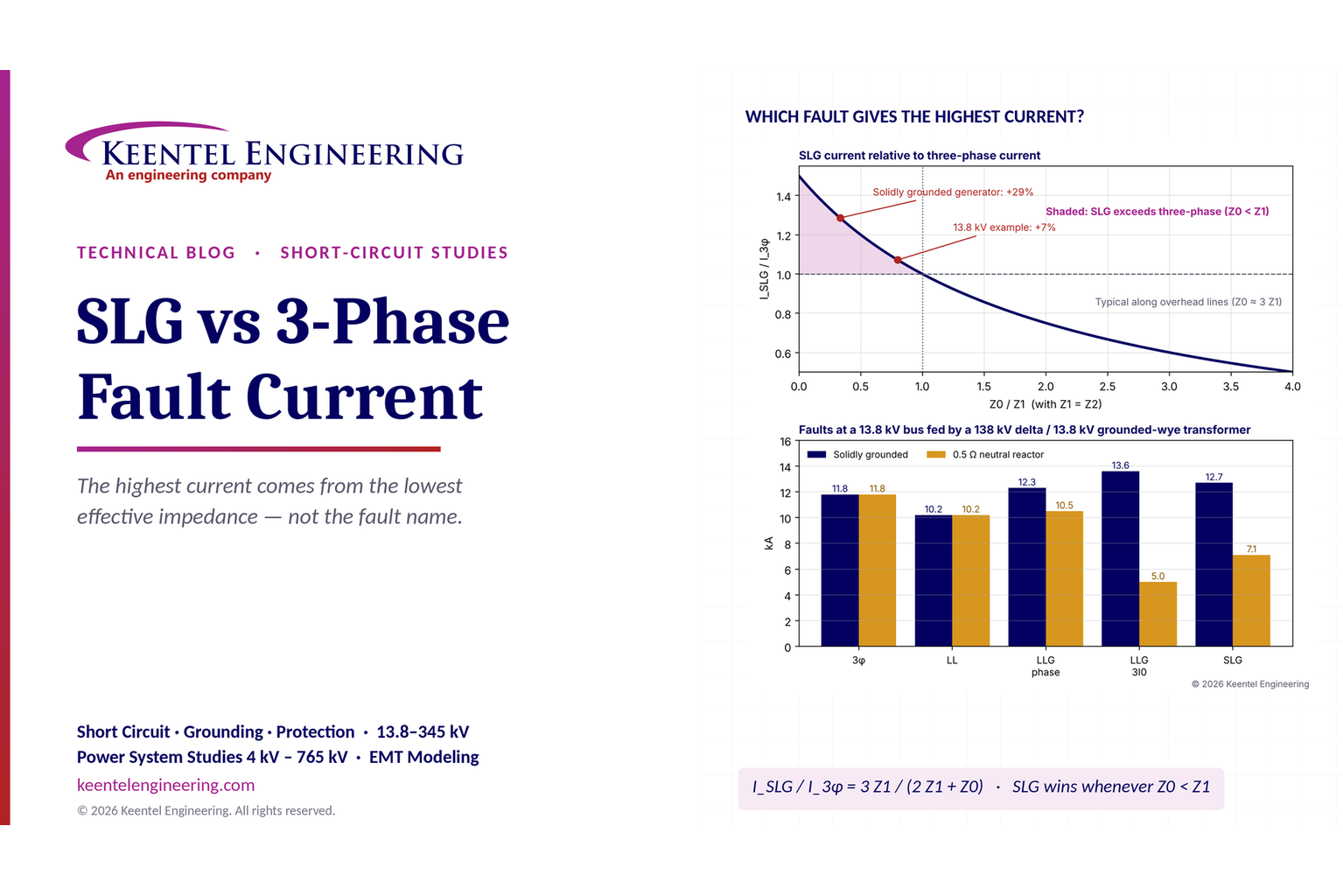
Learn which fault produces the highest current at a bus, why SLG faults can exceed three-phase faults, and how symmetrical components determine fault duty.
By SANDIP R PATEL
•
October 11, 2026
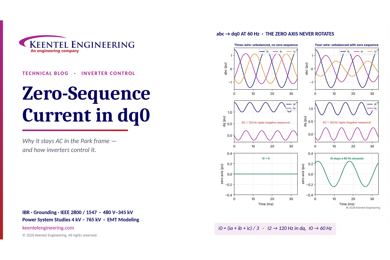
Learn why zero-sequence current pulsates in the dq0 frame, how Park's transformation works, and how inverter controls handle unbalance and ground faults.