
A Coordinated Electric System Interconnection Review—the utility’s deep-dive on technical and cost impacts of your project.
Challenge: Frequent false tripping using conventional electromechanical relays
Solution: SEL-487E integration with multi-terminal differential protection and dynamic inrush restraint
Result: 90% reduction in false trips, saving over $250,000 in downtime
ERCOT enforces all of the above through simulation, which means your model is your compliance case. The bar is now high:
- Whole-facility scope. The model must represent everything the IT load, the UPS and power conversion, the cooling plant, the protection and control systems in formats compatible with ERCOT's study platforms (PSS/E, PSCAD, TSAT).
- Real control loops, not approximations. Generic textbook representations are unacceptable. The model must capture the actual inner control behavior of your power electronics.
- Hardware-validated converter models. For electronic loads, the PSCAD model must be benchmarked against actual hardware testing including voltage ride-through and subsynchronous response. A model assembled from standard PSCAD library blocks fails by definition, because a generic block has never been tested against your vendor's hardware. The good news: validation is a hardware-type test, so results for a given converter product are reusable across every facility that uses it.
- Format migration. Facilities that previously submitted the older composite load model (CMLD) format must transition to EPRI's PERC1 format.
- Three checkpoints. Models are reviewed before the stability study begins (no model, no study), before each quarterly stability assessment, and for electronic loads one final time before energization, when you must submit as-built models with a documented comparison against the previously studied data and a sworn attestation that the model matches actual field settings. ERCOT's review takes 10 business days, extendable by 20 put it on your critical path.
- A living obligation. Change your technology, controls, or relay settings in a way that affects ride-through including converting a crypto mining site to an AI data center — and you've triggered a new interconnection study, even if your megawatts don't change.
| Parameter | Detail |
|---|---|
| System | 230 kV / 138 kV transmission corridors, wind and wet-snow icing exposure |
| Data basis | 15 years of minute-resolution forced-outage records + regional weather observations |
| Core methods | Event grouping, MVA performance curves, time-to-95%-restore, area outage rate curves, fragility modeling, rerun-history benefits, exceedance and log-domain risk metrics |
| Headline result | ≈85% of maximum resilience benefit at 60% of original capital; worst-event restoration window cut from 11 days to 5 in rerun-history terms |
| Decision supported | Capital portfolio selection; resilience plan filing; post-investment verification framework |
| System / Topic | Governing Standard(s) | What It Controls |
|---|---|---|
| Overall plant electrical distribution | IEEE 141 (Red Book); IEEE 666 | Distribution architecture, voltage selection, design of generating station auxiliary service systems |
| Power system studies | IEEE 399 (Brown Book); IEEE 551 | Load flow, symmetrical/asymmetrical short circuit, motor starting methodologies down to the lowest LV panelboard |
| Protection & coordination | IEEE 242 (Buff Book); IEEE 3004.5; IEEE C37 series | Generator relaying (21, 59N, 87G), time-current coordination, selective clearing between LV and MV tiers |
| GSU / UAT / SST transformers | IEEE C57.12.00 and C57 family | Transformer ratings, impedance, testing, loading |
| HV switchyard breakers | IEEE C37.06 | AC high-voltage circuit breaker preferred ratings |
| MV switchgear (13.8 kV) | IEEE C37.20.2; IEEE C37.20.7 | Metal-clad construction, compartmentalization, vacuum breakers; arc-resistant design with plenum venting |
| MV cable | UL 1072; ICEA S-93-639 (NEMA WC 74) | Type MV-105 shielded cable, 133% insulation level for HRG systems |
| LV switchgear (480 V) | IEEE C37.13; UL 1558 | Metal-enclosed LV power circuit breaker switchgear to 635 V, draw-out ACBs with electronic trip units |
| Motor control centers | UL 845; NEMA ICS 18 | LV-MCC construction, MCCB/MCP protection for motors under ~200 HP |
| Motors | NEMA MG-1 | Motor performance, starting characteristics, service factors |
| DC & battery systems | IEEE 485; IEEE 946 | Lead-acid battery sizing (125/250 VDC), DC auxiliary system design |
| Grounding | IEEE 80; IEEE 142 (Green Book) | Ground grid step/touch potential limits; system grounding including high-resistance grounding |
| Lightning protection | IEEE 998 | Direct-stroke shielding of switchyard and outdoor generator structures |
| Arc flash & electrical safety | IEEE 1584; NFPA 70E | Incident energy calculation; worker safety boundaries and PPE |
| Fire protection | NFPA 850 | Fire protection and risk management for combustion turbine generating plants |
| Installation code | NEC (NFPA 70); NESC | Wiring methods inside the plant fence; overhead/outdoor clearances at the switchyard |
| Interconnection & compliance | FERC LGIP; NERC MOD-025/026/027, PRC-019/024/029, FAC-008 | Interconnection process, model validation, protection/ride-through coordination, facility ratings |
| IFC / Construction Deliverable | Purpose |
|---|---|
| Stamped IFC packages | Legal basis for construction; P.E. responsible charge |
| Final relay settings & TCCs | Protection as-installed matches the coordination study |
| Calculation archive | Owner records; NERC audit evidence trail |
| Commissioning procedures | Safe, sequenced energization; MOD field testing |
| Construction support | RFIs, field changes, FAT/SAT witness |
| As-builts & model handoff | Operating baseline; future study currency |
| Metric | Outcome |
|---|---|
| Defects found pre-occupancy | Three topology defects and one settings-mismatch family corrected before load migration; the shared-switchboard defect alone would have invalidated the concurrently-maintainable claim on day one |
| IST findings | Fourteen additional discrepancies surfaced under scenario testing (control logic, alarm mapping, one generator sequencing fault) — all closed before handover instead of during operations |
| Black-building test | Passed on second execution; the first attempt exposed the generator sequencing fault under true block load, exactly the failure the compressed plan would never have found |
| Handover quality | Operations team certified on the actual failure scenarios; corrected EOPs and settings documentation delivered as controlled documents |
| Business outcome | Occupancy proceeded three weeks behind the original date — against an independent estimate that the uncorrected sequencing fault carried a high probability of a full facility outage within the first year |
Part 2 — Frequently Asked Questions: Large Load Interconnection
An electric grid must remain in continuous balance — generation onto the grid must equal consumption from it at every instant. PJM achieves this balance, and prices it, through a layered market architecture. Each layer operates on a different time horizon, and each one touches project economics differently.
| Domain | Key Standards / Codes | What They Govern |
|---|---|---|
| Fire safety | NFPA 855; UL 9540 / UL 9540A | Installation requirements, separation, gas management; system safety listing and thermal-runaway fire testing |
| Grid interconnection | IEEE 1547 (distribution); IEEE 2800 (transmission IBRs) | Ride-through, reactive capability, power quality, and performance at the point of interconnection |
| Power quality | IEEE 519 | Harmonic distortion limits at the PCC |
| Protection & grounding | IEEE 80 / 81 / 142; C37 series | Grounding system design and testing; protective relaying |
| Reliability compliance | NERC standards (incl. PRC ride-through requirements) | Registered-entity obligations for grid-connected storage |
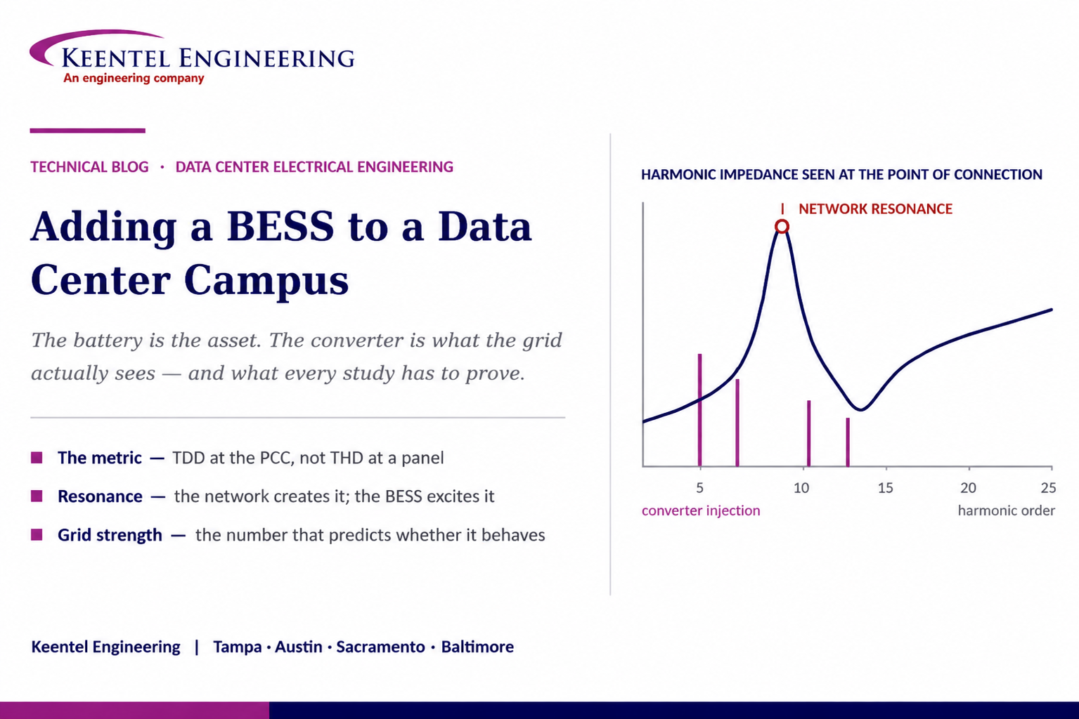
Adding a BESS to a Data Center Campus
Aug 28, 2026 | Blog
What Battery Storage Actually Does to Power Quality at the Point of Interconnection, Which Studies Have to Prove It, and Why the Inverter — Not the Battery — Decides the Outcome
1. Executive Summary
Battery energy storage has moved from the periphery of data center design to its centre. Storage is now being deployed on data center campuses to bridge outages, shave peaks, defer utility infrastructure, provide the load flexibility that increasingly determines how quickly a large load can be interconnected at all, and in some markets to participate in wholesale services. The commercial case is well understood. The electrical consequences are frequently not.
The framing that causes the most trouble is treating storage as a container of energy. A BESS is a power-electronic converter with a battery attached. Everything the grid experiences — harmonic current injection, reactive support, ramp behaviour, fault current contribution, ride-through, stability under weak-grid conditions — is determined by the power conversion system and its control tuning, not by the cells. The energy capacity sets how long it can do something. The inverter sets what it does.
On a data center campus the analysis is harder than on a standalone storage site, for one reason: the site is already an unusually distorted electrical environment before the BESS arrives. A large data center is a concentration of rectifier front ends — UPS systems, IT power supplies, variable-speed drives on the mechanical plant — sitting behind a long medium-voltage cable system with substantial distributed capacitance. Adding a converter of comparable rating to that environment is not a superposition problem that can be waved through; harmonic currents from different sources can cancel or reinforce depending on phase, and the network the BESS is injecting into may already have a parallel resonance sitting near a harmonic order the converter produces.
This paper works through what actually changes when a BESS is added at a data center campus: the correct harmonic compliance framework and why the metric is total demand distortion at the point of common coupling rather than voltage total harmonic distortion at a panel, how network resonance is created and excited, what governs voltage fluctuation and flicker, why grid strength and control interaction dominate the analysis on weak interconnections, what protection and overvoltage behaviour changes, and the complete study set an owner should expect. It closes with a mitigation toolkit, a compliance measurement protocol, and a twenty-question FAQ.
The sentence the source graphic gets right
The battery may be the asset, but the question that determines whether the project is buildable is how the grid — and the campus’s own power quality — respond once it is connected.
That question is answered by studies performed during design, using validated manufacturer models of the specific converter being purchased. It is not answered by a datasheet line stating that total harmonic distortion is below five percent.
2. Why Storage Is Appearing on Data Center Campuses
The design implications differ by use case, and the use case must be settled before the electrical design begins, because it determines the converter rating, the duty cycle, the point of connection, and the interconnection pathway.
- Bridging and ride-through. Lithium storage replacing or augmenting conventional UPS energy storage, extending autonomy and reducing the frequency of generator starts. Connection is typically at low voltage within the critical power path.
- Peak shaving and demand management. Reducing billing demand and deferring utility service upgrades. Connection is typically at the campus medium-voltage bus.
- Load flexibility as interconnection currency. This is the fastest-growing driver. Where utilities and system operators are constrained on large-load interconnection, the ability to curtail or shift campus demand on request — without dropping IT load — is increasingly what determines the energisation date. Storage is the mechanism that makes a firm IT load look flexible from the utility’s side of the meter.
- Generator reduction. Displacing some engine-generator capacity or runtime, with consequences for air permitting, fuel storage, and the resilience case that has to be demonstrated during commissioning.
- Wholesale market participation. Frequency response, regulation, or capacity, which brings the facility into a different regulatory and performance regime and imposes telemetry, model, and ride-through obligations.
Each of these places the BESS at a different point in the single line and subjects it to a different interconnection framework. Storage inside the critical power path at low voltage is a facility design problem. Storage on the medium-voltage campus bus operating in parallel with the utility is an interconnection problem, and the study obligations, model requirements, and protection requirements change accordingly.
3. The Inverter Is the Asset
The power conversion system determines grid behaviour through a small number of design and tuning choices, and the electrical engineer needs the manufacturer’s specifics on each of them before any study can be run.
- Switching frequency and modulation strategy, which set where converter-produced current distortion appears in the frequency spectrum. Modern converters push the dominant switching content into the kilohertz range, which is a different problem from the low-order harmonics produced by the six-pulse rectifiers that shaped the classic distortion literature.
- Output filter topology — typically an inductor-capacitor-inductor arrangement — whose capacitance is itself a network element that participates in resonance, and whose damping determines behaviour at the filter’s own resonant frequency.
- Current control bandwidth and the phase-locked loop tuning, which govern stability margin against network impedance and are the mechanism behind converter-network control interactions on weak systems.
- Reactive capability and the reactive priority setting, which determine what voltage support is available and whether the converter gives up real power to provide it.
- Ramp rate limits and their configurability, which govern the voltage fluctuation the site imposes on the network.
- Fault current contribution and duration, typically limited to a small multiple of rated current, which is the single most consequential difference between an inverter-based resource and a synchronous machine for protection design.
- Ride-through configuration and the priority between ride-through obligations and equipment self-protection, which is where a converter that meets its datasheet can still trip in a way the interconnecting entity considers non-compliant.
The model is the deliverable
Studies require validated converter models — a positive-sequence model for load flow and stability work, and an electromagnetic transient model for control interaction, weak-grid, and harmonic behaviour.
Generic library models produce answers that are wrong in the specific ways that matter, because the behaviour of interest is a property of the manufacturer’s control code. Model availability, quality, and the right to use the model should be procurement requirements written into the converter specification, not requests made after the order is placed.
4. Harmonics: The Right Metric at the Right Point
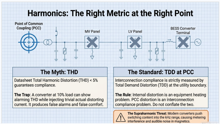
Harmonic compliance conversations go wrong in three predictable ways: the wrong metric, the wrong measurement point, and the wrong assumption about who owns the limit.
4.1 Current Distortion Is Measured as Total Demand Distortion
The governing North American framework expresses current distortion limits as total demand distortion, referenced to the maximum demand load current at the point of common coupling, rather than as total harmonic distortion referenced to the instantaneous fundamental. The distinction is not academic. A converter operating at ten percent of rating can show an alarming current total harmonic distortion figure while contributing a trivial amount of actual distorting current. Judging a project by that number produces both false alarms and false comfort.
The allowable total demand distortion is not a single value. It scales with the ratio of available short-circuit current at the point of common coupling to the maximum demand load current — a stiffer connection relative to the load is permitted more distortion, because the resulting voltage distortion is smaller. Individual harmonic orders carry their own limits, tightening as order increases, with even-order harmonics held to a fraction of the odd-order limits.
4.2 The Point of Common Coupling Is a Specific Place
Limits apply at the point of common coupling — the point where other customers are or could be served — not at a panel inside the facility, not at the converter terminals, and not at the low-voltage side of the campus transformer. Internal distortion is a facility engineering matter governed by equipment withstand and transformer heating, not by the interconnection limits. Conflating the two produces expensive filter specifications aimed at a problem the utility never had.
4.3 Voltage Distortion Limits Belong to the Utility
The framework assigns current limits to the customer and voltage limits to the system operator, with the voltage limits tightening as system voltage rises. In practice this becomes a shared responsibility: the customer’s current injection acting on the utility’s system impedance produces the voltage distortion the utility must hold. This is why background distortion measurement before energisation matters. A site that arrives at a point of common coupling already near the voltage distortion limit has far less headroom than the current-limit table alone suggests, and discovering that after commissioning is a mitigation project rather than a design decision.
4.4 Above the Classic Spectrum
Converter switching content in the range above the traditional harmonic measurement band — the supraharmonic region — is not addressed by the classic limit tables and is increasingly the source of real problems: interference with power line communication and metering, audible noise in magnetics, and interaction between converters from different manufacturers sharing a bus. A data center campus with a large storage converter, dozens of UPS modules, and hundreds of drives is exactly the environment where this appears. It should be measured, not assumed away.
5. The Data Center Complication
Standalone storage projects are analysed against a network. A data center campus adds a large, non-linear, dynamically varying load between the converter and the point of common coupling, and that changes the analysis in four specific ways.
5.1 Superposition Does Not Hold Naively
Harmonic currents from the storage converter and from the facility’s rectifier loads combine as phasors, not as magnitudes. Depending on the phase relationship at each order, they can partially cancel or reinforce. A study that adds distortion budgets arithmetically will be wrong in both directions, and the direction it is wrong in is not predictable without modelling the actual sources with their phase information.
5.2 The Facility Load Varies and So Does the Answer
IT load, mechanical load, and storage dispatch all vary independently. Compliance is not a single operating point. The harmonic study must evaluate the credible combinations — minimum facility load with the converter at full charge, full facility load with the converter idle, converter at full discharge during a demand response event — because the worst case for total demand distortion is often minimum demand rather than maximum, and the worst case for resonance is a specific capacitance and load damping combination that occurs at neither extreme.
5.3 Transformer Heating Is a Separate Calculation
Harmonic current increases transformer losses disproportionately, because eddy current loss rises with the square of harmonic order. The relevant assessment is a harmonic loss factor calculation against the transformer’s capability, or specification of a transformer rated for the harmonic duty. Data center campus transformers see this loading continuously, not intermittently, and a transformer selected on kVA alone in a high-distortion environment is a transformer with an unstated derate.
5.4 The Critical Load Is Sensitive to the Same Things
Voltage distortion and fluctuation at the campus bus propagate to the UPS input. UPS systems evaluate their source and will transfer to battery if input quality falls outside their acceptance window. A storage converter whose behaviour degrades campus voltage quality can therefore cause the facility’s own critical
power systems to abandon the utility source — the same class of failure discussed in the commissioning literature as a generator-to-UPS interaction, arriving through a different door.
6. Resonance: The Network Creates It, the BESS Excites It
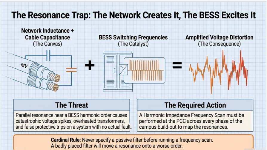
Resonance is the most misunderstood item on every BESS power quality summary. A converter does not create resonance. Resonance is a property of the network — the interaction between system and transformer inductance and the capacitance of cables, filters, and any power factor correction equipment. What the converter does is inject current at frequencies that may coincide with a resonant condition that already exists, at which point a modest injected current produces a large voltage.
6.1 Where the Capacitance Comes From on a Data Center Campus
- Medium-voltage cable. Campus distribution is cable, not overhead line, and often a great deal of it. Distributed cable capacitance is frequently the dominant capacitive element on a large campus and it grows with every phase of build-out.
- Converter output filter capacitance, from both the storage converter and any other inverter-based resource on site.
- Power factor correction and harmonic filter banks, where fitted.
- Surge capacitors and instrument transformer burden, minor individually and occasionally relevant in aggregate.
6.2 The Consequence of Getting It Wrong
A parallel resonance near a harmonic order the converter produces amplifies that order, producing voltage distortion far above what the injected current would suggest, overheating capacitors and transformers, and in the worst case causing protective device operation on a system with no fault. Because campus cable capacitance grows as phases are built, the resonant frequency migrates across the build-out. A study performed on Phase 1 does not describe the campus at Phase 3.
The study that answers this is a frequency scan
A harmonic impedance scan across the frequency range of interest, performed at the point of connection for each credible network configuration — each phase of build-out, each transformer and feeder switching state, minimum and maximum load damping — identifies where the resonant peaks sit relative to the orders the converter produces.
It is inexpensive during design and it is the only way to know whether a filter is needed, what it should be tuned to, and whether a proposed filter will move a resonance onto a worse order rather than away from one.
7. Voltage Fluctuation, Flicker, and Ramp Rate
Voltage fluctuation from a storage system is a power-change problem, not a harmonic problem, and it is straightforward to estimate. A change in the real and reactive power exchanged at a bus produces a voltage change governed by the change in apparent power relative to the short-circuit strength at that bus and the resistance-to-reactance ratio of the source impedance. Two consequences follow directly.
First, the magnitude of the fluctuation is set as much by the strength of the interconnection as by the size of the converter. The same converter produces a small voltage step on a strong system and a visible one on a weak system. Second, because the converter’s reactive capability is fast and controllable, much of the fluctuation is correctable by the converter itself if the control mode and the reactive priority are configured to do so. A storage system is more often the remedy for voltage fluctuation on a campus than the cause of it.
Flicker — the perceptibility of rapid voltage variation — is assessed by a standardised measurement method producing short-term and long-term severity indices, evaluated against planning levels the system operator sets. The relevant question for a data center campus is rarely the storage converter operating on a smooth dispatch signal; it is fast events. Step changes during demand response dispatch, transitions between charge and discharge, and coincidence with mechanical plant starting are the cases that need evaluation.
The design controls are ramp rate limiting configured in the converter, reactive support enabled with an appropriate priority, and, where the interconnection is genuinely weak, dynamic reactive equipment sized from the study rather than from a rule of thumb.
8. Grid Strength and Control Interaction
The ratio of available short-circuit strength at the point of interconnection to the rating of the inverter-based resource is the single most predictive number for whether a storage project will behave. A high ratio means the network holds voltage and the converter’s controls have ample stability margin. As the ratio falls, the converter’s own current injection begins to move the voltage it is measuring, the phase-locked loop and current controllers are operating against a network impedance comparable to their own control impedance, and stability margin erodes.
For a campus with a large storage converter, other on-site inverter-based generation, and a long radial supply, the effective strength seen by the converter can be considerably lower than a headline short-circuit figure at the utility substation suggests. Where multiple inverter-based resources share an interconnection, the aggregate matters, and system operators in the most affected regions have developed weighted and site-specific formulations precisely because the simple ratio overstates strength when converters interact.
The failure modes at low grid strength are not gradual degradation. They are oscillatory instability at frequencies that positive-sequence simulation cannot represent, unexpected tripping during and after nearby faults, and sustained interactions between converters from different manufacturers that neither exhibits alone. Sub-synchronous control interaction with series-compensated transmission is the best documented example and is not the only one.
This is why electromagnetic transient modelling is a requirement rather than a refinement at weak interconnections. Positive-sequence stability tools cannot represent converter control dynamics at the timescales where these phenomena live, and a study set that stops at load flow and short circuit has not addressed the risk that actually threatens the project.
9. Grid-Following and Grid-Forming Behaviour
Most storage converters in service today are grid-following: they synchronise to a measured voltage and inject a controlled current. They require a stable external voltage reference and they contribute nothing to system inertia or to establishing voltage on a de-energised network.
Grid-forming control instead regulates voltage magnitude and angle behind an impedance, presenting a voltage source to the network. The practical consequences relevant to a data center campus are substantial: grid-forming converters can operate at very low grid strength where grid-following control becomes unstable, can contribute to frequency stability, and can establish voltage on an islanded network, which makes campus islanding and black start technically feasible in a way grid-following equipment does not.
The trade-offs are real. Grid-forming operation imposes different current headroom requirements during transients, the control mode interacts with the protection design, and interconnection requirements and model validation practice for grid-forming resources are still maturing. The decision should be driven by the grid strength at the interconnection and by whether campus islanding is an operational requirement, and it should be made early, because it affects converter procurement, protection design, and the study scope.
10. Protection, Fault Behaviour, and Overvoltage
10.1 Fault Current Contribution
An inverter-based resource contributes fault current limited by its control to a small multiple of rated current, for a controlled duration, with a waveform that is not the decaying symmetrical contribution a synchronous machine produces. Overcurrent protection philosophies built around the assumption of substantial fault current from every source do not translate. Where the storage converter is a significant portion of the source capacity at a campus bus, the coordination study must model the converter’s actual current-limited contribution rather than an equivalent machine, and directional, differential, or communication-assisted schemes may be required where overcurrent alone cannot discriminate.
10.2 Ground Fault Overvoltage and Effective Grounding
When a converter and its interconnection transformer remain energised on a portion of the system that has been separated from the utility source by an upstream device operating for a ground fault, the grounding arrangement of the interconnection transformer determines whether the unfaulted phases rise to a level the system’s equipment insulation and surge arresters can tolerate. This is a design decision — winding configuration, grounding transformer, neutral treatment — that must be settled against the utility’s grounding practice, and it is a common cause of late-stage interconnection redesign when it is deferred.
10.3 Load Rejection and Transient Overvoltage
A converter charging at full rate that suddenly loses its source, or discharging into a load that disappears, produces a transient the design must bound. Combined with transformer energisation inrush, sympathetic inrush between adjacent transformers, and the interaction with surge arrester duty, this belongs in the transient study scope rather than in the assumption that converter controls will handle it.
10.4 Islanding and Interconnection Compliance
Unintentional islanding detection, ride-through obligations during voltage and frequency excursions, and disturbance monitoring and reporting obligations attach to the resource according to its size, voltage level, and the interconnection framework it falls under. The requirements differ materially between a distribution-connected resource and a transmission-connected one, and between market regions. Establishing which framework applies is a first-week question, not a permitting-phase question, because it drives model requirements, telemetry, protection, and testing scope.
11. The Study Set
The following is the study scope an owner should expect for a storage system interconnected at a data center campus. Scope varies with size, voltage, and jurisdiction, but a proposal that omits several of these is a proposal that has deferred risk rather than priced it.
| Study | What it answers | Why it matters at a data center campus |
|---|---|---|
| Load flow and voltage regulation | Steady-state voltages and flows across dispatch and build-out cases | Campus load grows in phases; the acceptable case at Phase 1 is not the governing case |
| Short circuit | Fault duties with the converter’s current-limited contribution modelled correctly | Equipment ratings and the validity of the existing coordination scheme |
| Protective coordination and selectivity | Whether devices discriminate with a current-limited source present | Data center coordination requirements are stringent and the storage addition invalidates the prior study |
| Arc flash | Incident energy with the converter contribution and the revised settings | Labels and maintenance procedures must be updated; a study revision is not optional |
| Harmonic frequency scan | Where network resonances sit for each configuration and build phase | Campus cable capacitance is large and grows; resonance migration is the specific risk |
| Harmonic injection and compliance | Total demand distortion at the point of common coupling across operating combinations | Compliance is a set of operating points, not one; background distortion must be measured first |
| Flicker and voltage fluctuation | Voltage step and flicker severity from dispatch and transitions | Weak interconnections and demand response step changes |
| Transient stability | Behaviour through faults and disturbances at the system level | Required by most interconnection processes above threshold sizes |
| Electromagnetic transient analysis | Control interaction, weak-grid stability, ride-through, and switching transients | The only tool that represents converter control dynamics; mandatory at low grid strength |
| Effective grounding and overvoltage | Ground fault overvoltage and transformer grounding arrangement | A late finding here forces transformer redesign and reprocurement |
| Transformer harmonic loading | Derating or harmonic-duty rating for campus transformers | Continuous non-linear loading, not intermittent |
| Ground grid and step/touch | Safety of the grounding system with the added equipment and fault duty | New equipment pads, new fault contributions, and personnel access |
12. The Mitigation Toolkit
Mitigation should follow from the studies, in order of cost and intrusiveness. Specifying a filter before running a frequency scan is the most common and most expensive sequencing error in this work.
| Measure | Addresses | Notes and trade-offs |
|---|---|---|
| Converter selection and control tuning | Distortion spectrum, stability margin, ramp behaviour | The cheapest and most effective lever, available only before procurement closes |
| Ramp rate limiting | Voltage fluctuation and flicker | Configured in the converter; may conflict with market service obligations, so settle the use case first |
| Reactive support and voltage control mode | Voltage fluctuation and steady-state regulation | Uses converter capability already purchased; check the real-versus-reactive priority setting |
| Transformer winding configuration and phase shift | Cancellation of specific harmonic orders across parallel converter groups | Effective where multiple converter groups exist; requires the arrangement to be designed, not inherited |
| Detuned or tuned passive filtering | Specific harmonic orders and resonance placement | Must be designed against the frequency scan; a badly placed filter moves resonance onto a worse order |
| Active filtering | Broadband distortion including varying spectra | Higher cost and complexity; appropriate where the spectrum varies with dispatch |
| Series reactance | Resonance detuning and fault duty | Introduces voltage drop and losses |
| Dynamic reactive compensation | Weak-grid voltage support beyond converter capability | Sized from the study; significant cost, justified by grid strength not by preference |
| Point-of-connection relocation | Grid strength, resonance, and distortion sharing | Sometimes the cheapest fix and only available while the single line is still on paper |
13. Measurement and Compliance Verification
A compliance claim that rests on simulation alone is incomplete. The verification sequence that holds up is straightforward and is frequently skipped.
- Measure background power quality at the point of common coupling before the storage system is energised, using instrumentation of the appropriate measurement class, over a period long enough to capture the site’s weekly load cycle. Without this baseline, no post-energisation measurement can distinguish the storage system’s contribution from what was already there.
- Record the facility’s own distortion contribution before energisation as well. On a data center campus this is substantial and it is the owner’s, not the utility’s.
- After energisation, measure across the operating envelope — charge, discharge, idle, and transition — at the load conditions the study identified as governing, not merely at a convenient one.
- Evaluate against the limits using the statistical basis the standard specifies rather than instantaneous peaks. Compliance frameworks are written around percentile values of aggregated measurement intervals, and a single high sample is not a violation any more than a single low sample is a pass.
- Repeat the assessment at each phase of campus build-out. Cable capacitance, load, and short-circuit strength all change, and the resonance condition moves with them.
- Retain the measurements. When a power quality dispute arises with the utility or with an equipment vendor, the party holding a defensible baseline and a documented commissioning survey is in a completely different position from the party holding a simulation report.
14. Reading the Graphic Correctly
The four-panel summaries of BESS power quality effects that circulate widely are directionally useful and technically loose in ways that matter. Five clarifications.
Clarification 1 — The metric is total demand distortion, not THD
Stating that a storage system "increases THD levels" points at the wrong number. Interconnection compliance for current is assessed as total demand distortion at the point of common coupling, referenced to maximum demand load current. Voltage total harmonic distortion is a separate limit belonging to the system operator. Using the terms interchangeably produces both unnecessary filter purchases and missed non-compliance.
Clarification 2 — The converter does not create resonance
Resonance is created by network inductance and capacitance. The converter excites a condition that already exists. This matters practically because it locates the fix: the answer is a frequency scan and, if required, a change to the network — filter, reactance, or point of connection — not a search for a better-behaved converter.
Clarification 3 — Storage is usually the cure for voltage fluctuation, not the cause
A converter with fast reactive control and configurable ramp limits is one of the most effective voltage stabilisation devices available at a campus bus. Presenting voltage fluctuation solely as a risk of adding storage inverts the more common engineering reality, where the storage system is dispatched to correct fluctuation caused by the facility’s own load.
Clarification 4 — The dominant risks are missing from the four panels
Harmonics, voltage fluctuation, and resonance are the classic list. On modern projects the risks that actually stop or delay work are grid strength and converter control interaction, ground fault overvoltage and the interconnection transformer grounding arrangement, ride-through compliance and disturbance monitoring obligations, and model availability and validation. None of these appear on a four-panel summary and all of them are schedule-critical.
Clarification 5 — Compliance is a set of operating points
Every one of these effects varies with dispatch, facility load, network configuration, and build phase. A single-case study and a single commissioning measurement are not evidence of compliance; they are evidence of one condition. The study set and the measurement protocol both have to be built around the envelope.
15. Keentel Data Center and Storage Engineering Services
Keentel Engineering provides the interconnection engineering, power system studies, and facility electrical design that determine whether storage added to a data center campus behaves as intended and can be approved. Our practice in this area covers the following.
15.1 Interconnection and Point-of-Interconnection Engineering
- Large-load and generation interconnection support: load and resource characterisation, application-stage technical packages, coordination with the serving utility, transmission provider, and system operator, and management of study-phase technical questions.
- Point-of-interconnection design, substation design, and medium-voltage collection and campus distribution design for phased data center developments.
- Interconnection transformer configuration and effective grounding assessment, settled early rather than discovered during utility review.
15.2 Power System Studies
- Load flow, short circuit, protective coordination and selectivity, and arc-flash analysis, with inverter-based resources modelled as current-limited sources rather than as equivalent machines.
- Harmonic frequency scan and injection studies across build-out phases and operating combinations, with compliance assessed at the correct point using the correct metric.
- Flicker and voltage fluctuation assessment, grid strength evaluation, and transient stability analysis.
- Electromagnetic transient modelling for control interaction, weak-grid stability, ride-through verification, and switching and overvoltage transients, using validated manufacturer models.
- Transformer harmonic loading assessment, insulation coordination, and ground grid and step-and-touch analysis.
15.3 Facility Electrical Design and Owner’s Engineer Support
- Campus distribution topology, UPS and generator plant integration with storage, and white-space power distribution designed against the availability and maintainability requirements.
- Converter and equipment specification including model deliverable requirements, ride-through and control configuration, and factory test scope.
- Design review of EPC and vendor submittals, QA/QC of third-party study packages, commissioning specification and test script support, and power quality baseline and verification survey scoping.
- NERC compliance support for registered resources, including disturbance monitoring, ride-through, and model-related obligations.
Keentel Engineering holds a Florida Certificate of Authorization and maintains offices in Tampa, Austin, Sacramento, and Baltimore, supporting projects across the interconnections.
16. Frequently Asked Questions
Q1. Does adding a BESS really change grid behaviour, or is that marketing?
It genuinely does, but not because of the battery. A storage system adds a power-electronic converter that injects controlled current, contributes limited and differently shaped fault current, adds filter capacitance to the network, and imposes new dynamics through its control loops. Every one of those is a change the studies have to account for. The energy capacity, by contrast, changes almost nothing about grid behaviour — it changes duration.
Q2. Why is the inverter more important than the battery?
Because the grid never sees the battery. It sees the converter’s output. Switching frequency and modulation set the distortion spectrum, filter design sets the capacitance and the filter resonance, control bandwidth and phase-locked loop tuning set stability margin, and the current limit sets fault contribution. Two systems with identical cells and different converters behave differently in every study.
Q3. What is the correct harmonic metric for compliance?
Total demand distortion for current, at the point of common coupling, referenced to the maximum demand load current — not total harmonic distortion referenced to the instantaneous fundamental. Voltage distortion limits are separate and belong to the system operator. A converter at light load can show a large current THD figure while injecting negligible distorting current; judging compliance on that number is a common and avoidable error.
Q4. Where exactly do the limits apply?
At the point of common coupling — where other customers are or could be served. Not at the converter terminals, not at an internal panel, and not at the transformer low-voltage side. Internal distortion still matters for equipment heating and for the facility’s own UPS behaviour, but it is governed by equipment withstand, not by the interconnection limits.
Q5. Does a data center campus make the harmonic analysis harder?
Substantially. The campus is already a large non-linear load from UPS rectifiers, IT power supplies, and drives, and it sits behind a long medium-voltage cable system with significant capacitance. The converter’s injection combines with the existing sources as phasors, so it can cancel or reinforce depending on phase, and the network it injects into may already have a resonance near an order it produces.
Q6. Can a BESS cause resonance?
It cannot create one. Resonance is a property of the network inductance and capacitance. What the converter can do is inject current at a frequency where a resonance already sits, which turns a small current into a large voltage. The converter’s own output filter capacitance does participate in forming the network, so it shifts where resonance sits — but the condition is a network property and the fix is a network fix.
Q7. Where does the capacitance on a data center campus come from?
Mostly medium-voltage cable. Campus distribution is cable rather than overhead line and there is often a great deal of it, with distributed capacitance that grows with each phase of build-out. Converter output filters, any power factor correction, and surge capacitors add to it. The practical consequence is that the resonant frequency moves as the campus grows, so a study performed for Phase 1 does not describe the campus at Phase 3.
Q8. What study identifies resonance?
A harmonic impedance frequency scan at the point of connection, run for each credible network configuration: each build phase, each transformer and feeder switching arrangement, and minimum and maximum load damping. It shows where the resonant peaks sit relative to the orders the converter produces, and it is the only sound basis for deciding whether a filter is needed and what it should be tuned to.
Q9. Will a BESS cause voltage flicker at my campus?
Rarely from steady dispatch. The cases worth evaluating are fast events: step changes during demand response, charge-to-discharge transitions, and coincidence with mechanical plant starting. The magnitude depends as much on the short-circuit strength at the connection as on the converter rating. Ramp rate limiting and reactive support configured in the converter address most of it.
Q10. Is storage more likely to fix voltage problems than cause them?
On a data center campus, usually yes. A converter with fast reactive control is one of the more capable voltage stabilisation devices available at a campus bus, and it is frequently dispatched to correct fluctuation the facility’s own load creates. The risk framing in the popular summaries inverts the common case, though the risk is real on weak interconnections.
Q11. What is grid strength and why does everyone ask about it?
It is the ratio of available short-circuit strength at the interconnection to the rating of the inverter-based resource. It predicts whether the converter’s controls have adequate stability margin. As it falls, the converter’s own current begins to move the voltage it is measuring, and the failure modes are oscillatory instability and unexpected tripping rather than gradual degradation. Where multiple inverter-based resources share an interconnection, the aggregate governs, and simple ratios overstate strength.
Q12. When is electromagnetic transient modelling actually required?
Whenever grid strength is low, whenever multiple inverter-based resources share an interconnection, whenever ride-through behaviour must be verified rather than asserted, and wherever the interconnecting entity requires it — which is increasingly the default above threshold sizes. Positive-sequence stability tools cannot represent converter control dynamics at the timescales where control interaction lives, so a study set that stops at load flow and short circuit has not addressed the risk most likely to stop the project.
Q13. What is grid-forming control and do I need it?
Grid-forming converters regulate voltage magnitude and angle rather than injecting a controlled current against a measured voltage. They can operate at very low grid strength, contribute to frequency stability, and establish voltage on an islanded network — which makes campus islanding and black start feasible. Whether you need it depends on the grid strength at your interconnection and whether islanded operation is an operational requirement. Decide early, because it affects procurement, protection, and study scope.
Q14. How does storage change protection design?
The converter contributes fault current limited to a small multiple of rated current for a controlled duration, with a waveform unlike a synchronous machine’s contribution. Overcurrent schemes that assume substantial fault current from every source may not discriminate. Where the converter is a significant portion of source capacity at a bus, expect the coordination study to be revisited and directional, differential, or communication-assisted schemes to be considered.
Q15. What is ground fault overvoltage and why does it delay projects?
If the converter and its interconnection transformer stay energised on a section separated from the utility source during a ground fault, the transformer’s grounding arrangement determines how far the unfaulted phase voltages rise. If the arrangement does not match the utility’s grounding practice, equipment insulation and surge arresters can be overstressed. It delays projects because it is often raised during utility review, after the transformer has been specified and ordered.
Q16. Does the storage system affect my UPS systems?
It can, indirectly. UPS systems evaluate input quality and transfer to battery when it falls outside their window. Voltage distortion or fluctuation at the campus bus propagates to the UPS input, so a converter degrading campus voltage quality can push the facility’s critical power systems off the utility source. This is the same class of interaction as the generator-to-UPS problem seen during integrated testing, arriving through a different path.
Q17. Do I need to measure power quality before energising?
Yes, and it is the step most often skipped. Without a baseline at the point of common coupling and a record of the facility’s own contribution, no post-energisation measurement can separate what the storage system added from what was already present. In a dispute with a utility or a vendor, the baseline is the difference between an argument and an answer.
Q18. How is compliance actually assessed from measurements?
On a statistical basis over a measurement period long enough to cover the site’s load cycle, using percentile values of aggregated intervals rather than instantaneous peaks, with instrumentation of the appropriate measurement class. A single high sample is not a violation, and a single clean snapshot is not a pass.
Q19. Does the analysis change if the storage sits inside the UPS path rather than on the campus bus?
Considerably. Storage inside the critical power path at low voltage, not operating in parallel with the utility, is primarily a facility design and commissioning problem. Storage on the campus medium-voltage bus operating in parallel with the utility is an interconnection problem, with study obligations, model requirements, protection requirements, and compliance obligations that attach according to size, voltage, and jurisdiction. Establish which case applies before the study scope is written.
Q20. What is the highest-value thing to get right early?
Two things, both before the converter is ordered. First, settle the use case, because it determines rating, duty cycle, point of connection, and interconnection pathway. Second, write the model deliverable into the procurement specification — validated positive-sequence and electromagnetic transient models, with the right to use them for the required studies. Almost every schedule problem in this work traces back to a study that could not be run because the model was not available.
Notice and Disclaimer
This document is original technical content prepared by Keentel Engineering LLC for general professional information. It is not project-specific engineering advice and does not constitute a design, a study, an interconnection application, or a compliance determination for any particular facility. Study scope, interconnection requirements, and power quality obligations vary by system operator, utility, voltage level, resource size, and jurisdiction, and the requirements applicable to a specific project govern that project.
Standards and regulatory references are provided by subject for orientation. The current published edition of each standard and the requirements adopted by the applicable authority, utility, or system operator govern. Equipment behaviour, ratings, and model characteristics must be taken from the specific manufacturer’s validated data for the equipment selected.
Keentel Engineering LLC is an independent engineering consultancy. Reference to any standard, code, market rule, industry organisation, or equipment category in this document does not imply affiliation with, endorsement by, or sponsorship from any such organisation or manufacturer.

About the Author:
Sandip "Sonny" R. Patel, P.E.
IEEE Senior Member · Founder & CEO, Keentel Engineering
In 1995, Sonny Patel earned his Electrical Engineering degree from the University of Illinois. But degrees don't build legacies — action does.
For three decades, he has worked the power industry from every side of the table: 16 years as a utility engineer at Exelon/Commonwealth Edison; generation leadership across hydroelectric, industrial steam turbine, and a 9 GW renewable fleet; NERC Regional Entity Senior Compliance Engineer and Audit Team Lead, auditing some of the nation's largest utilities; and testing and commissioning lead on equipment up to 765 kV — the very top of the North American grid.Utility. Generator. Regulator. Consultant. Few engineers have seen all four seats. Fewer still have sat in them.
His experience spans nuclear, hydro, conventional generation, renewables, oil and gas, mining — and today's data centers, where he is authoring a three-book series on data center design. He is a Licensed Professional Engineer in six states and a Licensed Electrical Contractor in Florida (Unlimited EC) — he doesn't just design the work; he's qualified to stand behind its execution.Today, as Founder and CEO of Keentel Engineering, Sonny leads a nationwide team of engineers delivering substation design, power system studies, NERC compliance, and commissioning — done right, coast to coast.Three decades. Every side of the table. One standard: accountable engineering.
Services

Let's Discuss Your Project
Let's book a call to discuss your electrical engineering project that we can help you with.
About the Author:
Sandip "Sonny" R. Patel, P.E.
IEEE Senior Member · Founder & CEO, Keentel Engineering
In 1995, Sonny Patel earned his Electrical Engineering degree from the University of Illinois. But degrees don't build legacies — action does.
For three decades, he has worked the power industry from every side of the table: 16 years as a utility engineer at Exelon/Commonwealth Edison; generation leadership across hydroelectric, industrial steam turbine, and a 9 GW renewable fleet; NERC Regional Entity Senior Compliance Engineer and Audit Team Lead, auditing some of the nation's largest utilities; and testing and commissioning lead on equipment up to 765 kV — the very top of the North American grid.
Utility. Generator. Regulator. Consultant. Few engineers have seen all four seats. Fewer still have sat in them.
His experience spans nuclear, hydro, conventional generation, renewables, oil and gas, mining — and today's data centers, where he is authoring a three-book series on data center design. He is a Licensed Professional Engineer in six states and a Licensed Electrical Contractor in Florida (Unlimited EC) — he doesn't just design the work; he's qualified to stand behind its execution.
Today, as Founder and CEO of Keentel Engineering, Sonny leads a nationwide team of engineers delivering substation design, power system studies, NERC compliance, and commissioning — done right, coast to coast.Three decades. Every side of the table. One standard: accountable engineering.
Leave a Comment
Thank you for contacting us.
We will get back to you as soon as possible.
We will get back to you as soon as possible.
Oops, there was an error sending your message.
Please try again later.
Please try again later.
Related Posts

By SANDIP R PATEL
•
October 3, 2026
Engineering guide to PRC-028 disturbance recording, PRC-029 ride-through and PRC-030 event detection for inverter-based resources.

By SANDIP R PATEL
•
October 3, 2026
A practical guide to SSO classification, SSR, PEDI, Wind-SSCI, EMT analysis, mitigation and protection based on CIGRE TB 909.

By SANDIP R PATEL
•
October 3, 2026
Learn ERCOT generator testing for PFR, MOD-025 and MOD-026/027, including staged tests, capability verification, dynamic models and field testing.

By SANDIP R PATEL
•
October 3, 2026
Learn how PV string I-V curve testing identifies hidden solar performance losses, including soiling, shading, mismatch, degradation, and wiring faults.

By SANDIP R PATEL
•
October 3, 2026
Learn how active harmonic filters work, how to size AHF systems, reduce VFD harmonics, calculate losses, and meet IEEE 519 TDD limits at the PCC.
By SANDIP R PATEL
•
October 3, 2026
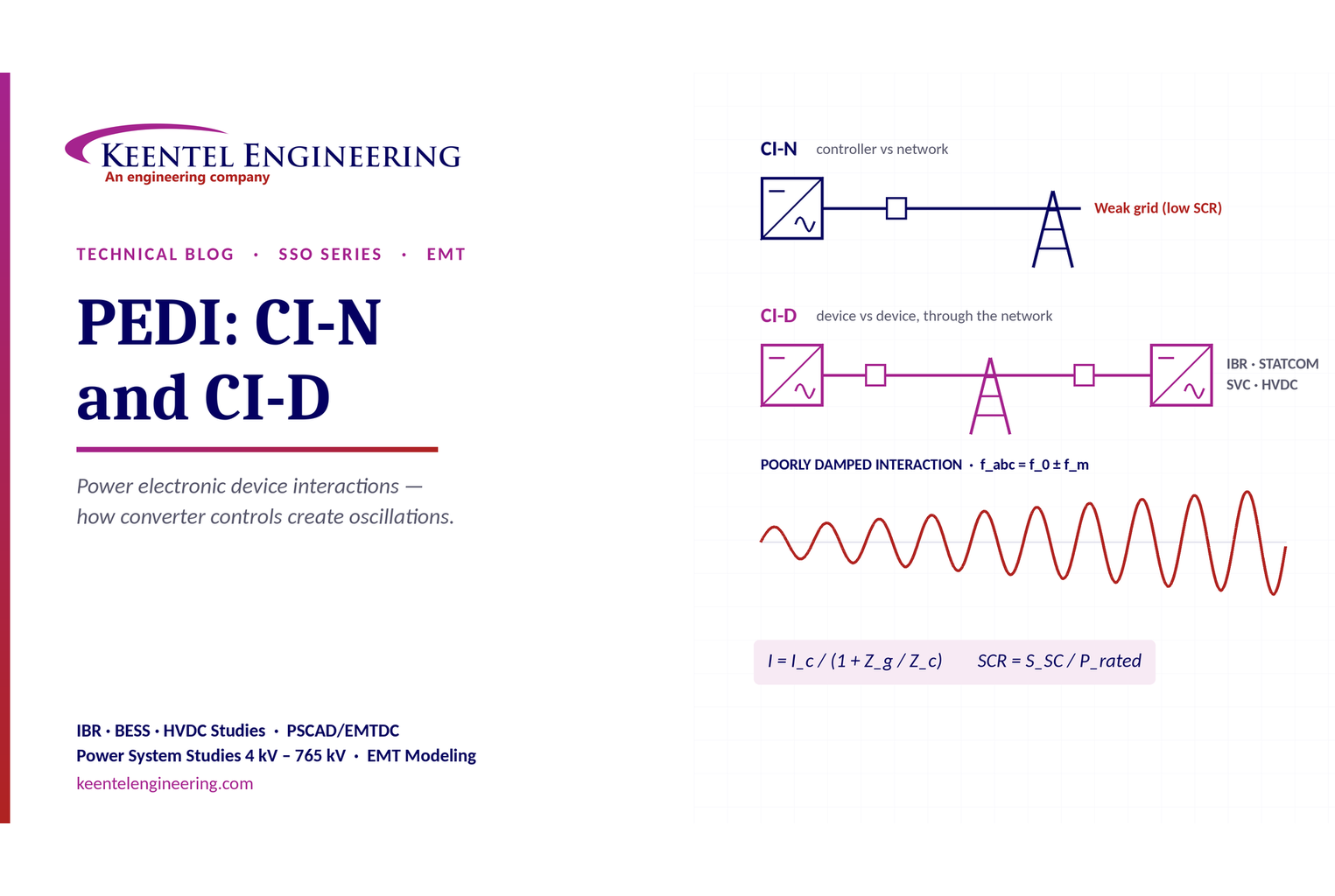
Learn power electronic device interactions (PEDI), including CI-N and CI-D, weak-grid stability, SCR, EMT studies, impedance analysis and mitigation for IBRs.
By SANDIP R PATEL
•
October 3, 2026
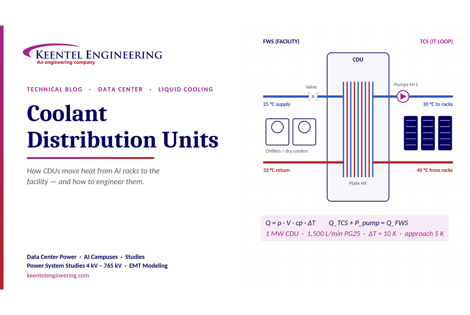
Learn how data center coolant distribution units (CDUs) work, including FWS and TCS loops, heat transfer, sizing, redundancy and liquid cooling for AI data centers.
By SANDIP R PATEL
•
October 3, 2026
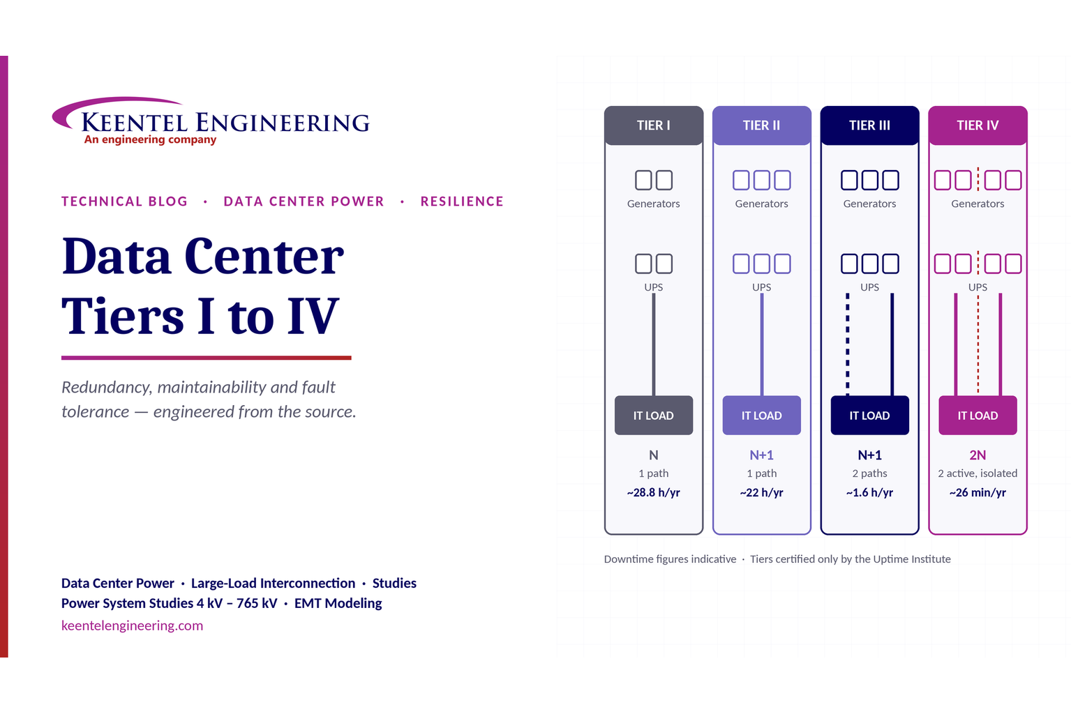
Compare Data Center Tiers I–IV, including redundancy, uptime, Tier III concurrent maintainability, Tier IV fault tolerance, UPS, generators and power design.

By SANDIP R PATEL
•
October 3, 2026
Learn how BESS supports grid stability through fast frequency response, voltage support, oscillation damping, black start, grid-forming controls and EMT studies.





