
A Coordinated Electric System Interconnection Review—the utility’s deep-dive on technical and cost impacts of your project.
Challenge: Frequent false tripping using conventional electromechanical relays
Solution: SEL-487E integration with multi-terminal differential protection and dynamic inrush restraint
Result: 90% reduction in false trips, saving over $250,000 in downtime
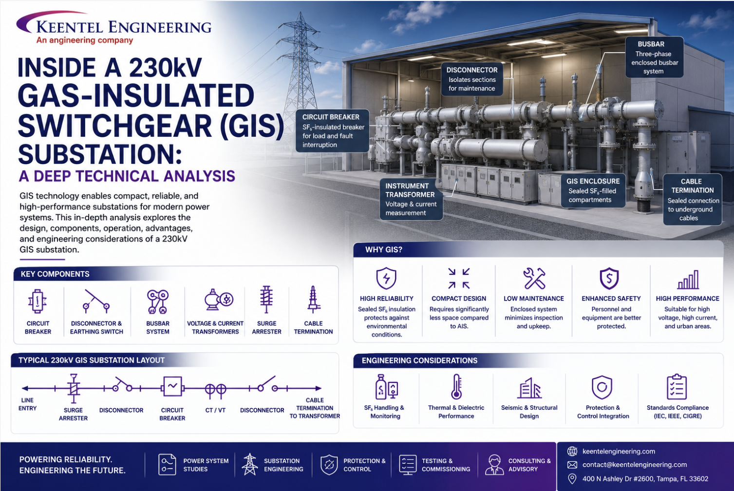
Inside a 230kV Gas-Insulated Switchgear (GIS) Substation: A Deep Technical Analysis
May 30, 2026 | Blog
Introduction and System Architecture
A modern 230kV substation built on outdoor Gas Insulated Switchgear (GIS) topology represents one of the most densely engineered nodes in any high-voltage transmission network. The reference design analyzed here specifies a comprehensive 245kV implementation, structured around Siemens Energy's 8DN9 and 8DQ1 switchgear platforms — two of the most widely deployed GIS modules in utility-scale substations today.
The deployment is engineered to accommodate a rated maximum continuous voltage of 245kV at a nominal frequency of 60Hz, with permissible frequency variations between 57.5Hz and 62.5Hz.
The architecture is fundamentally aligned with digital substation paradigms, incorporating an IEC 61850-based Power Management System (PMS) to facilitate advanced Substation Configuration Language (SCL) methodologies and robust IT/OT convergence. The GIS equipment utilizes sulfur hexafluoride (SF6) as the primary dielectric medium, employing a three-phase encapsulated main busbar configuration, while ancillary equipment such as circuit breakers and disconnect switches employ single-phase encapsulation.
This article unpacks the engineering choices that go into such a substation — from the dielectric pressure of the SF6 gas to the bend radius of lightning down-conductors — and closes with three case studies and an FAQ.
1. Primary Equipment Specifications
The primary high-voltage apparatus is subject to rigorous electromechanical and dielectric parameters. The overall insulation level is defined by a Basic Impulse Level (BIL) of 1050kV peak for phase-to-earth gaps and 1200kV peak across open isolating distances. The rated short-duration power frequency withstand voltage is established at 460kV rms for phase-to-earth constraints and 530kV across open gaps. The short-time withstand current for the primary circuit is 50kA rms for 3 seconds, coupled with a dynamic peak withstand current of 130kA.
1.1 Circuit Breakers
Circuit breaker variants vary by functional bay:
- Transformer and capacitor bank feeder breakers: 3150A minimum continuous current.
- Line and bus coupler breakers: 4000A.
- Electrical endurance class: E2.
- Mechanical endurance: more than 10,000 operations.
- Rated operating sequence: O-0.3sec-CO-3min-CO.
- Actuation: single-pole operated, dual trip coils, 125V DC auxiliary supply (+10%, -15%).
Breaking and opening times differ by variant:
- 8DN9: breaking time 48.7ms, opening time 33±3ms.
- 8DQ1: opening time 18±2ms.
Capacitor bank breakers are augmented with a Phase Synchronizing Device (PSD) to manage current-zero switching and mitigate capacitive switching transients.
1.2 Disconnect and Earthing Switches
Disconnect switches (DS) are motor-operated, supporting both manual and electrical gang operation, with mechanical endurance of 1,000 cycles (Class M1). They can interrupt the charging current of the connected GIS bus, with a magnetizing and capacitive current make/break capacity of 0.25A.
Standard earthing switches (ES) and high-speed grounding switches (HSGS) are rated at 1250A continuous and 50kA for 3 seconds short-time withstand. HSGS units carry electrical endurance class E1 and are capable of at least two full fault closing operations. The HSGS spring charging time is 6 seconds, achieving closing and opening times of less than 60ms — compared to the standard grounding switch operation time of less than 4 seconds.
1.3 Instrument Transformers and Bushings
Voltage Transformers (VTs) are SF6 gas-insulated, electromagnetic types designed for three-phase, phase-to-ground applications within an effectively grounded system. They incorporate a disconnecting link for isolation during high-voltage AC testing and exhibit a partial discharge value of ≤ 5 pC at 1.2U/√3. VTs step the 230kV primary down to 115V or 115/√3V secondary potentials, with metering windings delivering 50VA at accuracy class 0.2 and protection windings delivering 50VA at 3P. They are rated for a continuous voltage factor of 1.2 and a short-duration factor of 1.5 for 30 seconds.
Current Transformers (CTs) use variable ratios — 1000-2000-3000/1 A up to 1000-2000-3000-4000/1 A. Core 1 is designated for metering at 0.2S class and 15VA output, operating at 120% extended primary current. Protection cores are Class PX, with specific knee-point voltages and internal secondary resistances tuned to prevent magnetic saturation during asymmetrical fault currents. For example, the 4000/1 A ratio PX core exhibits a knee-point voltage of 2400V and an internal resistance of 20 Ohms.
SF6 gas-to-air bushings for overhead line interfaces use brown porcelain insulators with a minimum centerline phase-to-phase spacing of 3000mm. They support 4000A continuous current and provide creepage exceeding 31 mm/kV, with an external housing insulation leakage distance greater than 2100mm. Cantilever operational load is 2500N horizontal and 1500N vertical. The 245kV cable sealing ends comply with IEC 62271-209, accommodating cross-sections up to 1000 sq.mm.
1.4 SF6 Gas Parameters and Busbar Characteristics
SF6 pressure regulation is enforced across independent compartments:
- 8DN9 circuit breakers: nominal filling pressure 6.9 bar, density minimum 6.2/6.4 bar.
- 8DQ1 (3150A) breakers: 5.6 bar nominal.
- Other GIS compartments: 6.1 bar.
- Rupture discs: calibrated to burst between 12.2 and 13.4 bar.
- General design pressure: 8.5 to 9.0 bar depending on the module.
The GIS busbar is a solid aluminum conductor with an outer diameter of 80mm. Electrical parameters: inductance 0.2 ± 0.04 μH/m, resistance 8 μΩ/m, surge impedance 60 ±12Ω, capacitance 50 ±10 pF/m. The outer enclosure is 561mm in diameter with a wall thickness of 13mm.
2. Protection, Control, and Telecommunication Architecture
The secondary protection schemes and control networks form the deterministic infrastructure of the substation. The Network Data Management Equipment (NDME) processes analog and digital signals from Intelligent Electronic Devices (IEDs) across the installation.
2.1 NDME Signal Input Configuration
Each protection zone has dedicated analog and digital channel inputs:
Busbar Protection: Three analog channels (LV Phase A, B, C). Digital channels: Bus Differential Trip (87B), Relay Fail, DC Fail, AC Fail, Voltage Low.
Breaker Failure Protection (integrated with double busbar scheme): Breaker Fail Start, Breaker Fail Trip, Breaker Fail Retrip, Autorecloser Successful, Autorecloser Not Ready, Definitive Trip, Relay Fail, DC Fail, AC Fail.
Shunt Capacitor Protection: Analog channels for Phase A/B/C voltages and currents plus neutral current. Digital channels: Overcurrent Start/Trip, Star Unbalance Trip, Overvoltage Alarm/Trip, VT Fail, Relay Fail, DC Fail, AC Fail.
Transformer Protection: Eighteen analog channels covering primary and secondary current and voltage phasors, plus HV and MV bushing CT inputs. Digital channels include General Start, Differential Trip (87T), Restricted Earth Fault Trip (64T), Primary and Secondary Overcurrent, Overfluxing Protection Trip, Distance Trip, Ground Protection Trip, Tertiary Winding Protection Trip, plus mechanical inputs from Buchholz Main Tank, Buchholz OLTC, Pressure Relief, Winding Temperature, and Oil Temperature.
Line Differential Protection: Phase A/B/C voltages plus main breaker and tie breaker currents. Digital channels facilitate General Start, Differential Trip, Trip via DTT, Communication Failure, Distance Zone 1/2/3 Trips, Switch-Onto-Fault, Power Swing Block, DTT Receive, Autoreclose Initiate, Autoreclose Block, Stub Protection Enable, Distance Protection Block.
All interface connections between the NDME and individual protection relays are hardwired to ensure deterministic signal latency.
2.2 Substation Automation System and Telecommunications
The Power Management System (PMS) defines the IEC 61850 network topology, with redundant NDME panels and protection relays connected via industrial Ethernet switches. A GPS panel supplies the IRIG-B timing signal for precise event stamping and synchrophasor measurement alignment across the PMS Master Station and PMS Slave.
The telecommunication layer integrates a Traveling Wave Fault Locator (TWFL) network linking the substation to its peer substations. TWFL panels at each site derive precise timing from local GPS receivers and interface via optical ground wire (OPGW) transmission lines. OPGW splice boxes facilitate the transition of optical fibers into the substation control room.
3. Civil and Structural Engineering Analysis
3.1 Structural Steel and Hardware
All structural steel angles with a leg width of 200mm or greater are fabricated from ASTM A572 Grade 50 steel, providing the elevated yield strength required for high-stress members such as the incoming line gantry. Remaining structural angles use ASTM A36 steel. All structural members, plates, bolts, nuts, and accessories undergo hot-dip galvanization. Connections including stub base plates adhere to the AISC 2015 edition or equivalent local standards.
3.2 Foundation and Concrete Reinforcement
Concrete mix class dictates a minimum compressive strength of 30 MPa (f'c = 30 MPa). Reinforcing steel complies with ASTM A615 Grade 60, ensuring a minimum yield strength of 420 MPa (fy = 420 MPa).
Class B tension splices are mandatory for all rebar unless otherwise noted. Lap splice lengths vary by bar diameter (D10 through D32) and structural location. For example, a D16 bar at the top of a foundation with 30mm clear cover and 150mm center-to-center spacing requires a 1180mm lap splice. Top bars — horizontal bars with more than 300mm of fresh concrete cast beneath them — require extended development lengths due to bleed water and laitance accumulation.
Concrete cover depths:
- 75mm clear cover for surfaces cast directly against earth or mud mats, and for sides/bottoms of footings.
- 50mm for formed surfaces exposed to earth or weather.
Reinforcing steel cut to accommodate blockouts must be replaced with an equivalent cross-sectional area placed symmetrically around the opening, extending a full Class B splice length past the void. PVC waterstops (e.g., Sika Hydrotite CJ-0220 or CETCO Waterstop-RX 101 hydrophilic variants) are mandatory at construction joints.
4. High-Voltage Clearances and Spatial Arrangements
The spatial geometry is governed by rigorous minimum clearance parameters to suppress dielectric breakdown and flashover. A universal requirement of R2100 MIN (2100mm radius) applies for phase-to-phase and phase-to-ground isolation, systematically applied across all three phases for surge arresters, capacitive voltage transformers (CVTs), current transformers, and bus post insulators (BPI).
The incoming line gantry terminates QUAD 795MCM ACSR CONDOR conductors at the insulator connection point. The gantry supports the OPGW at the uppermost peaks, providing a shielding angle over the phase conductors. Conductors descend to substation equipment via compression-type connectors.
The capacitor bank layout vertically stacks capacitor units on base insulators. The neutral CT sits adjacent to the stack, while damping reactors and surge arresters form the protective boundary. Equipment spacing: 2650mm between the neutral CT centerline and the capacitor unit centerline, and 4865mm separating the capacitor unit from the primary surge arrester.
5. Grounding and Lightning Protection Implementation
5.1 Earthing Network
The primary subterranean ground grid consists of a 150 sq.mm bare copper conductor, buried 500mm below finished grade to establish an equipotential plane across the substation footprint. Cross and tee junctions within the grid are executed exclusively via exothermic welding to ensure zero-maintenance, low-resistance mechanical joints.
Above-ground equipment and structural steel are bonded to the buried grid using 150 sq.mm PVC-insulated copper conductors. The PVC insulation on risers mitigates accelerated galvanic corrosion at the air-soil interface.
Power transformers mandate two independent sets of grounding rods for the main body, plus two additional sets dedicated to high-voltage neutral earthing. Ground wells employ a 150mm standard casing drilled to a depth of 30 meters, populated with a 20mm copper-bonded ground rod and backfilled with Bentonite grounding enhancement material to achieve the target earth resistance.
5.2 Lightning Protection
The lightning protection scheme intercepts atmospheric discharges using 25-meter lightning masts and strategically placed air terminals mounted on parapets and structural beams. Air terminals connect to the main lightning protection conductor network.
Down conductors consist of 3mm thick × 25mm wide copper tape. No bend in the lightning protection conductor may form an included angle of less than 90 degrees, nor possess a bend radius smaller than 205mm — these geometric constraints prevent inductive choke effects during the microsecond rise times of lightning current impulses, avoiding side-flashes to adjacent structures. Bi-metallic test terminal boxes isolate the down conductors from the 20mm × 3000mm earth rods, allowing periodic injection testing of earth electrode resistance.
6. Local Control Cubicles (LCC) and Wiring Schematics
The Local Control Cubicles house electromechanical relays, interlocking logic, and terminal interfaces bridging the primary GIS switchgear with the digital PMS.
The LCC operates on dual power domains:
- 125V DC: control logic, circuit breaker tripping, check-back indication, interlocking, alarm signaling. DC distribution uses miniature circuit breakers (e.g., Siemens 5SY5203-7CC20, 3A).
- 230V AC, 60Hz: high-voltage device heating elements, illumination, motor drives for disconnect and earthing switches.
Internal environmental control uses CZXD-226E temperature and humidity controllers paired with 90W and 130W heating elements to prevent condensation.
Hardwired interlocking conditions prevent catastrophic switching errors. For example, releasing the BB disconnector Q1 requires the satisfaction of multiple Boolean conditions: circuit breaker Q0 must be open, BB disconnector Q2 must be open, and maintenance earthing switches Q51 and Q52 must be open. The interlocking voltage (3L+) must be present. Line disconnector Q9 logic requires interlocking voltage 11L+ and confirms relevant earthing switches are disengaged.
The LCC front panel contains an active mimic diagram showing real-time positions of the circuit breaker (Q0), disconnectors (Q1, Q2, Q9), and earthing switches (Q51, Q52, Q8). Selector switches allow LOCAL, OFF, and REMOTE operational modes.
7. Cable Termination Enclosures and Assembly Protocols
The cable connection module interfaces the SF6 GIS environment with high-voltage underground cables. The adapter housing has a volume of approximately 140 liters and a mass of 59 kg. Dielectric test pressure is 550 kPa, design pressure 850 kPa, and extreme bursting pressure threshold ≥ 4250 kPa. Operating temperature range: -25°C to +40°C.
Assembly protocols mandate specific anti-corrosion and sealing compounds:
- Centoplex 24DL on screw threads.
- TECTYL 506 grease on air-exposed flange surfaces.
- WD40 on SF6-exposed sealing zones.
- Copper-spraying main circuit contact surfaces to 40–100 μm to minimize contact resistance.
- Fastener torque: 70 ±4 Nm for standard M12 assembly screws, 40 ± 4 Nm for pressure vessel screw connections, locked with Loctite 243.
8. Transformer Online Gas Monitoring System
The operational health of the primary power transformers is continuously evaluated by an Online Gas Monitoring System. It extracts oil samples and subjects them to dynamic pressure variations ranging from full vacuum during non-operation to 300 kPa during active injection, with peak withstand capability of 600 kPa.
9. GIS Packing and Delivery Logistics
Deployment of the 245kV GIS involves modular segmentation for transport and site assembly. Delivery modules include 8DN9 and 8DQ1 circuit breakers shipped in crates weighing up to 4010 kg gross. Interconnecting tubes, voltage transformers, and local control cubicles are packaged independently. Structural steel supports for elevating and anchoring GIS modules ship in heavily reinforced crates — the largest weighing 2910 kg. Shipments include extensive high-voltage cabling and auxiliary accessories for the final assembly, gas filling, and commissioning phases
10. Auxiliary Power, Switching, and Interlocking — Detailed Analysis
10.1 AC Power Distribution
The AC auxiliary system is primarily responsible for environmental controls within the LCC and switchgear:
- Supply: 3/PE AC 230 V 60 Hz.
- Distribution: Incoming AC passes through terminal block -X100. Miniature circuit breakers (MCBs) provide branch protection — e.g., -F101 at 10A.
- Loads: cubicle illumination, convenience sockets, heating elements.
10.2 DC Power Distribution
A redundant 125V DC system is structured into two separate infeeds:
- DC Infeed 1: general control, check-back indication, interlocking, alarm signaling, and circuit breaker control 1.
- DC Infeed 2: circuit breaker control 2 and motor drive voltage for disconnectors and earthing switches.
Standard control wiring uses H07V-K 1.5 sq.mm black (BK) conductors.
10.3 Switching Device Designations and Motor Drives
Equipment designations in a typical 230kV line bay:
- Q0: Circuit Breaker
- Q1, Q2: Busbar Disconnectors
- Q9: Line Disconnector
- Q51, Q52: Maintenance Earthing Switches
- Q8: High-Speed Earthing Switch
Motor drive ratings:
- Disconnectors (Q1, Q2) and Maintenance Earthing Switches (Q51, Q52): 132W.
- High-Speed Earthing Switch (Q8): 352W — significantly more powerful because it must operate rapidly to ground the line in emergencies.
10.4 Interlocking Logic
Interlocking is implemented via hardwired logic to prevent operator commands that would cause catastrophic equipment failure (e.g., opening a disconnector under load):
- Q1 (Busbar Disconnector) release requires Q0 open, Q51 open, Q9 open.
- Q9 (Line Disconnector) operation requires Q0 open, Q51 and Q52 both verified open.
A Local/Remote/Off selector switch (-S205) on the LCC sets the operational locus. In LOCAL mode, commands are accepted at the LCC operation panel; in REMOTE, control is handed to the central substation automation system or dispatch.
10.5 Circuit Breaker (Q0) Control Schemes
The 245kV 8DN9 circuit breaker is the primary fault-clearing device. Its control schematic features:
- Closing circuit: verifies the breaker is ready, includes synchrocheck bypass logic for controlled closing, and incorporates an anti-pumping device to prevent rapid open/close chattering if both commands are present simultaneously.
- Redundant tripping circuits:
- Circuit Breaker Tripping 1 — powered by DC Infeed 1, receives commands from primary protection relays (Main 1), includes Trip Circuit 1 Supervision (TCS1).
- Circuit Breaker Tripping 2 — powered by DC Infeed 2, backup (Main 2) protection interface with Trip Circuit 2 Supervision (TCS2).
- Auto-reclosure interlocking: manages automatic attempts to re-energize the line after transient faults.
- Pole discrepancy logic: ensures all three phases (A, B, C) operate simultaneously. If one pole fails, an "enforced triple pole tripping" command clears the entire breaker.
10.6 Instrument Transformers (Operational Detail)
CTs: 1000-2000-3000/1A multi-core, multi-ratio. Protection cores are PX class (transient stability, no saturation during heavy faults). Metering cores are 0.2S class at 15VA burden. Secondary CT circuits use heavier H07Z-K 4.0 sq.mm conductor (Green/Yellow earthing) to minimize lead resistance.
VTs: equipped with isolating links to permit disconnection during high-voltage AC withstand testing of primary busbars — standard GIS practice.
10.7 SF6 Gas Management and Alarms
The 8DN9 Switchgear is divided into segregated gas compartments (e.g., gas comp. 01A/B/C through 06), each equipped with dual-stage density monitors.
Alarm Stages:
- Stage 1 — Loss of SF6: pressure drops slightly below nominal filling pressure → alarm to BSM16 alarm signaling unit, alerting operators to a leak before insulation is compromised.
- Stage 2 — Minimum SF6 Density (General Lockout): pressure falls to a critical level (610 kPa in the reference schematics) → "min. SF6 density" state triggers a General Lockout S condition, hard-blocking operation of the circuit breaker and disconnectors to prevent arcing and equipment destruction due to insufficient dielectric strength.
Engineering Case Studies
Capacitor Bank Breaker: Phase Synchronizing Device (PSD)
High-Voltage SwitchingThe Challenge
Switching capacitor banks generates severe transient overvoltages and inrush currents. When a breaker closes at non-zero voltage, the sudden voltage step creates high-frequency oscillations that stress equipment, cause nuisance trips, and accelerate dielectric wear.
Engineering Response
In the 245kV reference design, capacitor bank breakers use a Phase Synchronizing Device (PSD) that closes each phase at voltage zero-crossing:
- Transient magnitude reduced to small fraction of uncontrolled peaks
- Lower inrush current stress on capacitor bank
- Extended contact life (Class C2 electrical endurance)
- Protection for upstream/downstream equipment and GIS busbar
Key Takeaway
The PSD is not optional — it is fundamental to any modern capacitor bank breaker specification at transmission voltages.
Lightning Protection: Down-Conductor Bend Radius
Surge ProtectionThe Challenge
Lightning strikes inject current impulses exceeding 100kA peak with microsecond rise times. Sharp bends in the down-conductor present high inductance. By V = L·(di/dt), this develops tens of thousands of volts across the bend — causing side-flashes to nearby grounded structures.
Engineering Response
Reference design mandates two geometric constraints on every bend:
- Minimum included angle: 90 degrees (no acute bends)
- Minimum bend radius: 205mm
A 205mm bend radius with 3mm × 25mm copper tape keeps local inductance low enough to suppress side-flashes even under maximum credible lightning current.
Key Takeaway
Lightning protection is a high-frequency discipline, not DC grounding. Down-conductor geometry matters as much as cross-sectional area.
SF6 Density Monitoring: Two-Stage Safety in GIS
Gas-Insulated SwitchgearThe Challenge
SF6 is the dielectric backbone of GIS. Pressure loss degrades arc-suppression properties rapidly. Operating below minimum SF6 density allows arcing to persist instead of being quenched, vaporizing contacts and potentially rupturing the compartment.
Engineering Response
Each GIS compartment uses dual-stage density monitoring (not pressure, since density is constant across temperature):
- Stage 1: Density drop below nominal triggers BSM16 alarm. Breaker operable. Window for leak detection opens.
- Stage 2: At 610 kPa equivalent, General Lockout S activates. Control logic hard-blocks all operation.
Key Takeaway
GIS safety uses layered, fail-safe interlocks. The General Lockout is not a recommendation — it is hardwired refusal to operate in a destructive state.
FREQUENTLY ASKED QUESTIONS
Both are 245kV-rated GIS modules from the same product family. The most notable engineering differences are operating SF6 pressure and breaker timing. The 8DN9 uses a nominal filling pressure of 6.9 bar with an opening time of 33±3ms. The 8DQ1 (3150A) operates at a lower 5.6 bar filling pressure and achieves a faster opening time of 18±2ms. Selection depends on bay function, required interrupting speed, and overall substation layout.
Basic Impulse Level (BIL) is the peak voltage the insulation system can withstand from a standard lightning impulse waveform (1.2/50 μs) without flashover or puncture. For this 245kV system, 1050kV peak phase-to-earth and 1200kV peak across open isolating distances define the dielectric margin between normal operating voltage and transient overvoltages caused by lightning strikes or switching surges. BIL is the key insulation coordination parameter.
Redundancy. A single failure — open trip coil winding, blown trip fuse, broken trip wire — must never prevent fault clearance. Each trip coil is energized from a separate DC Infeed (Infeed 1 and Infeed 2) and receives commands from a different protection relay group (Main 1 and Main 2). Trip Circuit Supervision (TCS1 and TCS2) continuously monitors both circuits' integrity. If Main 1 fails to clear a fault, Main 2 clears it independently within the same fault duration window.
A PSD is a point-on-wave switching controller that closes each pole of a breaker at the optimum phase angle — typically near voltage zero for capacitor banks. Capacitor banks present effectively zero impedance at the moment of energization, so uncontrolled closing produces massive inrush currents and high-frequency transient overvoltages. By contrast, line and transformer breakers operate into inductive or mixed loads where this problem is much smaller. Hence the PSD is specified for capacitor bank breakers.
SF6 (sulfur hexafluoride) has a dielectric strength roughly 2.5× that of air at atmospheric pressure and even higher under typical GIS operating pressures of 5–7 bar. This allows live parts to be packed into compartments a fraction the size of an air-insulated equivalent — critical for urban substations and brownfield expansions. SF6 is also chemically stable, non-flammable, and self-recovering after arc interruption. Its drawback is a high global warming potential, which is why density monitoring and leak detection are mandatory features.
R2100 MIN is the minimum radius required around live 230kV equipment to suppress phase-to-phase and phase-to-ground flashover. Applied universally to surge arresters, CVTs, CTs, and bus post insulators, it accounts for worst-case dielectric stress under maximum operating voltage plus transient overvoltage conditions, while also providing physical access room for operators and maintenance equipment.
PX class is a protection-grade CT specification defined by knee-point voltage (Vk), magnetizing current at Vk, and secondary winding resistance (Rct). It is designed to remain accurate during heavy asymmetrical fault currents — the regime where protection relays need clean signals to operate correctly. 0.2S class is a high-accuracy metering specification with very tight ratio and phase angle errors over a wide current range (down to 1% of rated), used for revenue metering and power monitoring. A single multi-core CT will typically host both PX and 0.2S cores in the same physical unit to serve protection and metering simultaneously.
The 500mm burial depth places the conductor below seasonal frost and most surface disturbances while keeping it close enough to the surface to provide effective step-and-touch voltage equalization. The 150 sq.mm cross-section is sized for the fault current the grid must conduct without thermal damage (50kA for 3 seconds in this design) plus a corrosion allowance over the substation's design life. Bare copper provides the lowest resistance soil contact; PVC insulation is reserved for risers to prevent galvanic corrosion at the air-soil boundary.
Exothermic welds produce a fused molecular bond between the conductors with no mechanical interface to loosen, corrode, or oxidize. A clamped joint introduces contact resistance that drifts over time and can fail catastrophically during a fault current event. Exothermic welds are effectively maintenance-free for the life of the substation and carry the full ampacity of the conductors themselves.
IEC 61850 is the international standard for communication networks and systems in substations. It defines a data model, communication services, and configuration language (SCL — Substation Configuration Language) that allow Intelligent Electronic Devices (IEDs) from different vendors to interoperate over a single Ethernet-based station bus. IEC 61850 enables GOOSE messaging for fast horizontal communications between protection IEDs, sampled values for digitized analog data, and standardized SCADA/PMS integration — all of which underpin the modern digital substation paradigm.
OPGW is a composite overhead conductor that serves two functions simultaneously: it acts as the lightning shield wire above the phase conductors of the transmission line, and it carries optical fibers for high-bandwidth, lightning-immune telecommunications between substations. The fibers terminate in splice boxes at each substation, then run into the control room to interface with telecommunication equipment such as the Traveling Wave Fault Locator (TWFL) and protection signaling channels.
When a fault occurs on a transmission line, it generates electromagnetic transients that propagate as traveling waves toward both line terminals at near light speed. A TWFL at each end captures the precise arrival time of these wavefronts using GPS-synchronized timing. By comparing the arrival times at the two ends with the known line length and propagation velocity, the system computes fault location to within tens of meters — orders of magnitude more accurate than impedance-based fault location, which can be misled by fault resistance and line non-homogeneity.
The HSGS exists specifically to ground a line rapidly in emergencies — typically to clear residual line voltage after a fault, or to provide grounding for maintenance crews. To do this safely under fault-current closing conditions (electrical endurance class E1, capable of at least two full fault closing operations), it must drive the contacts closed in under 60ms. That speed requires a much higher peak mechanical power, hence the 352W motor. Regular disconnectors operate under no-load conditions and have an operating time budget of less than 4 seconds, well within what a 132W motor can deliver.
In a three-phase system, all three poles of a circuit breaker must operate together. If one pole fails to open while the others do, the system continues operating with one phase still connected to a fault — creating an asymmetrical condition that can severely stress generators, transformers, and protection systems. Pole discrepancy logic detects this asymmetry within milliseconds and issues an "enforced triple pole tripping" command that opens the entire breaker, isolating the fault correctly.
DC is selected because the substation's battery bank can sustain control voltage even during a total loss of AC supply — exactly the condition under which the substation must still be able to trip breakers and clear faults. 125V is a standard utility voltage that balances safety (low enough for personnel) against the need for sufficient voltage to overcome trip coil impedance and contactor pull-in requirements over long control cable runs.
Anti-pumping prevents a breaker from rapidly opening and closing — "pumping" — if simultaneous close and trip commands are present. Without it, a breaker could close on a fault, immediately trip, then close again as soon as the close signal is still active, repeating until the breaker is destroyed. The anti-pumping relay locks out the close command until it is removed and reapplied, ensuring only one close attempt per command edge.
Structural steel angles 200mm and larger use ASTM A572 Grade 50; smaller angles use ASTM A36. All steel is hot-dip galvanized for corrosion protection. Connection design follows the AISC 2015 edition (American Institute of Steel Construction) or local equivalents. Concrete is specified at minimum 30 MPa compressive strength (f'c = 30 MPa). Reinforcing steel is ASTM A615 Grade 60 with minimum 420 MPa yield strength (fy = 420 MPa). Tension splices are Class B unless otherwise specified.
Construction joints — cold joints where one pour of concrete meets another — are the weakest points for water ingress into a concrete foundation. Water reaching reinforcing steel causes corrosion, expansion, and ultimately spalling that compromises structural integrity. Waterstops (PVC or hydrophilic variants like Sika Hydrotite CJ-0220 or CETCO Waterstop-RX 101) create a continuous barrier across the joint that maintains hydrostatic integrity for the design life of the structure.
Conclusion
The engineering schematics for a modern 230kV GIS substation define a robust, high-availability power transmission node. Through the integration of Siemens 8DN9 and 8DQ1 GIS modules, exhaustive NDME protection schemes, and strict adherence to IEC 61850 digital automation standards, such facilities are engineered to withstand extreme short-circuit fault conditions while providing deep diagnostic visibility into primary equipment health.
The stringent structural, civil, and grounding directives ensure that the infrastructure maintains geometric stability and equipotential safety throughout its designed operational lifecycle. By leveraging redundant 125V DC control architectures, duplicated trip circuits, hardwired interlocking logic, meticulous CT/VT secondary wiring, and comprehensive SF6 density monitoring, modern transmission substations are equipped to detect faults accurately and isolate them safely within the rigorous demands of high-voltage grid operation

About the Author:
Sandip "Sonny" R. Patel, P.E.
IEEE Senior Member · Founder & CEO, Keentel Engineering
In 1995, Sonny Patel earned his Electrical Engineering degree from the University of Illinois. But degrees don't build legacies — action does.
For three decades, he has worked the power industry from every side of the table: 16 years as a utility engineer at Exelon/Commonwealth Edison; generation leadership across hydroelectric, industrial steam turbine, and a 9 GW renewable fleet; NERC Regional Entity Senior Compliance Engineer and Audit Team Lead, auditing some of the nation's largest utilities; and testing and commissioning lead on equipment up to 765 kV — the very top of the North American grid.Utility. Generator. Regulator. Consultant. Few engineers have seen all four seats. Fewer still have sat in them.
His experience spans nuclear, hydro, conventional generation, renewables, oil and gas, mining — and today's data centers, where he is authoring a three-book series on data center design. He is a Licensed Professional Engineer in six states and a Licensed Electrical Contractor in Florida (Unlimited EC) — he doesn't just design the work; he's qualified to stand behind its execution.Today, as Founder and CEO of Keentel Engineering, Sonny leads a nationwide team of engineers delivering substation design, power system studies, NERC compliance, and commissioning — done right, coast to coast.Three decades. Every side of the table. One standard: accountable engineering.
Services

Let's Discuss Your Project
Let's book a call to discuss your electrical engineering project that we can help you with.
About the Author:
Sandip "Sonny" R. Patel, P.E.
IEEE Senior Member · Founder & CEO, Keentel Engineering
In 1995, Sonny Patel earned his Electrical Engineering degree from the University of Illinois. But degrees don't build legacies — action does.
For three decades, he has worked the power industry from every side of the table: 16 years as a utility engineer at Exelon/Commonwealth Edison; generation leadership across hydroelectric, industrial steam turbine, and a 9 GW renewable fleet; NERC Regional Entity Senior Compliance Engineer and Audit Team Lead, auditing some of the nation's largest utilities; and testing and commissioning lead on equipment up to 765 kV — the very top of the North American grid.
Utility. Generator. Regulator. Consultant. Few engineers have seen all four seats. Fewer still have sat in them.
His experience spans nuclear, hydro, conventional generation, renewables, oil and gas, mining — and today's data centers, where he is authoring a three-book series on data center design. He is a Licensed Professional Engineer in six states and a Licensed Electrical Contractor in Florida (Unlimited EC) — he doesn't just design the work; he's qualified to stand behind its execution.
Today, as Founder and CEO of Keentel Engineering, Sonny leads a nationwide team of engineers delivering substation design, power system studies, NERC compliance, and commissioning — done right, coast to coast.Three decades. Every side of the table. One standard: accountable engineering.
Leave a Comment
Thank you for contacting us.
We will get back to you as soon as possible.
We will get back to you as soon as possible.
Oops, there was an error sending your message.
Please try again later.
Please try again later.
Related Posts

By SANDIP R PATEL
•
October 11, 2026
Explore grid inertia, RoCoF and frequency response, with swing equation calculations, frequency nadir analysis and US power system simulation examples.

By SANDIP R PATEL
•
October 11, 2026
Learn how STATCOMs improve voltage stability and prevent FIDVR. Explore reactive power sizing, delayed fault clearing, NERC criteria and 138 kV simulation results.

By SANDIP R PATEL
•
October 10, 2026
Learn BESS DC sizing with power, energy, current and C-rate calculations, battery losses, degradation and a 100 MW/400 MWh utility-scale example.

By SANDIP R PATEL
•
October 10, 2026
Learn how BESS ROI is calculated using peak shaving, energy arbitrage, power quality and battery storage economics, with a practical 5 MW/10 MWh example.
By SANDIP R PATEL
•
October 10, 2026
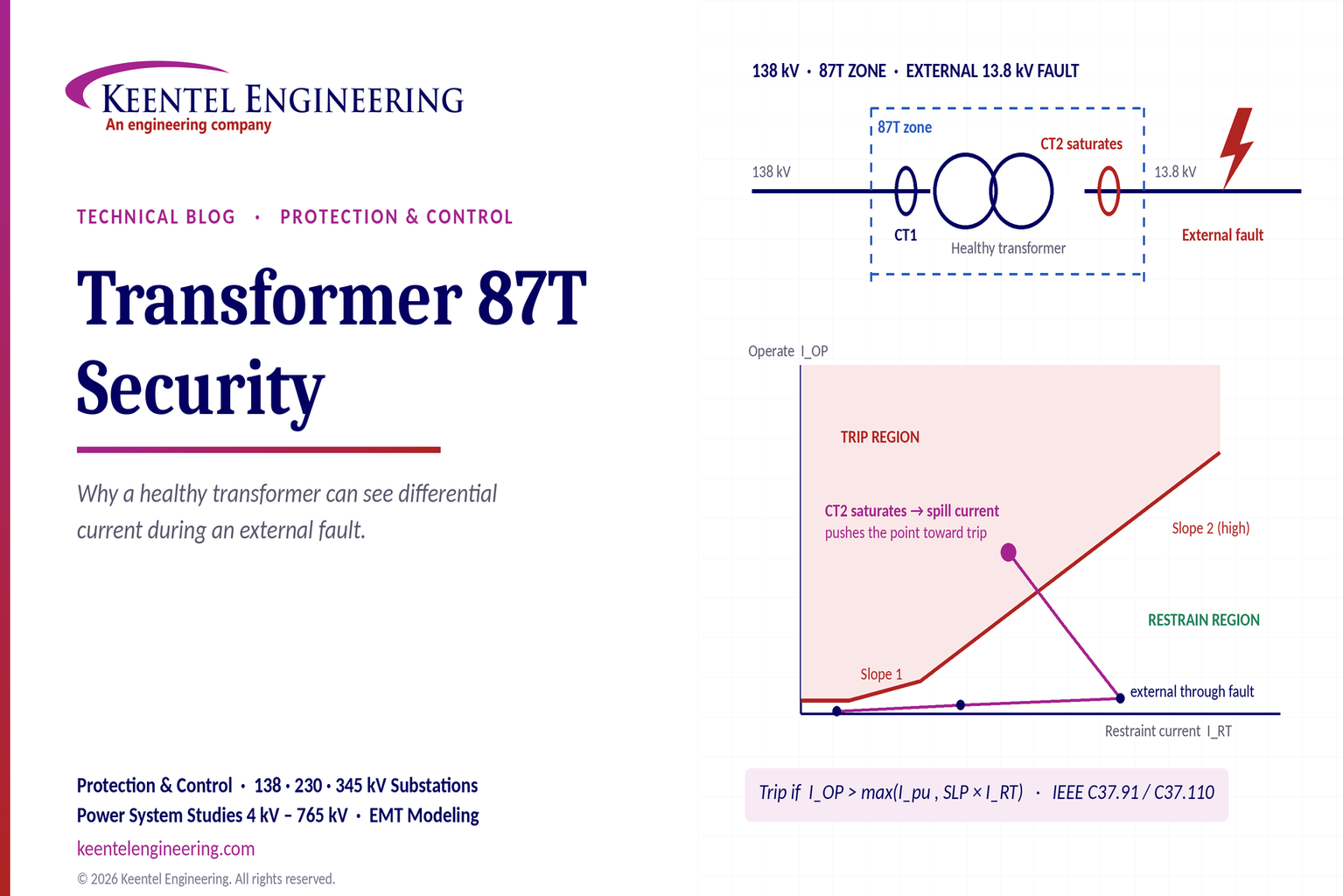
Learn why transformer differential relays detect current during external faults, how CT saturation causes spill current, and how secure 87T protection prevents trips.
By SANDIP R PATEL
•
October 10, 2026
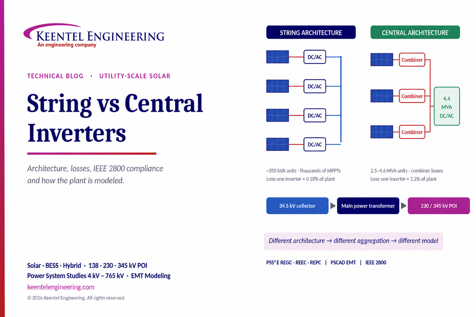
Compare string vs central inverters for utility-scale solar, including efficiency, maintenance, grid compliance, reactive power and interconnection studies.
By SANDIP R PATEL
•
October 9, 2026
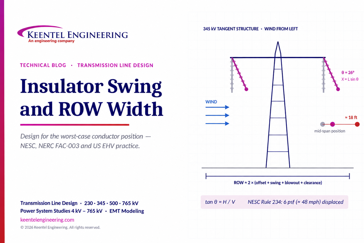
Learn how insulator swing angle and conductor blowout affect transmission line ROW width, with NESC clearances, NERC FAC-003 guidance, and a 345 kV example.
Copy

By SANDIP R PATEL
•
October 3, 2026
Engineering guide to PRC-028 disturbance recording, PRC-029 ride-through and PRC-030 event detection for inverter-based resources.

By SANDIP R PATEL
•
October 3, 2026
A practical guide to SSO classification, SSR, PEDI, Wind-SSCI, EMT analysis, mitigation and protection based on CIGRE TB 909.





