
A Coordinated Electric System Interconnection Review—the utility’s deep-dive on technical and cost impacts of your project.
Challenge: Frequent false tripping using conventional electromechanical relays
Solution: SEL-487E integration with multi-terminal differential protection and dynamic inrush restraint
Result: 90% reduction in false trips, saving over $250,000 in downtime
ERCOT enforces all of the above through simulation, which means your model is your compliance case. The bar is now high:
- Whole-facility scope. The model must represent everything the IT load, the UPS and power conversion, the cooling plant, the protection and control systems in formats compatible with ERCOT's study platforms (PSS/E, PSCAD, TSAT).
- Real control loops, not approximations. Generic textbook representations are unacceptable. The model must capture the actual inner control behavior of your power electronics.
- Hardware-validated converter models. For electronic loads, the PSCAD model must be benchmarked against actual hardware testing including voltage ride-through and subsynchronous response. A model assembled from standard PSCAD library blocks fails by definition, because a generic block has never been tested against your vendor's hardware. The good news: validation is a hardware-type test, so results for a given converter product are reusable across every facility that uses it.
- Format migration. Facilities that previously submitted the older composite load model (CMLD) format must transition to EPRI's PERC1 format.
- Three checkpoints. Models are reviewed before the stability study begins (no model, no study), before each quarterly stability assessment, and for electronic loads one final time before energization, when you must submit as-built models with a documented comparison against the previously studied data and a sworn attestation that the model matches actual field settings. ERCOT's review takes 10 business days, extendable by 20 put it on your critical path.
- A living obligation. Change your technology, controls, or relay settings in a way that affects ride-through including converting a crypto mining site to an AI data center — and you've triggered a new interconnection study, even if your megawatts don't change.
| Parameter | Detail |
|---|---|
| System | 230 kV / 138 kV transmission corridors, wind and wet-snow icing exposure |
| Data basis | 15 years of minute-resolution forced-outage records + regional weather observations |
| Core methods | Event grouping, MVA performance curves, time-to-95%-restore, area outage rate curves, fragility modeling, rerun-history benefits, exceedance and log-domain risk metrics |
| Headline result | ≈85% of maximum resilience benefit at 60% of original capital; worst-event restoration window cut from 11 days to 5 in rerun-history terms |
| Decision supported | Capital portfolio selection; resilience plan filing; post-investment verification framework |
| System / Topic | Governing Standard(s) | What It Controls |
|---|---|---|
| Overall plant electrical distribution | IEEE 141 (Red Book); IEEE 666 | Distribution architecture, voltage selection, design of generating station auxiliary service systems |
| Power system studies | IEEE 399 (Brown Book); IEEE 551 | Load flow, symmetrical/asymmetrical short circuit, motor starting methodologies down to the lowest LV panelboard |
| Protection & coordination | IEEE 242 (Buff Book); IEEE 3004.5; IEEE C37 series | Generator relaying (21, 59N, 87G), time-current coordination, selective clearing between LV and MV tiers |
| GSU / UAT / SST transformers | IEEE C57.12.00 and C57 family | Transformer ratings, impedance, testing, loading |
| HV switchyard breakers | IEEE C37.06 | AC high-voltage circuit breaker preferred ratings |
| MV switchgear (13.8 kV) | IEEE C37.20.2; IEEE C37.20.7 | Metal-clad construction, compartmentalization, vacuum breakers; arc-resistant design with plenum venting |
| MV cable | UL 1072; ICEA S-93-639 (NEMA WC 74) | Type MV-105 shielded cable, 133% insulation level for HRG systems |
| LV switchgear (480 V) | IEEE C37.13; UL 1558 | Metal-enclosed LV power circuit breaker switchgear to 635 V, draw-out ACBs with electronic trip units |
| Motor control centers | UL 845; NEMA ICS 18 | LV-MCC construction, MCCB/MCP protection for motors under ~200 HP |
| Motors | NEMA MG-1 | Motor performance, starting characteristics, service factors |
| DC & battery systems | IEEE 485; IEEE 946 | Lead-acid battery sizing (125/250 VDC), DC auxiliary system design |
| Grounding | IEEE 80; IEEE 142 (Green Book) | Ground grid step/touch potential limits; system grounding including high-resistance grounding |
| Lightning protection | IEEE 998 | Direct-stroke shielding of switchyard and outdoor generator structures |
| Arc flash & electrical safety | IEEE 1584; NFPA 70E | Incident energy calculation; worker safety boundaries and PPE |
| Fire protection | NFPA 850 | Fire protection and risk management for combustion turbine generating plants |
| Installation code | NEC (NFPA 70); NESC | Wiring methods inside the plant fence; overhead/outdoor clearances at the switchyard |
| Interconnection & compliance | FERC LGIP; NERC MOD-025/026/027, PRC-019/024/029, FAC-008 | Interconnection process, model validation, protection/ride-through coordination, facility ratings |
| IFC / Construction Deliverable | Purpose |
|---|---|
| Stamped IFC packages | Legal basis for construction; P.E. responsible charge |
| Final relay settings & TCCs | Protection as-installed matches the coordination study |
| Calculation archive | Owner records; NERC audit evidence trail |
| Commissioning procedures | Safe, sequenced energization; MOD field testing |
| Construction support | RFIs, field changes, FAT/SAT witness |
| As-builts & model handoff | Operating baseline; future study currency |
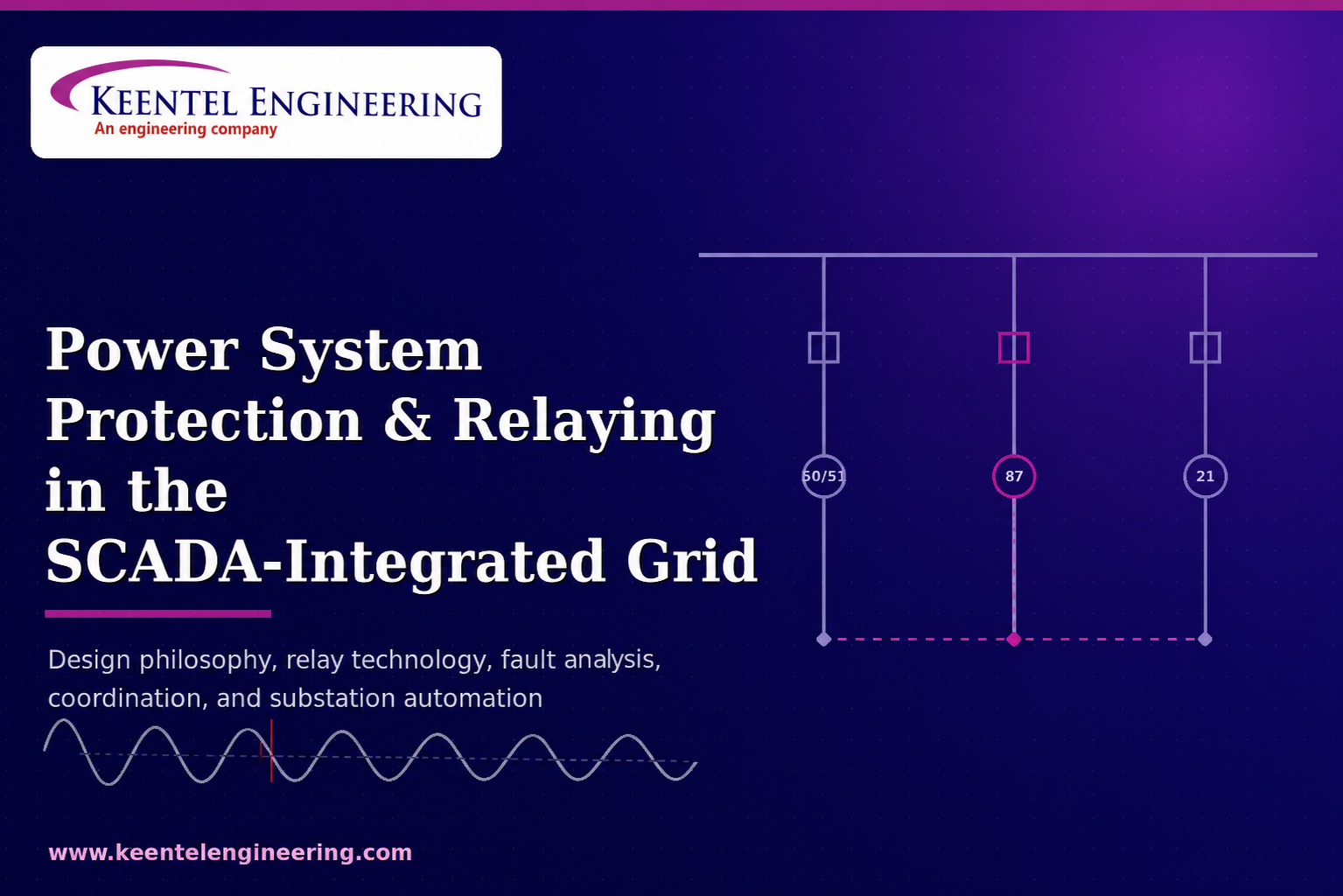
POWER SYSTEM PROTECTION AND RELAYING IN THE SCADA-INTEGRATED GRID
Jul 11, 2026 | Blog
Design Philosophy, Relay Technology, Fault Analysis, Coordination, and Substation Automation
Executive Overview
This content package presents Keentel Engineering's integrated perspective on power system protection and relaying design in the era of the SCADA-integrated, digitally instrumented grid. It is organized in three parts: a long-form technical blog covering the complete protection design chain — from protection philosophy and instrument transformer specification through relay technology selection, fault analysis, overcurrent and distance coordination, equipment-specific protection schemes, high-impedance fault detection, grounding, and substation SCADA/communications architecture; a practitioner-oriented FAQ addressing the questions asset owners, developers, and plant engineers most frequently raise; and three anonymized case studies demonstrating how this integrated approach performs on real project archetypes: a utility-scale solar-plus-storage interconnection, an industrial relay modernization, and a distribution utility's wildfire-driven ground-fault protection program.
The unifying thesis: protection design decisions are coupled — to the short-circuit model, to the grounding design, to the communications and SCADA architecture, to interconnection ride-through obligations, and to the NERC compliance program that must defend all of it. Engineering these as one configuration-controlled scope, rather than fragmented procurements, is the difference between a system that merely has relays and a system that is demonstrably protected, observable, and audit-ready.
Technical Blog: Designing Power System Protection and Relaying for the SCADA-Integrated Grid
Protection engineering has one uncompromising mandate: detect an abnormal condition on the power system and isolate it in milliseconds, automatically, with the smallest possible portion of the network removed from service. Supervisory Control and Data Acquisition (SCADA) engineering has a complementary mandate: give operators real-time visibility and remote control over every breaker, relay, and measurement point in the system. For decades these two disciplines were designed by different teams, procured under different budgets, and commissioned on different schedules. That separation is no longer tenable. Modern numerical relays are simultaneously protection devices, fault recorders, revenue-grade meters, and SCADA data concentrators. A protection scheme that is not designed from day one as an integrated protection-and-SCADA architecture leaves reliability, compliance, and operational value on the table.
At Keentel Engineering, we design protection and relaying systems for utility substations, transmission lines, utility-scale renewable and BESS facilities, industrial plants, and large-load interconnections — and we treat the SCADA and communications layer as a first-order design input, exactly as we treat grid interconnection requirements. This article walks through the complete design chain: protection philosophy, instrument transformers, relay technology selection, fault analysis, coordination, equipment-specific schemes, high-impedance fault detection, grounding, and the SCADA architecture that binds it all together.
1. The Protection Design Philosophy: Five Properties in Tension
Every protection decision is a negotiated settlement among five properties. Reliability (dependability) demands the relay always operates for faults in its zone. Security demands it never operates when it should not. Selectivity demands that only the breaker(s) nearest the fault open, preserving service to the rest of the network. Speed demands fault clearing fast enough to protect equipment thermally and mechanically and to preserve transient stability. Sensitivity demands detection of the minimum credible fault — including high-impedance ground faults that may draw less current than normal load.
These properties conflict. Faster tripping erodes security margin. Higher sensitivity increases exposure to misoperation on load transients, inrush, and CT error. The protection engineer's job is not to maximize any single property but to document, for each zone, the deliberate trade-offs — and then to prove them with fault studies, coordination studies, and relay test plans. Systems are divided into overlapping zones of protection — generator, bus, transformer, transmission line, feeder, motor — with each zone bounded by circuit breakers and each relay assigned a primary zone plus remote or local backup duty. Overlap is achieved by lapping CT locations around breakers so that no point on the system is unprotected, and every primary scheme has a defined backup that operates with an intentional coordination delay if the primary fails.
Keentel design standard
Every protection single-line we issue carries a zone diagram with explicit CT overlap at each breaker, a primary/backup assignment matrix, and a documented fault-clearing time budget (relay operate time + breaker interrupting time + margin) checked against equipment withstand and stability limits.
2. Instrument Transformers: Where Every Protection Error Begins
Relays never see the primary system. They see the secondary output of current transformers (CTs) and voltage transformers (VTs or CVTs), and every error those transducers introduce propagates directly into relay reach, coordination margins, and differential stability. CT specification is therefore the first real engineering decision in any protection design.
2.1 Current transformer selection and saturation
A protection-class CT must reproduce fault current — including the fully offset asymmetrical waveform with DC component — without saturating before the relay makes its decision. The governing check is the CT's knee-point or accuracy-limit voltage against the voltage demanded by the maximum fault current flowing through the total secondary burden (relay input, lead resistance both ways, and CT winding resistance). Remanent flux from a prior fault clearance and the X/R-driven DC offset can multiply the effective flux demand several-fold; a CT that is marginally adequate for symmetrical current will saturate badly on an offset waveform, distorting the secondary current, delaying instantaneous elements, and destabilizing differential schemes through unequal saturation of paired CTs.
Our practice is to size protection CTs with explicit transient dimensioning: compute maximum through-fault current at the CT location from the short-circuit study, apply the system X/R ratio, include realistic lead burden from the physical cable schedule, and verify against the CT excitation curve or IEC/IEEE accuracy class rating. Metering-class accuracy and protection-class transient performance are different problems — a CT core optimized for 0.3-class revenue accuracy at load current is designed to saturate early, which is precisely what a protection core must not do. Dual-core or multi-ratio CTs resolve the conflict.
2.2 Voltage transformers and CVT transients
Magnetic (wound) VTs give faithful reproduction across the protection bandwidth and are standard at distribution and lower transmission voltages. At EHV, capacitive voltage transformers (CVTs) dominate on cost — but their tuned capacitive divider and compensating reactor produce a transient response of their own. When primary voltage collapses during a close-in fault, the CVT's stored energy discharges into the secondary as a decaying transient that can momentarily misrepresent the voltage magnitude and phase the distance relay uses to compute impedance. High-speed distance elements must therefore include CVT transient logic or accept a small intentional delay for close-in, low-voltage faults. This is a classic example of a component-level characteristic that becomes a scheme-level setting decision.
3. From Electromechanical to Numerical: Choosing Relay Technology Deliberately
Four generations of relay technology remain in service across North American systems, and a large fraction of our relay modernization work involves migrating among them without breaking coordination with neighbors that have not migrated.
| Generation | Operating principle | Strengths | Design limitations |
|---|---|---|---|
| Electromechanical | Induction disc/cup, attracted armature; torque from flux interaction | Proven, immune to firmware defects, inherent inverse-time character | Fixed characteristic, drift with age, high burden, no event records, single function per case |
| Solid-state (static) | Analog comparators, op-amp circuits replicating disc characteristics | Faster reset, lower burden, more compact panels | Component aging, limited flexibility, still one function per unit, minimal diagnostics |
| Digital | Sampled waveforms, microprocessor computes operating quantities | Multiple curves/functions, self-supervision, basic event recording | Early platforms limited in sampling rate, memory, and communications |
| Numerical (IED) | High-rate synchronized sampling, DSP filtering, phasor estimation, programmable logic | Dozens of ANSI functions in one device, oscillography, metering, IEC 61850/DNP3 comms, synchrophasors | Firmware management, cybersecurity obligations, settings complexity, testing discipline required |
The numerical intelligent electronic device (IED) is not just a faster relay — it is the physical point where the protection system and the SCADA system merge. A single modern IED provides the protection elements, the disturbance recorder, the sequence-of-events log time-stamped to the microsecond via IRIG-B or PTP, the local metering the RTU used to require dedicated transducers for, and the communications interface that carries all of it to the control center. Designing the protection scheme and the SCADA points list as one exercise eliminates redundant hardware, wiring, and commissioning effort — and it is why we insist on a unified points list, protocol map, and network architecture drawing in every substation design package we deliver.
The self-supervision capability of numerical relays deserves particular emphasis. An electromechanical relay that fails does so silently — the failure is discovered when the relay fails to trip, which is the worst possible moment. A numerical IED continuously monitors its own power supply, memory, analog acquisition chain, and trip-coil continuity, and reports a failure to SCADA within seconds. This converts hidden protection failures from a statistical reliability risk into an ordinary maintenance work order, and it is the technical foundation for condition-based relay maintenance programs accepted under NERC PRC-005.
4. Fault Analysis: The Quantitative Foundation
No relay setting is defensible without a fault study. The short-circuit analysis establishes, for every relay location, the maximum fault duty (which sets breaker interrupting ratings, CT dimensioning, and instantaneous element security) and the minimum fault current (which sets sensitivity requirements and proves that the relay will actually see the faults it is assigned to clear).
4.1 Balanced and unbalanced faults
The three-phase bolted fault is the classical balanced case and usually — though not always — the maximum-current condition. The overwhelming majority of real faults, however, are unbalanced: single line-to-ground faults dominate on overhead systems, followed by line-to-line and double line-to-ground events. Unbalanced conditions are analyzed with symmetrical components, which decompose any unbalanced set of three-phase phasors into positive-, negative-, and zero-sequence sets. Each sequence network has its own impedance model of the system, and each fault type corresponds to a specific interconnection of those networks: the single line-to-ground fault places all three networks in series through three times the fault resistance; the line-to-line fault connects positive and negative networks in parallel; the double line-to-ground fault parallels all three.
Sequence quantities are more than an analysis convenience — they are directly measurable operating quantities inside numerical relays. Negative-sequence current is a sensitive, load-independent indicator of unbalance used for generator rotor thermal protection (ANSI 46), for directional polarization, and for sensitive unbalanced-fault elements. Zero-sequence (residual) current exists only when ground is involved, which makes it the natural operating quantity for ground overcurrent (51N/51G) and restricted earth fault schemes. Transformer winding connections manipulate these quantities deliberately: a delta winding blocks zero-sequence current from passing through, creating a ground-source boundary, and a delta–wye transformation imposes a phase shift on positive- and negative-sequence quantities that every differential scheme across that transformer must compensate.
4.2 The DC offset and machine transients
Fault current is not a clean sinusoid. The instant of fault inception relative to the voltage wave superimposes a decaying DC component governed by the system X/R ratio, and contributions from nearby synchronous machines decay through subtransient and transient regimes as machine flux redistributes. Practical consequences: breakers must be rated for asymmetrical interrupting duty; instantaneous elements must be set with security margin against the offset peak; CTs must be dimensioned for the offset waveform; and time-overcurrent coordination must be checked at the current levels that actually persist beyond the subtransient window, not just the flashy first-cycle numbers.
Why this matters commercially
Interconnection studies, arc-flash studies, breaker duty assessments, and relay settings all consume the same short-circuit model. Building that model once, correctly, under configuration control — and keeping it synchronized with the as-built system — is one of the highest-leverage engineering investments an asset owner can make. Keentel builds and maintains these models in the owner's preferred platform and ties every relay setting file to a specific model revision.
5. Overcurrent Protection and Coordination: The Discipline of Time and Current
Overcurrent protection remains the workhorse of distribution and industrial systems and the universal backup on transmission. Its elements are simple — a pickup threshold and a time characteristic — but coordinating dozens of them across a network so that every fault is cleared by the nearest device first, with backup always waiting behind it, is a genuinely difficult combinatorial problem.
5.1 Characteristic families and their physics
Inverse-definite-minimum-time (IDMT) characteristics operate faster as current increases, mirroring the thermal damage curves of the equipment they protect. The standard families — standard/moderately inverse, very inverse, and extremely inverse — differ in how steeply operating time falls with current. Extremely inverse curves approximate fuse and conductor damage characteristics and coordinate naturally with downstream fuses and reclosers on distribution feeders; very inverse curves suit systems where fault current falls off significantly with distance from the source; definite-time elements suit locations where fault current barely changes across the protected zone, such as systems with strong sources or short feeders. Pickup is set above maximum load with margin for cold-load pickup and transformer inrush, yet below minimum fault current with a dependable sensitivity margin; the time-dial (time multiplier) setting then positions each curve relative to its neighbors.
5.2 Coordination method
Discrimination can be achieved by current alone (where impedance between devices creates distinct fault levels), by time alone (fixed grading steps regardless of fault level), or — the standard modern practice — by both, using inverse-time curves graded with a coordination time interval (CTI). The CTI budget between a downstream and upstream device typically comprises breaker interrupting time, relay overtravel or reset allowance, CT and relay tolerance, and a safety margin; with numerical relays and modern breakers this commonly totals on the order of 0.2–0.3 seconds, versus 0.3–0.4 seconds in legacy electromechanical practice. Tightening CTI through relay modernization is often the single cheapest way to reduce arc-flash incident energy deep in an industrial system, because every upstream grading step compounds the clearing time at the worst-case bus.
5.3 Directional supervision
Wherever fault current can flow through a relay location in both directions — parallel feeders, ring buses, looped distribution, and any system with distributed generation — plain overcurrent elements cannot discriminate and must be supervised by directional elements (ANSI 67). Directional decision requires a polarizing quantity, classically the fault-loop voltage with a characteristic angle chosen for the system X/R, or negative- and zero-sequence quantities for ground directionality. The proliferation of inverter-based resources complicates this: inverters contribute limited fault current (often 1.1–1.5 per unit of rating) with unconventional sequence content, weakening both the pickup sensitivity and the polarizing signals traditional schemes rely on. Protection design for renewable-heavy networks must verify directional dependability against the actual inverter fault-current behavior documented in the manufacturer's EMT model — a direct link between interconnection modeling and protection settings that we routinely close for our clients.
6. Transmission Line Protection: Distance and Differential
6.1 Distance protection zones
Distance relays compute the apparent impedance from measured voltage and current; because line impedance is proportional to length, impedance is a proxy for fault position that is largely independent of source strength. The classical characteristics — plain impedance (a circle centered at the origin), reactance (a horizontal line, insensitive to arc resistance), and mho (a circle through the origin, inherently directional and load-tolerant) — remain the conceptual vocabulary, with modern numerical relays offering quadrilateral characteristics that combine reactance-like arc-resistance coverage with explicit resistive blinders for load encroachment security.
Standard zone philosophy: Zone 1 is set to underreach the remote terminal — commonly 80–85% of positive-sequence line impedance — and trips instantaneously; the deliberate underreach absorbs CT/VT error, line impedance uncertainty, and CVT transients so that Zone 1 can never overreach for a fault beyond the remote bus. Zone 2 overreaches the remote terminal (typically 120–150% of the line, checked against the shortest adjacent line) with a coordination delay on the order of 0.25–0.4 seconds, covering the last 15–20% of the line plus remote bus faults. Zone 3, where applied, provides remote backup with a longer delay and must be checked rigorously against maximum load encroachment — the misapplication of Zone 3 under heavy, depressed-voltage loading was a contributing mechanism in major blackout events and is the origin of today's NERC loadability requirements (PRC-023).
6.2 Pilot schemes and line current differential
Stepped-distance protection alone leaves the middle of every line dependent on a delayed zone for one terminal. Pilot (teleprotection) schemes close that gap by exchanging logic over a communications channel: permissive overreach transfer trip (POTT) requires both terminals' overreaching elements to agree; directional comparison blocking (DCB) trips unless the remote terminal declares the fault external; direct transfer trip (DTT) commands the remote breaker open for conditions the remote relays cannot see, such as transformer faults behind a line with no local breaker. Channel technology has migrated from power-line carrier and audio tones to SONET/SDH and MPLS-TP packet networks and dedicated fiber, which brings channel monitoring and deterministic latency into the protection engineer's scope.
Where dedicated fiber exists end-to-end, line current differential (87L) is the premier scheme: it compares actual current phasors between terminals, is inherently selective for the entire line with no reach settings to coordinate, tolerates weak infeed and series compensation better than distance elements, and is largely immune to power swings and load encroachment. Its engineering burden shifts to the communications layer — channel asymmetry and latency must be measured and compensated, and GPS/PTP time alignment or ping-pong synchronization must be engineered and monitored through SCADA.
7. Equipment Protection: Transformers, Generators, Motors, and Buses
7.1 Transformer protection (87T and companions)
Percentage-restrained differential protection is the primary electrical scheme for power transformers above roughly 5–10 MVA. The operating principle — the vector sum of currents entering the zone should be zero — is complicated in transformers by ratio mismatch, on-load tap changer excursion, winding phase shift, and zero-sequence discontinuity, all of which numerical relays now compensate internally through settings rather than through auxiliary CT gymnastics. The restraint slope (commonly a dual-slope characteristic beginning around 20–40%) provides security against CT error that grows with through-current, with the second, steeper slope guarding against CT saturation on heavy external faults.
Magnetizing inrush is the defining security challenge: energizing a transformer draws an offset, harmonic-rich current on one side of the differential zone only, mimicking an internal fault. Inrush current is distinguished by its harmonic signature — a pronounced second-harmonic component — and by its waveform shape, so differential elements employ second-harmonic restraint or blocking (typical thresholds in the 15–20% range) and, in modern relays, waveform-gap recognition. Fifth-harmonic restraint similarly secures the element against overexcitation, which produces genuine excitation current the differential must tolerate while the volts-per-hertz element (24) takes coordinated action. Sympathetic inrush — offset flux driven in an already-energized transformer when a neighbor is switched — must also be reviewed anywhere transformers share a bus.
The electrical schemes are complemented by restricted earth fault protection (REF/87N, a sensitive zero-sequence differential covering the wye winding near the neutral where phase differential sensitivity collapses), by mechanical devices — the Buchholz gas-and-surge relay on conservator units, sudden-pressure relays on sealed units — and by thermal supervision of oil and winding temperature with staged alarm, cooling, and trip outputs. Every one of these devices is also a SCADA point: gas accumulation alarms, tap position, cooling stage status, and top-oil temperature trends feed the condition-monitoring dashboard that turns transformer protection into transformer asset management.
7.2 Generator protection
Generators accumulate the most demanding and most diverse protection portfolio of any single asset because their failure modes span electrical, thermal, and mechanical physics. The core electrical scheme is high-security phase differential (87G), backed by voltage-restrained or voltage-controlled overcurrent (51V) for system backup. Stator ground protection depends on the grounding method: high-impedance-grounded machines typically use fundamental neutral overvoltage (59N/64G) covering roughly 90–95% of the winding, extended to 100% coverage by third-harmonic differential methods or subharmonic injection so that faults near the neutral — invisible to fundamental schemes — are still detected. Rotor field grounds are detected by injection-based 64F schemes; the first ground is an alarm, but a second ground short-circuits part of the field, unbalances rotor flux and forces, and can be catastrophic, so tripping philosophy for the first ground must be an explicit owner decision.
The abnormal-operating-condition suite is equally important: loss-of-excitation (40, impedance elements watching the machine slide toward the steady-state stability limit), negative-sequence thermal duty (46, protecting the rotor surface against unbalance-induced heating per the machine's I2²t withstand), reverse power (32, anti-motoring for prime-mover protection), over/underfrequency (81O/U), volts-per-hertz overexcitation (24), inadvertent energization logic (50/27), and out-of-step (78). For synchronous machines connected to networks now governed by ride-through standards, every one of these elements must be checked against the required voltage and frequency ride-through envelopes so that protection does not trip the machine for conditions the interconnection agreement obligates it to survive — a coordination task between protection settings and NERC PRC-024/PRC-029-family compliance that we perform as a single integrated study.
7.3 Motor and busbar protection
Large motor protection is thermal-model protection first: the relay integrates a thermal replica (49) fed by stator current, tracks starting duty against the machine's hot and cold safe-stall limits, counts starts per hour, and supervises locked-rotor conditions (48/51LR) where the distinction between a prolonged start and a stalled rotor may require a speed switch. Instantaneous phase (50) and sensitive ground (50G on a core-balance CT) elements handle faults; undervoltage (27) and phase reversal/unbalance (46/47) elements handle supply-quality events that convert into rotor heating.
Busbar faults are rare but carry the highest fault energy and the widest outage footprint in the station, so bus protection prioritizes speed with extreme security. Low-impedance percentage differential schemes with per-terminal CT saturation detection are today's standard for complex, reconfigurable buses, with dynamic zone assignment following disconnector position; high-impedance differential remains a superbly secure and simple choice where CT ratios are uniform and dedicated cores are available. Breaker-failure protection (50BF) completes the station scheme: if a tripped breaker fails to interrupt within its timer window, 50BF trips the surrounding zone — and its correct, selective operation depends on accurate breaker status and initiate signals that are themselves part of the station's wiring-and-communications design.
8. High-Impedance Faults: The Detection Problem Conventional Relaying Cannot See
A downed conductor lying on asphalt, dry sand, or gravel may draw only a few amperes to a few tens of amperes — far below feeder load, entirely invisible to overcurrent pickup, yet lethal to the public and a proven wildfire ignition mechanism. High-impedance fault (HIF) detection is therefore not an equipment-protection problem but a public-safety problem, and it demands fundamentally different signal processing.
HIF current is distinguished by signatures rather than magnitude: randomness and intermittency from arc extinction and re-strike, rich low-order and interharmonic content, cyclic asymmetry between half-cycles, and slow growth as the arc conditions the contact surface. Detection algorithms extract features — harmonic energy trajectories, wavelet coefficients, randomness metrics — and classify them against learned load behavior, trading detection probability against nuisance-alarm rate. Modern feeder relays ship with embedded HIF elements built on exactly this architecture, and utilities in wildfire-exposed territory increasingly pair them with downed-conductor logic, falling-conductor open-phase detection using synchrophasor or fast communications schemes, and REFCL/resonant-grounding strategies at the substation. Because HIF outputs are probabilistic, their disposition — alarm to SCADA for operator action versus automatic trip — is a policy decision each utility must make deliberately, and the SCADA alarm architecture must present these events with the context operators need to act within minutes.
9. System Grounding and the Ground Grid: The Silent Half of Protection Design
The system-neutral grounding method determines the entire character of ground-fault protection. Solidly grounded systems deliver high ground-fault current — easy to detect, harsh on equipment, and demanding on arc-flash energy. Low-resistance grounding (commonly a few hundred amperes) caps damage at the fault point while preserving straightforward selective relaying, and is the default for industrial medium-voltage systems. High-resistance grounding limits the first ground fault to a few amperes, permitting continued operation with alarm — invaluable for continuous processes — at the cost of pinpointing-and-locating discipline and careful insulation coordination for the sustained phase-to-phase voltage on the unfaulted phases. Ungrounded and resonant-grounded (Petersen coil) systems suppress fault current further still and, in the resonant case, actively extinguish arcing ground faults, which is why compensated grounding is central to several utilities' wildfire-mitigation programs; both demand sensitive wattmetric or admittance-based ground relaying because there is almost no zero-sequence current to measure.
Beneath every substation, the ground grid design closes the personnel-safety loop: grid resistance, ground potential rise, and touch and step voltages during the maximum ground fault must satisfy IEEE Std 80 tolerable-body-current criteria, which depend on soil resistivity structure measured in the field (Wenner four-pin traverses resolved into multi-layer soil models), fault-current split between the grid and overhead ground wires or cable sheaths, and fault-clearing time — which is set by the protection engineer. This is a genuinely coupled design problem: faster protection directly reduces the tolerable-voltage burden on the grid, and grid design assumptions must be revisited whenever a protection upgrade changes clearing times or system changes raise fault duty. Keentel performs grounding studies (including WinIGS-based grid modeling),
protection studies and short-circuit studies as one coordinated package for precisely this reason.
10. The SCADA Architecture: Turning Protection Into an Observable, Operable System
10.1 The four layers
A substation SCADA architecture resolves into four layers. Field instrumentation — the CTs, VTs, transducers, temperature probes, gas monitors, and breaker auxiliary contacts that originate every measurement and status. Data concentration and control — RTUs, PLCs, and increasingly the protection IEDs themselves, which acquire, time-stamp, and execute control.
Communications — the serial and Ethernet networks, protocols, and wide-area links that move data with the required latency, integrity, and availability. And the master layer — SCADA host/HMI, historian, alarm management, and the EMS/ADMS applications that convert telemetry into operating decisions. The historical distinction between the 'dumb telemetry' RTU and the logic-bearing PLC has effectively dissolved; modern platforms do both, and in a protection-centric substation the IEDs carry most of the acquisition burden, with the RTU or data concentrator serving as protocol gateway and point-of-demarcation to the control center.
10.2 Protocols and the IEC 61850 substation
DNP3 remains the dominant master-station protocol in North America, prized for its report-by-exception efficiency, time-stamped event buffering, and — in secure-authentication variants — cryptographic protection of control operations. Inside the substation fence, IEC 61850 changes the design language itself: devices publish self-describing logical nodes; GOOSE messaging replaces hardwired inter-relay trip, block, and interlock wiring with sub-4-millisecond peer-to-peer Ethernet messages; and Sampled Values streams from merging units allow process-bus architectures in which copper CT/VT wiring to every relay is replaced by fiber. The engineering payoff is enormous — interlocking and breaker-failure initiate schemes become configuration rather than construction — but it moves network engineering (VLANs, redundancy protocols such as PRP/HSR, time synchronization via PTP) squarely into the protection engineer's deliverables, and it makes the SCD configuration file a controlled engineering document on par with the relay settings files.
10.3 What SCADA integration returns to protection
- Event analysis — Every relay operation arrives with a synchronized sequence-of-events record and oscillography, collapsing post-fault analysis from days of site visits to minutes at a desk.
- Asset health — Relay self-supervision alarms, trip-circuit monitoring, breaker operation counters, and DC system telemetry convert hidden failures into scheduled work — the backbone of a PRC-005-compliant, condition-based maintenance program.
- Operational flexibility — Settings group changes can be supervised remotely for planned abnormal topologies; adaptive schemes can respond to DER output, seasonal load, or storm posture.
- Restoration speed — Fault-location estimates from relays, delivered through SCADA, dispatch crews to the right structure instead of the right circuit.
- Compliance — Disturbance records and misoperation data organize evidence for NERC PRC-004 misoperation review and PRC-002 disturbance-monitoring obligations.
10.4 Cybersecurity as a protection-reliability requirement
Every communications path that makes protection observable also makes it attackable. A SCADA-integrated protection design must therefore carry a security architecture: network segmentation with an explicit electronic security perimeter, role-based access and centralized authentication for relay engineering access, secure protocol variants for control, logging and monitoring of engineering-access sessions, firmware and settings configuration management, and disciplined handling of transient devices such as test laptops. For BES facilities these are NERC CIP obligations with audit consequences; for every facility they are simply sound engineering. Our design packages treat the security architecture drawing set with the same rigor as the AC/DC schematics — because a protection scheme whose settings can be silently altered is not a protection scheme.
11. The Keentel Perspective: Protection, SCADA, and Interconnection as One Design
The thread running through every section above is that protection design decisions are coupled — to the fault study, to the grounding design, to the communications architecture, to interconnection ride-through obligations, and to the compliance program that must defend all of it in an audit. Treating these as separate scopes procured from separate vendors is how systems accumulate miscoordination, hidden failure modes, and compliance findings. Keentel Engineering's practice is built on the opposite premise: the short-circuit model, the protection and coordination study, the relay settings and logic, the grounding study, the SCADA points list and network design, and the NERC compliance evidence are one integrated engineering product, developed under one configuration-control discipline, from the 30% design milestone through commissioning and into operations support.
Whether the asset is a transmission substation, a utility-scale solar or BESS plant working through its interconnection requirements, a data center campus negotiating large-load protection requirements, or an industrial system overdue for relay modernization, the design questions in this article are the ones we answer every day — quantitatively, with studies and settings files, not with generalities.
Case Studies
The following case studies are drawn from representative Keentel Engineering project experience. All client names, project names, locations, and identifying details have been anonymized or generalized; technical parameters have been rounded or adjusted where necessary to preserve confidentiality while retaining engineering fidelity.
Case Study 1: Protection and SCADA Integration for a Utility-Scale Solar-Plus-Storage Collector Substation
Background
An independent power producer was developing a utility-scale photovoltaic facility of approximately 200 MW, co-located with a four-hour battery energy storage system, interconnecting to a transmission utility at 230 kV through a new collector substation. The interconnection agreement imposed the transmission owner's full protection, telemetry, and disturbance-monitoring requirements at the point of interconnection, including redundant line protection on the gen-tie, remote terminal upgrades at the utility's end, and ride-through obligations that constrained every protective setting in the plant. The EPC schedule allowed no float between substation energization and back-feed for commissioning of the inverter blocks.
The Challenge
- The gen-tie line was electrically short, making conventional stepped-distance Zone 1 reach margins unacceptable — CT/VT error and line-impedance uncertainty consumed most of the underreach allowance.
- The plant's fault contribution was almost entirely inverter-based: roughly 1.2 per unit of aggregate inverter rating, with manufacturer-controlled negative-sequence behavior. Utility-side protection assumptions about infeed, and plant-side directional and sensitivity checks, both had to be validated against the certified EMT model rather than classical machine assumptions.
- The transmission owner required protection settings that were demonstrably coordinated with mandated frequency and voltage ride-through envelopes — any plant protection element capable of tripping inside the ride-through region required written technical justification.
- The owner's operations group required full visibility of the collector system — feeder relays, transformer protection, BESS interfaces, meteorological and plant-controller data — in both their own operations center and the transmission operator's EMS, over different protocols.
Keentel's Approach
Keentel served as protection and SCADA engineer of record for the collector substation and gen-tie, working from the same EMT and short-circuit models used in the interconnection studies — eliminating the model handoff gap that typically separates interconnection compliance from protection design.
- Specified redundant line current differential (87L) over diverse fiber paths as primary gen-tie protection, with quadrilateral distance and directional ground overcurrent backup; POTT logic over the secondary channel provided a communications-degraded fallback. Reach and timing settings were validated against inverter fault-current signatures from the EMT model, not classical source assumptions.
- Designed the 230/34.5 kV main power transformer protection with dual-slope percentage differential, second- and fifth-harmonic security, restricted earth fault on the wye winding, and sudden-pressure and thermal devices fully mapped into SCADA.
- Engineered collector feeder protection with sensitivity checks at minimum inverter output, verifying that end-of-feeder faults remained detectable when the plant's fault contribution was at its floor — a check that failed under the vendor's template settings and required pickup revisions on three feeders.
- Produced a protection-versus-ride-through coordination document mapping every plant protective element against the required voltage and frequency withstand envelopes, providing the transmission owner a single auditable artifact and accelerating their settings approval cycle.
- Implemented IEC 61850 inside the substation — GOOSE for breaker failure initiate, transformer lockout distribution, and feeder interlocking on a PRP-redundant LAN — with a station gateway presenting DNP3 to both the owner's SCADA and the transmission operator's EMS from a single points database, and PTP-disciplined time synchronization for sequence-of-events alignment.
Results
| Metric | Outcome |
|---|---|
| Settings approval | Transmission owner approved protection settings on first formal submission; the ride-through coordination document was cited as the basis for the accelerated review |
| Schedule | Substation energization and back-feed achieved on the EPC critical path date; zero protection-related punch items at energization |
| Commissioning findings | End-to-end 87L testing and GOOSE scheme validation identified two channel-asymmetry conditions and one VLAN misconfiguration before energization — all resolved pre-energization rather than as in-service events |
| Operational visibility | DaSingle points database serving two masters eliminated duplicate RTU hardware; sequence-of-events alignment across all IEDs verified to sub-millisecond consistencyve |
| Compliance posture | PRC-024/ride-through evidence, disturbance monitoring records, and settings basis documentation delivered audit-ready at substantial completion |
Key takeaway
On inverter-based plants, protection design inherits its critical assumptions from the interconnection EMT model. Running interconnection modeling, protection settings, and SCADA architecture as one scope removed an entire class of late-stage rework — and turned the transmission owner's settings review from a schedule risk into a formality.
Case Study 2: Relay Modernization and Coordination Recovery at a Continuous-Process Industrial Facility
Background
A continuous-process manufacturing facility operating a medium-voltage distribution system — dual utility services at 69 kV, two main transformers feeding a 13.8 kV main-tie-main arrangement, and roughly forty downstream feeders, MV motors, and unit substations — had experienced two plant-wide outages in eighteen months from faults that should have been isolated locally. The protection fleet was predominantly electromechanical, some of it four decades old, with a settings record consisting of scanned test sheets of varying vintage. A parallel concern was arc-flash: the most recent incident-energy study had flagged several 13.8 kV and 480 V buses at hazard levels that constrained routine live work.
The Challenge
- Forensic review of the two outages showed classic miscoordination: a feeder fault cleared by the main rather than the feeder relay in one event, and in the other, a failed electromechanical relay (a hidden failure with no self-supervision) allowed a transformer secondary fault to escalate to the utility's upstream protection.
- The as-found system had drifted from every documented study: pickup settings had been raised over the years to ride through motor-starting trips, quietly consuming coordination margin; two added feeders had never entered any study at all.
- Production constraints allowed only brief, scheduled bus outages — the modernization had to be sequenced around the plant's turnaround calendar, and the mixed old/new fleet had to remain coordinated at every intermediate stage.
- The facility's engineering staff needed the end state to be maintainable in-house: a settings database of record, monitoring of relay health, and event records that did not require a consultant visit to interpret.
Keentel's Approach
- Rebuilt the facility short-circuit and coordination model from field-verified data — nameplates, cable schedules, CT ratios confirmed by inspection — rather than inheriting the legacy model's assumptions; utility source impedances were refreshed from the serving utility's current published values.
- Executed a staged migration to numerical multifunction relays across the mains, ties, transformer, and critical feeder positions, with interim coordination studies issued for each construction stage so the plant was never operating on undocumented settings.
- Re-graded the entire time–current landscape with modern CTI budgets (0.2–0.25 s between numerical devices), applied instantaneous elements with proper security checks where the legacy design had omitted them, and introduced maintenance-mode arc-flash settings groups — selectable temporary sensitive/fast settings for periods of energized work — on all main and tie positions.
- Addressed the motor-starting nuisance-trip history properly: thermal-model motor protection with accurate hot/cold safe-stall parameters replaced the raised-pickup workarounds, restoring both motor protection integrity and upstream coordination margin simultaneously.
- Deployed a plant power-monitoring SCADA layer over the relay fleet: relay self-supervision and trip-circuit monitor alarms, breaker operation counters, event and oscillography retrieval to a central historian, and a settings database of record with as-left verification procedures — turned over with training to plant staff.
Results
| Metric | Outcome |
|---|---|
| Selectivity | Full time–current coordination demonstrated across all credible fault levels; in the two years following completion, all feeder-level faults (five events) were cleared by the nearest device with zero escalation |
| Arc-flash | Incident energy reduced at every flagged bus; maintenance-mode settings groups brought the worst 13.8 kV bus into the facility's live-work criteria, restoring routine maintainability |
| Hidden failures | Relay self-supervision surfaced one failing device and two trip-circuit wiring defects within the first six months — each corrected as scheduled work instead of being discovered by an uncleared fault |
| Nuisance trips | Motor-starting trips eliminated without sacrificing pickup sensitivity; coordination margin recovered on all affected feeders |
| Sustainability | Plant engineering staff independently executing settings management, event analysis, and PRC-005-style test scheduling using the delivered database and procedures |
Key takeaway
The facility's outages were not caused by old relays; they were caused by decades of uncontrolled settings drift and hidden failures that electromechanical technology cannot report. Modernization delivered its value less through faster elements than through restored coordination discipline, self-supervision, and a settings management system the owner can actually maintain.
Case Study 3: Ground-Fault Protection Strategy and Wildfire-Risk Mitigation for a Distribution Utility
Background
A distribution utility serving a mixed suburban and high-fire-risk rural territory initiated a program to improve detection of downed conductors and high-impedance ground faults after an internal review found that a broken conductor on dry soil could persist undetected on several of its feeders. The utility operated a conventional four-wire multigrounded system with legacy feeder relaying set on phase and residual overcurrent alone. Concurrently, several substations were due for ground-grid reassessment: fault duties had grown with system reinforcement, and the original grids had been designed decades earlier to superseded assumptions.
The Challenge
- Measured and simulated high-impedance fault currents on the utility's soil types fell in the range of a few amperes to a few tens of amperes — below feeder residual pickups by an order of magnitude, and below load imbalance on several circuits, making conventional threshold-based detection impossible.
- Any increase in ground-fault sensitivity risked nuisance operations from load unbalance, capacitor switching, and single-phase recloser events — on rural feeders where each unnecessary sustained interruption carries real customer impact.
- The trip-versus-alarm policy for probabilistic HIF detection had never been formalized; operations, engineering, and the utility's risk function held different implicit assumptions.
- Ground-grid compliance at three substations was uncertain under present fault duties and clearing times, and the protection upgrade itself would change those clearing times — coupling the two scopes.
Keentel's Approach
- Deployed modern feeder relays with embedded high-impedance arc-detection elements on the prioritized fire-risk feeders, tuned through a supervised learning period in alarm-only mode against each feeder's recorded load signature before any tripping was enabled.
- Layered the detection strategy: sensitive wattmetric/directional ground elements for the detectable band, HIF signature elements for the arcing band, and a fast open-phase/falling-conductor scheme — using loss-of-voltage and current-signature logic at reclosers with peer-to-peer communications — aimed at de-energizing a breaking conductor before ground contact on the highest-risk segments.
- Facilitated a structured trip/alarm policy workshop with operations, protection engineering, and risk management, producing a documented decision matrix: automatic tripping on confirmed HIF plus fire-weather condition flags, operator-confirmed action otherwise, with seasonal settings groups switched through SCADA on declared fire-risk days.
- Performed soil resistivity surveys (Wenner traverses resolved to two-layer models) and full grid analyses at the three flagged substations, evaluating touch and step voltages under present maximum ground-fault duty and the new protection clearing times; two grids passed with the faster clearing credited, one required a targeted perimeter enhancement rather than the full rebuild the utility had budgeted.
- Integrated all new elements into the utility's DNP3 SCADA with dedicated HIF alarm classes, fault-location context for dispatch, and settings-group status telemetry, plus an event-review workflow so every HIF alarm — actionable or not — fed back into detector tuning.
Results
| Metric | Outcome |
|---|---|
| Detection capability | During the first full fire season, the layered scheme correctly identified three genuine downed-conductor/HIF events on instrumented feeders — none of which would have exceeded legacy residual pickups |
| Security | Alarm-only learning period reduced HIF nuisance indications to a low, operator-manageable rate before tripping was armed; zero false trips after arming through the reporting period |
| Speed on breaking conductors | Falling-conductor logic demonstrated de-energization in staged testing before conductor ground contact on the protected segments |
| Grounding compliance | All three substations brought to demonstrated IEEE Std 80 conformance; crediting the new clearing times avoided one full grid reconstruction, funding most of the feeder relay program from the avoided cost |
| Governance | During the first full fire season, the layered scheme correctly identified three genuine downed-conductor/HIF events on instrumented feeders — none of which would have exceeded legacy residual pickups |
Key takeaway
High-impedance fault protection is a system design problem — detection algorithms, layered schemes, operating policy, SCADA presentation, and grounding analysis together — not a relay feature to be switched on. Treating the clearing time as a shared variable between the protection study and the ground-grid study converted a coupled compliance risk into a program-funding opportunity.
Frequently Asked Questions: Power System Protection, Relaying, and SCADA Integration
1. What is the difference between a protection study and a coordination study and do I need both?
A protection study is the umbrella engineering effort: it builds or updates the short-circuit model, verifies equipment ratings against fault duty, selects protection schemes for each zone, and produces relay settings. A coordination study is the specific analysis within it that proves selectivity — that for any fault, the nearest device operates first and every backup waits behind it with adequate margin, demonstrated with time–current curve overlays and, on transmission, with reach and timing coordination between distance zones and pilot logic. In practice you need both, and they need to be refreshed together whenever the system changes materially: new generation, new transformers, utility source impedance changes, or large-load additions all shift fault currents enough to invalidate settings that were correct at the last study.
2. How often should relay settings and the underlying short-circuit model be revalidated?
Best practice is event-driven plus periodic: revalidate whenever a system change alters fault current or topology at a relay location (interconnection of new generation or large load, transformer replacement, reconductoring, utility short-circuit contribution updates), and in any case on a fixed cycle — five years is a common utility standard, and NERC-registered entities must also satisfy PRC-005 maintenance intervals and respond to PRC-004 misoperation investigations. The most common failure mode we encounter in the field is not a wrong original study; it is a correct 2012 study applied to a 2026 system.
3. What actually causes CT saturation, and why does it matter so much for relay performance?
A CT saturates when the flux demanded by the secondary voltage — fault current times total burden — exceeds what the core can support. The dangerous cases are asymmetrical: the DC offset in fault current (set by system X/R) and any remanent flux left from previous operations multiply flux demand well beyond the symmetrical calculation. A saturated CT delivers a collapsed, distorted secondary current: instantaneous elements operate late or not at all, differential zones see false operating current when paired CTs saturate unequally, and distance elements compute wrong impedances. The remedies are engineering, not settings: correct accuracy class and knee-point sizing with transient dimensioning, minimized lead burden, and relay algorithms with saturation detection. We check CT adequacy quantitatively in every study — it is the single most frequent hidden defect in legacy installations.
4. When should we choose line current differential (87L) over distance protection for a transmission line?
Choose 87L when you have (or can justify) reliable end-to-end communications — dedicated fiber or a deterministic transport network — and any of the following apply: the line is short (distance Zone 1 reach margins become untenable on very short lines), series-compensated, multi-terminal, heavily loaded near relay loadability limits, or embedded in a network with weak or inverter-dominated infeed where distance polarizing quantities degrade. Distance protection remains fully appropriate as the primary scheme on conventional lines and is retained as backup even where 87L is primary, because it needs no channel. The modern default on new EHV construction is 87L primary plus distance backup in the same or a redundant relay platform.
5. How does transformer differential protection avoid tripping on inrush?
Energization inrush appears on only one side of the differential zone and can reach several times rated current, so an unrestrained differential would trip every energization. Numerical relays secure the element three ways: percentage restraint (operating current must exceed a slope-proportional fraction of through current), harmonic restraint or blocking (inrush carries a strong second-harmonic component — typical settings block or restrain when second-harmonic content exceeds roughly 15–20% of fundamental), and waveform-shape recognition of the characteristic flat gaps in inrush current. Fifth-harmonic logic similarly prevents tripping on overexcitation. These security features are settings that must be verified against the specific transformer — modern low-loss core steels can produce lower second-harmonic inrush than older designs, which is exactly the kind of detail a settings review should catch.
6. What do PSM, TMS, and CTI mean in overcurrent coordination?
Plug setting multiplier (PSM) expresses fault current as a multiple of the relay's pickup setting — it is the x-axis position on the inverse-time characteristic. The time multiplier setting (TMS, or time dial in North American practice) scales the entire curve up or down in time without changing its shape — it is how each relay is positioned relative to its neighbors. The coordination time interval (CTI) is the minimum time gap enforced between a downstream device and its upstream backup at every credible fault level, budgeting breaker interrupting time, relay tolerances and overtravel, and safety margin — commonly 0.2–0.3 s with numerical relays, 0.3–0.4 s with electromechanical fleets. Coordination is the exercise of choosing pickups and TMS values so the CTI holds across the whole current range where the curves can interact.
7. Our facility is adding inverter-based generation. Which protection assumptions break?
Three principal ones. First, fault-current magnitude: inverters contribute roughly 1.1–1.5 per unit of their rating rather than the 4–8 per unit of synchronous machines, so minimum-fault sensitivity checks and fuse coordination downstream of IBR-dominated sources must be redone. Second, sequence behavior: many inverters suppress negative-sequence current or control it to non-classical phase relationships, degrading negative-sequence directional and polarizing functions and some fault-identification logic. Third, protection–ride-through coordination: interconnection standards obligate the plant to ride through defined voltage and frequency excursions, so plant and collector protection must be provably outside the ride-through envelope. All three are verifiable with the plant's EMT model — which is one reason interconnection modeling and protection engineering belong in the same scope.
8. What is the practical difference between DNP3 and IEC 61850, and do we have to pick one?
They mostly solve different problems and commonly coexist. DNP3 is a master–outstation SCADA protocol optimized for efficient, time-stamped, report-by-exception telemetry and secure control between the substation and the control center — it is the North American WAN workhorse. IEC 61850 is a substation automation architecture: standardized data models, engineering language (SCL/SCD files), MMS client–server services, GOOSE peer-to-peer messaging for protection-speed logic between IEDs, and Sampled Values for digitized instrument-transformer signals. A very common modern design is IEC 61850 inside the fence (GOOSE for interlocking, breaker-failure initiate, and scheme logic; MMS locally) with a gateway presenting DNP3 to the EMS. What matters is deciding the architecture deliberately at design time — protocol conversion bolted on later is a recurring source of point-mapping errors and lost event fidelity.
9. Is GOOSE messaging really fast and reliable enough to replace hardwired trip and interlock circuits?
Yes, when the network is engineered for it — and that qualifier is the whole answer. GOOSE messages are published with repetition and configurable priority on the station LAN; type-tested performance for trip-class messages is in the 3–4 ms range, comparable to or faster than an auxiliary relay chain, and the messages are supervised, so a failed 'wire' announces itself instead of hiding. The engineering obligations are network redundancy (PRP or HSR so no single switch or fiber failure interrupts a trip path), VLAN and priority design, precise time synchronization, and disciplined management of the SCD configuration file. Utilities worldwide run bus protection, breaker failure, and interlocking on GOOSE in production. Where we still see hardwiring retained is for a final independent trip path in some owners' philosophies — a legitimate defense-in-depth choice, not a technical necessity.
10. What does 'hidden failure' mean in protection, and how does SCADA integration address it?
A hidden failure is a defect that produces no symptom until the protection is called upon — a failed trip coil, an open CT circuit, a drifted electromechanical element, a dead relay power supply. Historically these were found by periodic testing or, worse, by an uncleared fault escalating into a wide-area event. Numerical relays continuously self-supervise their measurement chains, memory, and power supplies, and can monitor trip-circuit continuity and DC supply health; SCADA integration turns each of these into an immediate, actionable alarm. This is the technical foundation for performance-based and condition-based maintenance under NERC PRC-005, and in our experience it is the single largest reliability return on a relay modernization investment — larger even than the improved protection functions themselves.
11. How do high-impedance fault detection schemes decide between alarming and tripping?
Because HIF detection is statistical — it classifies arcing signatures rather than measuring a threshold crossing — every scheme has a nonzero false-positive rate, and the disposition question is policy as much as engineering. Utilities in high-consequence territory (wildfire exposure, dense public contact) increasingly configure automatic tripping or pair HIF elements with falling-conductor schemes that open the circuit before the conductor reaches the ground. Others alarm to the operator with fault-location context and require human confirmation. The correct answer depends on consequence modeling, feeder criticality, restoration resources, and regulatory posture — we help clients formalize that decision matrix rather than leaving it to device defaults.
12. Why does the grounding study belong in the same package as the protection study?
Because they exchange inputs in both directions. The protection study supplies the ground-fault current magnitude and the clearing time; the grounding study converts those, through the measured soil model and grid geometry, into ground potential rise and touch/step voltages checked against IEEE Std 80 tolerable limits — and tolerable body current depends directly on exposure duration, i.e., on how fast protection clears. Change either side and the other must be rechecked: a protection upgrade that halves clearing time relaxes the grid requirement; a system change that raises fault duty may push an existing grid out of compliance even though nothing in the yard changed. Running them as one scope, on one model revision, eliminates the gap where these interactions get lost.
13. What should a relay settings management program actually include?
Five elements. A settings database of record with revision history, distinct from whatever lives in the relays. A defined engineering-change process linking every settings revision to a study revision and an approval. As-left verification — a periodic or event-driven comparison of in-service relay settings against the database, because field changes and firmware migrations drift. Firmware and configuration management for the relays and the substation network devices, with security patching policy. And commissioning/maintenance test records tied to each settings revision, satisfying PRC-005 documentation in the same motion. Owners are frequently surprised to learn their 'settings database' is a folder of PDFs; converting that into a controlled system is a modest project with outsized audit and reliability value.
14. We operate an industrial facility, not a utility. Which parts of this apply to us?
Nearly all of it, at different voltage levels. Industrial systems live or die on overcurrent coordination and arc-flash energy, both of which are direct outputs of the protection study; transformer, large-motor, and generator protection follow the same schemes described here; high-resistance grounding decisions shape your ground-fault philosophy and process continuity; and the SCADA layer is your plant power monitoring system, which deserves the same points-list and cybersecurity rigor. If your facility interconnects on-site generation or qualifies as a large load under emerging reliability rules, utility-grade requirements arrive at your fence line regardless of your registration status — and being engineered ahead of them is dramatically cheaper than retrofitting under a deadline.
15. What does Keentel Engineering actually deliver in a protection and SCADA design engagement?
A typical full-scope package includes: the short-circuit and coordination study in your platform of record (with the model delivered, not withheld); protection single-lines, AC/DC schematics, and panel designs; relay settings files with a settings basis document explaining every value; SCADA points list, protocol map, network architecture, and IEC 61850 SCD engineering where applicable; grounding study coordinated to the protection clearing times; NERC compliance mapping (PRC-004/005/023/024/027 and CIP touchpoints) with evidence-ready documentation; and commissioning support through relay testing, end-to-end scheme testing, and SCADA point-to-point verification. Scopes scale down cleanly — a coordination-study refresh or a settings review is a common entry point — and everything we produce is built to survive both a fault and an audit.
Disclaimer
This document is published by Keentel Engineering for general informational and educational purposes. It does not constitute engineering services, and no engineering decisions should be made on the basis of this document without a project-specific study performed by a licensed professional engineer. Standards, regulatory requirements, and grid codes referenced herein (including IEEE, IEC, ANSI, and NERC materials) evolve; readers must consult the current editions applicable to their jurisdiction and facility.
All product names, standards designations, organization names, and trademarks referenced in this document are the property of their respective owners. Keentel Engineering is not affiliated with, endorsed by, or sponsored by any standards body, software vendor, equipment manufacturer, utility, or other organization referenced herein. References are made solely for identification and educational purposes.
Case studies in this document are anonymized composites drawn from representative project experience; identifying details have been removed or altered, and quantitative results are illustrative of typical outcomes rather than guarantees of future performance.

About the Author:
Sandip "Sonny" R. Patel, P.E.
IEEE Senior Member · Founder & CEO, Keentel Engineering
In 1995, Sonny Patel earned his Electrical Engineering degree from the University of Illinois. But degrees don't build legacies — action does.
For three decades, he has worked the power industry from every side of the table: 16 years as a utility engineer at Exelon/Commonwealth Edison; generation leadership across hydroelectric, industrial steam turbine, and a 9 GW renewable fleet; NERC Regional Entity Senior Compliance Engineer and Audit Team Lead, auditing some of the nation's largest utilities; and testing and commissioning lead on equipment up to 765 kV — the very top of the North American grid.Utility. Generator. Regulator. Consultant. Few engineers have seen all four seats. Fewer still have sat in them.
His experience spans nuclear, hydro, conventional generation, renewables, oil and gas, mining — and today's data centers, where he is authoring a three-book series on data center design. He is a Licensed Professional Engineer in six states and a Licensed Electrical Contractor in Florida (Unlimited EC) — he doesn't just design the work; he's qualified to stand behind its execution.Today, as Founder and CEO of Keentel Engineering, Sonny leads a nationwide team of engineers delivering substation design, power system studies, NERC compliance, and commissioning — done right, coast to coast.Three decades. Every side of the table. One standard: accountable engineering.
Services

Let's Discuss Your Project
Let's book a call to discuss your electrical engineering project that we can help you with.
About the Author:
Sandip "Sonny" R. Patel, P.E.
IEEE Senior Member · Founder & CEO, Keentel Engineering
In 1995, Sonny Patel earned his Electrical Engineering degree from the University of Illinois. But degrees don't build legacies — action does.
For three decades, he has worked the power industry from every side of the table: 16 years as a utility engineer at Exelon/Commonwealth Edison; generation leadership across hydroelectric, industrial steam turbine, and a 9 GW renewable fleet; NERC Regional Entity Senior Compliance Engineer and Audit Team Lead, auditing some of the nation's largest utilities; and testing and commissioning lead on equipment up to 765 kV — the very top of the North American grid.
Utility. Generator. Regulator. Consultant. Few engineers have seen all four seats. Fewer still have sat in them.
His experience spans nuclear, hydro, conventional generation, renewables, oil and gas, mining — and today's data centers, where he is authoring a three-book series on data center design. He is a Licensed Professional Engineer in six states and a Licensed Electrical Contractor in Florida (Unlimited EC) — he doesn't just design the work; he's qualified to stand behind its execution.
Today, as Founder and CEO of Keentel Engineering, Sonny leads a nationwide team of engineers delivering substation design, power system studies, NERC compliance, and commissioning — done right, coast to coast.Three decades. Every side of the table. One standard: accountable engineering.
Leave a Comment
Thank you for contacting us.
We will get back to you as soon as possible.
We will get back to you as soon as possible.
Oops, there was an error sending your message.
Please try again later.
Please try again later.
Related Posts
By SANDIP R PATEL
•
October 23, 2026
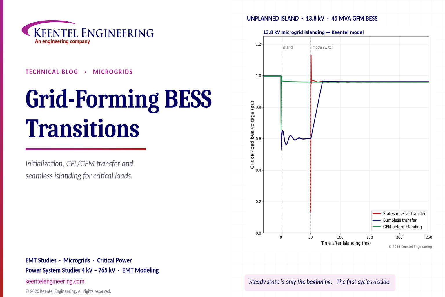
Explore grid-forming BESS initialization, GFL-to-GFM transitions, seamless islanding, EMT simulations, current limiting and microgrid protection.
By SANDIP R PATEL
•
October 23, 2026
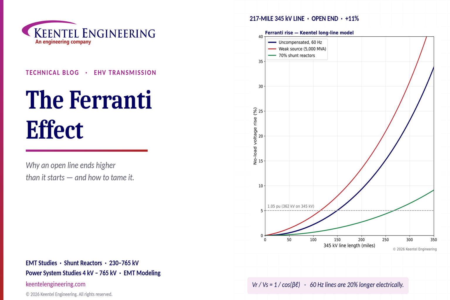
Explore the Ferranti effect in EHV transmission lines: voltage rise, 345 kV examples, switching overvoltages, shunt reactor sizing and mitigation.
By SANDIP R PATEL
•
October 23, 2026
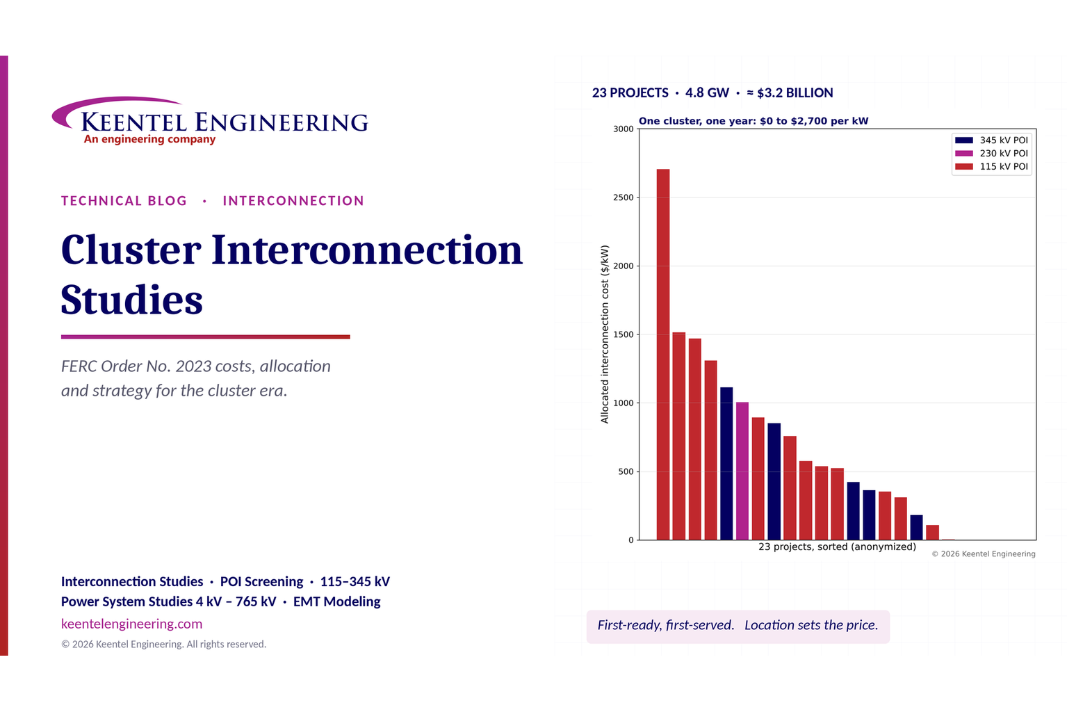
Explore cluster interconnection studies under FERC Order 2023, including network upgrades, cost allocation, withdrawal penalties and developer strategy.
By SANDIP R PATEL
•
October 21, 2026
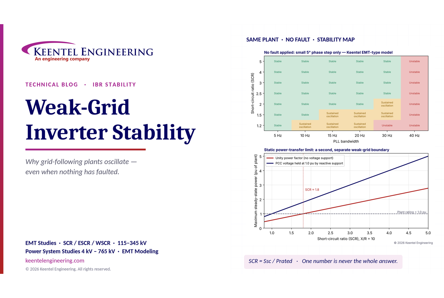
Learn why grid-following inverters become unstable without grid faults. Explore SCR, PLL interactions, EMT studies, grid strength, and mitigation.
By SANDIP R PATEL
•
October 21, 2026
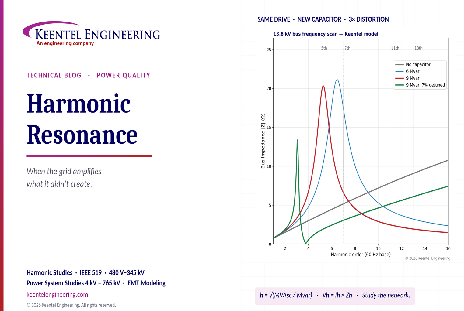
Learn how harmonic resonance amplifies distortion in power systems. Explore capacitor banks, detuned reactors, frequency scans, and IEEE 519 solutions.
By SANDIP R PATEL
•
October 20, 2026
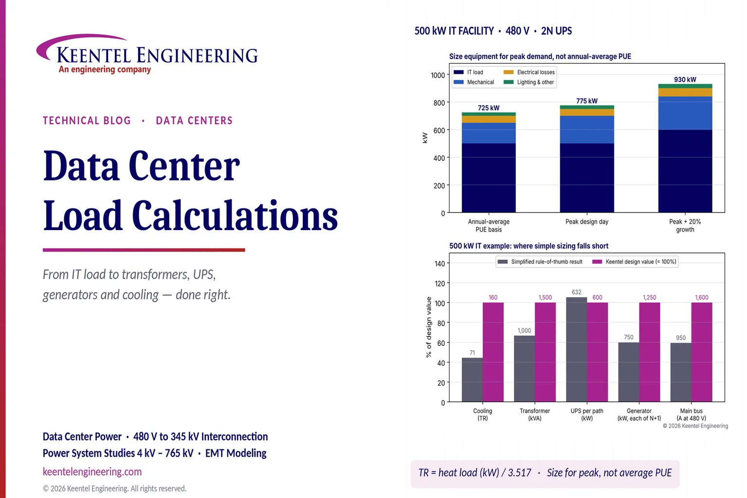
Learn data center electrical load calculations, including IT demand, PUE, UPS and generator sizing, cooling loads, redundancy, and worked US examples.
By SANDIP R PATEL
•
October 20, 2026
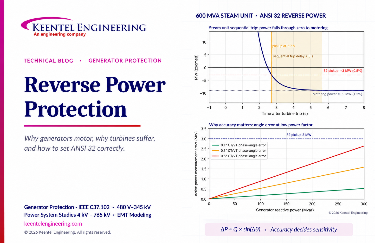
Learn reverse power protection (ANSI 32), generator motoring, relay pickup settings, time delays, sequential tripping and testing for US power plants.

By Team 2 Dexora
•
October 20, 2026
Explore grounding system testing with Keentel Engineering. Learn IEEE 80/81 methods, soil resistivity, ground resistance, and touch and step voltage safety.

By SANDIP R PATEL
•
October 13, 2026
Plan data center capacity with land screening, MW-per-acre estimates, grid power availability and interconnection feasibility studies from Keentel Engineering.





