
A Coordinated Electric System Interconnection Review—the utility’s deep-dive on technical and cost impacts of your project.
Challenge: Frequent false tripping using conventional electromechanical relays
Solution: SEL-487E integration with multi-terminal differential protection and dynamic inrush restraint
Result: 90% reduction in false trips, saving over $250,000 in downtime
ERCOT enforces all of the above through simulation, which means your model is your compliance case. The bar is now high:
- Whole-facility scope. The model must represent everything the IT load, the UPS and power conversion, the cooling plant, the protection and control systems in formats compatible with ERCOT's study platforms (PSS/E, PSCAD, TSAT).
- Real control loops, not approximations. Generic textbook representations are unacceptable. The model must capture the actual inner control behavior of your power electronics.
- Hardware-validated converter models. For electronic loads, the PSCAD model must be benchmarked against actual hardware testing including voltage ride-through and subsynchronous response. A model assembled from standard PSCAD library blocks fails by definition, because a generic block has never been tested against your vendor's hardware. The good news: validation is a hardware-type test, so results for a given converter product are reusable across every facility that uses it.
- Format migration. Facilities that previously submitted the older composite load model (CMLD) format must transition to EPRI's PERC1 format.
- Three checkpoints. Models are reviewed before the stability study begins (no model, no study), before each quarterly stability assessment, and for electronic loads one final time before energization, when you must submit as-built models with a documented comparison against the previously studied data and a sworn attestation that the model matches actual field settings. ERCOT's review takes 10 business days, extendable by 20 put it on your critical path.
- A living obligation. Change your technology, controls, or relay settings in a way that affects ride-through including converting a crypto mining site to an AI data center — and you've triggered a new interconnection study, even if your megawatts don't change.
| Parameter | Detail |
|---|---|
| System | 230 kV / 138 kV transmission corridors, wind and wet-snow icing exposure |
| Data basis | 15 years of minute-resolution forced-outage records + regional weather observations |
| Core methods | Event grouping, MVA performance curves, time-to-95%-restore, area outage rate curves, fragility modeling, rerun-history benefits, exceedance and log-domain risk metrics |
| Headline result | ≈85% of maximum resilience benefit at 60% of original capital; worst-event restoration window cut from 11 days to 5 in rerun-history terms |
| Decision supported | Capital portfolio selection; resilience plan filing; post-investment verification framework |
| System / Topic | Governing Standard(s) | What It Controls |
|---|---|---|
| Overall plant electrical distribution | IEEE 141 (Red Book); IEEE 666 | Distribution architecture, voltage selection, design of generating station auxiliary service systems |
| Power system studies | IEEE 399 (Brown Book); IEEE 551 | Load flow, symmetrical/asymmetrical short circuit, motor starting methodologies down to the lowest LV panelboard |
| Protection & coordination | IEEE 242 (Buff Book); IEEE 3004.5; IEEE C37 series | Generator relaying (21, 59N, 87G), time-current coordination, selective clearing between LV and MV tiers |
| GSU / UAT / SST transformers | IEEE C57.12.00 and C57 family | Transformer ratings, impedance, testing, loading |
| HV switchyard breakers | IEEE C37.06 | AC high-voltage circuit breaker preferred ratings |
| MV switchgear (13.8 kV) | IEEE C37.20.2; IEEE C37.20.7 | Metal-clad construction, compartmentalization, vacuum breakers; arc-resistant design with plenum venting |
| MV cable | UL 1072; ICEA S-93-639 (NEMA WC 74) | Type MV-105 shielded cable, 133% insulation level for HRG systems |
| LV switchgear (480 V) | IEEE C37.13; UL 1558 | Metal-enclosed LV power circuit breaker switchgear to 635 V, draw-out ACBs with electronic trip units |
| Motor control centers | UL 845; NEMA ICS 18 | LV-MCC construction, MCCB/MCP protection for motors under ~200 HP |
| Motors | NEMA MG-1 | Motor performance, starting characteristics, service factors |
| DC & battery systems | IEEE 485; IEEE 946 | Lead-acid battery sizing (125/250 VDC), DC auxiliary system design |
| Grounding | IEEE 80; IEEE 142 (Green Book) | Ground grid step/touch potential limits; system grounding including high-resistance grounding |
| Lightning protection | IEEE 998 | Direct-stroke shielding of switchyard and outdoor generator structures |
| Arc flash & electrical safety | IEEE 1584; NFPA 70E | Incident energy calculation; worker safety boundaries and PPE |
| Fire protection | NFPA 850 | Fire protection and risk management for combustion turbine generating plants |
| Installation code | NEC (NFPA 70); NESC | Wiring methods inside the plant fence; overhead/outdoor clearances at the switchyard |
| Interconnection & compliance | FERC LGIP; NERC MOD-025/026/027, PRC-019/024/029, FAC-008 | Interconnection process, model validation, protection/ride-through coordination, facility ratings |
| IFC / Construction Deliverable | Purpose |
|---|---|
| Stamped IFC packages | Legal basis for construction; P.E. responsible charge |
| Final relay settings & TCCs | Protection as-installed matches the coordination study |
| Calculation archive | Owner records; NERC audit evidence trail |
| Commissioning procedures | Safe, sequenced energization; MOD field testing |
| Construction support | RFIs, field changes, FAT/SAT witness |
| As-builts & model handoff | Operating baseline; future study currency |
Interlocking Engineering for EHV GIS Substations
Jul 09, 2026 | Blog
1. Why Interlocking Is a First-Order Design Input, Not an Afterthought
In an extra-high-voltage gas-insulated substation, the interlocking scheme is the last line of defense between a routine switching order and a catastrophic event. A disconnector opened under load, a breaker closed onto a grounded bus, or an earth switch applied to an energized section can destroy primary equipment, collapse a diameter, and put personnel at severe risk. Interlocking logic exists to make those events mechanically and electrically impossible — not merely procedurally discouraged.
At Keentel Engineering, we treat interlocking design and verification the same way we treat grid interconnection: as a first-order engineering input that must be resolved early, not a documentation task cleaned up at the end of a project. The interlocking philosophy shapes the bay layout, the control architecture, the SCADA point list, the maintenance procedures, and ultimately the operational flexibility of the substation for its entire service life.
This article walks through interlocking engineering for a 380–400 kV class GIS diameter arranged in the one-and-a-half breaker scheme. We cover the roles of the bus-side, middle, and line-side circuit breakers; the isolators and earth switches that surround them; the distinction between the service position and the test position; SF6 gas density interlocks; and the specific permissive conditions that govern each closing and opening operation. A detailed FAQ follows the main article.
2. The One-and-a-Half Breaker Diameter: Anatomy of the Bay
In a one-and-a-half breaker arrangement, two circuits share three circuit breakers connected in series between two main busbars. Each diameter contains a bus-side breaker tied to Bus 1, a second bus-side breaker tied to Bus 2, and a middle breaker shared between the two circuits. Each circuit taps the diameter between a bus-side breaker and the middle breaker.
Every circuit breaker in the diameter is flanked by two motor-operated isolators (disconnectors), and each isolator section carries its own maintenance earth switches. Line-side isolators connect each circuit to the diameter, line earth switches provide grounding for outgoing circuits, and dedicated busbar earth switches allow each main bus to be grounded for maintenance. Current transformer cores are distributed through the diameter to support protection zones that overlap across each breaker.
The value of this topology is redundancy: either circuit can remain in service with any single breaker out for maintenance, and a bus outage does not interrupt either circuit. But that same flexibility multiplies the number of possible switching states which is exactly why the interlocking matrix for a one-and-a-half breaker diameter is substantially more complex than for a single-bus or double-bus arrangement, and why it deserves rigorous engineering review at the design stage.
Keentel Perspective
The interlocking matrix is where the single-line diagram meets operational reality. Every cell in that matrix is a claim about what can never happen in the field. We recommend a formal, line-by-line interlocking review with the utility’s operations staff in the room before control wiring design is released for construction.
3. The "Complete Position" Operating Philosophy
Under normal operating conditions, a well-run one-and-a-half breaker diameter is maintained in what operators call the complete position: all three circuit breakers and all series isolators in the diameter are kept closed, even if one of the two circuits is de-energized at its remote end. If a circuit is out of service, its line isolator remains closed along with everything else in the string.
This practice delivers two operational benefits. First, restoration is fast returning the idle circuit to service requires only remote-end action rather than a local switching sequence. Second, it keeps the diameter’s protection zones intact and simplifies the operator’s mental model: the default state of the bay is "everything closed," and any departure from that state is a deliberate, logged exception associated with maintenance or a fault.
4. Status Signaling: Why "Fully Open" and "Fully Closed" Matter
Interlocking logic does not act on simple open/closed indications alone. GIS switchgear reports device positions with a richer vocabulary, and the distinction between an in-travel device and a device that has completed its stroke is fundamental to safe permissive logic.
| Signal | Meaning | Role in Interlocking Logic |
|---|---|---|
| O / CL | Open status / Closed status of a device | Basic state indication used for monitoring and SCADA display |
| FO | Fully Open — device has completed its opening stroke and is not in an intermediate position or under operation | Permissive condition: proves the device is definitively out of the circuit |
| FCL | Fully Closed — device has completed its closing stroke and is not in an intermediate position or under operation | Permissive condition: proves the current path through the device is complete and secure |
| SY | Synchro-check supervision required for the operation | Blocks breaker closing unless voltages across the breaker match in magnitude, phase, and frequency |
| M | Maintenance condition — synchro-check supervision is bypassed | Used only under controlled maintenance/test regimes |
| L / R / S | Command permitted from Local panel / Remote operator station / SCADA | Defines which control hierarchy may issue the command |
| E | Emergency operation | Overrides standard control-hierarchy restrictions in critical situations |
| SF6 Low Stage 1 | Low gas density — alarm stage | Warning threshold; restricts closing operations |
| SF6 Low Stage 2 | Low gas density — lockout stage | Blocking threshold; all breaker operation inhibited |
The engineering significance of FO and FCL is straightforward: an isolator caught mid-stroke has neither the dielectric withstand of the open position nor the current-carrying capability of the closed position. Permissive logic built on full-travel confirmation rather than momentary auxiliary contacts ensures that no downstream operation is enabled while any interlocked device is still in motion.
5. Circuit Breaker Interlocking: The Bus-Side Breaker
Consider the bus-side circuit breaker connected to Bus 1. It sits between two series isolators — a bus-side isolator toward the busbar and a diameter-side isolator toward the circuit tap — and each isolator section carries its own earth switches. The breaker is governed by two separate interlocking tables: one for closing and one for opening. The asymmetry between them is deliberate, and understanding it is essential for anyone writing or reviewing switching orders.
5.1 Closing in the Service Position
Closing a breaker in the service position means connecting it into a live network, so the permissive chain is the most restrictive in the entire scheme. Four independent conditions must be satisfied:
- Isolator status — Both series isolators flanking the breaker must be confirmed Fully Closed (FCL). This guarantees the electrical path through the breaker is continuous and secure before any current is asked to flow. The line isolator further out in the circuit may be either fully open or fully closed depending on the circuit’s operating state it is not part of this breaker’s closing permissive.
- Synchronization The synchro-check relay must confirm that voltage magnitude, phase angle, and frequency match across the open breaker contacts. Closing across a mismatch drives severe transient torques into rotating plant, stresses transformer windings, and can destabilize the local network. The synchro-check permissive is bypassed only under a controlled maintenance condition.
- SF6 gas density The breaker cannot be closed if gas density has fallen to the Stage 1 alarm threshold, and it is absolutely locked out at Stage 2. Closing is deliberately held to a stricter standard than opening: a breaker that closes with marginal gas may be called on to interrupt a fault an instant later with degraded arc-quenching capability.
- Control authority The close command is accepted from the control hierarchy defined in the interlocking table local, remote, or SCADA with the selector-switch position determining which path is live at any moment.
5.2 Opening: Fewer Conditions, One Critical Restriction
Opening a circuit breaker is intentionally easier than closing it. A breaker is the one device in the bay designed to interrupt load and fault current, so the logic never wants to obstruct a trip. Opening does not depend on synchronization, on the position of surrounding earth switches, or on maintenance status. The breaker can be opened with SF6 gas at the Stage 1 alarm level; only the Stage 2 lockout condition blocks it.
There is, however, one restriction that matters enormously: the breaker must not be operated while either of its series isolators is in motion. If the breaker changes state mid-stroke of an isolator, load current can be made or broken across the isolator’s contacts — contacts that have no arc-control capability whatsoever. The result is contact destruction, internal flashover in the GIS enclosure, and a forced outage of the diameter. The interlocking logic enforces this by blocking breaker commands whenever the flanking isolators report an in-travel condition.
Open commands are accepted from four control points: the local control cubicle at the equipment, the remote operator station, SCADA, and a dedicated emergency control path that overrides standard hierarchy restrictions in critical situations.
6. SF6 Gas Density Supervision: The Two-Stage Interlock
SF6 provides both the dielectric insulation and the arc-quenching medium for the breaker, and its effectiveness depends on gas density, not merely pressure. GIS installations therefore use temperature-compensated density monitors with two supervised thresholds feeding directly into the interlocking logic:
| Stage | Condition | Effect on Breaker Operation |
|---|---|---|
| Stage 1 — Alarm | Gas density has fallen to the first supervised threshold | Alarm raised to operators. Breaker may still be opened (tripping is preserved), but closing is not permitted. |
| Stage 2 — Lockout | Gas density has fallen to the second, critical threshold | All operation inhibited — the breaker can neither open nor close. The interrupter can no longer be relied upon to withstand or interrupt current safely. |
Design Note
The asymmetry between Stage 1 and Stage 2 is intentional and worth preserving in every scheme review: at alarm level the system still allows the breaker to remove itself from service, but refuses to let it take on new duty. Lockout at Stage 2 recognizes that operating a breaker with critically low gas density is more dangerous than leaving it in its current state while the gas system is attended to.
Modern gas monitoring extends beyond the hardwired interlock: networked density sensors, trend analysis, leak-rate forecasting, and alarm escalation through station automation systems give maintenance teams days or weeks of warning before an interlock threshold is ever reached. Keentel routinely specifies communicating density monitoring in new GIS designs so that Stage 1 alarms become rare events rather than routine ones.
7. Service Position vs. Test Position: Two States, Two Logics
Every withdrawable or GIS-class breaker installation distinguishes between two fundamental operating states, and the interlocking logic changes completely between them.
7.1 The Service Position
In the service position, the breaker is fully connected to the high-voltage power system and to its control and auxiliary circuits. Its primary contacts are engaged with the busbars and primary conductors; it conducts load current, interrupts fault current, and responds to protection and control commands. This is the breaker doing its job.
Three requirements define a healthy service position:
- Proper primary engagement — The primary contacts must be fully engaged with the high-voltage circuit. Partial engagement causes localized heating, arcing, and progressive contact damage.
- Control connectivity — Control and auxiliary circuits must be live and proven, so open/close commands and status feedback (position, alarms, trip events) flow reliably between the breaker and the control system or SCADA.
- Position interlocking — Interlocks must prevent the breaker from moving between service and any other position except through the correct, deliberate sequence.
Supporting safety measures include unambiguous position indication (mechanical and electronic), locking of the breaker in the service position during operation, and continuous monitoring of contact resistance, temperature, and gas density.
7.2 The Test Position
In the test position, the breaker is electrically and mechanically disconnected from the high-voltage system but remains connected to its control and auxiliary circuits. The breaker cannot conduct primary current in this state — and that is precisely the point. The test position exists so that the full secondary ecosystem around the breaker can be exercised without touching the live network.
The test position supports four categories of work:
- Routine operational testing — Exercising open/close operations, trip mechanisms, and auxiliary contacts with no primary consequence.
- Protection verification — Injecting into protection schemes — overcurrent, earth fault, differential — and proving trip paths end-to-end without disturbing the in-service system.
- Maintenance and inspection — Servicing and inspecting the breaker while it is positively isolated from the high-voltage circuit.
- Pre-commissioning tests — Proving every system on a newly installed or freshly serviced breaker before it is returned to service.
7.3 Side-by-Side Comparison
| Attribute | Service Position | Test Position |
|---|---|---|
| Primary circuit | Fully connected; conducts load and fault current | Positively disconnected; cannot conduct current |
| Control & auxiliary circuits | Connected and live | Connected and live |
| Series isolators | Must be Fully Closed (FCL) to permit breaker closing | Must be Fully Open (FO) to guarantee isolation |
| Synchro-check | Required for closing | Not required — no system voltages across the breaker |
| Control points for close | Per interlocking table (local / remote / SCADA) | Local, remote, and emergency only — SCADA closing disabled |
| SF6 interlock | Stage 1 blocks closing; Stage 2 blocks all operation | Stage 1 / Stage 2 thresholds still inhibit operation |
| Purpose | Normal network duty: switching, protection, isolation | Testing, maintenance, protection verification, pre-commissioning |
8. Closing the Breaker in the Test Position
When a breaker is placed in the test position, the interlocking logic inverts several of its service-position rules and the inversions are as instructive as the rules themselves.
- Isolation is mandatory — Both series isolators must be confirmed Fully Open. In service, closed isolators guarantee a continuous path; in test, open isolators guarantee complete separation from system voltage so the breaker can be cycled with zero risk of accidental energization.
- No synchro-check — With no system voltage on either side of the breaker, there is nothing to synchronize to. The synchro-check permissive is removed from the closing chain.
- SCADA closing disabled — Test-position operation is permitted from the local panel, the remote operator station, and the emergency path — but closing from SCADA is deliberately disabled. A dispatcher looking at a system-wide display should never be able to cycle a breaker that field personnel may be working around.
- SF6 interlock remains — Gas density supervision does not relax in the test position. If density falls below the Stage 1 or Stage 2 thresholds, operation is inhibited — a breaker with inadequate insulation should not be cycled even for test purposes.
Field Safety Insight
Disabling SCADA control in the test position is one of the quiet, high-value details of a well-designed interlocking scheme. It converts an administrative rule ("do not operate remotely during maintenance") into an engineered impossibility — which is the entire philosophy of interlocking in one sentence.
9. Isolator Interlocking: The Bus-Side Isolator
Isolators provide visible, verifiable isolation, but they have no capability to make or break load current. Every permissive in an isolator’s interlocking table exists to guarantee the isolator only ever operates on a dead, current-free section. The conditions differ sharply between service and test regimes.
9.1 Service Position Conditions
For the bus-side isolator — the device connecting the diameter to the main busbar — three conditions must be proven before operation is permitted in the service position:
- Breaker open — The associated circuit breaker must be open. With the breaker open, no current can flow through the isolator during its stroke.
- Adjacent earth switches open — The earth switches on both isolator sections adjacent to the breaker must be open. This prevents the isolator from connecting an energized busbar into a grounded section — a bolted fault by design.
- Busbar earth switch open — The busbar earth switch on the associated main bus must be open, proving the busbar itself is not grounded while the isolator connects to it.
9.2 Test Position Conditions
In the test (maintenance) regime the logic changes character entirely:
- Breaker status becomes irrelevant — The isolator may be operated regardless of whether the circuit breaker is open or closed. During maintenance the primary circuit is already dead and grounded, so the breaker’s position is no longer a safety constraint — and maintenance activities frequently require cycling isolators with the breaker in either state.
- Earth switches must be closed —
The adjacent earth switch and the busbar earth switch must be closed. This is the exact inversion of the service-position rule: in service, grounding anywhere near the isolator is forbidden; in test, positive grounding everywhere around the work area is mandatory. The grounded envelope is what protects personnel from induced voltages and inadvertent energization.
10. Isolator Interlocking: The Diameter-Side Isolator
The isolator on the other flank of the breaker — between the breaker and the circuit tap — follows the same philosophy with its own set of interlocked devices.
10.1 Service Position Conditions
- Breaker open — The associated circuit breaker must be open, for the same current-free reason as before.
- All adjacent earth switches open — All earth switches electrically adjacent to the isolator — the earth switches on both breaker flanks and the earth switch on the circuit-tap section — must be open, preventing any inadvertent grounding of the operating path.
10.2 Test Position Conditions
- Breaker status irrelevant — The isolator may be operated regardless of breaker status, providing the flexibility maintenance work requires.
- Grounded envelope required — The earth switch on the breaker-side section and the earth switch on the circuit-tap section must be closed, keeping the entire working envelope positively grounded throughout the operation.
The Underlying Pattern
Read enough interlocking tables and a single pattern emerges. Service position: prove the path is dead (breaker open) and ungrounded (earth switches open) before an isolator moves. Test position: prove the path is dead and grounded before anything moves. The earth-switch conditions flip polarity between the two regimes and that flip is the signature of a correctly engineered scheme.
11. How Keentel Engineering Supports GIS Interlocking Projects
Interlocking engineering sits at the intersection of primary design, protection and control, and operations — which is exactly where Keentel Engineering works every day. Our support for utility and developer clients on EHV GIS projects includes:
- Interlocking design & review — Development and independent review of interlocking matrices and permissive tables for one-and-a-half breaker, double-bus, and breaker-and-a-half hybrid arrangements.
- Factory & site acceptance testing — Verification that vendor GIS interlocking logic, hardwired and IEC 61850 GOOSE-based, matches the approved scheme — including witness testing of service/test position transfers, SF6 threshold responses, and control-hierarchy behavior.
- Operations documentation — Switching-order development, standard operating procedures for line isolation and restoration, and operator training material aligned to the as-built interlocking scheme.
- Full-lifecycle engineering — Substation and interconnection engineering across the full project lifecycle — from POI studies and EMT modeling through detailed substation design commissioning support, and NERC compliance.
If your project involves a new GIS bay, a retrofit into an existing diameter, or an interlocking scheme that has never had an independent line-by-line review, our team can help. Contact Keentel Engineering at 813-389-7871 or contact@keentelengineering.c
Frequently Asked Questions
The questions below expand on the concepts in the article and reflect the questions our engineers most often field from operations, maintenance, and protection teams working on EHV GIS installations.
Q1. What is substation interlocking, and why is it critical in a GIS installation?
Interlocking is the system of engineered permissive conditions that determines when each switching device — circuit breaker, isolator, or earth switch — is allowed to operate. Its purpose is to make dangerous switching states physically impossible rather than merely prohibited by procedure: opening an isolator under load, closing a breaker onto a grounded bus, or applying an earth switch to an energized section. In GIS the stakes are amplified because all primary equipment shares a common gas-insulated enclosure; an internal flashover caused by a mis-operation can damage multiple compartments, force a long forced outage, and require factory-level repair. Interlocking converts operating rules into engineered constraints enforced by the control system itself.
Q2. How does the one-and-a-half breaker scheme work, and why does it complicate interlocking?
Two circuits share three series circuit breakers between two main busbars: a breaker at each bus and a middle breaker shared by both circuits, with each circuit tapping the diameter between a bus breaker and the middle breaker. The topology gives excellent redundancy — any single breaker or either bus can be removed from service without dropping a circuit. The cost of that flexibility is combinatorial: with three breakers, six or more isolators, numerous earth switches, and busbar earth switches all interacting, the number of legitimate and illegitimate device-state combinations is far larger than in simpler bus arrangements. Each device therefore needs its own interlocking table for each operation and each control regime, and the full matrix warrants systematic engineering review rather than case-by-case reasoning.
Q3. What is the "complete position" and why do operators maintain it?
The complete position is the normal-state convention of keeping every breaker and isolator in the diameter closed, even when one of the two circuits is switched off at its remote end. If a circuit is out of service, its line isolator stays closed along with the rest of the string. The benefits are rapid restoration — the idle circuit can be returned to service without a local switching sequence — plus an intact protection zone structure and a simple operating baseline in which any open device is a deliberate, documented exception rather than routine ambiguity.
Q4. What is the difference between a breaker’s service position and test position?
In the service position the breaker is fully engaged with the high-voltage circuit and with its control and auxiliary systems: it carries load, interrupts faults, and responds to protection. In the test position the breaker is positively disconnected from the primary circuit — it cannot conduct current — but remains connected to control and auxiliary circuits so its mechanisms, trip paths, protection schemes, alarms, and communications can all be exercised safely. Service is the breaker doing its network job; test is the breaker available for proving and maintenance with zero primary risk.
Q5. Why must the series isolators be fully closed before a breaker can close in service?
Because the breaker is about to establish load current through the entire string. If either flanking isolator were open, partially traveled, or in motion, closing the breaker would either accomplish nothing useful or — far worse — cause current to be established through isolator contacts that are not fully engaged. Requiring confirmed Fully Closed (FCL) status on both isolators proves the current path is mechanically complete and electrically secure before the breaker adds current to it. Note that the requirement uses full-travel confirmation, not a momentary contact: an isolator mid-stroke satisfies neither the open nor the closed condition and blocks the permissive.
Q6. What is a synchro-check, and when is it bypassed?
A synchro-check relay compares the voltages on the two sides of an open breaker and permits closing only when magnitude, phase angle, and frequency agree within set limits. Closing across a mismatch imposes severe transient torque on generators and motors, stresses transformer windings, and can trigger power swings or instability. The synchro-check is a mandatory permissive for closing in the service position. It is bypassed in two situations only: under a controlled maintenance condition explicitly flagged in the interlocking scheme, and in the test position — where the breaker is disconnected from system voltage entirely, so there is nothing to synchronize to.
Q7. How do the SF6 Stage 1 and Stage 2 thresholds affect breaker operation?
Stage 1 is the alarm threshold: gas density has dropped enough to warrant attention. At Stage 1, the breaker can still be opened — the scheme preserves the ability to trip and to remove the breaker from service — but closing is blocked, because a breaker that closes with marginal gas may immediately be called on to interrupt a fault with degraded arc-quenching capability. Stage 2 is the lockout threshold: density is critically low and the breaker can neither open nor close. At that point operating the breaker in any direction is judged more dangerous than leaving it in its present state while the gas system is repaired and refilled.
Q8. Why is opening a breaker subject to fewer interlocks than closing it?
The breaker is the only device in the bay designed to interrupt current, and the scheme must never obstruct a trip. Opening therefore requires no synchronization, no earth-switch conditions, and no maintenance-status checks, and it remains available at the SF6 Stage 1 alarm level. The one restriction that applies to both directions is the isolator-in-motion block: the breaker must not change state while either flanking isolator is mid-stroke, because that could force current to be made or broken across isolator contacts that have no interrupting capability.
Q9. What happens if a breaker operates while an isolator is still in motion?
The isolator’s contacts would be asked to make or break load current — a duty they are entirely unequipped for. Isolator contacts have no arc-control structure; the resulting arc can destroy the contact system, initiate an internal flashover within the GIS compartment, generate decomposition byproducts in the gas, and force an extended outage of the diameter for factory-level repair. This failure mode is why the interlocking logic hard-blocks breaker commands whenever a flanking isolator reports an in-travel state, and why FO/FCL full-travel signals — not transient auxiliary contacts — are used as the permissive inputs.
Q10. Why is SCADA control disabled when a breaker is in the test position?
The test position exists so field personnel can work on and around the breaker. A dispatcher at a system-wide SCADA console has no visibility into who is standing next to the mechanism. Disabling the SCADA close path in test converts the administrative rule "do not operate remotely during maintenance" into an engineered impossibility. Local, remote-operator, and emergency paths remain available under the controlled conditions of the test regime, where the people issuing commands are part of the maintenance activity itself.
Q11. Why do the earth-switch conditions invert between service and test operation of an isolator?
In the service position, the network around the isolator is energized or about to be energized, so any closed earth switch in the operating path would create a bolted fault the moment the isolator connects it to a live source — hence every adjacent earth switch, including the busbar earth switch, must be proven open. In the test position, the section is deliberately dead and the priority flips to personnel protection: the adjacent earth switches and busbar earth switch must be proven closed so the entire working envelope is positively grounded against induced voltage and inadvertent energization. The inversion is not an inconsistency; it is the scheme correctly serving two different safety objectives.
Q12. Why can isolators be operated regardless of breaker status in the test position?
In the service regime, "breaker open" is the proof that no current will flow through the isolator during its stroke. In the test regime that proof is provided differently: the section is already isolated and grounded, so no current can flow regardless of the breaker’s position. Removing the breaker-status condition gives maintenance teams the flexibility they genuinely need — many test and inspection procedures require cycling isolators with the breaker deliberately closed or deliberately open — without giving up any actual safety margin.
Q13. What roles do busbar earth switches play in the interlocking scheme?
Busbar earth switches ground an entire main bus for maintenance. They appear in the interlocking logic in both directions: a bus-side isolator cannot be operated in service unless the busbar earth switch is open (proving the bus is not grounded while being connected to the diameter), and in the test regime the busbar earth switch must be closed before the bus-side isolator operates (proving the maintenance envelope is grounded). Their interlocks also work in reverse — the busbar earth switch itself can only close when every isolator connecting that bus to potential sources is proven open.
Q14. What is typically verified during interlocking acceptance testing?
A thorough acceptance program walks the interlocking matrix cell by cell: every permitted operation is demonstrated, and — just as important — every blocked operation is attempted and proven to fail. Testing covers service and test position transfers; breaker closing with each isolator condition deliberately unsatisfied; synchro-check blocking and its authorized bypass; SF6 Stage 1 and Stage 2 responses (typically simulated at the density monitor); control-hierarchy behavior across local, remote, SCADA, and emergency paths, including the SCADA disable in test position; and earth-switch permissives in both regimes. For IEC 61850-based schemes, GOOSE-message supervision and failure modes are verified as well. Keentel recommends witnessed testing with the utility’s operations staff participating, so the people who will write switching orders have seen the scheme prove itself.
Q15. How should interlocking be handled during the design phase of a new GIS project?
Treat it as a first-order design input. The interlocking philosophy should be settled alongside the single-line diagram and bus arrangement — not reverse-engineered from vendor drawings after switchgear is ordered. Early decisions include the control hierarchy (local/remote/SCADA/emergency authority for each device and regime), hardwired versus GOOSE-based permissive transport, the FO/FCL signaling standard, SF6 threshold coordination with the monitoring system, and the operational conventions (such as the complete position) that the scheme must support. An independent line-by-line review of the vendor’s interlocking tables before control wiring release consistently catches errors that are inexpensive on paper and very expensive in commissioning.
About Keentel Engineering
Keentel Engineering is a power systems and grid interconnection consulting firm serving utilities, developers, and independent power producers nationwide. Our services span EMT and PSS/E modeling,
POI interconnection engineering, substation and
transmission line design, utility-scale renewables and BESS engineering, owner’s engineer services, and NERC O&P compliance. We believe grid interconnection — and the interlocking, protection, and control engineering that supports it — is a first-order design input, not a late-stage administrative step.
| Office | Address |
|---|---|
| Tampa (HQ) | 400 N Ashley Dr STE #2600, Tampa, FL 33602 |
| Austin | 5900 Balcones Dr STE 100, Austin, TX |
| Sacramento | Sacramento, CA |
| Baltimore | Baltimore, MD |
Disclaimer:
This document is published by Keentel Engineering for general informational and educational purposes. It does not constitute engineering advice for any specific installation, and switching or interlocking decisions for any facility must be based on that facility’s approved drawings, interlocking tables, and operating procedures. All product names, trademarks, and registered trademarks referenced are the property of their respective owners. Keentel Engineering is not affiliated with, endorsed by, or sponsored by any equipment manufacturer or organization mentioned or implied herein.

About the Author:
Sandip "Sonny" R. Patel, P.E.
IEEE Senior Member · Founder & CEO, Keentel Engineering
In 1995, Sonny Patel earned his Electrical Engineering degree from the University of Illinois. But degrees don't build legacies — action does.
For three decades, he has worked the power industry from every side of the table: 16 years as a utility engineer at Exelon/Commonwealth Edison; generation leadership across hydroelectric, industrial steam turbine, and a 9 GW renewable fleet; NERC Regional Entity Senior Compliance Engineer and Audit Team Lead, auditing some of the nation's largest utilities; and testing and commissioning lead on equipment up to 765 kV — the very top of the North American grid.Utility. Generator. Regulator. Consultant. Few engineers have seen all four seats. Fewer still have sat in them.
His experience spans nuclear, hydro, conventional generation, renewables, oil and gas, mining — and today's data centers, where he is authoring a three-book series on data center design. He is a Licensed Professional Engineer in six states and a Licensed Electrical Contractor in Florida (Unlimited EC) — he doesn't just design the work; he's qualified to stand behind its execution.Today, as Founder and CEO of Keentel Engineering, Sonny leads a nationwide team of engineers delivering substation design, power system studies, NERC compliance, and commissioning — done right, coast to coast.Three decades. Every side of the table. One standard: accountable engineering.
Services

Let's Discuss Your Project
Let's book a call to discuss your electrical engineering project that we can help you with.
About the Author:
Sandip "Sonny" R. Patel, P.E.
IEEE Senior Member · Founder & CEO, Keentel Engineering
In 1995, Sonny Patel earned his Electrical Engineering degree from the University of Illinois. But degrees don't build legacies — action does.
For three decades, he has worked the power industry from every side of the table: 16 years as a utility engineer at Exelon/Commonwealth Edison; generation leadership across hydroelectric, industrial steam turbine, and a 9 GW renewable fleet; NERC Regional Entity Senior Compliance Engineer and Audit Team Lead, auditing some of the nation's largest utilities; and testing and commissioning lead on equipment up to 765 kV — the very top of the North American grid.
Utility. Generator. Regulator. Consultant. Few engineers have seen all four seats. Fewer still have sat in them.
His experience spans nuclear, hydro, conventional generation, renewables, oil and gas, mining — and today's data centers, where he is authoring a three-book series on data center design. He is a Licensed Professional Engineer in six states and a Licensed Electrical Contractor in Florida (Unlimited EC) — he doesn't just design the work; he's qualified to stand behind its execution.
Today, as Founder and CEO of Keentel Engineering, Sonny leads a nationwide team of engineers delivering substation design, power system studies, NERC compliance, and commissioning — done right, coast to coast.Three decades. Every side of the table. One standard: accountable engineering.
Leave a Comment
Thank you for contacting us.
We will get back to you as soon as possible.
We will get back to you as soon as possible.
Oops, there was an error sending your message.
Please try again later.
Please try again later.
Related Posts
By SANDIP R PATEL
•
October 23, 2026
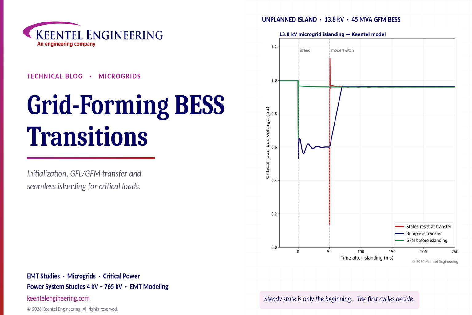
Explore grid-forming BESS initialization, GFL-to-GFM transitions, seamless islanding, EMT simulations, current limiting and microgrid protection.
By SANDIP R PATEL
•
October 23, 2026
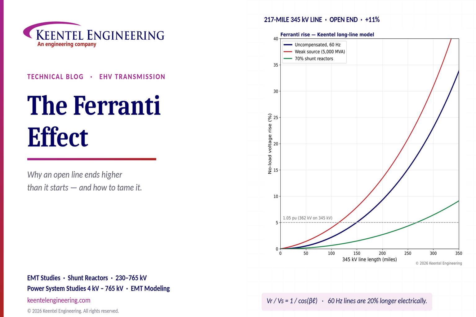
Explore the Ferranti effect in EHV transmission lines: voltage rise, 345 kV examples, switching overvoltages, shunt reactor sizing and mitigation.

By SANDIP R PATEL
•
October 23, 2026
Explore cluster interconnection studies under FERC Order 2023, including network upgrades, cost allocation, withdrawal penalties and developer strategy.
By SANDIP R PATEL
•
October 21, 2026
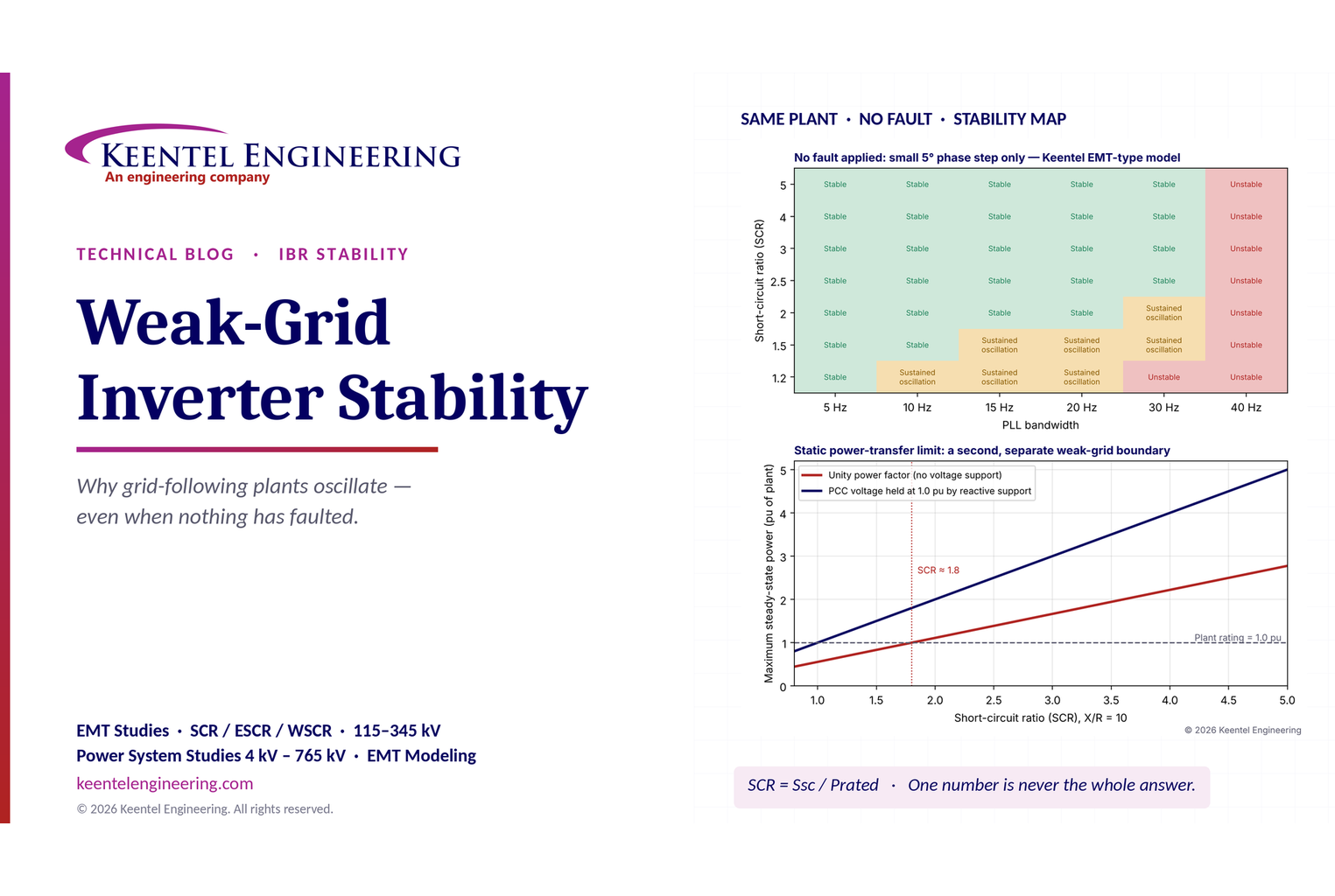
Learn why grid-following inverters become unstable without grid faults. Explore SCR, PLL interactions, EMT studies, grid strength, and mitigation.
By SANDIP R PATEL
•
October 21, 2026
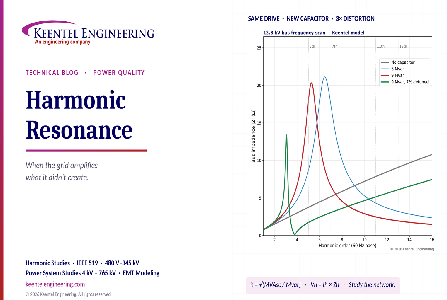
Learn how harmonic resonance amplifies distortion in power systems. Explore capacitor banks, detuned reactors, frequency scans, and IEEE 519 solutions.
By SANDIP R PATEL
•
October 20, 2026
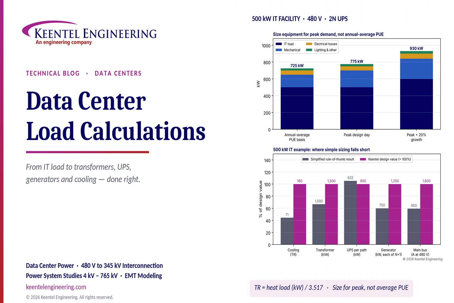
Learn data center electrical load calculations, including IT demand, PUE, UPS and generator sizing, cooling loads, redundancy, and worked US examples.
By SANDIP R PATEL
•
October 20, 2026
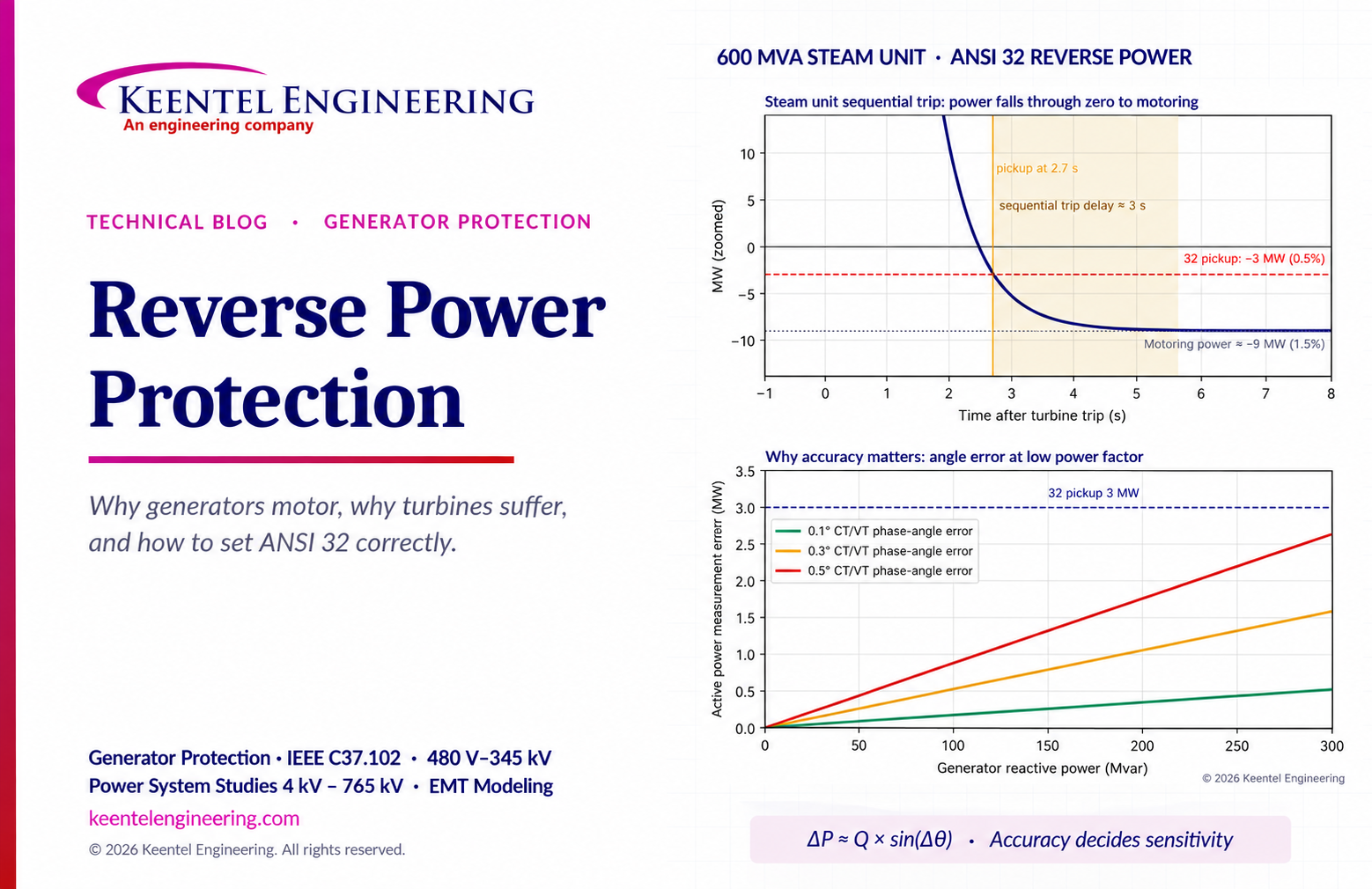
Learn reverse power protection (ANSI 32), generator motoring, relay pickup settings, time delays, sequential tripping and testing for US power plants.

By Team 2 Dexora
•
October 20, 2026
Explore grounding system testing with Keentel Engineering. Learn IEEE 80/81 methods, soil resistivity, ground resistance, and touch and step voltage safety.

By SANDIP R PATEL
•
October 13, 2026
Plan data center capacity with land screening, MW-per-acre estimates, grid power availability and interconnection feasibility studies from Keentel Engineering.





