
A Coordinated Electric System Interconnection Review—the utility’s deep-dive on technical and cost impacts of your project.
Challenge: Frequent false tripping using conventional electromechanical relays
Solution: SEL-487E integration with multi-terminal differential protection and dynamic inrush restraint
Result: 90% reduction in false trips, saving over $250,000 in downtime
ERCOT enforces all of the above through simulation, which means your model is your compliance case. The bar is now high:
- Whole-facility scope. The model must represent everything the IT load, the UPS and power conversion, the cooling plant, the protection and control systems in formats compatible with ERCOT's study platforms (PSS/E, PSCAD, TSAT).
- Real control loops, not approximations. Generic textbook representations are unacceptable. The model must capture the actual inner control behavior of your power electronics.
- Hardware-validated converter models. For electronic loads, the PSCAD model must be benchmarked against actual hardware testing including voltage ride-through and subsynchronous response. A model assembled from standard PSCAD library blocks fails by definition, because a generic block has never been tested against your vendor's hardware. The good news: validation is a hardware-type test, so results for a given converter product are reusable across every facility that uses it.
- Format migration. Facilities that previously submitted the older composite load model (CMLD) format must transition to EPRI's PERC1 format.
- Three checkpoints. Models are reviewed before the stability study begins (no model, no study), before each quarterly stability assessment, and for electronic loads one final time before energization, when you must submit as-built models with a documented comparison against the previously studied data and a sworn attestation that the model matches actual field settings. ERCOT's review takes 10 business days, extendable by 20 put it on your critical path.
- A living obligation. Change your technology, controls, or relay settings in a way that affects ride-through including converting a crypto mining site to an AI data center — and you've triggered a new interconnection study, even if your megawatts don't change.
| Parameter | Detail |
|---|---|
| System | 230 kV / 138 kV transmission corridors, wind and wet-snow icing exposure |
| Data basis | 15 years of minute-resolution forced-outage records + regional weather observations |
| Core methods | Event grouping, MVA performance curves, time-to-95%-restore, area outage rate curves, fragility modeling, rerun-history benefits, exceedance and log-domain risk metrics |
| Headline result | ≈85% of maximum resilience benefit at 60% of original capital; worst-event restoration window cut from 11 days to 5 in rerun-history terms |
| Decision supported | Capital portfolio selection; resilience plan filing; post-investment verification framework |
| System / Topic | Governing Standard(s) | What It Controls |
|---|---|---|
| Overall plant electrical distribution | IEEE 141 (Red Book); IEEE 666 | Distribution architecture, voltage selection, design of generating station auxiliary service systems |
| Power system studies | IEEE 399 (Brown Book); IEEE 551 | Load flow, symmetrical/asymmetrical short circuit, motor starting methodologies down to the lowest LV panelboard |
| Protection & coordination | IEEE 242 (Buff Book); IEEE 3004.5; IEEE C37 series | Generator relaying (21, 59N, 87G), time-current coordination, selective clearing between LV and MV tiers |
| GSU / UAT / SST transformers | IEEE C57.12.00 and C57 family | Transformer ratings, impedance, testing, loading |
| HV switchyard breakers | IEEE C37.06 | AC high-voltage circuit breaker preferred ratings |
| MV switchgear (13.8 kV) | IEEE C37.20.2; IEEE C37.20.7 | Metal-clad construction, compartmentalization, vacuum breakers; arc-resistant design with plenum venting |
| MV cable | UL 1072; ICEA S-93-639 (NEMA WC 74) | Type MV-105 shielded cable, 133% insulation level for HRG systems |
| LV switchgear (480 V) | IEEE C37.13; UL 1558 | Metal-enclosed LV power circuit breaker switchgear to 635 V, draw-out ACBs with electronic trip units |
| Motor control centers | UL 845; NEMA ICS 18 | LV-MCC construction, MCCB/MCP protection for motors under ~200 HP |
| Motors | NEMA MG-1 | Motor performance, starting characteristics, service factors |
| DC & battery systems | IEEE 485; IEEE 946 | Lead-acid battery sizing (125/250 VDC), DC auxiliary system design |
| Grounding | IEEE 80; IEEE 142 (Green Book) | Ground grid step/touch potential limits; system grounding including high-resistance grounding |
| Lightning protection | IEEE 998 | Direct-stroke shielding of switchyard and outdoor generator structures |
| Arc flash & electrical safety | IEEE 1584; NFPA 70E | Incident energy calculation; worker safety boundaries and PPE |
| Fire protection | NFPA 850 | Fire protection and risk management for combustion turbine generating plants |
| Installation code | NEC (NFPA 70); NESC | Wiring methods inside the plant fence; overhead/outdoor clearances at the switchyard |
| Interconnection & compliance | FERC LGIP; NERC MOD-025/026/027, PRC-019/024/029, FAC-008 | Interconnection process, model validation, protection/ride-through coordination, facility ratings |
| IFC / Construction Deliverable | Purpose |
|---|---|
| Stamped IFC packages | Legal basis for construction; P.E. responsible charge |
| Final relay settings & TCCs | Protection as-installed matches the coordination study |
| Calculation archive | Owner records; NERC audit evidence trail |
| Commissioning procedures | Safe, sequenced energization; MOD field testing |
| Construction support | RFIs, field changes, FAT/SAT witness |
| As-builts & model handoff | Operating baseline; future study currency |
Data Center Model Quality, Hardware Validation & Load-Fluctuation Mitigation

Jul 08, 2026 | Blog
How EMT Model Quality Testing, Hardware-in-the-Loop Validation, and Megawatt-Scale Testing De-Risk Large-Load Interconnection
The interconnection conversation for AI data centers has fundamentally changed. Two years ago, most utilities treated a large load as a passive megawatt number on a one-line diagram. Today, transmission operators on both sides of the Atlantic are demanding vendor-specific EMT models, model quality tests, hardware benchmarking, and ride-through performance guarantees before a single GPU rack energizes. A recent industry panel on hardware testing and model quality assessment featuring transmission system operators, a U.S. national laboratory, and specialist EMT consultancies made one thing unmistakably clear: the model is now part of the interconnection agreement, and a bad model can stall gigawatts of load.
At Keentel Engineering, we treat grid interconnection requirements FERC LGIP procedures, NERC MOD/PRC/FAC obligations, and ISO-specific large-load rules as first-order design inputs, not late-stage administrative steps. This article distills what the industry's leading testing and modeling practitioners are now expecting from data center developers, and what it means for your project schedule, your equipment selection, and your interconnection risk.
1. Why Large Loads Suddenly Look Like Inverter-Based Resources
Modern AI data centers are packed with power electronics: server power supplies, double-conversion UPS systems, static transfer switches, VFD-driven cooling, and increasingly on-site BESS and STATCOM devices. Electrically, a gigawatt-class AI campus behaves less like a traditional industrial load and more like an inverter-based resource (IBR) operating in reverse. It is fast, non-linear, sensitive to weak-grid conditions, and capable of tripping or refusing to reconnect in ways conventional composite load models simply cannot represent.
The consequences are no longer hypothetical. In one widely discussed 2024 event, a routine 230 kV feeder fault near a 1.5 GW data center facility triggered repeated failed reclosure attempts: the facility's protection and controls judged the grid 'not stable enough' to reconnect, while the utility urgently needed that load back to preserve system stability. Roughly half a dozen reclosure attempts followed. The root cause was not a single device failure it was the absence of coordinated control, protection, and grid-interface behavior that was never studied, never modeled, and never tested before energization.
Grid operators have taken notice. ERCOT's interconnection queue now contains more than 400 GW of large-load requests, the vast majority being data centers and computational loads at the 1–2 GW scale. European TSOs report tens of gigawatts of new demand connection inquiries within a two-year window figures comparable to their entire existing peak load. The response has been a wave of new grid codes, modeling requirements, and model quality test (MQT) frameworks aimed squarely at large computational loads.
Keentel Insight
If your interconnection strategy still treats the EMT model as a deliverable to be 'handled later by the vendor,' you are carrying schedule risk measured in quarters, not weeks. Model quality checkpoints are now embedded in interconnection milestones a rejected model can freeze your energization ramp.
2. The New Regulatory Landscape: Ride-Through Is Now a Requirement, Not a Courtesy
2.1 ERCOT: NOGRR282 and PGRR144
ERCOT has moved decisively. Nodal Operating Guide Revision Request 282 (NOGRR282), approved by the ERCOT Board in mid-2025, defines voltage and frequency ride-through performance requirements for large computational loads (LCLs). Key expectations include continued power consumption through defined low-voltage and high-voltage bands, and restoration of load to pre-disturbance levels within two seconds of voltage recovery after a cleared fault.
In parallel, Planning Guide Revision Request 144 (PGRR144) establishes the data submission and model review machinery: a large-load data survey (on the order of 69 questions spanning fundamentals through protection settings and ride-through characteristics), a formal Model Quality Test framework, and defined model checkpoints throughout the interconnection process. Models must be delivered and cross-validated across three platforms PSS/E for positive-sequence dynamics, PSCAD for high-fidelity EMT, and TSAT for real-time operational security assessment with the PSS/E response benchmarked against the PSCAD response as an explicit quality gate.
PGRR144 defines three principal model checkpoints: before stability study entry (demonstrating voltage ride-through capability), before the Quarterly Stability Assessment (full MQT and multi-platform model submission), and for large computational loads only a final as-studied versus as-built model reconciliation before initial energization. Loads co-located behind existing or new generation face an additional, more rigorous layer of review through the generation interconnection process.
2.2 European TSO Practice: Models as a Condition of Energization
European transmission operators are converging on similar principles, in some respects moving even faster. One Nordic TSO facing roughly 54 GW of new demand connection inquiries across 2024- 2025 against a national peak load of only 16 GW has issued PSS/E and PSCAD modeling requirements for demand facilities and released a new demand grid code introducing low-voltage ride-through, over-voltage ride-through, phase-jump performance, sub-synchronous active power oscillation limits, and post-fault active power recovery requirements (recovery within one second for facilities above 30 MW).
Two features of this approach deserve particular attention from developers:
- Staged model acceptance tied to energization blocks. The first plant model is due six months before the interim operational notice. The facility may then ramp in 30 MW increments but each additional block is only released after the updated model passes validation. The full-plant model must be accepted before the final operational notice and unrestricted operation.
- Vendor-specific 'real-code' EMT models for UPS systems. Generic library representations are accepted only as a bridge. UPS and power-supply equipment must ultimately be represented by manufacturer-specific models embedding actual controller code, validated against factory test results.
Keentel Insight
The pattern is unmistakable across jurisdictions: model quality is being tied directly to your revenue ramp. Under staged-acceptance regimes, every week a model languishes in review is a week your capacity and your customers' compute sits idle.
3. Why Generic Models Fail and What 'Model Quality' Actually Means
The industry learned this lesson the hard way with inverter-based generation. Major solar-loss events in Texas in 2021 and 2022 with 1.1 GW and 1.7 GW of unintentional curtailment respectively occurred at facilities that had completed conventional PSCAD and PSS/E studies. Root-cause analyses pointed to phenomena that generic or poorly parameterized models could not capture: PLL loss of synchronism, inverter AC overvoltage response, momentary cessation, and unmodeled control-loop and communication behavior.
Large computational loads inherit every one of these vulnerabilities, plus several of their own. Based on the practices now emerging from TSOs, national laboratories, and EMT specialists, a defensible data center model must capture:
- Real-code power supply and UPS behavior. A 100 MW step at the GPU level may appear at the medium-voltage bus as a shaped ramp or as a 120 MW transient with overshoot, meaning the mitigation system must compensate more than the nominal load change. Only manufacturer real-code models capture this reliably.
- Control and communication latency. In active compensation schemes, a single millisecond of additional measurement, processing, filtering, or communication delay can swing a facility from compliant to non-compliant. Latency values in models should be deliberately conservative (worst-case) rather than tuned to pass.
- Impedance fidelity for passive mitigation paths. For double-conversion UPS and grid-forming BESS solutions, battery internal impedance and lead impedances determine whether the DC bus truly decouples load transients from the grid. Modeling the DC bus as an ideal voltage source hides ripple that appears on the AC side in reality.
- Correct measurement and monitoring practice. Instantaneous active power in EMT tools must be evaluated with minimal smoothing — a typical 20 ms filter constant suppresses everything above roughly 8 Hz and can mask the very fluctuations a grid requirement targets. A ~1 ms filter preserves the phenomena of interest.
- Realistic load ramp profiles. A load profile can be chosen to pass or chosen to fail; neither is acceptable. Mitigation studies must be run against realistic AI training and inference ramp characteristics, including synchronized load-crash scenarios.
- Aggregation and functional description. The connecting entity should propose and justify how thousands of racks, UPS branches, and mitigation devices aggregate into a study model, and document plant behavior in normal, disturbed, and load-sharing/parallel-facility conditions.
4. The Validation Continuum: From Offline EMT to Megawatt-Scale Hardware
A recurring theme among practitioners is that offline simulation is necessary but not sufficient. The emerging best practice is a three-stage validation continuum, with each stage retiring risk the previous stage cannot see.
4.1 Stage 1 Offline EMT and Positive-Sequence Studies
PSCAD/EMT studies remain the foundation: ride-through screening, phase-jump response, load-fluctuation mitigation sizing, and sub-synchronous behavior. For fluctuation-mitigation studies, a compact single-machine-infinite-bus–style
EMT model — analogous to an MQT setup — is generally sufficient; a wide-area model is not required. System strength (SCR and X/R) must be represented faithfully, since grid-forming devices' initial phase-jump power injection depends directly on it. Converter models should be average-value models for simulation performance, with vendor real-code models for all UPS systems.
4.2 Stage 2 Controller Hardware-in-the-Loop (CHIL)
In offline simulation, time freezes while the solver exchanges data with the control model; in the real world, the clock keeps ticking. Hardware-in-the-loop testing closes that gap by connecting the physical controllers power conversion system controllers, plant/power management systems, protection relays, and even metering with synchrophasor interfaces to a real-time simulator representing the facility and the grid.
The payoff is discovering integration defects before commissioning. In one 20 MW data center project in the Middle East, CHIL testing exposed control 'jittering' during grid-forming to grid-following transitions of the power conversion system behavior invisible in offline models and initially denied by the OEM until the hardware evidence was on the bench. The same testbed validated protection control coordination, legacy utility communication protocols, unintentional islanding response against IEEE 1547 criteria, and damping of sub-synchronous torsional interactions between on-site gensets and fluctuating AI load.
4.3 Stage 3 Megawatt-Scale Grid Simulator Testing
At the top of the continuum sits full-power hardware validation. A leading U.S. national laboratory now operates a grid integration testbed with two megawatt-class grid simulators (7 MVA and 20 MVA, 13.2–34.5 kV, response times down to 100 microseconds), a medium-voltage impedance network capable of emulating short-circuit ratios down to 1, and a site-wide GPS-synchronized 24-bit, 50 kHz data acquisition network. Critically, a device under test can be connected between the two grid simulators one emulating the fluctuating AI load, the other emulating grid disturbances which is precisely the configuration needed to validate double-conversion and medium-voltage UPS architectures.
Demonstrated capabilities include AI load-profile emulation with zero-to-full-power ramps of several megawatts in four to five milliseconds, low-voltage ride-through testing benchmarked directly against PSCAD models, and frequency-domain impedance scans comparing hardware admittance against model admittance. Practitioners report that initial vendor models frequently required multiple correction iterations before hardware and model responses aligned a finding that should give every developer pause about unvalidated models in their interconnection submittals. ERCOT now accepts hardware-in-the-loop converter model validation performed once per converter family in an OEM environment, making this a leverageable investment across a fleet.
Keentel Insight
Think of validation as insurance priced in milliseconds. Every phenomenon caught at the CHIL bench or the grid simulator is a commissioning delay, a compliance finding, or a reclosure standoff that never happens in the field.
5. The 'Million-Dollar Slide': Comparing Load-Fluctuation Mitigation Technologies
The most valuable synthesis presented in the panel described by its presenter as the 'million dollar slide' condensed a large body of EMT mitigation studies into a qualitative comparison of eight mitigation approaches for AI load fluctuation. Keentel's recreation of that comparison is presented below.
Table 1 Qualitative Comparison of AI Load-Fluctuation Mitigation Methods (synthesized from industry EMT study results)
| No. | Mitigation Method | Technology Maturity | Energy Storage | Losses | Response Type | Response Speed | Comp. Efficiency — High Ramp Rates | Comp. Efficiency — Low Ramp Rates |
|---|---|---|---|---|---|---|---|---|
| 1 | GFM BESS | Mature | High | Low | Natural (uncontrolled) | Very fast | Low | Medium |
| 2 | BESS with active compensation | Relatively new | High | Low | Active (controlled) | Medium | Medium | High |
| 3 | E-STATCOM | Relatively new | Medium | Very low | Active (controlled) | Fast | High | Low |
| 4 | E-STATCOM + GFM BESS | Relatively new | High | Very low | Both natural and active | Very fast | High | High |
| 5 | Double-conversion UPS (LV) | Relatively mature | Low | High | Natural (uncontrolled) | Very fast | Very high | Low |
| 6 | Double-conversion UPS (LV) + GFM BESS | Relatively mature | High | High | Natural (uncontrolled) | Very fast | Very high | Very high |
| 7 | Double-conversion UPS (MV) | Relatively new | High | High | Natural (uncontrolled) | Very fast | Very high | Very high |
| 8 | GPU-level mitigation | New | Low | TBD | TBD | TBD | TBD | TBD |
Several strategic conclusions flow from this comparison:
- There is no universal winner. Grid-forming BESS is mature, efficient, and fast, but its physics-based (phase-jump-driven) compensation is weakest exactly where AI loads are most aggressive high ramp rates. Double-conversion architectures deliver very high compensation across ramp rates but pay for it in losses, since the full facility power flows through two back-to-back conversion stages; shunt devices need only be sized for the fluctuating component.
- Hybrid solutions dominate the balanced scorecard. E-STATCOM plus GFM BESS pairs supercapacitor speed (seconds-scale storage) with battery depth (minutes-scale storage), covering both fast phase-jump response and low-frequency oscillation. Similarly, LV double-conversion UPS supplemented by GFM BESS overcomes the UPS's limited internal energy storage.
- Grid limits are absolute megawatts not per-unit. Emerging fluctuation requirements are hard-coded numbers (for example, 10–20 MW peak-to-peak residual at the point of interconnection) regardless of facility size. A 1,000 MW campus meeting a 10 MW limit needs roughly 0.1% residual demanding the highest-efficiency mitigation while a 200 MW campus may comply comfortably with GFM BESS or an E-STATCOM hybrid. Mitigation selection is therefore inseparable from facility sizing.
- Active schemes live and die on latency. For actively controlled compensation (rows 2–4), communication, measurement, processing, and filtering delays are decisive; a one-millisecond change can flip a pass to a fail. Models must use defensibly conservative delay assumptions, and closed-loop response times should be confirmed with manufacturers.
- GPU-level mitigation is coming, but unproven. Smoothing load at the silicon or rack power-management level could shrink the external mitigation burden dramatically — but maturity, losses, and verified performance data remain open questions today.
6. What This Means for Your Project Keentel's Recommended Playbook
Synthesizing the regulatory trajectory and the validation practices above, Keentel Engineering recommends data center developers and their EPC partners adopt the following sequence:
- Engage the interconnecting utility's modeling requirements before equipment selection. UPS and mitigation vendor choices constrain what models you can deliver; real-code model availability should be a procurement criterion, not an afterthought.
- Build the EMT model quality test into the project schedule as a critical-path activity with explicit checkpoints mirroring the ISO's (pre-stability-study, pre-assessment, pre-energization).
- Run mitigation-selection EMT studies early against realistic load profiles and the actual point-of-interconnection limits in absolute megawatts to size BESS, E-STATCOM, or UPS-based solutions before layouts freeze.
- Validate controllers with CHIL before commissioning, including protection–control coordination, utility communication protocols, islanding response, and mode-transition behavior.
- Leverage once-per-family hardware benchmarking. Where the ISO accepts OEM-environment hardware-in-the-loop converter validation, coordinate with vendors so a single campaign covers your fleet.
- Plan for staged model acceptance where applicable align energization block schedules, model update deliveries, and validation reviews so the revenue ramp is never hostage to a model queue.
The direction of travel is clear: within a few years, delivering a validated, hardware-benchmarked EMT model will be as routine an interconnection requirement for a gigawatt data center as a protection coordination study is today. Developers who internalize that now will interconnect faster, at lower risk, and with mitigation systems sized by engineering rather than by guesswork.
Work With Keentel Engineering
Keentel Engineering provides EMT/PSCAD model development and model quality testing, PSS/E dynamic modeling,
large-load interconnection engineering ride-through compliance assessment, mitigation-selection studies for BESS/E-STATCOM/UPS architectures, and owner's engineer support for hardware-in-the-loop and factory validation campaigns. Contact our team to de-risk your large-load interconnection from the first inquiry to final energization.
Case Studies
The following case studies are drawn from representative large-load interconnection and validation engagements. Client names, locations, and identifying details have been anonymized; figures are rounded and illustrative of project scale.
Case Study 1 Model Quality Test Readiness for a 700 MW AI Campus in ERCOT
Background
A hyperscale developer was advancing a 700 MW AI training campus through the ERCOT large-load interconnection process just as NOGRR282
ride-through requirements and the PGRR144 model review framework took effect. The project's original modeling plan a composite load model plus a vendor-supplied generic UPS block predated the new rules and would not survive the first model checkpoint.
Challenge
- Models were required across three platforms (PSS/E, PSCAD, and TSAT), with the PSS/E dynamic response benchmarked against PSCAD as an explicit quality gate.
- The facility had to demonstrate NOGRR282 voltage ride-through performance continued consumption through the defined voltage bands and load restoration within two seconds of recovery before entering the stability study.
- The transmission service provider's 69-item large-load data survey exposed gaps in protection settings, ride-through characteristics, and aggregation documentation that the developer's vendor data packages did not cover.
Keentel's Approach
- Built a site-specific PSCAD model with average-value converter representations and vendor real-code UPS models secured through procurement-stage engagement with the UPS OEM.
- Developed the load aggregation methodology and functional description — normal operation, fault response, and load-sharing behavior — as a formal submittal, rather than leaving aggregation implicit.
- Executed the full site-specific MQT: flat-start (no-disturbance quiescence) and large-load disturbance tests sweeping the ride-through envelope from gradual voltage variations through shallow and deep fault dips and high-voltage excursions.
- Cross-validated the PSS/E model against the PSCAD reference, iterating parameters until dynamic responses aligned within review tolerances, then confirmed TSAT consistency for operations use.
Outcome
The project cleared the pre-stability-study model checkpoint on first submission and entered its Quarterly Stability Assessment window on schedule. The as-studied versus as-built reconciliation before initial energization required only minor parameter updates. The developer avoided an estimated one-to-two-quarter re-study cycle that a rejected first submission would have triggered schedule value far exceeding the entire modeling budget.
Key Takeaway
Under PGRR144-style frameworks, the cheapest model checkpoint to pass is the first one. Front-loading real-code model procurement and aggregation documentation converts model review from a schedule risk into a formality.
Case Study 2 Mitigation Technology Selection for a 250 MW Campus Facing a Hard 10 MW Fluctuation Limit
Background
A colocation operator planning a 250 MW AI-ready campus received point-of-interconnection requirements from its transmission provider that included a hard limit on residual power fluctuation: peak-to-peak variation at the POI was not to exceed 10 MW an absolute figure, not a percentage of facility size. The operator's initial assumption was that a low-voltage double-conversion UPS fleet, already planned for reliability, would inherently satisfy the requirement.
Challenge
- The absolute limit equated to a 4% residual on facility rating achievable by several technologies, making over-specification (and its capital and efficiency penalties) the real risk.
- LV double-conversion UPS units offered excellent high-ramp-rate compensation but limited internal energy storage, high through-losses on the full facility power, and weak performance against low-frequency load oscillation.
- Anticipated AI training profiles included both millisecond-scale ramps and multi-second synchronized swings, plus a credible full load-crash scenario.
Keentel's Approach
- Constructed a compact EMT study model a single-machine-infinite-bus-style representation consistent with model quality test practice at the utility-specified SCR and X/R, with vendor real-code UPS models and realistic load profiles spanning step, second-order ramp, and load-crash cases.
- Screened four candidate architectures from the mitigation comparison matrix (Table 1): GFM BESS alone; E-STATCOM plus GFM BESS; LV double-conversion UPS alone; and LV double-conversion UPS plus GFM BESS.
- Applied disciplined monitoring practice approximately 1 ms instantaneous-power filtering so high-frequency residuals the requirement targets were not masked by measurement smoothing.
- Stress-tested active-compensation variants against conservative worst-case communication and processing latencies, demonstrating that a one-millisecond latency increase moved one candidate from compliant to marginal.
Outcome
The screening showed the facility did not require a double-conversion mitigation path for grid compliance: an E-STATCOM plus GFM BESS hybrid met the 10 MW peak-to-peak limit across all realistic profiles, with very low losses and roughly full coverage of both fast phase-jump events and low-frequency swings. The operator retained LV UPS purely for IT reliability at reduced ratings, and avoided routing the entire 250 MW through back-to-back conversion saving multi-megawatt continuous losses and material capital. The EMT study package was accepted by the transmission provider without revision.
Key Takeaway
Because fluctuation limits are hard megawatt numbers, mitigation selection scales inversely with facility size. Engineering the study realistic profiles, correct filtering, conservative latencies is what separates a defensible selection from an expensive guess.
Case Study 3 Controller Hardware-in-the-Loop Validation Rescues a 20 MW Data Center Commissioning
Background
An international developer was delivering a 20 MW data center with on-site gensets, a central BESS, UPS-fed IT load, and a plant-level power management system, interconnecting to a national utility that mandated a legacy IEC 60870-5-104 communication interface and IEEE 1547-aligned islanding behavior. Keentel served in an owner's engineer capacity for pre-commissioning validation strategy.
Challenge
- Offline PSCAD studies had been completed, but the physical power conversion system (PCS) controller, protection relays, revenue/synchrophasor metering, and the power management system had never operated together as a coordinated system.
- The facility required seamless grid-forming to grid-following mode transitions of the PCS behavior governed by proprietary controller code that offline models represented only approximately.
- Preliminary analysis flagged a sub-synchronous torsional interaction risk between the genset shafts and fast-fluctuating AI load.
Keentel's Approach
- Specified a comprehensive controller hardware-in-the-loop campaign: the facility and grid modeled on a real-time simulator, exchanging analog voltage/current signals and digital firing commands with the physical PCS controller, and testing the physical protection relays and meters in the loop so protection control coordination and the C37.118 synchrophasor path were exercised end-to-end.
- Validated the mandated IEC 104 utility interface against the real-time model, retiring a protocol-integration risk that could not be tested any other way before site arrival.
- Executed unintentional-islanding scenarios to demonstrate IEEE 1547-consistent voltage/frequency behavior, and swept mode-transition cases across load and grid-strength conditions.
- Evaluated a generator-centric damping solution a dedicated battery-based damper at the genset rather than a facility-scale battery against the sub-synchronous torsional risk across multiple oscillation amplitudes and frequencies.
Outcome
The CHIL campaign exposed control jittering during grid-forming to grid-following transitions of the PCS a defect invisible in offline simulation. Presented with the bench evidence, the OEM implemented a hardware fix (output capacitance at the affected terminal) before shipment. Protection settings were re-coordinated after in-loop testing showed premature tripping would have prevented full facility utilization. The torsional damper demonstrated effective oscillation damping across the tested profiles. The facility commissioned without a single controller-related field defect, and the utility accepted the validation dossier as evidence of interconnection readiness.
Key Takeaway
In offline simulation, time freezes while models exchange data; on real hardware, the clock keeps ticking. CHIL testing is the only pre-commissioning stage where latency, protocol, coordination, and mode-transition defects reveal themselves at bench cost rather than commissioning cost.
Disclaimer
This document was prepared by Keentel Engineering for general informational and educational purposes. Keentel Engineering is an independent consulting engineering firm and is not affiliated with, endorsed by, or sponsored by ERCOT, NERC, FERC, IEEE, any transmission system operator, national laboratory, equipment manufacturer, software vendor, or any other organization referenced herein. All trademarks, product names, and standards designations are the property of their respective owners and are used solely for identification. Case studies are anonymized and illustrative; figures are representative and rounded. Regulatory requirements including NOGRR282, PGRR144, and TSO grid codes evolve; readers should consult the current official documents and their interconnecting entity before making project decisions. This document does not constitute engineering services, and no professional engineering relationship is created by its distribution. Project-specific engineering should be performed under the responsible charge of a licensed Professional Engineer.
Frequently Asked Questions
Q1. Why are grid operators suddenly requiring EMT models for data centers loads never needed them before?
Traditional loads were electrically passive and well represented by composite load models. AI data centers are dominated by power electronics — server power supplies, double-conversion UPS, VFDs, and on-site inverter-based resources — making them behave like IBRs: fast, non-linear, and sensitive to weak-grid conditions. Composite load models cannot capture ride-through behavior, phase-jump response, or sub-cycle phenomena, so operators now require EMT (PSCAD) models, and in several jurisdictions positive-sequence (PSS/E) and real-time (TSAT) models as well, with cross-platform consistency checks.
Q2. What are NOGRR282 and PGRR144, and do they apply to my ERCOT project?
NOGRR282 (approved by the ERCOT Board in 2025) establishes voltage and frequency ride-through performance requirements for large computational loads — including continued consumption through defined voltage bands and load restoration within two seconds of voltage recovery. PGRR144 defines the supporting data requirements (a detailed large-load survey), the Model Quality Test framework, model review checkpoints during interconnection, and a change-review process for modifications to operating facilities. If your facility is a large computational load seeking transmission interconnection in ERCOT, both apply. Traditional (non-computational) large loads must still submit model quality tests but are not held to the LCL performance requirements.
Q3. What is a Model Quality Test (MQT) for a large load?
An MQT is a standardized set of simulations demonstrating that your model is numerically sound and physically credible before it enters system studies. For large loads it typically includes a flat-start test (the model must remain quiescent with no system disturbance) and a large-load disturbance test exercising the full ride-through voltage envelope — gradual voltage variations, shallow and deep fault dips, and high-voltage excursions — with acceptable real-power response. In ERCOT, the MQT must be performed consistently across PSS/E, PSCAD, and TSAT, and the PSS/E response is benchmarked against PSCAD as a quality gate.
Q4. What is a 'real-code' model and why do TSOs insist on it for UPS systems?
A real-code model embeds the manufacturer's actual controller firmware/code inside the EMT model rather than approximating it with generic library blocks. UPS and server power-supply behavior — ramp shaping, overshoot (a 100 MW load step can appear as a 120 MW transient at medium voltage), and DC-bus dynamics — is governed by proprietary control logic that generic models miss. Generic models are accepted only as a bridge; validated real-code models are the end-state requirement in leading jurisdictions.
Q5. How do offline EMT simulation, hardware-in-the-loop testing, and megawatt-scale hardware testing differ?
They form a continuum of increasing fidelity and cost:
Offline EMT (PSCAD) resolves sub-cycle electrical phenomena but idealizes controllers and freezes time during data exchange — real communication and processing latency is invisible.
Controller hardware-in-the-loop (CHIL) connects physical controllers, protection relays, and management systems to a real-time simulator, exposing latency, protocol, coordination, and mode-transition defects in real time.
Megawatt-scale grid simulator testing subjects the actual power hardware to emulated AI load profiles, faults, phase jumps, and impedance conditions — the ground truth against which models are validated.
Each stage catches failure modes the previous one cannot; leading operators increasingly expect evidence from all three.
Q6. Our vendor says their PSCAD model is validated. Should we accept that at face value?
Ask what it was validated against. Laboratory experience shows initial vendor models frequently require multiple correction iterations before their responses match hardware in ride-through tests and frequency-domain impedance scans. Request the validation evidence: factory or laboratory test reports, overlay plots of hardware versus model response, and impedance-scan comparisons. Where the ISO accepts once-per-converter-family hardware-in-the-loop validation performed in an OEM environment, confirm your specific converter family is covered.
Q7. What are the main options for mitigating AI load fluctuations at the grid interface?
Eight approaches dominate current practice: grid-forming BESS (mature, efficient, but weaker at high ramp rates); BESS with active compensation control; E-STATCOM (supercapacitor-based, very low losses, seconds-scale storage); E-STATCOM combined with GFM BESS (balanced hybrid); low-voltage double-conversion UPS (very high compensation at high ramp rates, but high losses and limited energy storage); LV double-conversion UPS plus GFM BESS; medium-voltage double-conversion UPS with inherent long-duration storage; and emerging GPU-level mitigation, which is promising but unproven. Selection depends on your facility size, the absolute megawatt limit at the POI, ramp-rate characteristics, and loss tolerance — see Table 1 in the blog for the full comparison.
Q8. Why does facility size change which mitigation technology I need?
Because emerging fluctuation limits are hard-coded absolute numbers — for example, 10 or 20 MW of residual peak-to-peak power at the point of interconnection — not per-unit values. A 1,000 MW campus against a 10 MW limit needs ~0.1% residual, demanding the highest-efficiency mitigation (typically double-conversion architectures or hybrids). A 200 MW campus against the same limit can often comply with a GFM BESS or E-STATCOM hybrid at lower cost and losses. Over-specifying mitigation wastes capital and efficiency; under-specifying it stalls interconnection.
Q9. How sensitive are mitigation studies to modeling assumptions?
Extremely, in three specific areas:
Latency: in actively controlled schemes, one millisecond of additional communication, measurement, or filtering delay can flip a compliant design to non-compliant. Use conservative worst-case delays rather than tuned values.
Measurement filtering: instantaneous power monitored with a typical 20 ms smoothing constant filters out everything above ~8 Hz — masking the fluctuations the requirement targets. Use ~1 ms filtering in EMT monitoring.
Load profile selection: profiles can be chosen to pass or to fail; only realistic AI training/inference ramp profiles (including synchronized load-crash scenarios) produce defensible results.
Q10. What does a staged model-acceptance regime mean for my energization schedule?
In jurisdictions adopting this approach, the first plant model is due about six months before the interim operational notice, and energization then proceeds in fixed blocks (for example, 30 MW increments), with each additional block released only after the updated model passes validation. Full, unrestricted operation requires acceptance of the complete plant model. Practically, this couples your revenue ramp directly to model quality: model preparation, vendor data collection, and validation reviews must be scheduled as critical-path activities.
Q11. What happened in the 2024 large-load reconnection event, and what's the lesson?
Following a routine 230 kV fault, a 1.5 GW data center facility repeatedly refused automatic reconnection — its controls judged the post-fault voltage insufficiently stable — while the utility needed the load restored to maintain system balance, producing roughly six failed reclosure attempts. The lesson is that control settings, protection coordination, and grid-interface behavior must be studied, modeled, and tested as an integrated system before energization. Ride-through and reconnection requirements such as those in NOGRR282, and pre-commissioning CHIL validation of protection–control coordination, exist precisely to prevent this scenario.
Q12. How can Keentel Engineering help?
Keentel Engineering supports data center developers, EPCs, and utilities across the full arc described here: PSCAD/EMT and PSS/E model development and model quality testing; large-load interconnection engineering under FERC, NERC, ERCOT, and other ISO frameworks; ride-through compliance assessment; mitigation-selection and sizing studies (GFM BESS, E-STATCOM, double-conversion UPS architectures); substation and POI design; and owner's engineer oversight of vendor model validation, CHIL campaigns, and factory testing. We treat interconnection requirements as first-order design inputs — engaging them early is the single highest-leverage de-risking step available to a large-load project.

About the Author:
Sandip "Sonny" R. Patel, P.E.
IEEE Senior Member · Founder & CEO, Keentel Engineering
In 1995, Sonny Patel earned his Electrical Engineering degree from the University of Illinois. But degrees don't build legacies — action does.
For three decades, he has worked the power industry from every side of the table: 16 years as a utility engineer at Exelon/Commonwealth Edison; generation leadership across hydroelectric, industrial steam turbine, and a 9 GW renewable fleet; NERC Regional Entity Senior Compliance Engineer and Audit Team Lead, auditing some of the nation's largest utilities; and testing and commissioning lead on equipment up to 765 kV — the very top of the North American grid.Utility. Generator. Regulator. Consultant. Few engineers have seen all four seats. Fewer still have sat in them.
His experience spans nuclear, hydro, conventional generation, renewables, oil and gas, mining — and today's data centers, where he is authoring a three-book series on data center design. He is a Licensed Professional Engineer in six states and a Licensed Electrical Contractor in Florida (Unlimited EC) — he doesn't just design the work; he's qualified to stand behind its execution.Today, as Founder and CEO of Keentel Engineering, Sonny leads a nationwide team of engineers delivering substation design, power system studies, NERC compliance, and commissioning — done right, coast to coast.Three decades. Every side of the table. One standard: accountable engineering.
Services

Let's Discuss Your Project
Let's book a call to discuss your electrical engineering project that we can help you with.
About the Author:
Sandip "Sonny" R. Patel, P.E.
IEEE Senior Member · Founder & CEO, Keentel Engineering
In 1995, Sonny Patel earned his Electrical Engineering degree from the University of Illinois. But degrees don't build legacies — action does.
For three decades, he has worked the power industry from every side of the table: 16 years as a utility engineer at Exelon/Commonwealth Edison; generation leadership across hydroelectric, industrial steam turbine, and a 9 GW renewable fleet; NERC Regional Entity Senior Compliance Engineer and Audit Team Lead, auditing some of the nation's largest utilities; and testing and commissioning lead on equipment up to 765 kV — the very top of the North American grid.
Utility. Generator. Regulator. Consultant. Few engineers have seen all four seats. Fewer still have sat in them.
His experience spans nuclear, hydro, conventional generation, renewables, oil and gas, mining — and today's data centers, where he is authoring a three-book series on data center design. He is a Licensed Professional Engineer in six states and a Licensed Electrical Contractor in Florida (Unlimited EC) — he doesn't just design the work; he's qualified to stand behind its execution.
Today, as Founder and CEO of Keentel Engineering, Sonny leads a nationwide team of engineers delivering substation design, power system studies, NERC compliance, and commissioning — done right, coast to coast.Three decades. Every side of the table. One standard: accountable engineering.
Leave a Comment
Thank you for contacting us.
We will get back to you as soon as possible.
We will get back to you as soon as possible.
Oops, there was an error sending your message.
Please try again later.
Please try again later.
Related Posts

By SANDIP R PATEL
•
October 11, 2026
Explore grid inertia, RoCoF and frequency response, with swing equation calculations, frequency nadir analysis and US power system simulation examples.

By SANDIP R PATEL
•
October 10, 2026
Learn BESS DC sizing with power, energy, current and C-rate calculations, battery losses, degradation and a 100 MW/400 MWh utility-scale example.

By SANDIP R PATEL
•
October 10, 2026
Learn how BESS ROI is calculated using peak shaving, energy arbitrage, power quality and battery storage economics, with a practical 5 MW/10 MWh example.
By SANDIP R PATEL
•
October 10, 2026
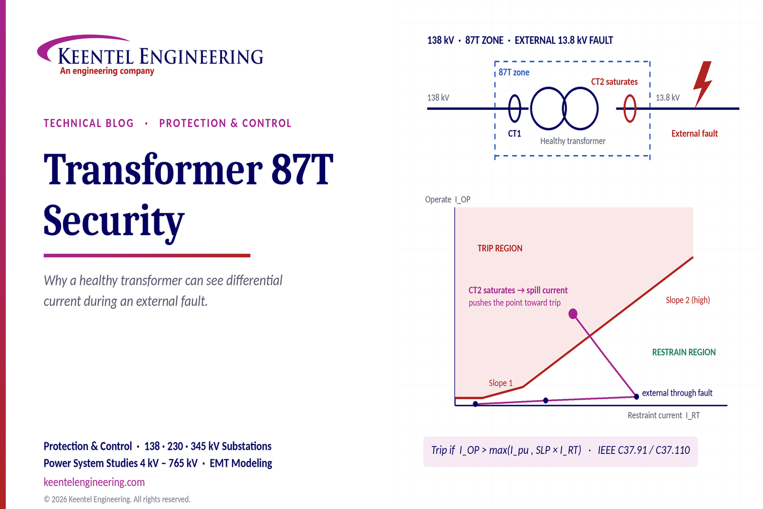
Learn why transformer differential relays detect current during external faults, how CT saturation causes spill current, and how secure 87T protection prevents trips.
By SANDIP R PATEL
•
October 10, 2026
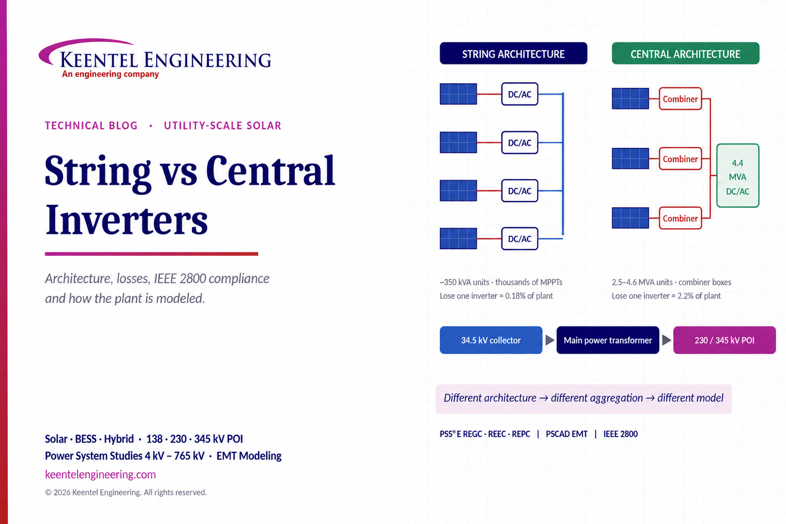
Compare string vs central inverters for utility-scale solar, including efficiency, maintenance, grid compliance, reactive power and interconnection studies.
By SANDIP R PATEL
•
October 9, 2026
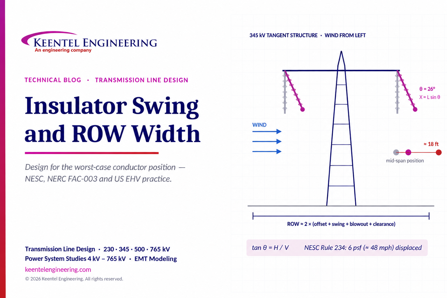
Learn how insulator swing angle and conductor blowout affect transmission line ROW width, with NESC clearances, NERC FAC-003 guidance, and a 345 kV example.
Copy

By SANDIP R PATEL
•
October 3, 2026
Engineering guide to PRC-028 disturbance recording, PRC-029 ride-through and PRC-030 event detection for inverter-based resources.

By SANDIP R PATEL
•
October 3, 2026
A practical guide to SSO classification, SSR, PEDI, Wind-SSCI, EMT analysis, mitigation and protection based on CIGRE TB 909.

By SANDIP R PATEL
•
October 3, 2026
Learn ERCOT generator testing for PFR, MOD-025 and MOD-026/027, including staged tests, capability verification, dynamic models and field testing.





